1. Introduction
Among the devices for transporting bulk materials, vibratory conveyors play a significant role. They are used for transport over short distances, not exceeding several dozen meters. The frequency of the vibratory conveyor trough can range from 10 to 100 Hz and can be sub-resonant, resonant, or super-resonant, depending on whether it is lower, equal to, or higher than the natural frequency of the conveyor. The amplitude of vibrations can range from a few tenths of a millimeter to a few millimeters.
Figure 1 shows a typical vibratory conveyor of classical construction [
1]. The trough (1), vibrator (2), and suspension (3) are rigidly connected and together form a transporting machine—a vibratory conveyor. The troughs of these conveyors perform cyclic periodic movements with variable speed and variable acceleration, which causes the interaction—through the trough support system (3)—of variable dynamic forces on the ground. The material in the trough, due to its movements, either undergoes temporary slips or makes jumps, thus moving in the direction of transport.
One of the main requirements for modern vibratory conveyors, apart from high reliability and low energy consumption, is the ability to control the conveyor’s capacity. Controlling the transport speed, and thus the capacity of the conveyors, is essential in cases where conveyors operate in production lines [
2,
3,
4,
5,
6]. A particularly sought-after case of capacity control is the complete stoppage of transport without stopping the drive. High dynamics of stopping and restarting are often required for this. Conveyors capable of such operation are called dosing conveyors or dosing feeders. An additional parameter that is crucial in the process of transporting materials is the energy efficiency of the devices.
In the literature, there are practically no studies concerning such resonant conveyors driven by rotational inertial excitation. There are studies on conveyors actuated by electromagnetic excitation [
7], which also utilizes the effect of dynamic excitation; however, the dynamic characteristics of these solutions differ significantly. In the literature, the term
resonant conveyor often appears in works concerning conveyors operating based on Frahm’s dynamic vibration eliminator principle, in which the trough acts as a vibration eliminator for the frame that is being excited [
8]. It seems that calling such conveyors
resonant is incorrect as they do not operate in the resonance but rather in the anti-resonance of the frame vibrations. Therefore, a more accurate term would be
base-excited conveyors [
9].
The literature, limitedly, also addresses the dosing of bulk materials using vibratory conveyors powered by rotary unbalanced masses. Most such conveyors employ electromagnetic excitation. Kinematic excitation can also be used, but, in this case, the analysis is relatively simple, which has probably led to a lack of interest from researchers in such solutions. On the other hand, the industry applies such systems to a very limited extent due to the low durability of the devices in which the drive uses friction elements (eccentrics), which are not effective in dusty environments. There are also new patented solutions that enable very precise dosing by employing Frahm’s dynamic eliminator to suppress the vibrations of the trough [
2,
4]. These solutions have not yet been introduced into industrial use, so, in this case, only analytical, simulation, and laboratory studies can be relied upon.
In the case of conventional conveyors, where the trough is directly driven (
Figure 1), material dosing is difficult because they operate in the super-resonant zone, where the amplitude changes very little with changes in the excitation frequency (e.g., when decreasing it). Of course, reducing the excitation frequency will lower the transport speed to some extent. However, further reduction in excitation frequency leads to entering the system’s resonant zones. There are solutions where the trough–suspension system is tuned in such a way that resonance occurs at very low frequencies, allowing transport to be stopped above the resonance point. However, this approach has significant drawbacks as the system becomes unstable due to the soft suspension, and it also requires the excitation frequency to be varied over a very wide range. Additionally, such a conveyor doses material by significantly changing the frequency rather than the amplitude, which causes the material to stop behaving like a fluid at low excitation frequencies. Thus, the dosing precision is limited.
2. Conveyor with Additional Resonant Mass
This study analyzes the transport performance of resonant conveyors with two degrees of freedom in the direction of the machine’s working vibrations. These types of conveyors have been established for over fifty years.
The principle of operation of this type of machine is as follows. An additional mass, suspended on its suspension to the transporting trough, is driven using a relatively small vibrator. The forcing power constitutes about 20% of the force that would be needed to drive a similar conveyor of classical construction from
Figure 1, and therefore the driving motor can be small in size with lower energy demand. The forcing frequency should be chosen so that the system operates on the slope of the second resonance, which occurs in the direction of the working vibrations. Thanks to working near the resonance, there is a significant excitation of the trough amplitude with a small forcing power, significantly reducing the energy demand of the device. In the direction perpendicular to the vibration direction, the system does not excite to significant vibrations because there is no resonant excitation, and the drive is small. There are also solutions of this type of conveyor in which the drive consists of two counter-rotating electrovibrators, as in the example in
Figure 2.
In such a solution, the resultant force acts in the direction of the vibrations, passing through the center of gravity of both masses, and there is no risk of vibrations in the perpendicular direction or angular vibrations in the entire machine. These types of conveyors were forgotten for many years due to the difficulty in accurately controlling the forcing frequency. A slight change in it significantly changes the vibration amplitude and thus the transport speed. An additional threat is the possibility of the system entering resonance and thus destroying the machine. Today, the proliferation of cheap frequency inverters and control systems that allow precise control of the forcing speed and vibration amplitude has enabled the widespread use of these types of devices. These control systems are typically based on closed-loop feedback control, in which the amplitude of vibrations is the controlled variable and the forcing frequency is the manipulated variable. Currently, many companies involved in vibrating transport offer such machines.
Additionally, the significant increase in energy costs has influenced the spread of these types of machines. Due to the use of a small electrovibrator compared to classical conveyors, their production cost is lower while the efficiency of these types of machines is significantly higher. Despite the significant increase in interest in these types of machines, there are practically no scientific studies on classical resonant conveyors. It should be noted that they differ in construction from conveyors operating in the anti-resonance basin, where the trough acts as a forced mass eliminator. Due to this, vibration transmission to the ground can be reduced. These types of conveyors, often incorrectly called resonant, should rather be called anti-resonant [
9,
10,
11]. They also differ from conveyors or two-mass kinematically forced separators [
12,
13]. Conveyors driven by expensive and energy-intensive electromagnetic excitation [
14,
15,
16] have a construction similar to the conveyors analyzed in this paper due to the additional mass inside the drive, but, due to the different drive, the conclusions contained in the papers describing them cannot be applied to the conveyors analyzed in this paper.
Resonant conveyors transmit dynamic forces to the ground slightly greater than classical conveyors of the same parameters due to their larger mass. The greater mass, due to the stability of the system requires a stiffer main suspension, and, since the trough amplitude at the operating point for resonant and classical conveyors is the same, the forces transmitted to the ground will be greater.
3. Mathematical Model
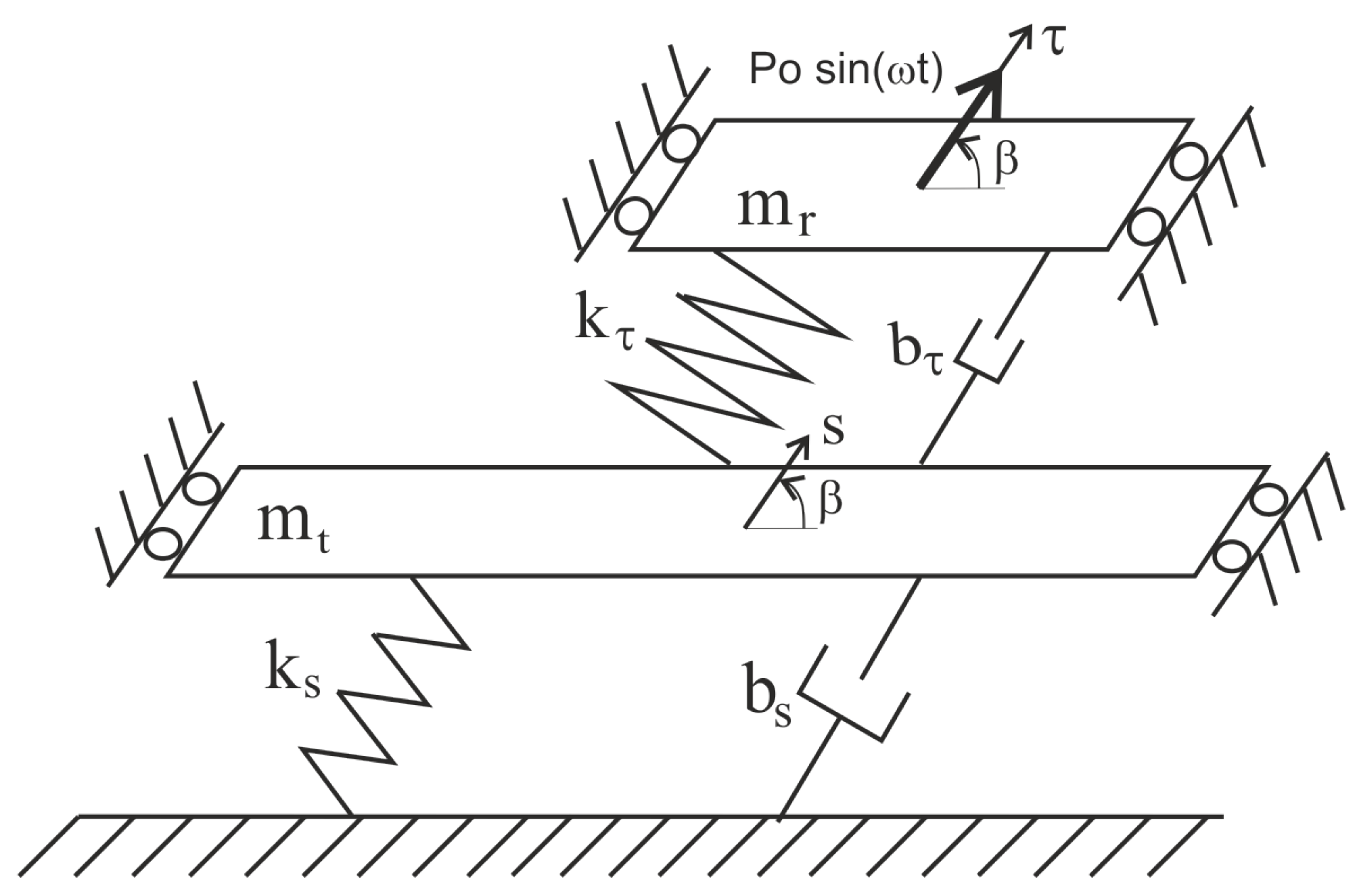
The analyzed conveyor can be considered as two systems in two perpendicular directions: in the direction of trough vibrations and in the perpendicular direction. In the direction perpendicular to the trough vibrations, the vibrations are small because they will not be excited due to the small drive and lack of dynamic excitation. In the case of the conveyor shown in
Figure 2, there will be no vibrations in the direction perpendicular to the working vibrations (except during startup and rundown) because the force from the two counter-rotating electrovibrators is directional. In the direction of the working vibrations of the trough, due to the dynamic excitation by the additional mass, the vibrations, despite the small energy-efficient drive, will reach significant values. The dynamic model in this direction is shown in
Figure 3.
In the design of vibratory conveyors, it is standard practice to ensure that the suspension stiffness in the x- and y-axes is either identical or closely matched. This approach minimizes the number of resonance zones encountered during start-up and shut-down phases of operation. From a dynamic perspective, such symmetry in stiffness mitigates the risk of the system becoming entrapped at a resonant frequency during acceleration, which could lead to severe operational instability or drive failure. Accordingly, in the present study, we assume that . Even in cases where this condition is not strictly met, the impact on the subsequent analytical considerations is negligible. This is because the suspension stiffness in question pertains to the system’s primary mode of vibration (i.e., the first resonance), which exerts minimal influence on the higher-frequency resonance near the system’s steady-state operating point.
The systems have four degrees of freedom associated with the coordinates
x,
y,
, and
. Assuming that
and the direction of the forcing force passes through both the center of gravity and the center of the suspension system, the conveyor systems can be reduced to the system shown in
Figure 4.
Simplifying the model allows for the analytical determination of amplitude–frequency dependencies, and thus the dependence of transport speed on the forcing frequency. The equations of motion of the model are as follows:
Assuming monoharmonic force of the form
where
and limiting this investigation to the steady state, the system of differential equations can be reduced to the following forms:
where
T—amplitude of the harmonic motion along the coordinate;
S—amplitude of the harmonic motion along the s coordinate;
—angular frequency of the excitation force ;
i—imaginary unit;
—mass of the resonator;
—mass of the trough;
m—sum of unbalanced masses of the vibrator;
e—eccentricity of mass m;
k, b—total elasticity and damping of the spring strips in the working direction;
—elasticity coefficient of the support system of the vibration isolating frame;
—damping coefficient of the support system of the vibration isolating frame.
After solving these equations against
T and
S, we obtain the complex value of the amplitudes:
The complex modulus of the amplitude values determine the real value of the amplitudes:
The damping of suspension systems is described by the following relationship:
In the case of elastic suspensions, system damping arises from a combination of phenomena that are difficult to isolate and quantify individually. Primarily, it is associated with internal material damping within the suspension’s structural elements. For steel suspensions in particular, damping is largely influenced by the method of mounting, which contributes to energy losses due to friction. The overall damping magnitude is strongly dependent on the suspension stiffness and the excitation frequency—parameters that are of central importance in the analyses presented in this study. In mechanical systems, damping can be estimated using Equation (
7), which incorporates an experimentally determined dimensionless coefficient, denoted as
, reflecting the combined effects of material properties and mounting configurations. For suspensions employing helical compression springs mounted on pivots, the value of
has been determined to be approximately 0.13 [
17].
These equations make it possible to analyze the movement capabilities of the conveyor system depending on the frequency of the exciting force.
4. Analytical Studies
The analytical study was based on the typical parameters of a small vibratory conveyor. A representative trough was assumed, with a length of approximately 2 m, a cross-section of approximately 500 × 200 mm, and a mass of 65 kg—sufficient to ensure a throughput capacity of up to 30 tonnes per hour. The mass of the resonator is treated as a variable. The stiffness of the suspension between the trough and the resonator masses was determined using the engineering formula derived below—Equation (
11). The stiffness of the primary suspension is defined as a function of the variable resonator mass, such that a constant static deflection is maintained in accordance with Equation (
10). All the parameters are summarized in
Table 1.
It should be remembered that the stiffness of the suspension between the masses must be variable for a variable resonator mass so that the second resonant frequency of the system’s vibrations remains constant for a given conveyor, e.g., 157 rad/s (which is the synchronous frequency of a two-pole asynchronous motor). The frequency at the operating point will be slightly lower due to the desired amplitude of the working vibrations. For the parameters in
Table 1, this frequency is approximately 152 rad/s. The difference between the resonant and nominal frequencies thus constitutes a reserve for controlling the amplitude of the lift.
Starting from Equation (
1), neglecting the damping and the forcing force (i.e., for a free system), the higher of the two resonant frequencies is given by the formula
The above quadratic equation has one solution due to the suspension stiffness
:
Taking into account the deflection of the entire machine, which should not depend on the resonator mass and should remain constant due to its stability, we obtain the dependence on the stiffness of the main suspension:
where
is the assumed static deflection of the entire machine.
By substituting the above into Formula (9), we obtain
Using this formula, knowing the frequency for which the conveyor is designed, the stiffness of the suspension between the additional mass and the conveyor trough can be determined. From an engineering perspective, when designing this type of conveyor, after determining the suspension stiffness and selecting it from the catalog, the exact resonator mass (which can be easily changed within a small range) should then be selected from the dependency:
which is the positive solution of the quadratic Equation (
11) due to the value of the resonator mass.
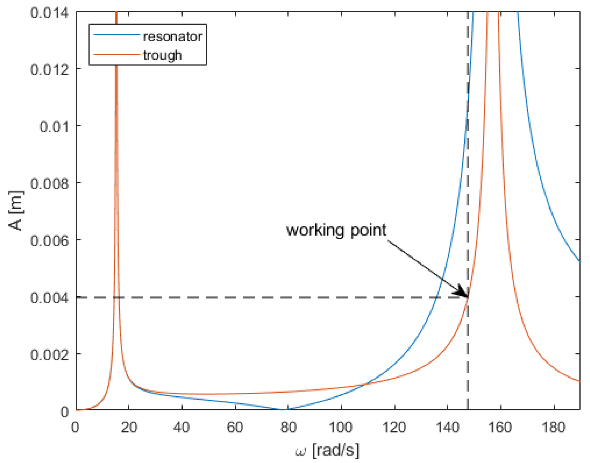
Figure 5 shows the amplitude–frequency dependence of the trough in the working direction and the additional resonator mass to which the electrovibrator is mounted. The figure shows two resonances, while the operating point of the machine is at the second resonance, around 150 rad/s.
To determine the transport speed, the following dependency was used [
18]:
where
is the lift coefficient and
= 0.9 is the coefficient that corrects the influence of differences in the properties of the actual material layer on the trough and the properties of the assumed feed model. This coefficient also depends on the angle of inclination of the trough
, which in this case is in a horizontal position, and the angle of inclination of the resonant mass
. The constant in the denominator of Equation (
13) was determined experimentally [
18].
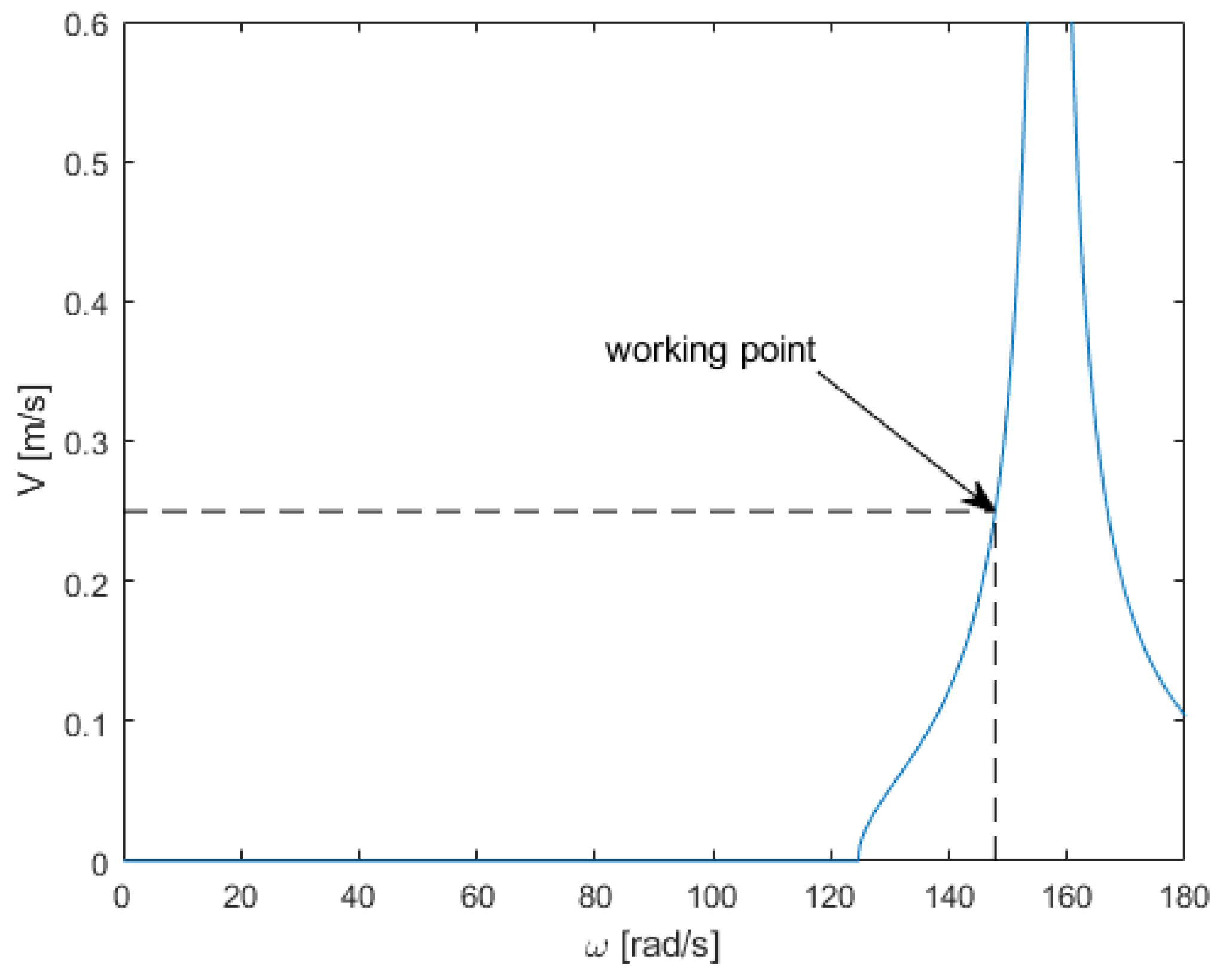
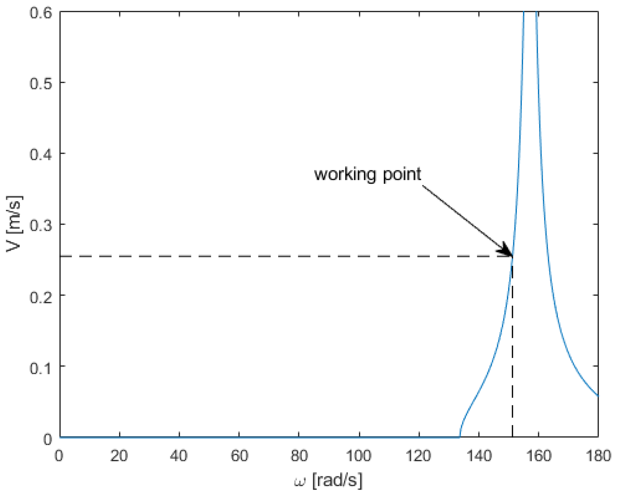
Using these dependencies, the transport speed was determined based on the forcing frequency. It can be seen that, for this type of conveyor, transport does not occur around the first resonance. In the case of the analyzed conveyor, the transport begins at a forcing frequency greater than 125 rad/s and reaches a nominal value of 152 rad/s.
The conveyor, using a smaller drive with a force power that constitutes 20% of the power needed to drive a classical conveyor, has very good transport properties, and speed is easily regulated by changing the force frequency (
Figure 6). It is also suitable for material dosing in the full range. The problem with this type of conveyor is that, with its typical parameters, where the resonant mass is significantly lighter than the trough mass, we obtain significantly higher amplitudes of resonator vibrations than the trough at the operating point (
Figure 5), which results in reduced structural strength. On one hand, the accelerations the drive is subjected to are greater than the accelerations it would experience if mounted on the trough, causing significant loads on its bearings. However, it requires a stronger suspension between the masses to withstand the high amplitudes. The solution to this problem may be a significant increase in the resonant mass up to a mass comparable to the trough.
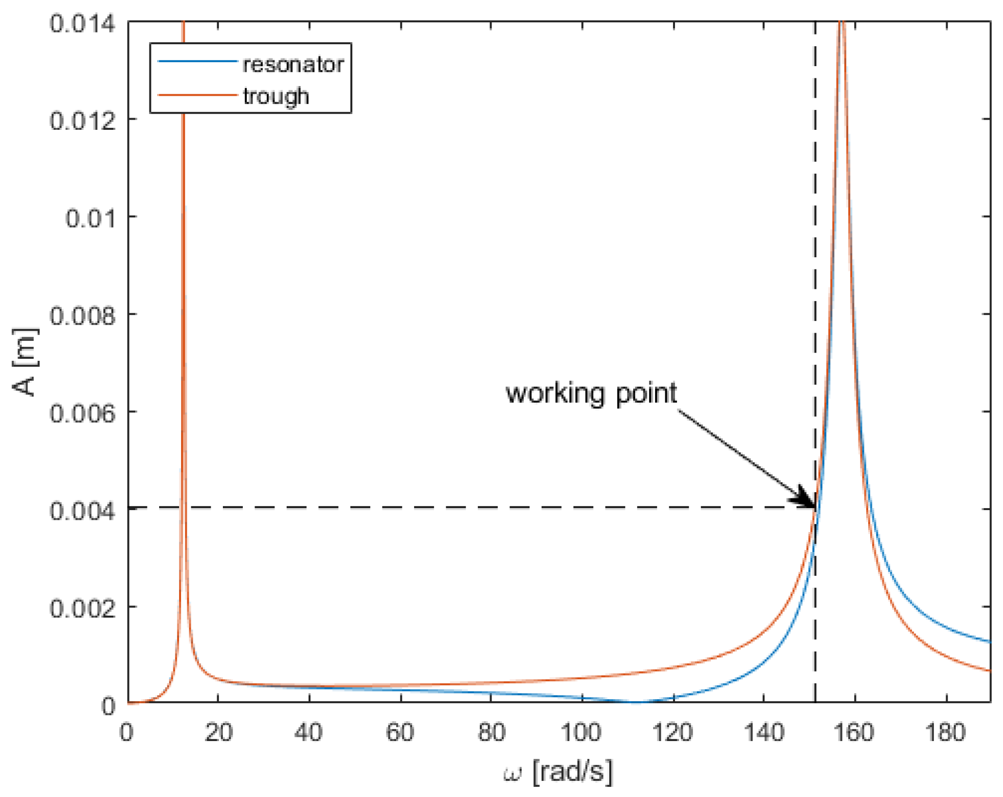
Figure 7 shows the amplitude–frequency dependence of the trough in the working direction and the additional resonator mass increased to the trough mass. In such a solution, the amplitude of the resonant mass vibrations is similar to the amplitude of the trough vibrations.
Figure 8 shows the transport speed for similar troughs and resonant masses. Keeping the operating point at 152 rad/s, transport can be stopped by reducing the forcing frequency to 135 rad/s. This is particularly important for quick and precise dosing due to the greater sensitivity of the conveyor. It also affects energy efficiency during dosing as less energy is needed to reduce the electrovibrator’s speed and then accelerate it again because of the smaller speed differences required to stop and resume transport. Quantitatively speaking, in the case of a larger resonator mass, stopping the transport requires a reduction in the excitation frequency by 17 rad/s, whereas, for a smaller resonator mass, the required reduction is 27 rad/s. Therefore, the larger mass requires a 62% smaller frequency adjustment to stop the transport.
An important issue is the impact of increasing the mass of the resonator (while maintaining the drive size) on the maximum transport speeds. The graphs in
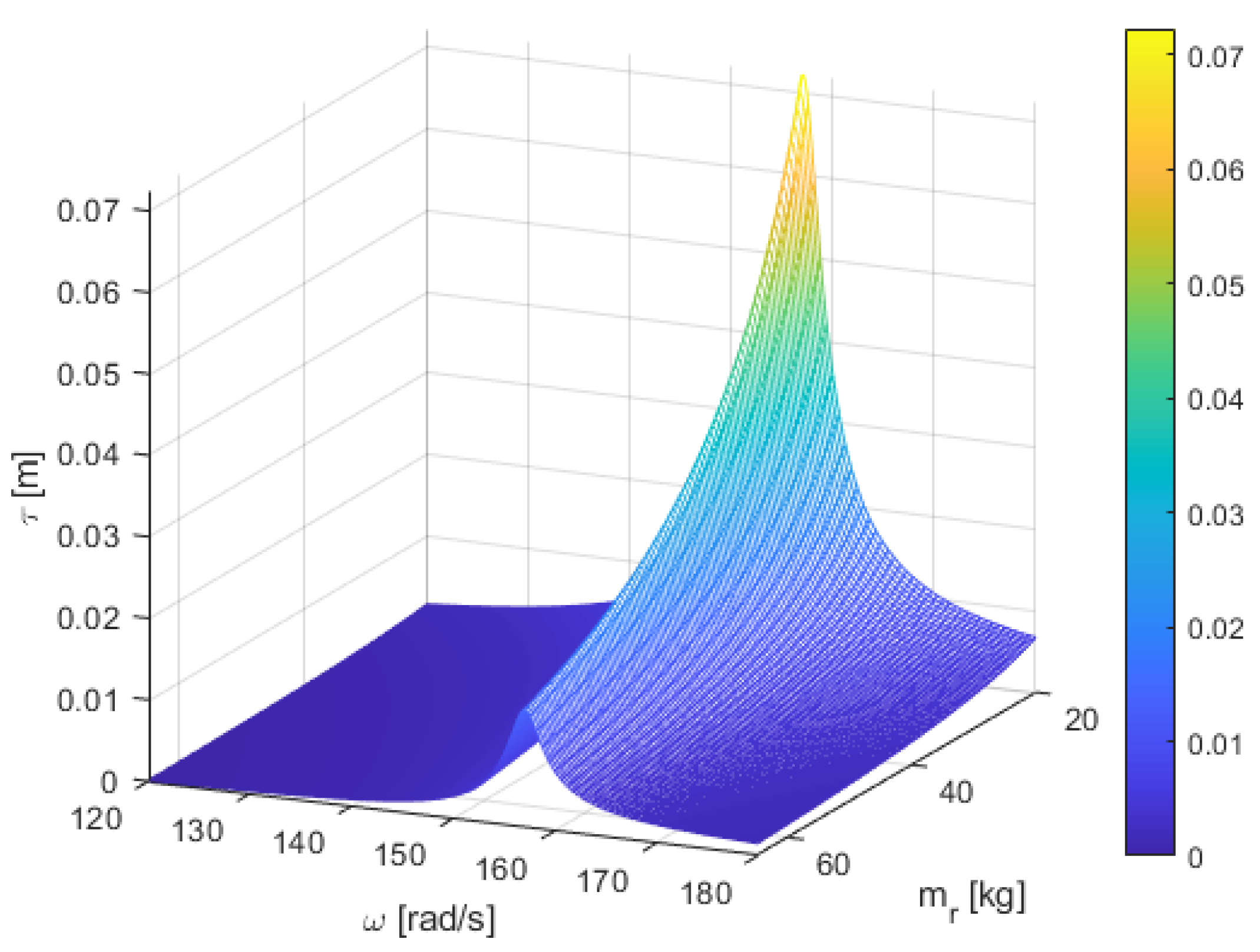
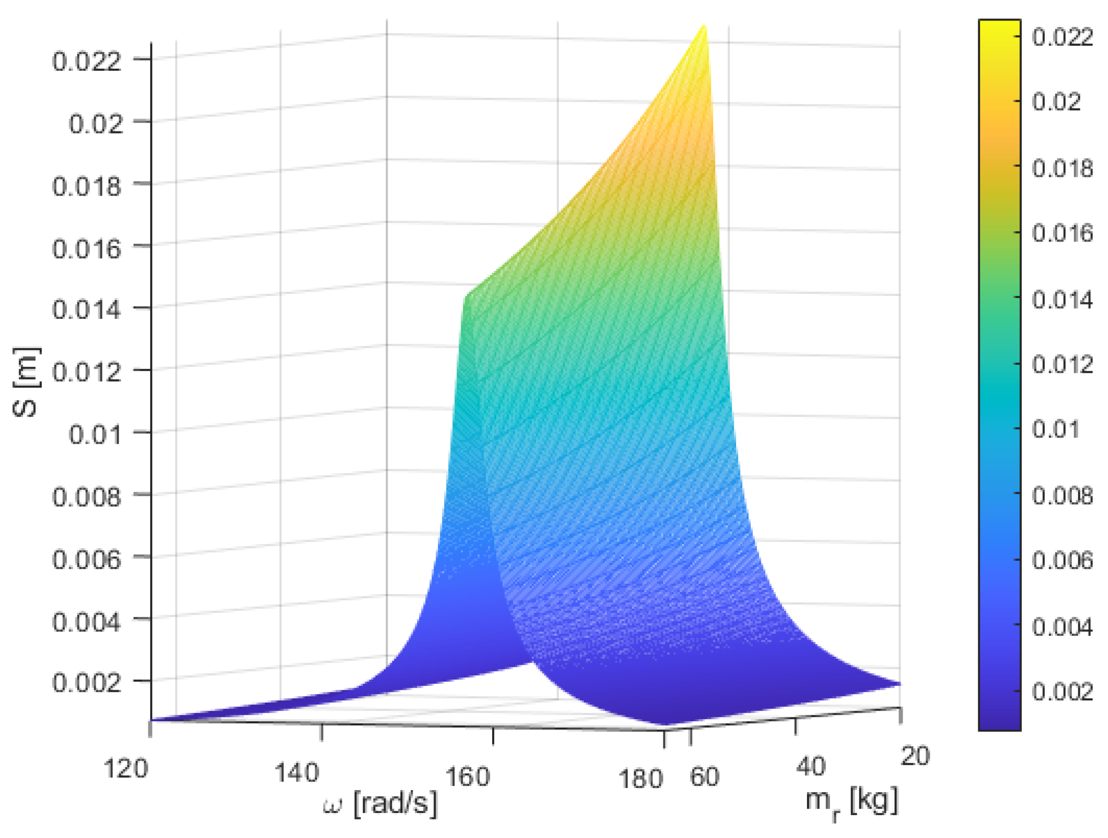
Figure 9 and
Figure 10 show the dependence of the amplitudes of the resonator mass and the trough on the resonator mass and the forcing frequency.
It can be observed that increasing the mass of the resonator has a minor impact on the amplitude of the conveyor trough vibrations; for more than a threefold increase in mass, the maximum amplitude decreases by approximately 35%, which affects the transport speed. It is also beneficial that increasing the resonator mass by more than threefold reduces its amplitude threefold, significantly extending the lifetime of the suspension between the masses as well as the drive attached to it.
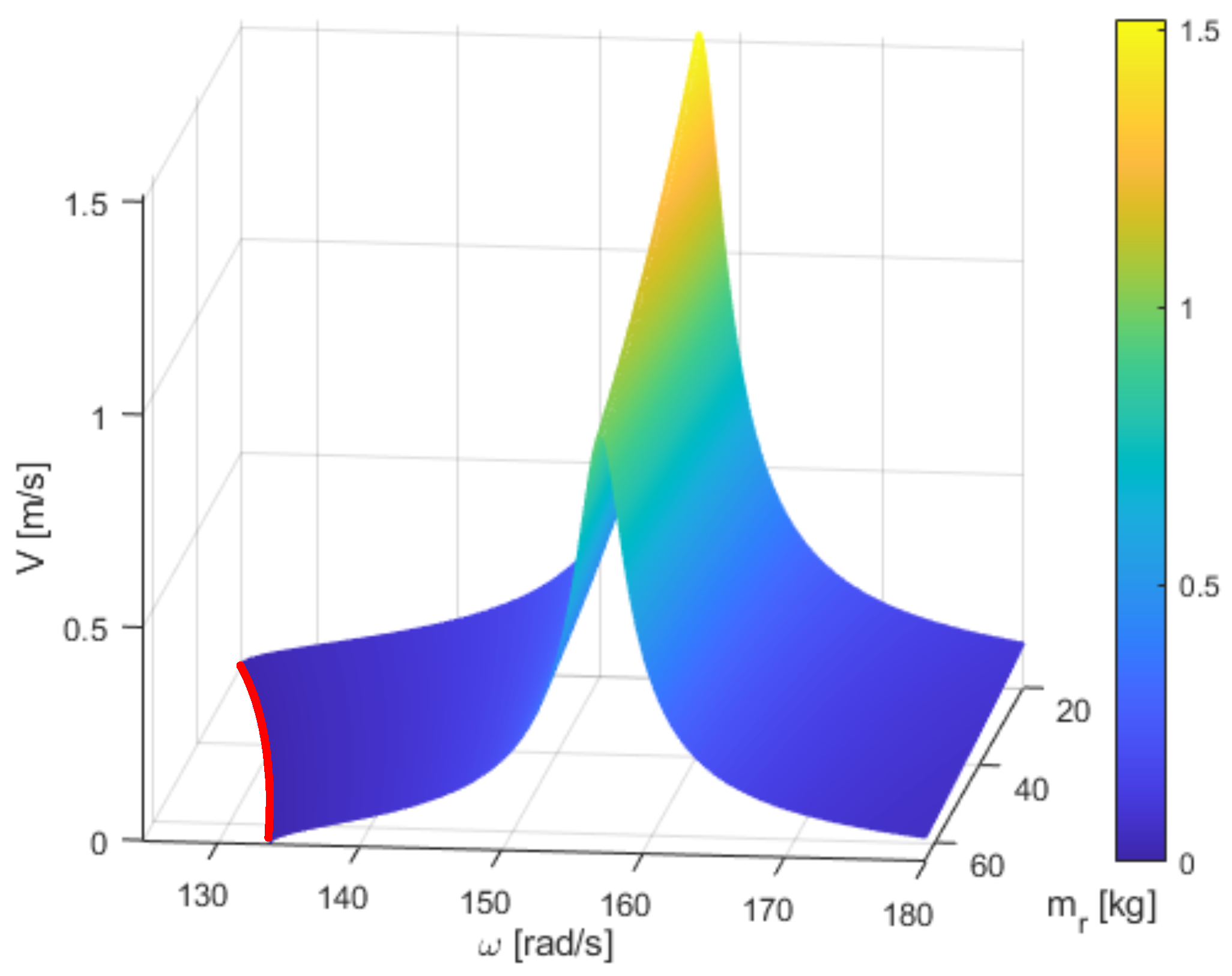
Figure 11 shows the dependence of the transport speed on the mass of the resonator and the excitation frequency. The red line marks the point where the transport stops. With an increase in the resonator mass, transport stops at higher forcing frequencies, increasing the machine’s potential for dosing. The graph confirms that the width of the transport zone narrows with increasing resonator mass.
As the resonator mass increases, in order to maintain the stability of the system, the stiffness of the main suspension must also be increased according to Equation (
10). Consequently, with the same amplitude of trough vibrations, greater forces will be transmitted to the ground according to the dependency
Which, taking into account dependencies (
7) and (
10), yields
where
A is the amplitude of the trough vibrations.
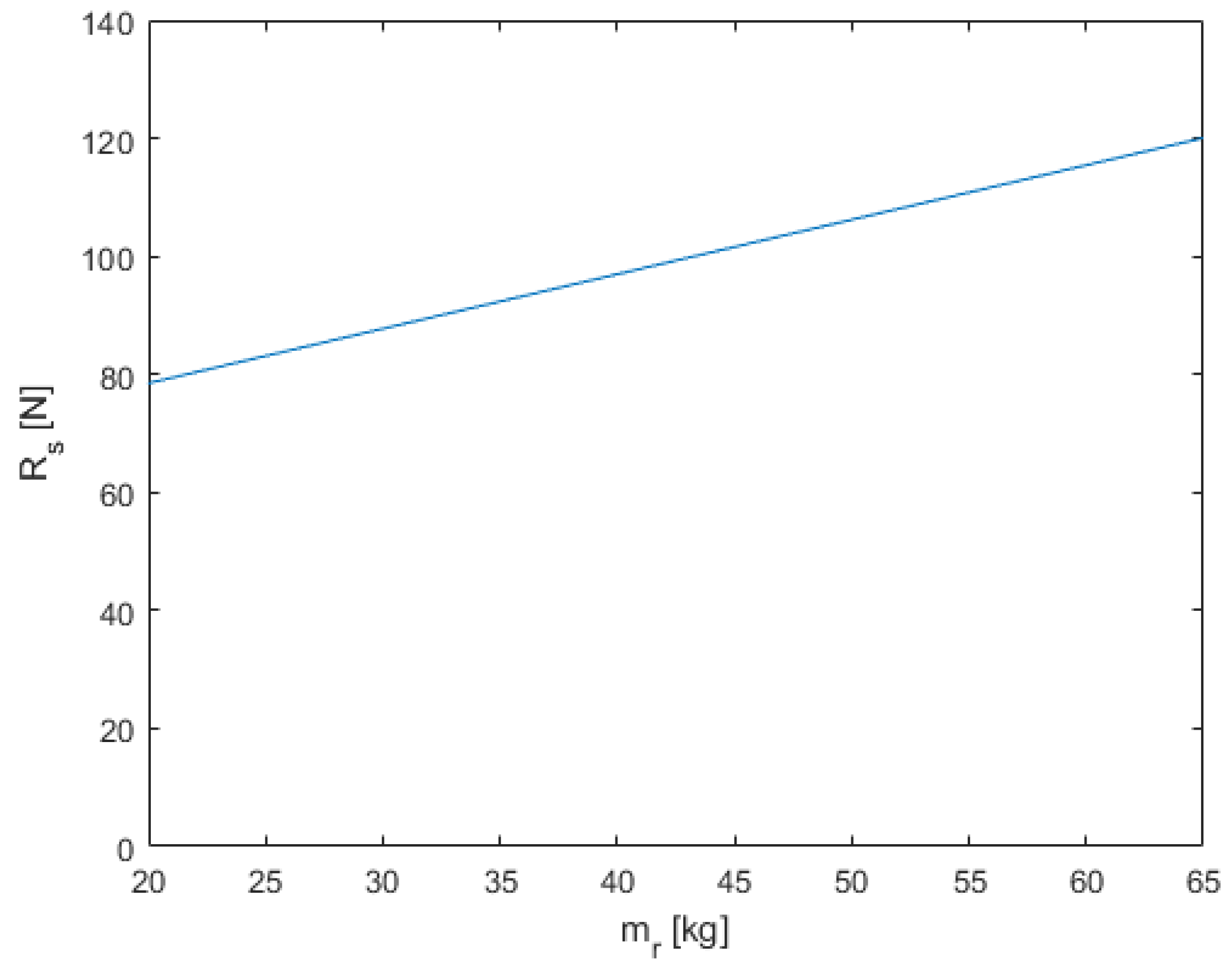
In the case of steady-state operation for a considered conveyor, A = 0.004 [m]. As seen in the graph in
Figure 12, which shows the dependence of the force transmitted to the ground at the operating point as a function of the variable resonator mass, with more than a threefold change in this mass, the force changes by about 25%.
An increase in the forces applied to the ground within a small range does not affect the machine foundation in terms of structural strength. However, it has a slight impact on environmental vibrations, particularly when the foundation used has a relatively low mass.
5. Conclusions
In summary, in conveyors using an additional mass to achieve a resonant system, it is possible to obtain the transport properties of classical conveyors, where the drive is mounted directly to the trough, with a significantly smaller and more energy-efficient drive. An additional advantage of this solution is the possibility of full-range dosing, which is very difficult to achieve with classical conveyors. Although these machines are often offered by companies that specialize in the production of transport equipment, there is little scientific research available that allows for a better design. In particular, such a design would enable their use for material dosing.
The conclusions drawn from this analysis can be summarized as follows:
The analyzed conveyors have very good transport properties across the entire range from stoppage to nominal speed when using a small energy-efficient drive, which constitutes 20% of the drive size used in typical constructions with the same parameters.
A feature of the design is the necessity of using an inverter that allows precise control of the vibrator’s rotational speed.
The drawback is the presence of significant vibrations of the additional mass acting as a resonator to which the drive is attached.
However, with the use of an increased resonator mass, comparable to the mass of the trough, its amplitude is similar to the amplitude of the trough, protecting the drive and the suspension between the masses.
Increasing the resonator mass also has a very positive effect when the conveyor is used for material dosing by increasing the sensitivity of the transport speed to changes in the forcing frequency by 28%.
To date, there are virtually no academic studies concerning this class of resonant conveyor, which is surprising given its growing industrial adoption. Manufacturers of such machines often rely on empirical trial-and-error methods in the absence of a robust mathematical framework capable of guiding design optimization. In the present study, in addition to highlighting the benefits of incorporating a relatively massive resonator, the authors have derived and proposed engineering-oriented formulas (Equations (
11) and (
12)) that significantly facilitate the design and optimization of key machine parameters. Future research should involve the development and analysis of a complete mathematical model of the conveyor system, including the influence of the transported material (the payload). This would enable investigation into the effect of payload mass on conveying velocity—a factor that may be critical in systems operating near resonance. In such cases, a portion of the payload may dynamically interact with the trough mass, effectively altering the system’s resonant frequency. The authors are actively working on the development of such a model. As a further research step, the authors intend to design and construct a laboratory-scale prototype with industrially relevant parameters. This setup will incorporate a drive control system capable of maintaining a constant vibration amplitude, irrespective of variations in suspension characteristics and payload mass over time during operational conditions.


