Strontium-Doped Tin Oxide Nanofibers for Enhanced Visible Light Photocatalysis


Abstract
1. Introduction
2. Experimental Methods
2.1. Materials and Reagents
2.2. Fabrication of Strontium-Doped SnO2 Nanofibers
2.3. Material Characterization
2.4. Electrochemical Measurements
2.5. Photocatalytic Experiment
3. Results and Analysis
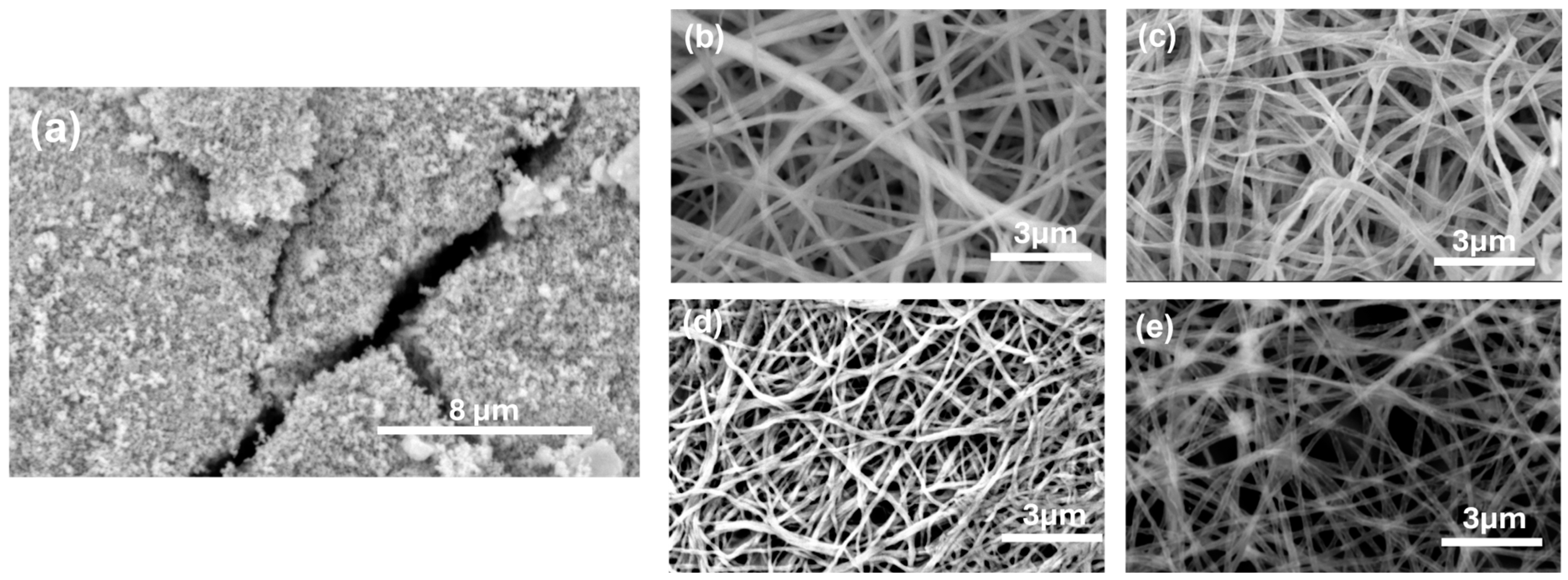
3.1. Morphological Evaluation of SnO2 NFs
3.2. Structural Properties
3.3. Electrochemical Studies
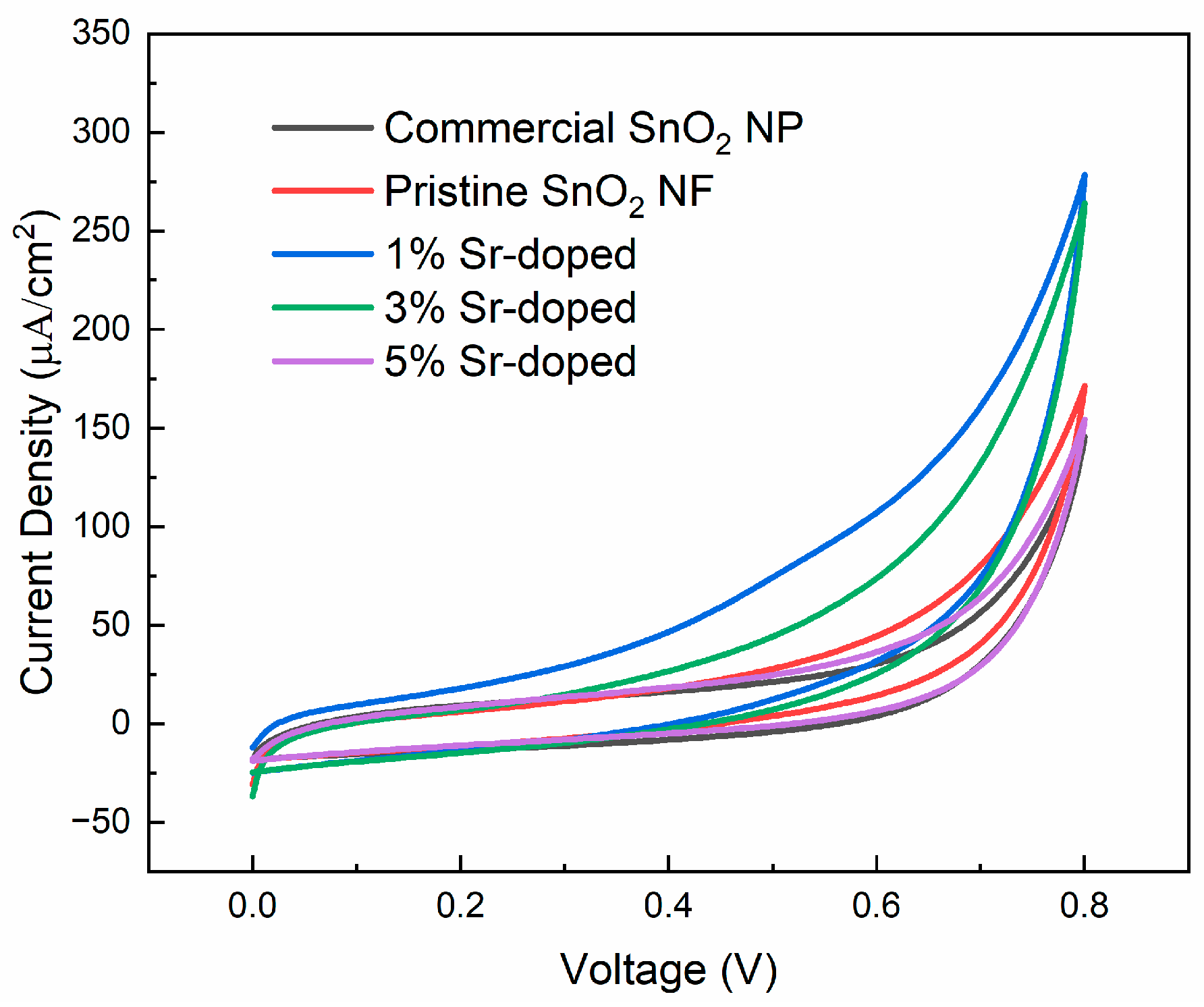
3.3.1. Cyclic Voltammetry (CV)
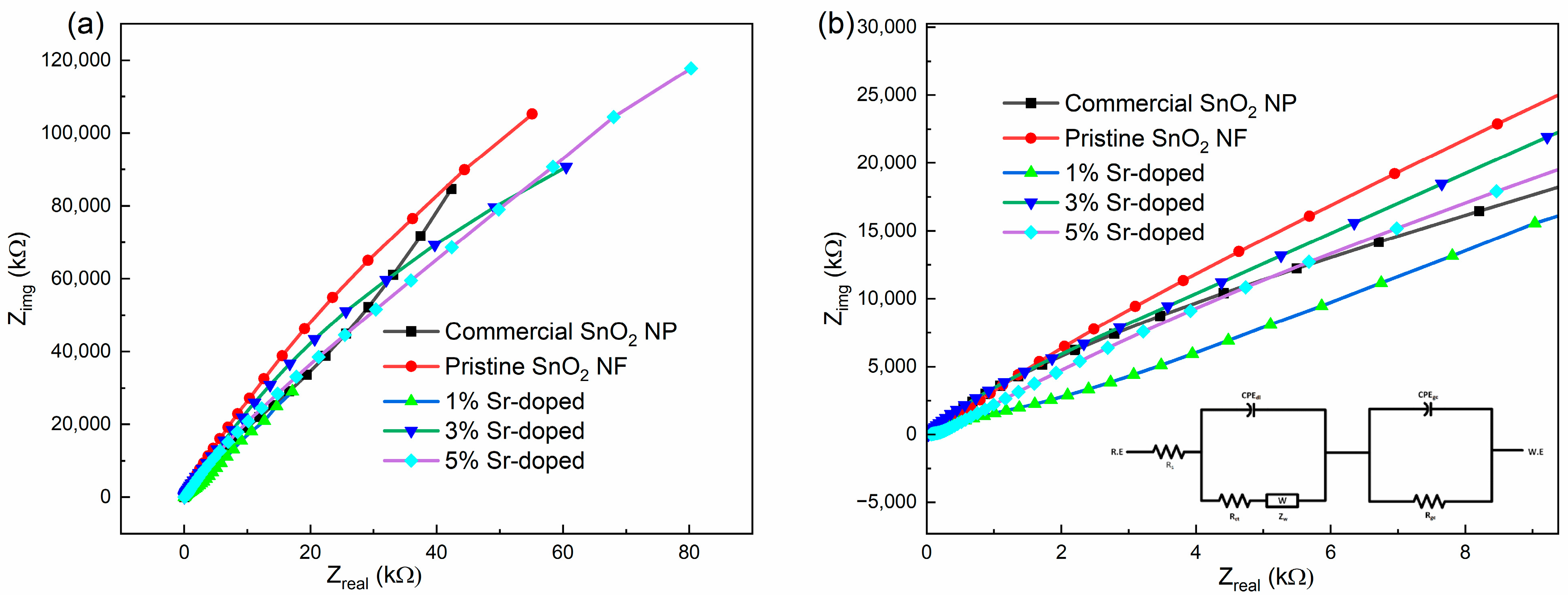
3.3.2. Electrochemical Impedance Spectroscopy (EIS)
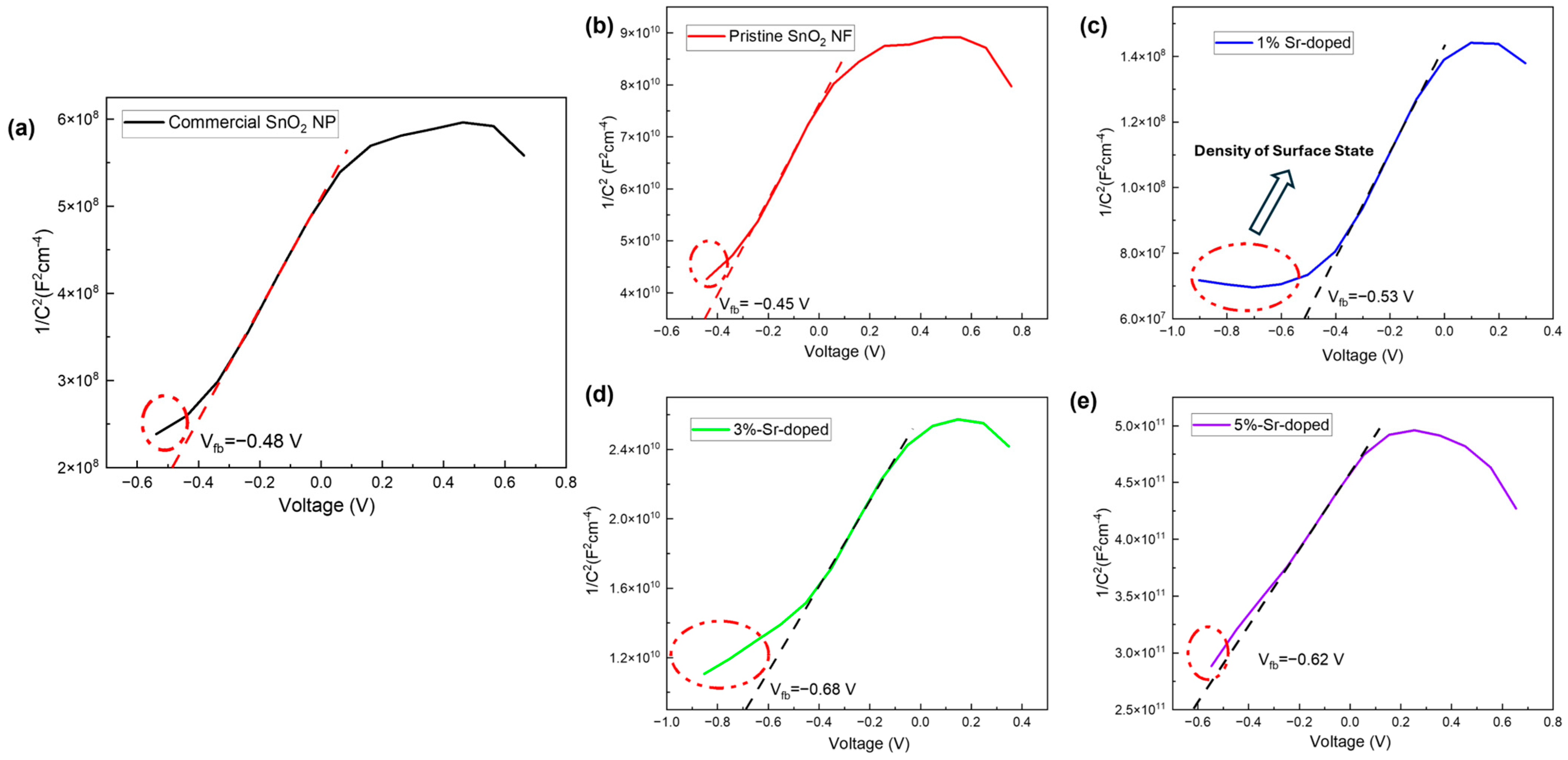
3.3.3. Mott–Schottky (MS) Plot
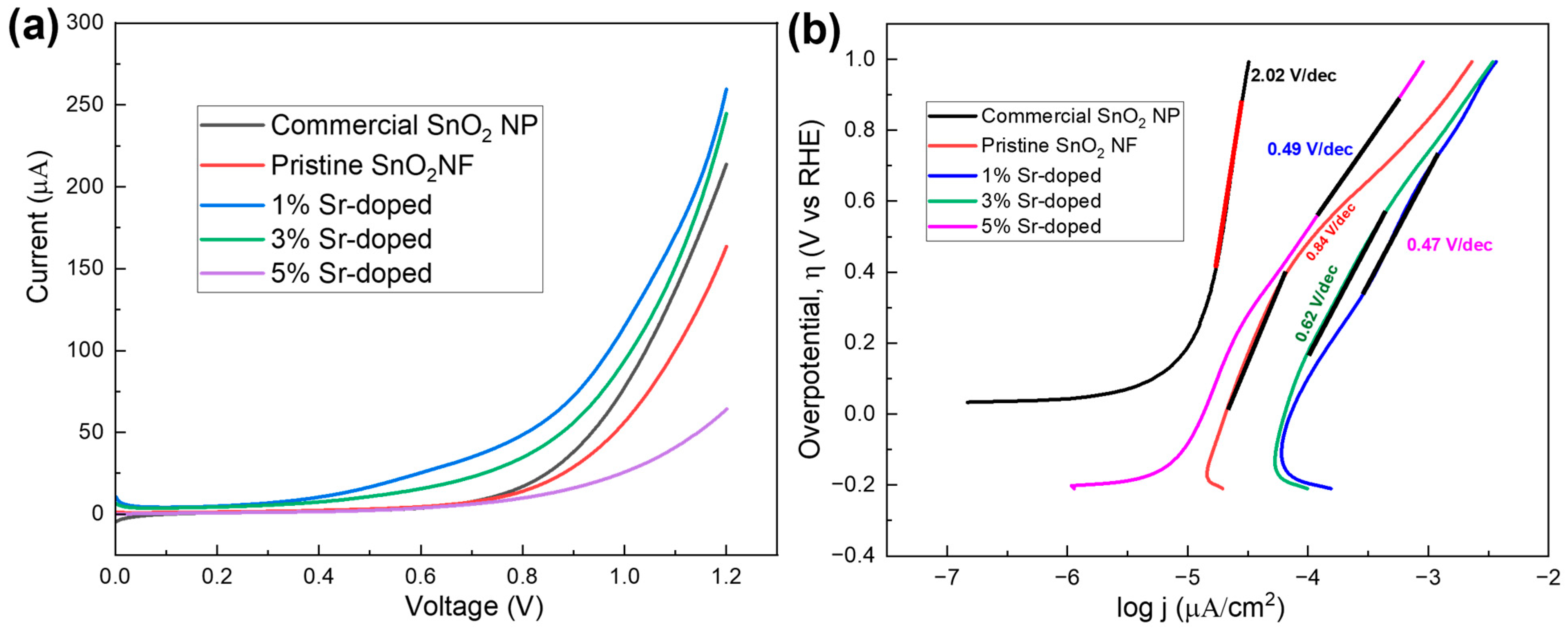
3.3.4. Linear Sweep Voltammetry (LSV)
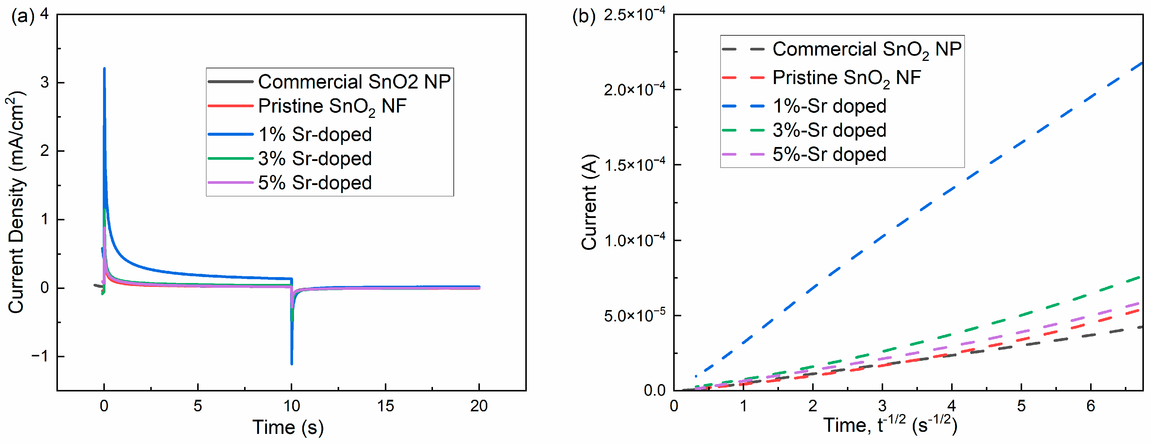
3.3.5. Chronoamperometry (CA)
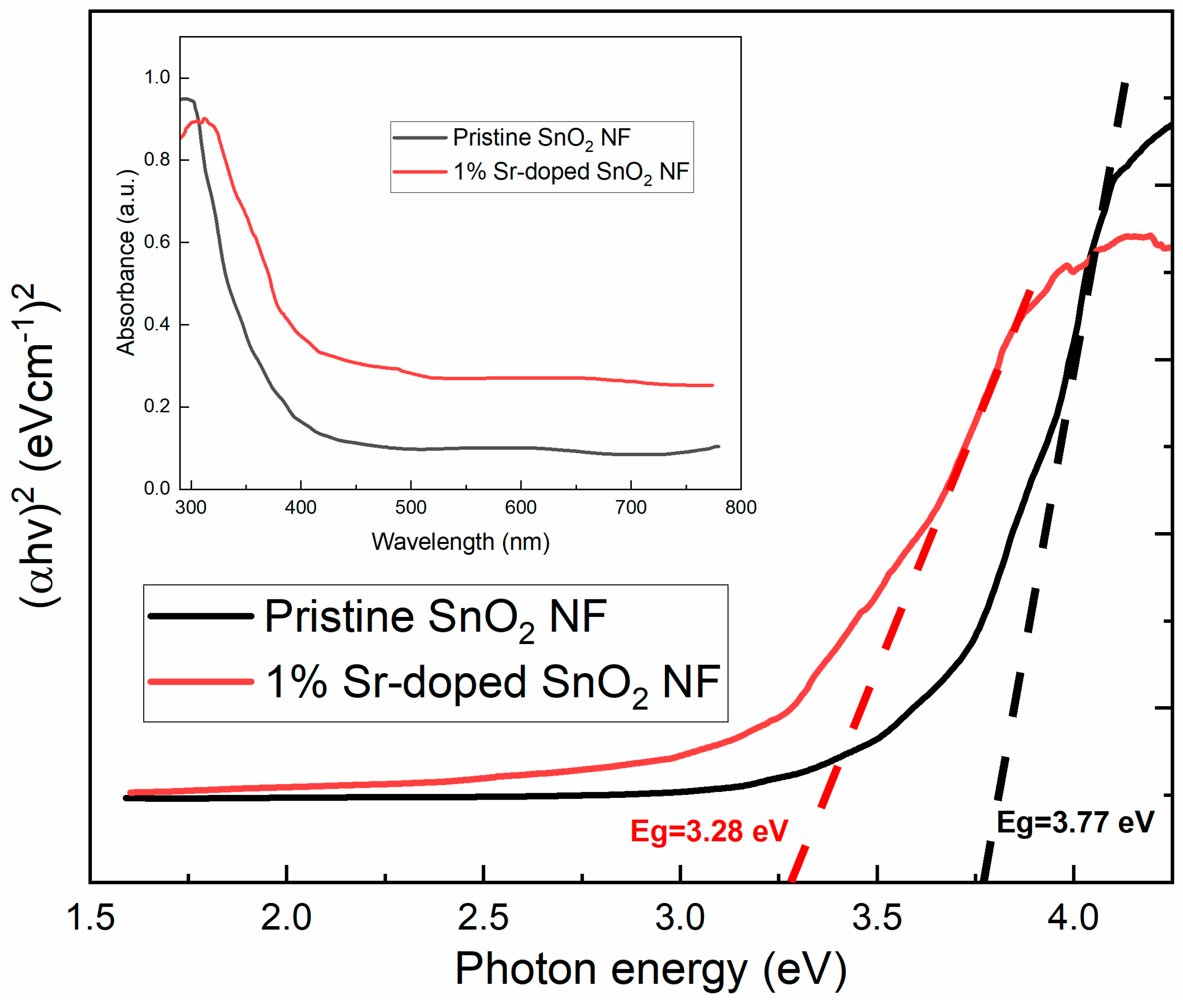
3.4. Optical Properties
3.5. Photocatalytic Degradation
3.5.1. UV Light as a Light Source
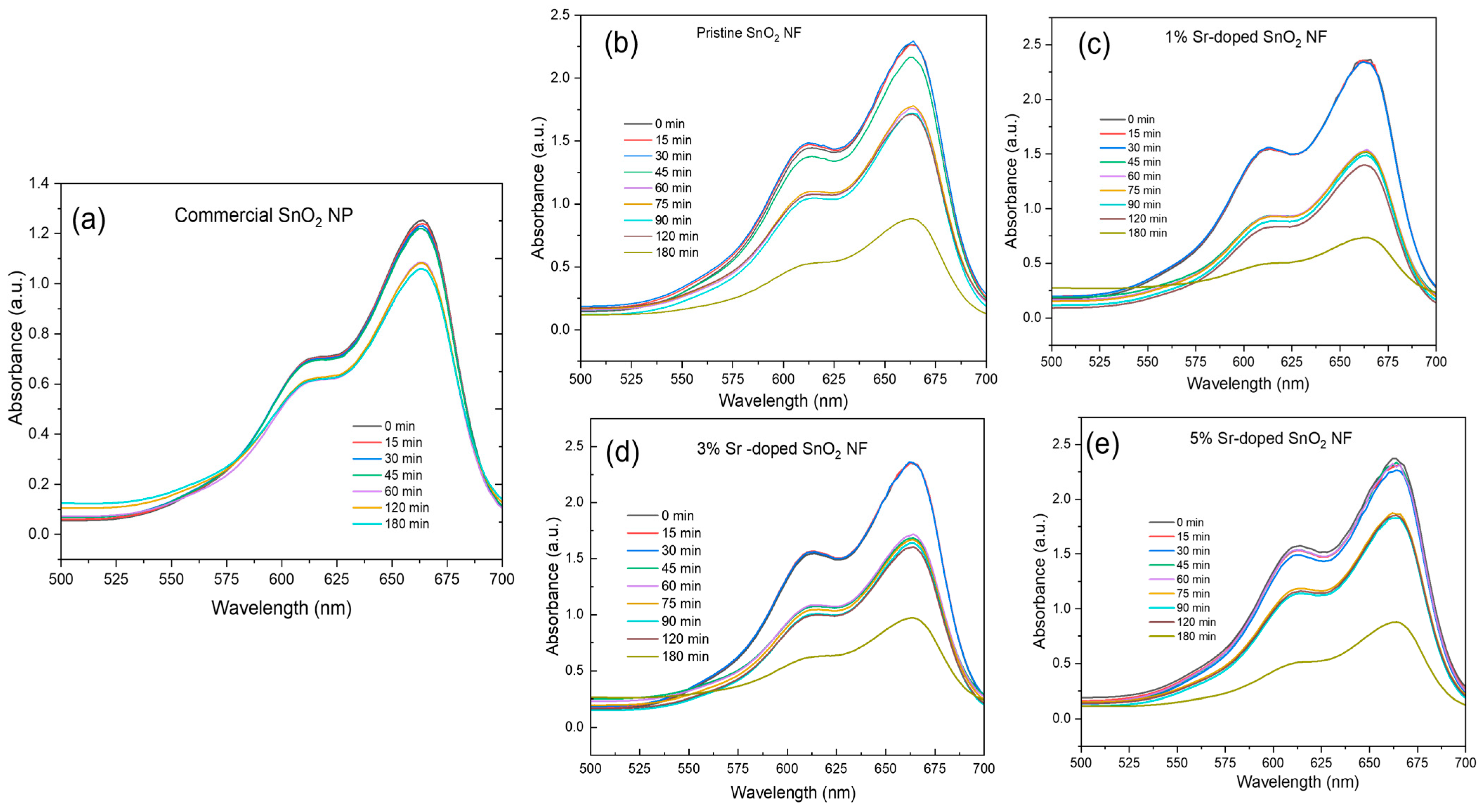
3.5.2. Visible Light as a Light Source
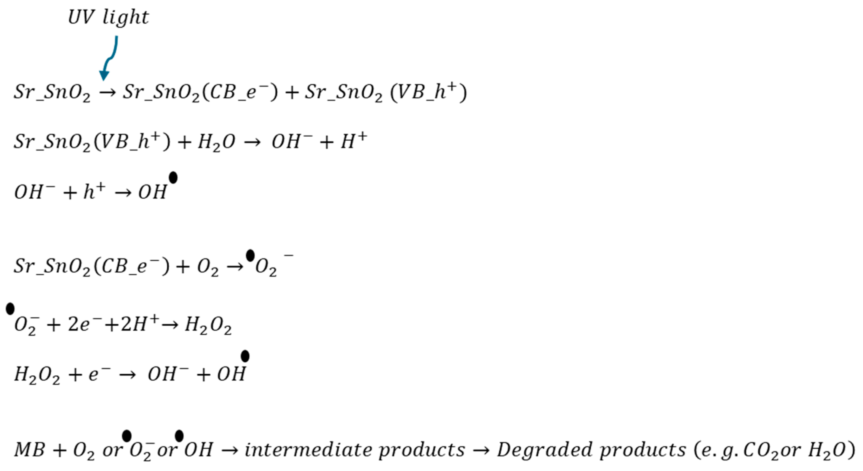
3.5.3. Photocatalytic Mechanism
4. Conclusions
Supplementary Materials
Author Contributions
Funding
Data Availability Statement
Acknowledgments
Conflicts of Interest
References
- Khan, S.; Noor, T.; Iqbal, N.; Yaqoob, L. Photocatalytic Dye Degradation from Textile Wastewater: A Review. ACS Omega 2024, 9, 21751–21767. [Google Scholar] [CrossRef]
- Pathak, D.; Sharma, A.; Sharma, D.P.; Kumar, V. A review on electrospun nanofibers for photocatalysis: Upcoming technology for energy and environmental remediation applications. Appl. Surf. Sci. Adv. 2023, 18, 100471. [Google Scholar] [CrossRef]
- Pantò, F.; Dahrouch, Z.; Saha, A.; Patanè, S.; Santangelo, S.; Triolo, C. Photocatalytic degradation of methylene blue dye by porous zinc oxide nanofibers prepared via electrospinning: When defects become merits. Appl. Surf. Sci. 2021, 557, 149830. [Google Scholar] [CrossRef]
- Dhanalakshmi, M.; Saravanakumar, K.; Lakshmi Prabavathi, S.; Abinaya, M.; Muthuraj, V. Fabrication of novel surface plasmon resonance induced visible light driven iridium decorated SnO2 nanorods for degradation of organic contaminants. J. Alloys Compd. 2018, 763, 512–524. [Google Scholar] [CrossRef]
- Shabna, S.; Dhas, S.S.J.; Biju, C.S. Potential progress in SnO2 nanostructures for enhancing photocatalytic degradation of organic pollutants. Catal. Commun. 2023, 177, 106642. [Google Scholar] [CrossRef]
- Sun, C.; Yang, J.; Xu, M.; Cui, Y.; Ren, W.; Zhang, J.; Zhao, H.; Liang, B. Recent intensification strategies of SnO2-based photocatalysts: A review. Chem. Eng. J. 2022, 427, 131564. [Google Scholar] [CrossRef]
- Ahmed, A.; Naseem Siddique, M.; Alam, U.; Ali, T.; Tripathi, P. Improved photocatalytic activity of Sr doped SnO2 nanoparticles: A role of oxygen vacancy. Appl. Surf. Sci. 2019, 463, 976–985. [Google Scholar] [CrossRef]
- Uddin, M.T.; Hoque, M.E.; Chandra Bhoumick, M. Facile one-pot synthesis of heterostructure SnO2/ZnO photocatalyst for enhanced photocatalytic degradation of organic dye. RSC Adv. 2020, 10, 23554–23565. [Google Scholar] [CrossRef]
- Rajput, R.B.; Jamble, S.N.; Kale, R.B. A review on TiO2/SnO2 heterostructures as a photocatalyst for the degradation of dyes and organic pollutants. J. Environ. Manag. 2022, 307, 114533. [Google Scholar] [CrossRef]
- Zheng, Y.; Luo, C.; Liu, L.; Yang, Z.; Ren, S.; Cai, Y.; Xiong, J. Synthesis of hierarchical TiO2/SnO2 photocatalysts with different morphologies and their application for photocatalytic reduction of Cr(VI). Mater. Lett. 2016, 181, 169–172. [Google Scholar] [CrossRef]
- Talinungsang; Purkayastha, D.D.; Krishna, M.G. Dopant controlled photoinduced hydrophilicity and photocatalytic activity of SnO2 thin films. Appl. Surf. Sci. 2018, 447, 724–731. [Google Scholar] [CrossRef]
- Thangaraju, B. Structural and electrical studies on highly conducting spray deposited fluorine and antimony doped SnO2 thin films from SnCl2 precursor. Thin Solid Film. 2002, 402, 71–78. [Google Scholar] [CrossRef]
- Padmaja, B.; Dhanapandian, S.; Ashokkumar, K. Hydrothermally derived Mg doped tin oxide nanostructures for photocatalytic and supercapacitor applications. Mater. Sci. Eng. B 2023, 297, 116699. [Google Scholar] [CrossRef]
- Zulfiqar, M. Development of niobium doped tin oxide nanostructure via hydrothermal route for photocatalytic degradation of methylene blue and antimicrobial study. Ceram. Int. 2023, 49, 31718–31726. [Google Scholar] [CrossRef]
- Naz, F.; Nabi, G.A.K.; Nawaz, A.; Ali, S.; Siddique, M. A Novel Approach for the Photocatalytic Degradation of Binary Dyes Mixture Using SnO2 Nanoparticles as a Catalyst. J. Clust. Sci. 2023, 34, 2047–2066. [Google Scholar] [CrossRef]
- Ren, Y.; Wang, S.; Liu, R.; Dai, J.; Liu, X.; Yu, J. A novel route towards well-dispersed short nanofibers and nanoparticles via electrospinning. RSC Adv. 2016, 6, 30139–30147. [Google Scholar] [CrossRef]
- Ji, D.; Lin, Y.; Guo, X.; Ramasubramanian, B.; Wang, R.; Radacsi, N.; Jose, R.; Qin, X.; Ramakrishna, S. Electrospinning of nanofibres. Nat. Rev. Methods Primers 2024, 4, 1. [Google Scholar] [CrossRef]
- Khan, I.; Saeed, K.; Zekker, I.; Zhang, B.; Hendi, A.H.; Ahmad, A.; Ahmad, S.; Zada, N.; Ahmad, H.; Shah, L.A.; et al. Review on Methylene Blue: Its Properties, Uses, Toxicity and Photodegradation. Water 2022, 14, 242. [Google Scholar] [CrossRef]
- Hynes, N.R.J.; Kumar, J.S.; Kamyab, H.; Sujana, J.A.J.; Al-Khashman, O.A.; Kuslu, Y.; Ene, A.; Suresh Kumar, B. Modern enabling techniques and adsorbents based dye removal with sustainability concerns in textile industrial sector -A comprehensive review. J. Clean. Prod. 2020, 272, 122636. [Google Scholar] [CrossRef]
- Muzaffar, A.; Ahamed, M.B.; Hussain, C.M. Chapter 11—Electrolyte materials for supercapacitors. In Smart Supercapacitors; Hussain, C.M., Ahamed, M.B., Eds.; Elsevier: Amsterdam, The Netherlands, 2023; pp. 227–254. [Google Scholar] [CrossRef]
- Bonu, V.; Gupta, B.; Chandra, S.; Das, A.; Dhara, S.; Tyagi, A.K. Electrochemical supercapacitor performance of SnO2 quantum dots. Electrochim. Acta 2016, 203, 230–237. [Google Scholar] [CrossRef]
- Velmurugan, V.; Srinivasarao, U.; Ramachandran, R.; Saranya, M.; Grace, A.N. Synthesis of tin oxide/graphene (SnO2/G) nanocomposite and its electrochemical properties for supercapacitor applications. Mater. Res. Bull. 2016, 84, 145–151. [Google Scholar] [CrossRef]
- Han, C.; Li, W.; Liu, H.K.; Dou, S.; Wang, J. Principals and strategies for constructing a highly reversible zinc metal anode in aqueous batteries. Nano Energy 2020, 74, 104880. [Google Scholar] [CrossRef]
- Qian, J.; Wiener, C.G.; Zhu, Y.; Vogt, B.D. Swelling and plasticization of polymeric binders by Li-containing carbonate electrolytes using quartz crystal microbalance with dissipation. Polymer 2018, 143, 237–244. [Google Scholar] [CrossRef]
- Zhang, L.; Gong, H. Improvement in flexibility and volumetric performance for supercapacitor application and the effect of Ni–Fe ratio on electrode behaviour. J. Mater. Chem. A 2015, 3, 7607–7615. [Google Scholar] [CrossRef]
- Almora, O.; Aranda, C.; Mas-Marzá, E.; Garcia-Belmonte, G. On Mott-Schottky analysis interpretation of capacitance measurements in organometal perovskite solar cells. Appl. Phys. Lett. 2016, 109, 173903. [Google Scholar] [CrossRef]
- Ngamchuea, K.; Eloul, S.; Tschulik, K.; Compton, R.G. Planar diffusion to macro disc electrodes—What electrode size is required for the Cottrell and Randles-Sevcik equations to apply quantitatively? J. Solid State Electrochem. 2014, 18, 3251–3257. [Google Scholar] [CrossRef]
- Wang, L.; Lee, C.-Y.; Schmuki, P. Solar water splitting: Preserving the beneficial small feature size in porous α-Fe2O3 photoelectrodes during annealing. J. Mater. Chem. A 2013, 1, 212–215. [Google Scholar] [CrossRef]
- Hou, Y.; Qin, Z.; Han, X.; Liu, Y.; Zhang, W.; Cao, X.; Cao, Y.; Lang, J.-P.; Gu, H. Thermal evaporation-driven fabrication of Ru/RuO2 nanoparticles onto nickel foam for efficient overall water splitting. Nanoscale 2024, 16, 6662–6668. [Google Scholar] [CrossRef]
- Kim, H.; Kim, M.-C.; Kim, S.-b.; Kim, Y.-S.; Choi, J.-H.; Park, K.-W. Porous SnO2 nanostructure with a high specific surface area for improved electrochemical performance. RSC Adv. 2020, 10, 10519–10525. [Google Scholar] [CrossRef]
- Wu, B.; Zheng, H.; Wu, Y.-Q.; Huang, Z.; Thong, H.-C.; Tao, H.; Ma, J.; Zhao, C.; Xu, Z.; Liu, Y.-X.; et al. Origin of ultrahigh-performance barium titanate-based piezoelectrics: Stannum-induced intrinsic and extrinsic contributions. Nat. Commun. 2024, 15, 7700. [Google Scholar] [CrossRef]
- Li, J.; Luo, R.; Yan, Y. Densification kinetics and matrix microstructure of carbon fiber/carbon nanofiber/pyrocarbon composites prepared by electrophoresis and thermal gradient chemical vapor infiltration. Carbon 2011, 49, 242–248. [Google Scholar] [CrossRef]
- Ali Baig, A.B.; Rathinam, V.; Palaninathan, J. Photodegradation activity of yttrium-doped SnO2 nanoparticles against methylene blue dye and antibacterial effects. Appl. Water Sci. 2020, 10, 76. [Google Scholar] [CrossRef]
- Tammina, S.K.; Mandal, B.K.; Kadiyala, N.K. Photocatalytic degradation of methylene blue dye by nonconventional synthesized SnO2 nanoparticles. Environ. Nanotechnol. Monit. Manag. 2018, 10, 339–350. [Google Scholar] [CrossRef]
- Jia, T.; Sun, C.; Shi, N.; Yu, D.; Long, F.; Hu, J.; Wang, J.; Dong, B.; Li, J.; Fu, F.; et al. Efficient Oxygen Vacancy Defect Engineering for Enhancing Visible-Light Photocatalytic Performance over SnO2−x Ultrafine Nanocrystals. Nanomaterials 2022, 12, 3342. [Google Scholar] [CrossRef]
- Badar, N.; Yusoff, H.M.; Elong, K.; Kamarulzaman, N. Crystallite size reduction of Cr doped Al2O3 materials via optimized high-energy ball milling method. Adv. Powder Technol. 2023, 34, 104102. [Google Scholar] [CrossRef]
- Ferdous Anik, M.J.; Mim, S.R.; Swapno, S.S.; Munira, S.; Roy, O.; Billah, M.M. Vacancy induced enhanced photocatalytic activity of nitrogen doped CuO NPs synthesized by Co-precipitation method. Heliyon 2024, 10, e27613. [Google Scholar] [CrossRef] [PubMed]
- Samal, A.; Pouthika, K.; Rajesh, A.; Mohana Roopan, S.; Madhumitha, G. Photocatalytic degradation and kinetic investigations of ZnO-SnO2 heterostructures for treatment of methyl violet using non-conventional approach. Inorg. Chem. Commun. 2024, 159, 111809. [Google Scholar] [CrossRef]
- Sutapa, I.W.; Wahid Wahab, A.; Taba, P.; Nafie, N.L. Dislocation, crystallite size distribution and lattice strain of magnesium oxide nanoparticles. J. Phys. Conf. Ser. 2018, 979, 012021. [Google Scholar] [CrossRef]
- Yon, V.; Rochat, N.; Charles, M.; Nolot, E.; Gergaud, P. X-Ray Diffraction Microstrain Analysis for Extraction of Threading Dislocation Density of GaN Films Grown on Silicon, Sapphire, and SiC Substrates. Phys. Status Solidi (b) 2020, 257, 1900579. [Google Scholar] [CrossRef]
- Nguyen, T.D.; Roh, S.; Nguyen, M.T.N.; Lee, J.S. Structural Control of Nanofibers According to Electrospinning Process Conditions and Their Applications. Micromachines 2023, 14, 2022. [Google Scholar] [CrossRef]
- Mezyen, M.; El Fidha, G.; Bitri, N.; Harrathi, F.; Ly, I.; Llobet, E. Visible light activated SnO2:Dy thin films for the photocatalytic degradation of methylene blue. RSC Adv. 2023, 13, 31151–31166. [Google Scholar] [CrossRef]
- Borisenko, E.B.; Gnesin, B.A. Low-temperature static recrystallization in strontium doped potassium chloride. Scr. Mater. 2001, 44, 923–927. [Google Scholar] [CrossRef]
- Agrawal, H.; Patra, B.K.; Altantzis, T.; De Backer, A.; Garnett, E.C. Quantifying Strain and Dislocation Density at Nanocube Interfaces after Assembly and Epitaxy. ACS Appl. Mater. Interfaces 2020, 12, 8788–8794. [Google Scholar] [CrossRef]
- Wang, C.; Liu, H.; Wang, G.; Ye, F.; Tao, S.; Li, X.; Qiu, P.; Huang, Z. Ni (II) doping induced lattice distortion in Zn3In2S6/BiOBr-OVs for boosting photocatalytic removal of antibiotics and Cr (VI) performance. Sep. Purif. Technol. 2023, 324, 124457. [Google Scholar] [CrossRef]
- Udayabhaskar, R.; Karthikeyan, B. Role of micro-strain and defects on band-gap, fluorescence in near white light emitting Sr doped ZnO nanorods. J. Appl. Phys. 2014, 116, 094310. [Google Scholar] [CrossRef]
- Yu, Y.; He, T.; Guo, L.; Yang, Y.; Guo, L.; Tang, Y.; Cao, Y. Efficient visible-light photocatalytic degradation system assisted by conventional Pd catalysis. Sci. Rep. 2015, 5, 9561. [Google Scholar] [CrossRef] [PubMed]
- Lal, M.; Sharma, P.; Ram, C. Synthesis and photocatalytic potential of Nd-doped TiO2 under UV and solar light irradiation using a sol-gel ultrasonication method. Results Mater. 2022, 15, 100308. [Google Scholar] [CrossRef]
- Staaf, L.G.H.; Lundgren, P.; Enoksson, P. Present and future supercapacitor carbon electrode materials for improved energy storage used in intelligent wireless sensor systems. Nano Energy 2014, 9, 128–141. [Google Scholar] [CrossRef]
- Morka, T.D.; Ujihara, M. Enhanced Performance of WO3/SnO2 Nanocomposite Electrodes with Redox-Active Electrolytes for Supercapacitors. Int. J. Mol. Sci. 2023, 24, 6045. [Google Scholar] [CrossRef]
- Liu, J.; Wang, J.; Xu, C.; Jiang, H.; Li, C.; Zhang, L.; Lin, J.; Shen, Z.X. Advanced Energy Storage Devices: Basic Principles, Analytical Methods, and Rational Materials Design. Adv. Sci. 2018, 5, 1700322. [Google Scholar] [CrossRef]
- Gogotsi, Y.; Penner, R.M. Energy Storage in Nanomaterials—Capacitive, Pseudocapacitive, or Battery-like? ACS Nano 2018, 12, 2081–2083. [Google Scholar] [CrossRef] [PubMed]
- Surendra, B.S.; Veerabhdraswamy, M.; Anantharaju, K.S.; Nagaswarupa, H.P.; Prashantha, S.C. Green and chemical-engineered CuFe2O4: Characterization, cyclic voltammetry, photocatalytic and photoluminescent investigation for multifunctional applications. J. Nanostruct. Chem. 2018, 8, 45–59. [Google Scholar] [CrossRef]
- Sajid, M.M.; Khan, S.B.; Shad, N.A.; Amin, N.; Zhang, Z. Visible light assisted photocatalytic degradation of crystal violet dye and electrochemical detection of ascorbic acid using a BiVO4/FeVO4 heterojunction composite. RSC Adv. 2018, 8, 23489–23498. [Google Scholar] [CrossRef]
- Mainka, J.; Gao, W.; He, N.; Dillet, J.; Lottin, O. A General Equivalent Electrical Circuit Model for the characterization of MXene/graphene oxide hybrid-fiber supercapacitors by electrochemical impedance spectroscopy—Impact of fiber length. Electrochim. Acta 2022, 404, 139740. [Google Scholar] [CrossRef]
- De Pasquale, L.; Tavella, F.; Longo, V.; Favaro, M.; Perathoner, S.; Centi, G.; Ampelli, C.; Genovese, C. The Role of Substrate Surface Geometry in the Photo-Electrochemical Behaviour of Supported TiO2 Nanotube Arrays: A Study Using Electrochemical Impedance Spectroscopy (EIS). Molecules 2023, 28, 3378. [Google Scholar] [CrossRef] [PubMed]
- Yadav, S.; Jindal, J.; Mittal, A.; Sharma, S.; Kumari, K.; Kumar, N. Facile solution combustion synthesized, Li doped ZnO nanostructures for removal of abiotic contaminants. J. Phys. Chem. Solids 2021, 157, 110217. [Google Scholar] [CrossRef]
- Lee, J.-S.M.; Briggs, M.E.; Hu, C.-C.; Cooper, A.I. Controlling electric double-layer capacitance and pseudocapacitance in heteroatom-doped carbons derived from hypercrosslinked microporous polymers. Nano Energy 2018, 46, 277–289. [Google Scholar] [CrossRef]
- Huang, P.-R.; He, Y.; Cao, C.; Lu, Z.-H. Impact of lattice distortion and electron doping on α-MoO3 electronic structure. Sci. Rep. 2014, 4, 7131. [Google Scholar] [CrossRef]
- Sivula, K. Mott–Schottky Analysis of Photoelectrodes: Sanity Checks Are Needed. ACS Energy Lett. 2021, 6, 2549–2551. [Google Scholar] [CrossRef]
- Hankin, A.; Bedoya-Lora, F.E.; Alexander, J.C.; Regoutz, A.; Kelsall, G.H. Flat band potential determination: Avoiding the pitfalls. J. Mater. Chem. A 2019, 7, 26162–26176. [Google Scholar] [CrossRef]
- Gadisa, B.T.; Kassahun, S.K.; Appiah-Ntiamoah, R.; Kim, H. Tuning the charge carrier density and exciton pair separation in electrospun 1D ZnO-C composite nanofibers and its effect on photodegradation of emerging contaminants. J. Colloid Interface Sci. 2020, 570, 251–263. [Google Scholar] [CrossRef]
- Wu, H.; Wang, J.; Chen, R.; Yuan, C.; Zhang, J.; Zhang, Y.; Sheng, J.; Dong, F. Zn-doping mediated formation of oxygen vacancies in SnO2 with unique electronic structure for efficient and stable photocatalytic toluene degradation. Chin. J. Catal. 2021, 42, 1195–1204. [Google Scholar] [CrossRef]
- Klahr, B.; Gimenez, S.; Fabregat-Santiago, F.; Hamann, T.; Bisquert, J. Water Oxidation at Hematite Photoelectrodes: The Role of Surface States. J. Am. Chem. Soc. 2012, 134, 4294–4302. [Google Scholar] [CrossRef]
- Jacobsson, T.J.; Edvinsson, T. Photoelectrochemical Determination of the Absolute Band Edge Positions as a Function of Particle Size for ZnO Quantum Dots. J. Phys. Chem. C 2012, 116, 15692–15701. [Google Scholar] [CrossRef]
- Lasia, A. Semiconductors and Mott-Schottky Plots. In Electrochemical Impedance Spectroscopy and Its Applications; Lasia, A., Ed.; Springer: New York, NY, USA, 2014; pp. 251–255. [Google Scholar] [CrossRef]
- Khlyustova, A.; Sirotkin, N.; Kusova, T.; Kraev, A.; Titov, V.; Agafonov, A. Doped TiO2: The effect of doping elements on photocatalytic activity. Mater. Adv. 2020, 1, 1193–1201. [Google Scholar] [CrossRef]
- Liu, J.; Li, N.; Dong, Q.; Li, J.; Qin, C.; Wang, L. Tailoring electrical property of the low-temperature processed SnO2 for high-performance perovskite solar cells. Sci. China Mater. 2019, 62, 173–180. [Google Scholar] [CrossRef]
- van der Heijden, O.; Park, S.; Vos, R.E.; Eggebeen, J.J.J.; Koper, M.T.M. Tafel Slope Plot as a Tool to Analyze Electrocatalytic Reactions. ACS Energy Lett. 2024, 9, 1871–1879. [Google Scholar] [CrossRef]
- Chen, X.; Luo, X.; Liu, L.; Ping, J.; Sun, S. SnS2 Quantum Dots Decorated MoS2 Nanosheets Enabling Efficient Photocatalytic H2 Evolution in CO2 Saturated Water. Photocatal. Res. Potential 2024, 1, 10003. [Google Scholar] [CrossRef]
- Paul, P.C.; Shah, A.; Singh, L.R.; Mahato, M.; Mahato, D.K. Mn-doped SrTiO3 and SrTiO3–Fe2O3 composite perovskites: Photocatalytic dye degradation and energy storage application. J. Mater. Sci. Mater. Electron. 2023, 34, 1305. [Google Scholar] [CrossRef]
- Levi, M.D.; Markevich, E.; Aurbach, D. Comparison between Cottrell diffusion and moving boundary models for determination of the chemical diffusion coefficients in ion-insertion electrodes. Electrochim. Acta 2005, 51, 98–110. [Google Scholar] [CrossRef]
- Salvador, P. On the Nature of Photogenerated Radical Species Active in the Oxidative Degradation of Dissolved Pollutants with TiO2 Aqueous Suspensions: A Revision in the Light of the Electronic Structure of Adsorbed Water. J. Phys. Chem. C 2007, 111, 17038–17043. [Google Scholar] [CrossRef]
- Mohamadpour, F.; Amani, A.M. Photocatalytic systems: Reactions, mechanism, and applications. RSC Adv. 2024, 14, 20609–20645. [Google Scholar] [CrossRef]
- Suhaimi, N.A.A.; Roslan, N.N.; Amirul, N.B.; Lau, H.L.H.; Hasman, A.A.; Nur, M.; Lim, J.W.; Usman, A. Unraveling the photocatalytic degradation kinetics and efficiency of methylene blue, rhodamine B, and auramine O in their ternary mixture: Diffusion and conformational insights. React. Kinet. Mech. Catal. 2024, 137, 3441–3462. [Google Scholar] [CrossRef]
- Tauc, J.; Menth, A. States in the gap. J. Non-Cryst. Solids 1972, 8–10, 569–585. [Google Scholar] [CrossRef]
- Liu, D.; Wu, G.; Luo, S.; Wang, G.; Wang, X.; Wang, X. Unlocking n-type semiconductivity in diamond: A breakthrough approach via surface metal doping. APL Mater. 2024, 12, 121118. [Google Scholar] [CrossRef]
- Latour, R.A. The langmuir isotherm: A commonly applied but misleading approach for the analysis of protein adsorption behavior. J. Biomed. Mater. Res. Part A 2015, 103, 949–958. [Google Scholar] [CrossRef]
- Hameed, B.H.; Din, A.T.M.; Ahmad, A.L. Adsorption of methylene blue onto bamboo-based activated carbon: Kinetics and equilibrium studies. J. Hazard. Mater. 2007, 141, 819–825. [Google Scholar] [CrossRef]
- Mussa, Z.H.; Al-Ameer, L.R.; Al-Qaim, F.F.; Deyab, I.F.; Kamyab, H.; Chelliapan, S. A comprehensive review on adsorption of methylene blue dye using leaf waste as a bio-sorbent: Isotherm adsorption, kinetics, and thermodynamics studies. Environ. Monit. Assess. 2023, 195, 940. [Google Scholar] [CrossRef]
- Jara, Y.S.; Mekiso, T.T.; Washe, A.P. Highly efficient catalytic degradation of organic dyes using iron nanoparticles synthesized with Vernonia Amygdalina leaf extract. Sci. Rep. 2024, 14, 6997. [Google Scholar] [CrossRef]
- Wei, Y.; Fu, Z.; Meng, Y.; Li, C.; Yin, F.; Wang, X.; Zhang, C.; Guo, L.; Sun, S. Photocatalytic degradation of methylene blue over MIL-100(Fe)/GO composites: A performance and kinetic study. Int. J. Coal Sci. Technol. 2024, 11, 42. [Google Scholar] [CrossRef]
- Wang, H.; Sun, F.; Zhang, Y.; Li, L.; Chen, H.; Wu, Q.; Yu, J.C. Photochemical growth of nanoporous SnO2 at the air–water interface and its high photocatalytic activity. J. Mater. Chem. 2010, 20, 5641–5645. [Google Scholar] [CrossRef]
- Batzill, M. Surface Science Studies of Gas Sensing Materials: SnO2. Sensors 2006, 6, 1345–1366. [Google Scholar] [CrossRef]
- Chen, S.; Qi, Y.; Li, C.; Domen, K.; Zhang, F. Surface Strategies for Particulate Photocatalysts toward Artificial Photosynthesis. Joule 2018, 2, 2260–2288. [Google Scholar] [CrossRef]
- Sachs, M.; Pastor, E.; Kafizas, A.; Durrant, J.R. Evaluation of Surface State Mediated Charge Recombination in Anatase and Rutile TiO2. J. Phys. Chem. Lett. 2016, 7, 3742–3746. [Google Scholar] [CrossRef]
- Bhawna; Sharma, R.; Kumar, S.; Kumar, R.; Sahu, P.K.; Kumari, V.; Mishra, A.K.; Kumar, V. Unlocking the Potential of N-Doped SnO2 for Sustainable Photocatalytic Degradation of Carcinogenic Dyes. Separations 2023, 10, 322. [Google Scholar] [CrossRef]
- Al-Hamdi, A.M.; Rinner, U.; Sillanpää, M. Tin dioxide as a photocatalyst for water treatment: A review. Process Saf. Environ. Prot. 2017, 107, 190–205. [Google Scholar] [CrossRef]
- Reddy, C.V.; Babu, B.; Shim, J. Synthesis of Cr-doped SnO2 quantum dots and its enhanced photocatalytic activity. Mater. Sci. Eng. B 2017, 223, 131–142. [Google Scholar] [CrossRef]
- Akkera, H.S.; Mann, V.; Varalakshmi, B.N.; Ploloju, M.; Kambhala, N.; Venkatesh, G. Effect of Sr-doped on physical and photoluminescence properties of SnO2 transparent conducting oxide thin films. J. Mater. Sci. Mater. Electron. 2023, 34, 1044. [Google Scholar] [CrossRef]
- Bouras, K.; Rehspringer, J.L.; Schmerber, G.; Rinnert, H.; Colis, S.; Ferblantier, G.; Balestrieri, M.; Ihiawakrim, D.; Dinia, A.; Slaoui, A. Optical and structural properties of Nd doped SnO2 powder fabricated by the sol–gel method. J. Mater. Chem. C 2014, 2, 8235–8243. [Google Scholar] [CrossRef]
- Entradas, T.; Cabrita, J.F.; Dalui, S.; Nunes, M.R.; Monteiro, O.C.; Silvestre, A.J. Synthesis of sub-5 nm Co-doped SnO2 nanoparticles and their structural, microstructural, optical and photocatalytic properties. Mater. Chem. Phys. 2014, 147, 563–571. [Google Scholar] [CrossRef]
- Khaenamkaew, P.; Manop, D.; Tanghengjaroen, C.; Palakawong Na Ayuthaya, W. Crystal Structure, Lattice Strain, Morphology, and Electrical Properties of SnO2 Nanoparticles Induced by Low Calcination Temperature. Adv. Mater. Sci. Eng. 2020, 2020, 3852421. [Google Scholar] [CrossRef]
- Zhang, G.; Xie, C.; Zhang, S.; Zhang, S.; Xiong, Y. Defect Chemistry of the Metal Cation Defects in the p- and n-Doped SnO2 Nanocrystalline Films. J. Phys. Chem. C 2014, 118, 18097–18109. [Google Scholar] [CrossRef]
- Zulfiqar; Yuan, Y.; Yang, J.; Wang, W.; Ye, Z.; Lu, J. Structural and optical properties of (Zn, Co) co-doped SnO2 nano particles. J. Mater. Sci. Mater. Electron. 2016, 27, 12119–12127. [Google Scholar] [CrossRef]
- Prakash, K.; Senthil Kumar, P.; Pandiaraj, S.; Saravanakumar, K.; Karuthapandian, S. Controllable synthesis of SnO2 photocatalyst with superior photocatalytic activity for the degradation of methylene blue dye solution. J. Exp. Nanosci. 2016, 11, 1138–1155. [Google Scholar] [CrossRef]
- Shao, M.; Liu, J.; Ding, W.; Wang, J.; Dong, F.; Zhang, J. Oxygen vacancy engineering of self-doped SnO2−x nanocrystals for ultrasensitive NO2 detection. J. Mater. Chem. C 2020, 8, 487–494. [Google Scholar] [CrossRef]
- Zhou, Z.H.; Min, Y.M.; Liu, X.X.; Ding, J.Q.; Guo, J.H.; Hu, F.R.; Liu, L.Z. Regulation of oxygen vacancy types on SnO2 (110) surface by external strain. AIP Adv. 2016, 6, 055102. [Google Scholar] [CrossRef]
- Dai, M.; Niu, Q.; Wu, S.; Lin, Y.; Biswas, J.K.; Yang, C. Hydroxyl radicals in ozone-based advanced oxidation of organic contaminants: A review. Environ. Chem. Lett. 2024, 22, 3059–3106. [Google Scholar] [CrossRef]


| %Sr-Doped SnO2 NF | Average Diameter (nm) |
|---|---|
| Pristine | 25.57 |
| 1 | |
| 3 | |
| 5 | 5.98 |
| Sample Name | Average Crystallite Size (nm) | Dislocation Density (m−2) | Micro Strain (%) |
|---|---|---|---|
| Manufactured SnO2 | 47.23 | 1.9 | 0.23 |
| 0%-Sr doped SnO2 NF | 12.71 | 1.37 | 0.77 |
| 1%-Sr doped SnO2 NF | 11.71 | 1.78 | 1.02 |
| 3%-Sr doped SnO2 NF | 28.08 | 3.36 | 0.41 |
| 5%-Sr doped SnO2 NF | 7.14 | 3.53 | 1.42 |
| Sample Name | a = b (Å) | c (Å) | Cell Volume (Å3) |
|---|---|---|---|
| Commercial SnO2 | 4.72 | 3.16 | 70.4 |
| Pristine SnO2 NF | 4.70 | 3.21 | 71.1 |
| 1% Sr-doped SnO2 NF | 4.82 | 3.21 | 74.76 |
| 3% Sr-doped SnO2 NF | 4.75 | 3.19 | 72.06 |
| 5% Sr-doped SnO2 NF | 4.72 | 3.01 | 67.06 |
| % Sr Doping of SnO2 NFs | Total Charge, Q (C) | Specific Capacitance (F/g) |
|---|---|---|
| Commercial SnO2 NP Pristine SnO2 NF | 1.80 −5 4.35 −5 | 22.5 54.4 |
| 1% Sr-doped | 8.45 −5 | 106 |
| 3% Sr-doped | 6.80 −5 | 85 |
| 5% Sr-doped | 3.76 −5 | 47.1 |
| Equivalent Circuit Parameters | Commercial SnO2 NP | Pristine SnO2 NF | 1 wt.% Sr-Doped | 3 wt.% Sr-Doped | 5 wt.% Sr-Doped |
|---|---|---|---|---|---|
| Rs (Ohm-cm2) | 3.8 | 3.73 | 2.87 | 1.73 | 3.58 |
| CPEdl (F) | 7.06 | 1.42 | 3.8 | 1.4 | 6.97 |
| dl | 0.94 | 0.97 | 0.84 | 0.89 | 0.93 |
| Rct (Ohm-cm2) | 859 | 1350 | 404 | 1000 | 450 |
| ZW (Ohm-cm2) | 3 | 1.06 | 3.84 | 1.13 | 5.71 |
| RGC (Ohm-cm2) | 200 | 200 | 100 | 100 | 200 |
| CPEGC (F) | 7.5 | 7.33 | 3.5 | 6.4 | 2.5 |
| GC | 0.72 | 0.68 | 0.8 | 0.86 | 0.45 |
| % of Sr Doping | Flat Band Potential, Vfb | Slope | −3) |
|---|---|---|---|
| Commercial SnO2 NP | −0.48 V | 1.2 | |
| Pristine SnO2 NF | −0.45 V | 8.4 | |
| 1% Sr doping | −0.53 V | ||
| 3% Sr doping | −0.68 V | 2.4 | |
| 5% Sr doping | −0.62 V | 3.09 |
| Sample | Tafel Slope (V/dec) |
|---|---|
| Commercial SnO2 NP | 2.02 |
| Pristine SnO2 NF | 0.84 |
| 1% Sr-doped | 0.47 |
| 3% Sr-doped | 0.62 |
| 5% Sr-doped | 0.49 |
| % of Sr Doping | Slope i/(t)0.5 | D, Diffusion Coefficient (cm2s−1) |
|---|---|---|
| Commercial SnO2 NP | 6.17 | 3.62 |
| Pristine SnO2 NF | 1.09 | 1.13 |
| 1% Sr-doped | 3.04 | 8.78 |
| 3% Sr-doped | 1.39 | 1.84 |
| 5% Sr-doped | 1.04 | 1.03 |
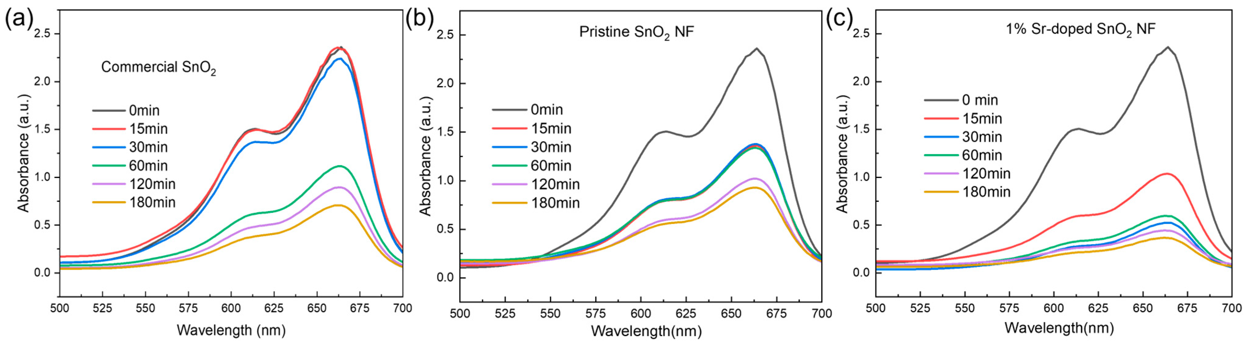
| Sample | % Degradation |
|---|---|
| Commercial SnO2 NP | 16 |
| 0% Sr-doped SnO2 NF | 61 |
| 1% Sr-doped SnO2 NF | 69 |
| 3% Sr-doped SnO2 NF | 58 |
| 5% Sr-doped SnO2 NF | 63 |
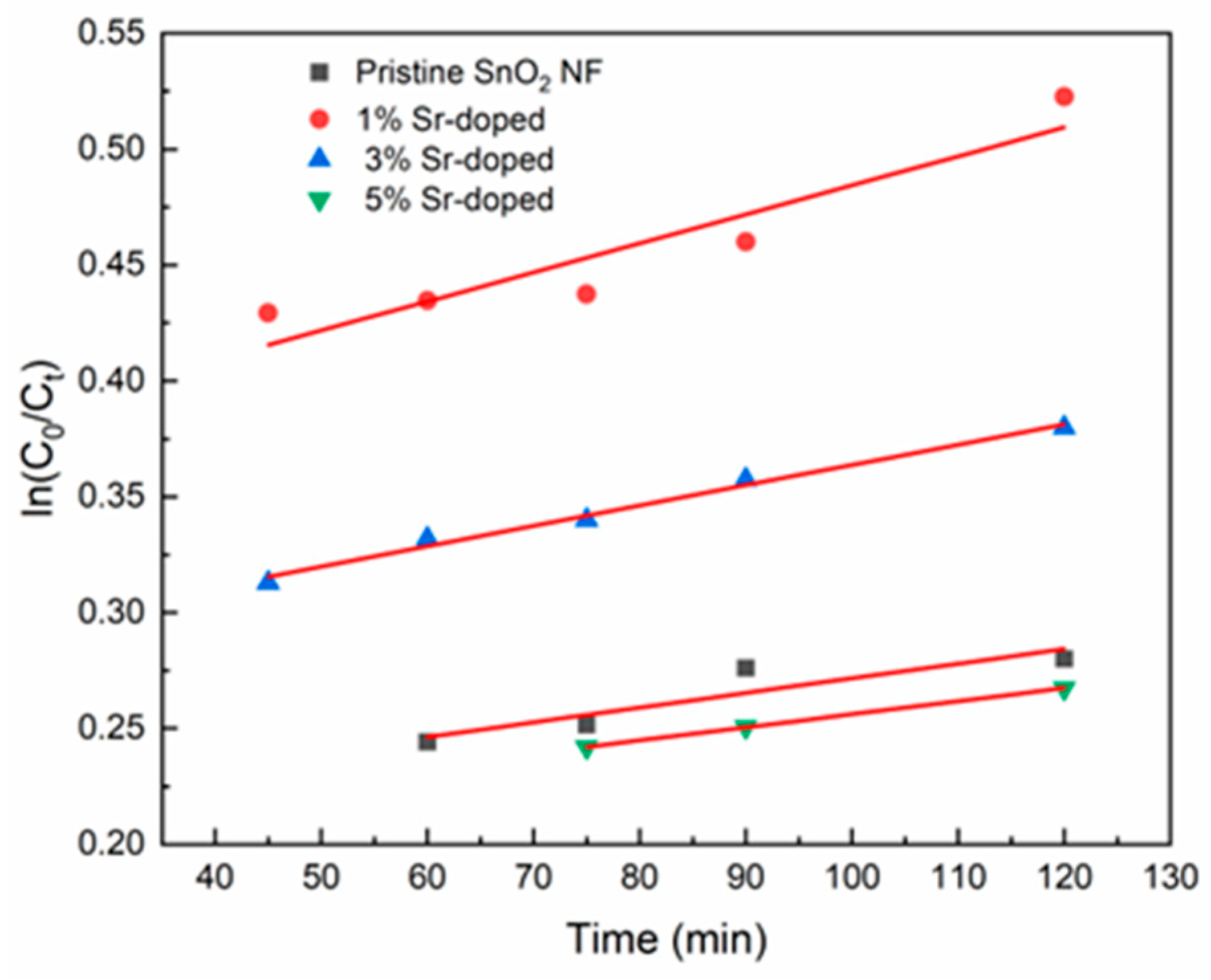
| Sample | Reaction Rate, k (min−1), from 40 to 120 min | R2 |
|---|---|---|
| Pristine SnO2 NF | 6.32 × 10⁻⁴ | 0.83 |
| 1% Sr-doped | 0.00125 | 0.87 |
| 3% Sr-doped | 8.76 × 10⁻⁴ | 0.98 |
| 5% Sr-doped | 5.65 × 10⁻⁴ | 0.99 |
| Sample Name | Commercial SnO2 | 0% Sr-Doped SnO2 NF | 1% Sr-Doped SnO2 NF |
|---|---|---|---|
| % degradation | 70% | 61% | 84.74% |
Disclaimer/Publisher’s Note: The statements, opinions and data contained in all publications are solely those of the individual author(s) and contributor(s) and not of MDPI and/or the editor(s). MDPI and/or the editor(s) disclaim responsibility for any injury to people or property resulting from any ideas, methods, instructions or products referred to in the content. |
© 2025 by the authors. Licensee MDPI, Basel, Switzerland. This article is an open access article distributed under the terms and conditions of the Creative Commons Attribution (CC BY) license (https://creativecommons.org/licenses/by/4.0/).
Share and Cite
Barua, P.; Thai, T.; Krishnan, K.; Elumalai, N.K. Strontium-Doped Tin Oxide Nanofibers for Enhanced Visible Light Photocatalysis. Energies 2025, 18, 2495. https://doi.org/10.3390/en18102495
Barua P, Thai T, Krishnan K, Elumalai NK. Strontium-Doped Tin Oxide Nanofibers for Enhanced Visible Light Photocatalysis. Energies. 2025; 18(10):2495. https://doi.org/10.3390/en18102495
Chicago/Turabian StyleBarua, Pranta, Tan Thai, Kannoorpatti Krishnan, and Naveen Kumar Elumalai. 2025. "Strontium-Doped Tin Oxide Nanofibers for Enhanced Visible Light Photocatalysis" Energies 18, no. 10: 2495. https://doi.org/10.3390/en18102495
APA StyleBarua, P., Thai, T., Krishnan, K., & Elumalai, N. K. (2025). Strontium-Doped Tin Oxide Nanofibers for Enhanced Visible Light Photocatalysis. Energies, 18(10), 2495. https://doi.org/10.3390/en18102495