Article

Energy, Exergic and Economic Analyses of a Novel Hybrid Solar–Gas System for Producing Electrical Power and Cooling

1
Shandong Electric Power Engineering Consulting Institute Co., Ltd., Jinan 250013, China
2
School of Energy and Power Engineering, Northeast Electric Power University, Jilin 132012, China
*
Author to whom correspondence should be addressed.
Energies 2025, 18(10), 2480; https://doi.org/10.3390/en18102480
Submission received: 25 March 2025 / Revised: 26 April 2025 / Accepted: 10 May 2025 / Published: 12 May 2025
(This article belongs to the Section A2: Solar Energy and Photovoltaic Systems)

Abstract

:
This paper aims to evaluate the feasibility and performances of a novel hybrid solar–gas system, which provides electric power and cooling. By using Ebsilon (V15.0) software, the operation, advanced exergic and economic analyses of this hybrid system are conducted. The analysis results show that the total electric power and energy efficiency of the hybrid system are 96.0 MW and 45.8%. The solar energy system contributes an electric power of 9.0 MW. The maximum cooling load is 69.66 MW. The exergic loss and exergic efficiency of the whole hybrid system are 119.1 MW and 44.6%. The combustion chamber (CC) has the maximum exergic loss (56.5 MW). The exergic loss and exergic efficiency of the solar direct steam generator (SDSG) are 28.5 MW and 36.2%. For the air compressor (AC), CC, heat recovery steam generator (HRSG) and refrigeration system (CSS), a considerable part of the exergic loss is exogenous. The avoidable exergic loss of the CC is 11.69 MW. For the SDSG, there is almost no avoidable exergic loss. Economic analysis shows that for the hybrid system, the levelized cost of energy is 0.08125 USD/kWh, and the dynamic recycling cycle is 5.8 years, revealing certain economic feasibility. The results of this paper will contribute to the future research and development of solar–gas hybrid utilization technology to a certain extent.

1. Introduction

To meet the needs of the energy transition, solar energy [1,2,3,4,5] and solar-based multi-energy systems [6,7,8,9,10] have been well studied and developed. By contrast, the integrated solar–gas combined cycle (ISCC) technology is relatively more mature as many related theoretical, simulation and experimental studies have been launched, and thus some different kinds of ISCC systems have been proposed.
The first law of thermodynamics pays more attention to the quantity of energy, the second law of thermodynamics pays more attention to the quality of energy while the exergic analysis can present both the quantity and quality of energy simultaneously. By using the exergic analysis, the exergic destruction and exergic efficiency of every component of a system can be obtained. Therefore, the exergic analysis approach becomes a useful thermodynamic analysis method [11].
The traditional exergic analysis cannot provide information about the mutual influence relationship between system components, and thus it is difficult to identify the real reason for the increase in the irreversible losses of each component. The exergic destruction of a component is not only related to the efficiency of this component, but also affected by other components of the system. Hence, a reasonable exergic analysis process should consider the interaction between the components in the entire system rather than consider a certain component independently. The advanced exergic analysis is developed on the basis of the traditional exergic analysis and considers the actual conditions and unavoidable conditions of different components in the system. It can split the exergic destruction into the endogenous and exogenous parts, or into the avoidable and unavoidable parts. That will reveal the energy-saving potential of each component and provide a reference for improving the system performance. Tsatsaronis, Cziesla, Kelly and some other researchers have developed the methods of splitting exergic destruction into the endogenous and exogenous parts or into avoidable and unavoidable parts [12,13,14,15], which is an important supplement to the traditional exergic analysis method.
Many traditional exergic analysis and advanced exergic analysis studies have been conducted. Ameri et al. [16] carried out the exergic analysis of an ISCC system. They found that the ISCC system had great advantages in thermal performance. Tsatsaronis et al. launched the advanced exergic analyses of gas–steam systems [17], a refrigeration system [18] and some other energy conversion systems [19]. Acikkalp et al. [20] estimated the thermal behavior of a gas-fired power system by using the advanced exergic analysis and exergo-economic analysis methods. Petrakopoulou et al. [21] carried out an advanced exergic analysis of a power plant with chemical looping combustion.
There are also many existing studies on ISCC systems. For instance, Spelling and Laumert [22] conducted the economic analysis of an ISCC system with considering the environmental protection effect. The impact of CO2 emission reduction brought by the usage of solar energy on the economic performance of the ISCC system was evaluated. Achour et al. [23] carried out a performance evaluation of the first ISCC system in Algeria. The results revealed the relatively better operation performance of the evaluated ISCC system compared with a traditional gas–steam turbine combined cycle. Bellos et al. [24] conducted a study on an ISCC system with parabolic trough collectors (PTCs). The results showed that by using solar energy, the ISCC system with the output power of 14.81 MW could reduce the annual fuel consumption by 64.0%.
According to the literature review, though researchers have conducted many studies on design and performance analysis of ISCC systems, advanced exergic analysis studies on ISCC systems are still relatively low, and need further work. This paper presents a novel hybrid solar–gas system. It is designed for power generation and cooling supply. By using the grey-box model and Ebsilon (V15.0) software, the operation, advanced exergic and economic analyses of the hybrid solar–gas system are carried out. The operational performance, exergic and economic parameters of the proposed hybrid solar–gas system are calculated and analyzed. The results of this paper may contribute to the future research and development of hybrid solar–gas systems.

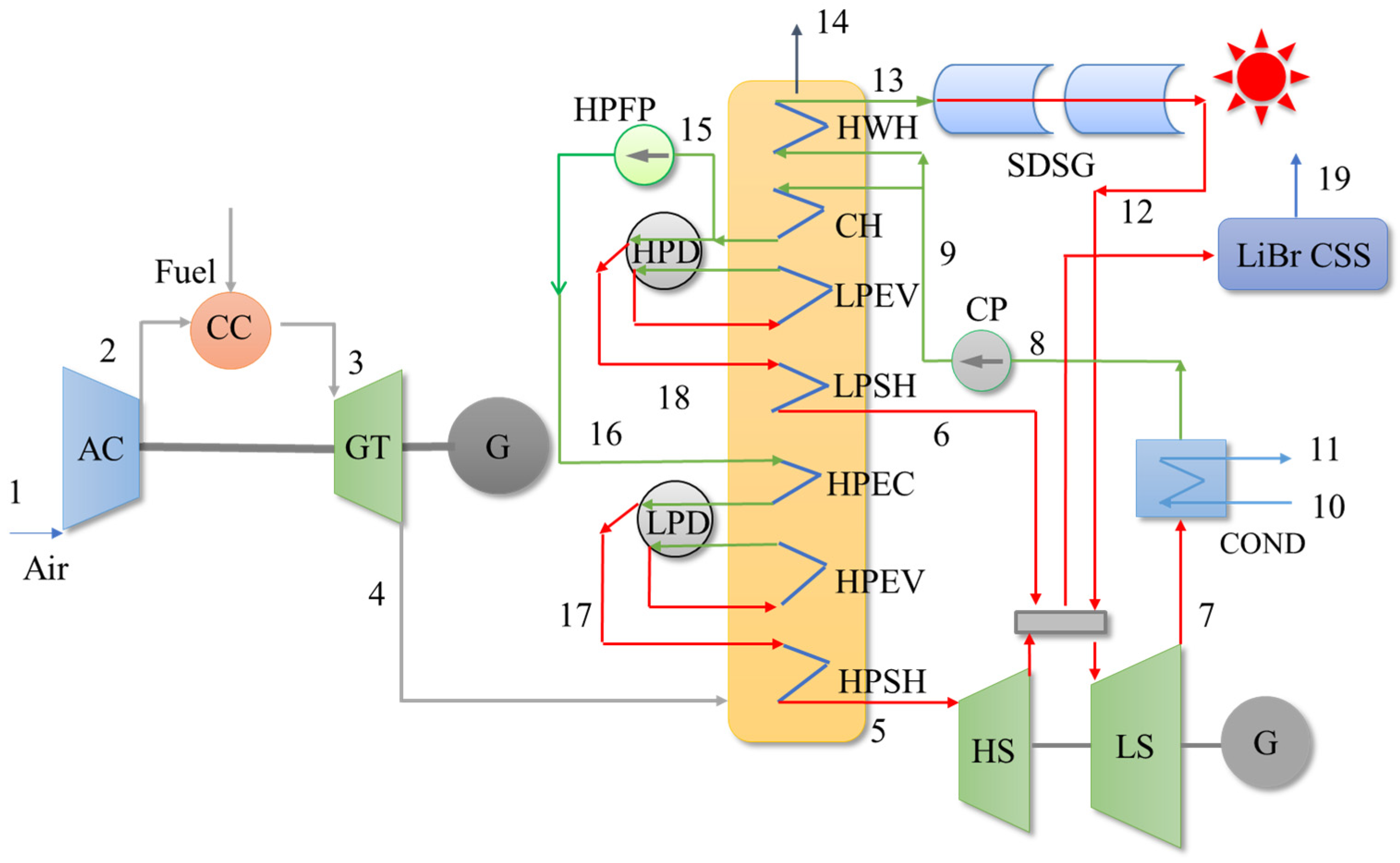
2. Design of the Solar–Gas System

The diagram and working flow of the hybrid solar–gas system are presented in Figure 1. The hybrid solar–gas system is mainly comprised by the solar direct steam generator (SDSG), gas-steam turbine cycle and cooling supply system (CSS). The rated electric power of the hybrid solar–gas system is designed to be 96.0 MW. The SDSG employs PTCs.
In Figure 1, AC, CC and GT stand for the air compressor, combustion chamber and gas turbine. G represents the power generator. HWH, CH, LPEV, LPSH, HPEC, HPEV and HPSH are the hot water heater, condensate heater, low-pressure evaporator, low-pressure super-heater, high-pressure economizer, high-pressure evaporator and high-pressure super-heater, respectively. HPFP is the high-pressure feedwater pump. CP stands for the condensate pump. HPD and LPD are the high-pressure and low-pressure drums. HS and LS are the high-pressure and low-pressure stages of the steam turbine (ST). In this solar–gas system, the super-heated steam generated by the SDSG goes into the low-pressure steam supply pipe (LPSSP) and then drives the LS to generate electric power together with the steam coming from the heat recovery steam generator (HRSG). A stream of super-heated steam is extracted from the LPSSP and then sent to the CSS.

3. Research Methods

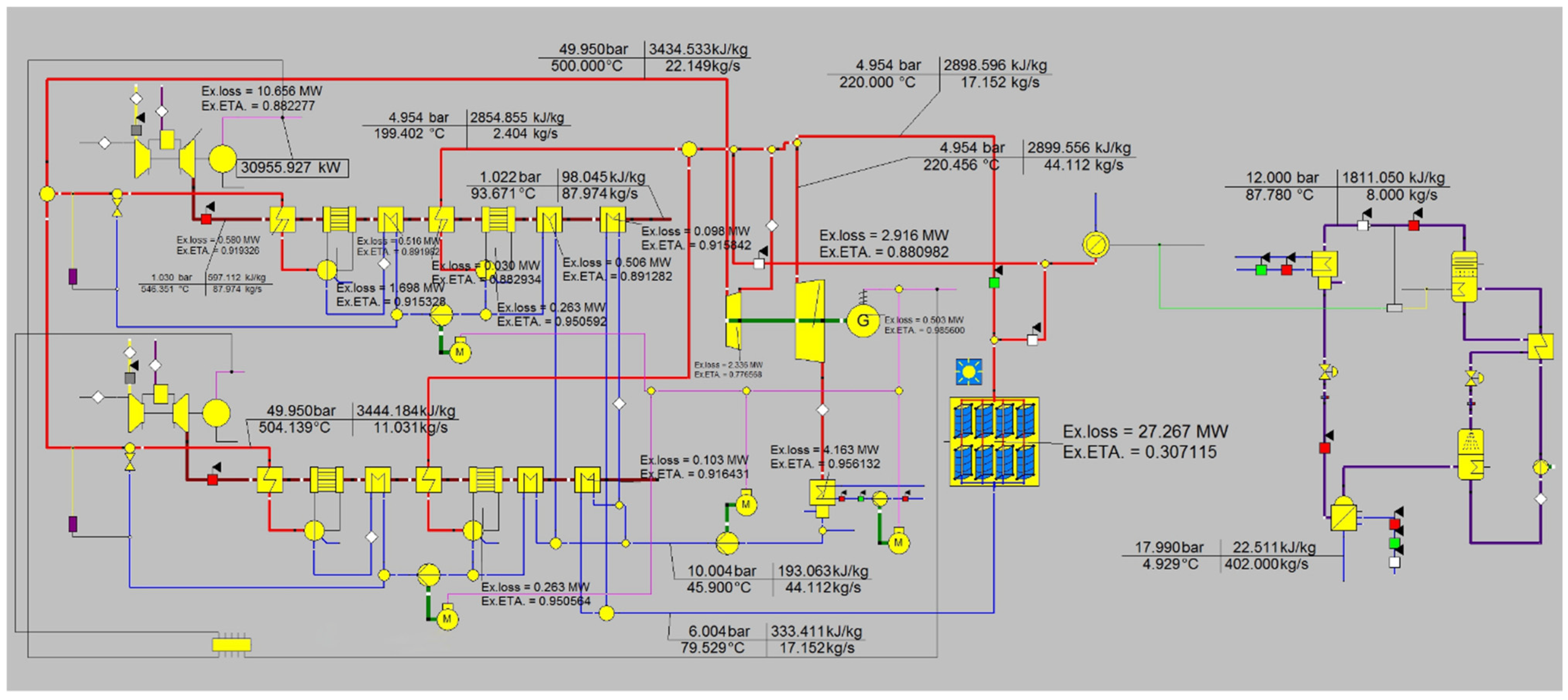
3.1. Modeling Method

According to the working principle and assumed parameters, the simulation model of the hybrid system is built with Ebsilon (V15.0) software. This software is extensively employed in research works related to modeling, simulation and thermodynamics analysis of different power systems. Its serviceability in simulation and analytical works of power systems have been reported by many references.
The simulation model of the hybrid system in this work is presented in Figure 2. The subsequent operation, exergic and economic analyses of the hybrid system are all based on this model.
To validate the ability of the simulation model and Ebsilon (V15.0) software, simulation results of a gas–steam turbine cycle reported by a reference are selected [25]. A gas–steam turbine cycle is newly established by using Ebsilon in this paper and its operation is simulated. The newly obtained simulation results and the referenced results are shown in Table 1. It can be seen from Table 1 that the simulation results and referenced values have relatively good agreement.

3.2. Traditional Exergic Analysis Equations

By establishing the exergic analysis model and then listing the exergy balance equations, the traditional exergic analysis of a system can be conducted. The grey-box mode approach is employed to carry out the traditional exergic analysis of the solar–gas system. This approach considers all components of a system as grey-boxes and connects different grey-boxes with exergy flow lines. There are three exergy variables in an assumed grey-box unit, which are exergy supply Ex+, effective exergy Ex− and exergic loss Ed. Every component of the solar–gas system can be considered as this kind of grey-box unit.
According to the grey-box model, the exergy balance formula is
E d = E x + E x
and the exergic efficiency is
η x = E x / E x + = 1 E d / E x +
Based on the two formulas and Figure 1, the exergic analysis (EA) equations for different components of the solar–gas system are listed below.
For the AC, the two EA equations are
E d , ac = W ac E x 2 + E x 1
η ac = E x 2 / W ac + E x 1
where Wac is the energy consumption of the AC. Ex2 and Ex1 are the outlet and inlet exergy values of the AC.
The EA formulas for the CC are
E d , cc = E x 2 + E fuel E x 3
η cc = E x 3 / E x 2 + E fuel
where Efuel is the exergy of the inlet gas of the CC. Ex3 is the inlet exergy of the ST.
The EA formulas for the GT are
E d , gt = E x 3 E x 4 W gt , out
η gt = W gt , out + E x 4 / E x 3
where Wgt,out is the output power of the GT. Ex4 is the outlet gas exergy of the GT.
For the HRSG and ST, the EA equations are
E d , hrsg = E x 4 E x 5 ( E x 6 E x 9 )
η hrsg = E x 5 + E x 6 / E x 4 + E x 9
E d , st = E x 6 + E x 5 + E x 12 E x 7 W st , out
η st = E x 7 + W st , out / E x 6 + E x 5 + E x 12
where Ex5 is the inlet steam exergy of the HS. Ex6 is the inlet steam exergy of the LS. Ex9 is the inlet feedwater exergy of the HRSG. Ex12 is the exergy of steam coming from the SDSG, which enters the LS. Ex7 is the exhaust gas exergy of the LS. Wst,out is the output power of the ST.
The EA formulas for the condenser and CP are
E d , cond = E x 7 + E x 10 E x 8 + E x 11
η cond = E x 8 + E x 11 / E x 7 + E x 10
E d , cp = W cp , con E x 9 E x 8
η cp = E x 9 / W cp , con + E x 8
where Wcp,con is the power consumption of the CP. Ex8, Ex10 and Ex11 are the exergy values of outlet condensate water, inlet circulating water and outlet circulating water of the condenser.
The EA equations of the SDSG are
E d , sdsg = E x 13 + E x , solar E x 12
η sdsg = E x 12 / E x 13 + E x , solar
where Ex13 is the inlet water exergy of the SDSG. Ex,solar is the solar radiation exergy input of the SDSG, and can be expressed as [26]
E x , solar = 1 4 3 T 0 T s + 1 3 T 0 T s 4
where T0 is the ambient temperature, and Ts is the equivalent temperature of the sun as a black body.
For the HPFP, the EA formulas are
E d , hpfp = W hpfp , con + E x 15 E x 16
η hpfp = E x 16 / W hpfp , con + E x 15
where Whpfp,con is the power consumption of the HPFP. Ex15 and Ex16 are the exergy values of inlet and outlet water of the HPFP.

3.3. Advanced Exergic Analysis Equations

3.3.1. Exergic Loss Splitting

The main target of the traditional exergic analysis is to find the components with relatively large exergic losses or low exergy efficiencies. However, by using the traditional exergic analysis, it is hard to reveal the interactions among the components as well as the optimization potential of the relevant components. For a thermal system, on one hand, the exergic loss cannot exactly describe the performance of a certain component as part of the exergic loss may be related to other components. To deal with this problem, from the perspective of thermodynamics, the advanced exergic analysis approach splits the total exergic loss of a certain component into the endogenous and exogenous parts. On the other hand, due to some unavoidable factors (e.g., technical, material, economic limitations), a component has a part of exergic loss which cannot be optimized and decreased. To reflect the potential of energy saving of this component, from the perspective of engineering, the advanced exergic analysis approach splits the total exergic loss of a certain component into the avoidable and unavoidable parts.
The exergic loss splitting of a certain component is illustrated in Figure 3. Ed is the total exergic loss. Ed,en and Ed,ex are the endogenous and exogenous exergic losses. Ed,av and Ed,un are the avoidable and unavoidable exergic losses.

3.3.2. Equation of Endogenous and Exogenous Exergic Losses

For a certain component, its endogenous exergic loss is related to its own performance and operation state, while its exogenous exergic loss is caused by the inefficient operations of some other components. The total exergic loss of the component is the sum of the endogenous and exogenous exergic losses. Hence, there is
E d = E d , en + E d , ex
In this study, the endogenous and exogenous exergic losses of different components of the solar–gas combined system are calculated by using the exergy balance approach [27]. When the exergy balance approach is used for calculating the endogenous and exogenous exergic losses, a simulation model should be established. In this study, Ebsilon is utilized to establish the simulation models of the components of the solar–gas combined system. When the advanced exergic analysis of a certain component is conducted, the exergy balance approach needs to idealize other components firstly, and then the component’s isentropic efficiency, pressure drop and some other parameters should be changed. The detailed implementation steps of the exergy balance approach can be seen in the relevant references [27].

3.3.3. Equation of Avoidable and Unavoidable Exergic Losses

The analysis of avoidable exergic loss is beneficial to improving the performance of a thermal system. The unavoidable exergic loss is defined as the smallest exergic loss due to the limitations of technology, materials, manufacturing processes and economic conditions. The avoidable exergic loss is the difference between the total exergic loss and unavoidable part, and there is
E d = E d , av + E d , un
To calculate the unavoidable exergic loss of a certain component, the component should be isolated from other components of the system firstly, and then be artificially given a relatively reasonable and achievable efficiency according to the existing operation experience. After calculating the ratio of exergic loss and exergy production under the unavoidable condition, the avoidable exergic loss can be obtained. The parameter settings for typical components under the ideal and unavoidable conditions are shown in Table 2 [28,29]. The parameters in Table 2 are used for the calculations and analyses of avoidable and unavoidable exergic losses, and not for the operation performance simulation of the hybrid system.

3.4. Economic Analysis Equations

For the hybrid system, its levelized cost of energy (LCOE) is [30]
L C O E = r dis C tot + F O M C + C y , fuel C carbon M y + V O M C
where Ctot is the total construction cost of the hybrid system. FOMC and VOMC are the fixed and varying operation and maintenance costs. Cy,fuel and My are the annual fuel cost and annual electric power generation of the hybrid system. Ccarbon is the income brought by the CO2 emission reduction. rdis is the discount rate. The annual income (INy) of the hybrid system is
I N y = M y × e grid
where egird is the on-grid electricity price. The net present value of the hybrid system is
C net = t = 0 n I N y F O M C 1 + r dis t
where n is the lifetime of the hybrid system.

4. Results and Discussion

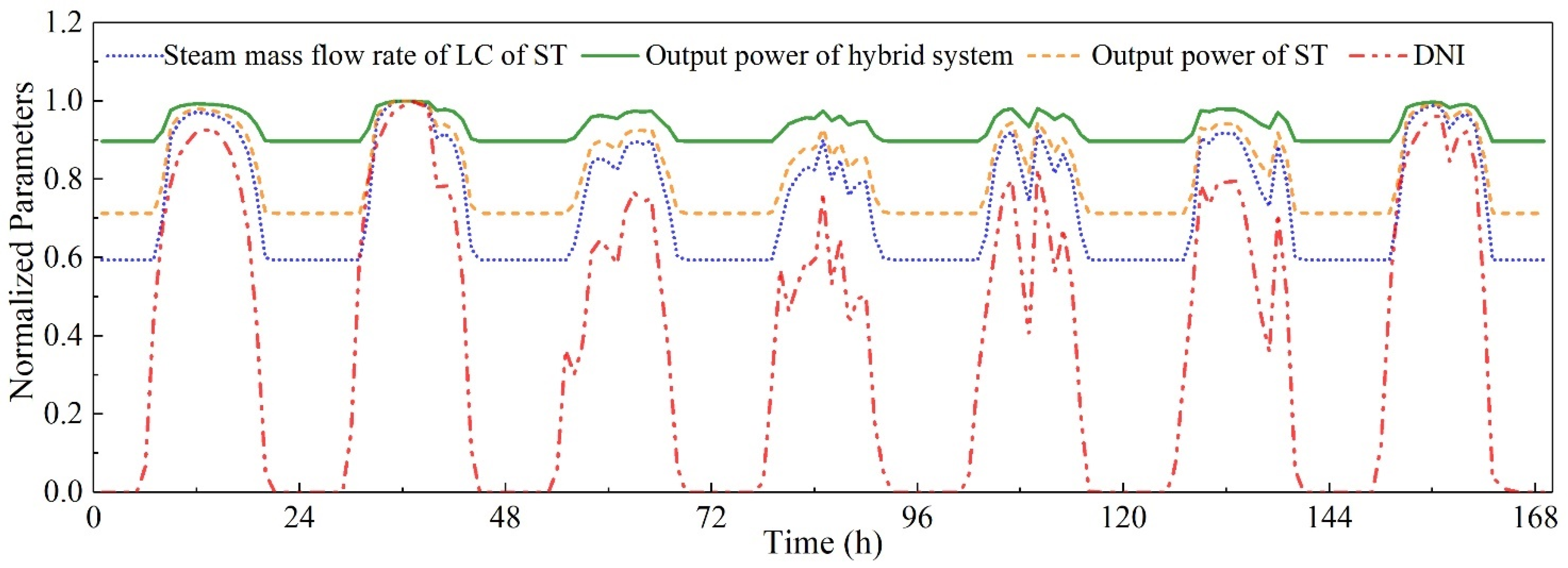
4.1. Operation Performance

Setting the incident solar intensity as 900.0 W/m2, the operation process of the hybrid system is simulated by using Ebsilon (V15.0) software. The main operation parameters of the solar–gas system are shown in Table 3. In Table 3, the initial parameters for operation simulations are obtained from the relevant reference [25], and operation performance parameters of the hybrid system are obtained from Ebsilon-based simulations in this study. The results show that the electric power and energy conversion efficiency of the hybrid system are 96.0 MW and 45.8%. The electric power of gas–steam cycle is 87.0 MW, and that contributed by the SDSG system is 9.0 MW. Therefore, the solar energy proportion of the hybrid system is 9.4%. The maximum cooling load of the hybrid system is 69.66 MW.
Effects of some key parameters on the operation performance of the hybrid solar–gas system are analyzed. Figure 4 presents the output power and energy conversion efficiency variations of the hybrid system when the incident solar intensity changes. As shown in Figure 4, when the incident solar intensity increased from 300.0 W/m2 to 1000.0 W/m2, the output power of the hybrid system increased from 89.6 MW to 97.1 MW, but the energy conversion efficiency decreased from 49.9% to 45.2%. That is mainly because the increase in the incident solar intensity improves the electric power contributed by solar energy, but the thermal-to-electric efficiency of solar energy is lower than the electric efficiency of the gas–steam turbine combined cycle.
Figure 5 presents the output power and energy conversion efficiency variations of the hybrid system when the ambient temperature changes. The results show that when the ambient temperature increased from −5.0 °C to 30.0 °C, the output power and energy conversion efficiency of the hybrid system both increase first and then decrease. When the ambient temperature is 10.0 °C, the hybrid system has both the maximum output power and maximum energy conversion efficiency (96.6 MW and 46.5%). This is mainly because 10.0 °C is the optimal ambient temperature value for the AC and CC. That is due to the operation characteristics of the gas–steam turbine combined cycle of the hybrid system.
In addition, the analysis results show that when the efficiency of the CC is low, the combustion of fuel will be insufficient. This will reduce the power output of the GT, decrease the exhaust temperature of the GT and thus reduce the heat absorption of the HRSG. Finally, the cooling capacity of the refrigeration system will decrease. Under the same refrigeration condition, if the efficiency of the refrigeration system decreases, the demand for steam in the refrigeration system will increase. In this way, the steam sent to the LS will be reduced, thereby making the output power of the hybrid system decrease.
Figure 6 shows the seven-day continuous operation simulation results of the hybrid system when the incident solar intensity changes. The results indicate that the SDSG system and gas–steam cycle can effectively work together. The coordinated operation of the SDSG system and gas–steam cycle can be realized, showing the technical feasibility of the hybrid system to a certain extent.

4.2. Traditional Exergic Analysis

The traditional exergic analysis results of the hybrid solar–gas system are presented in Table 4. In Table 4, COND and GEN stand for the condenser and power generator, and other abbreviations can be seen in the Nomenclature section. According to the traditional exergic analysis results, the exergic loss and exergic efficiency of the whole hybrid solar–gas system are 119.1 MW and 44.6%, respectively.
Among all components of the hybrid system, the CC has the maximum exergic loss, which is 56.5 MW. The exergic efficiency of the CC is about 62.0%. Another component with large exergic loss is the SDSG, and its exergic loss and exergic efficiency are 28.5 MW and 36.2%. According to these results, it can be concluded that the CC and SDSG both have certain optimization potential. The CSS has the lowest exergic efficiency, which is 24.6%. The exergic loss of the CSS is 8.3 MW. However, as the main function of the CSS is to use the low-grade thermal energy to provide cooling, the economy of the CSS cannot simply be estimated by using the exergic analysis results.

4.3. Advanced Exergic Analysis

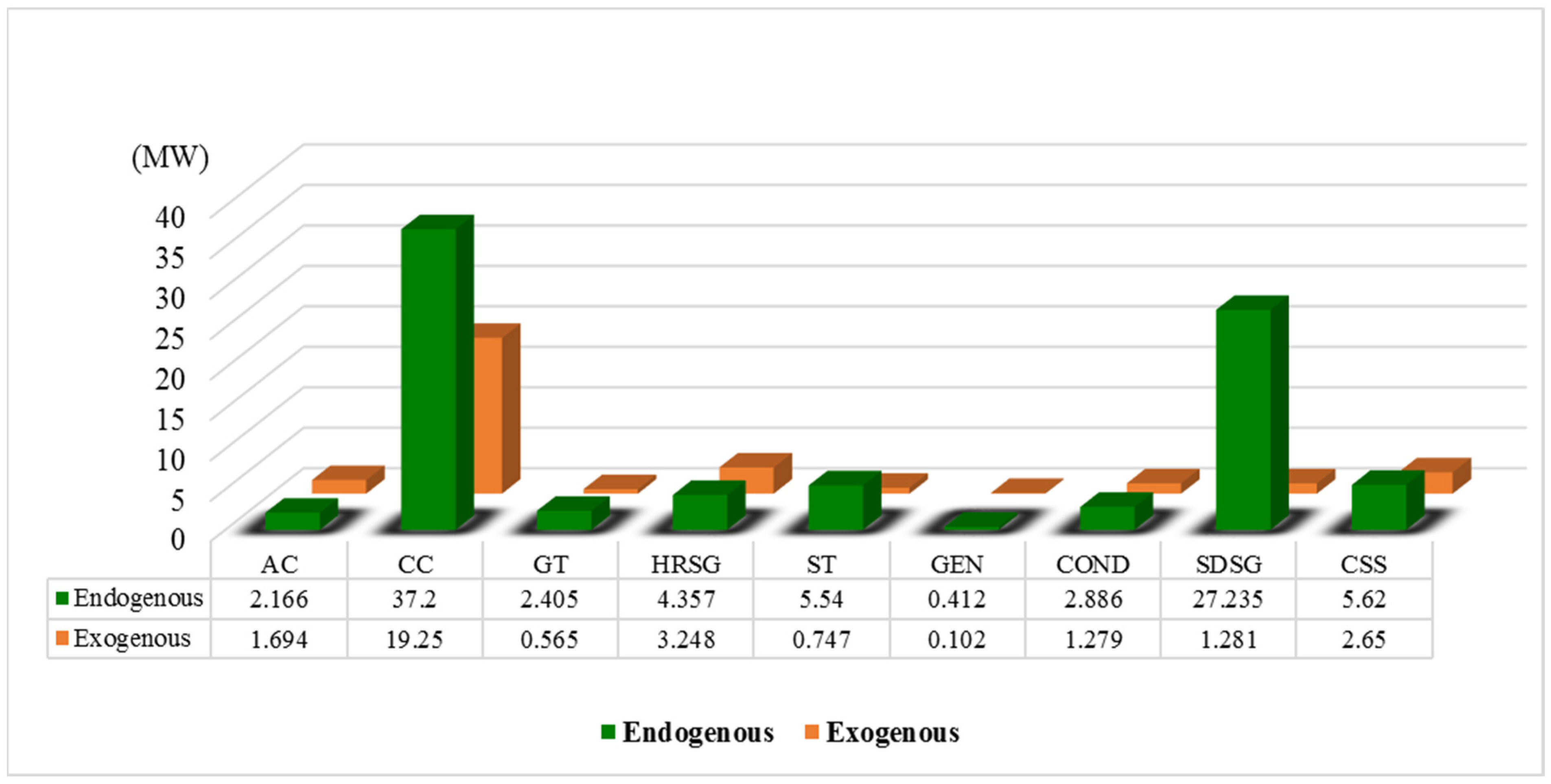
4.3.1. Endogenous and Exogenous Exergic Losses

This section presents the analysis results of endogenous and exogenous exergic losses of the solar–gas system. The exergy balance approach is employed and the ideal state parameters of different components for the calculations of endogenous and exogenous exergic losses are presented in Table 5. The nodes in Table 5 are corresponding to those presented in Figure 1.
For the endogenous and exogenous exergic loss calculations of different components, some assumptions are adopted. For instance, the isentropic efficiency and mechanical efficiency of the AC are set to be 1.0. To minimize the exergic loss of the HRSG, the pressure drops of all heat exchangers in the HRSG are set to be 0.0. For the ST, GT and power generators, their isentropic efficiency and mechanical efficiency are all set to be 1.0. For the CC, its ideal state is difficult to be defined as chemical reactions happened in it. This study adopts the ideal assumptions of the CC presented in Ref. [31]. It is assumed that under the ideal state, the composition of the outlet gas of the CC is consistent with that under the actual state, the combustion efficiency of the CC is 1.0, the pressure drop of the CC is 0.0 and the excess air coefficient is the same as that under the actual state. The advanced exergic analysis results of different components are provided in Figure 7 and Table 6.
In Table 6, ken is the ratio of the endogenous exergic loss to the total exergic loss. According to Figure 7 and Table 6, the endogenous exergic losses of the AC, CC, HRSG and CSS are 2.166 MW, 37.2 MW, 4.357 MW and 5.62 MW, and the corresponding exogenous exergic losses are 1.694 MW, 19.25 MW, 3.248 MW and 2.65 MW, respectively. For the four components, a considerable part of the exergic loss is exogenous. Their endogenous exergic loss proportions are 0.561, 0.659, 0.573 and 0.680. For the SDSG, 95.5% of the total exergic loss is endogenous. That is because the SDSG is relatively independent and slightly affected by other components of the solar–gas system.

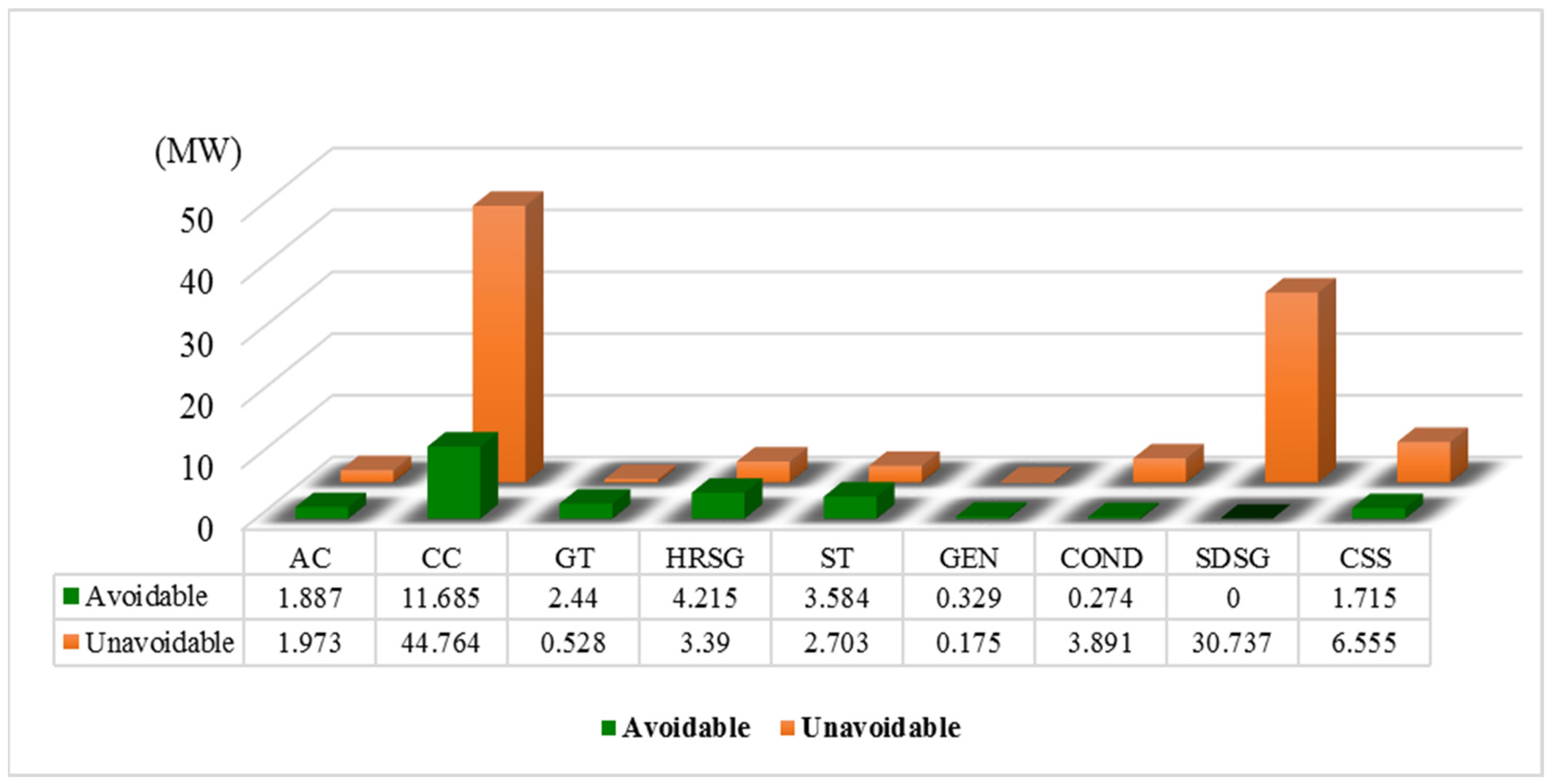
4.3.2. Avoidable and Unavoidable Exergic Losses

For the calculation of avoidable and unavoidable exergic losses of different components of the solar–gas system, the parameter settings for typical components under the ideal and unavoidable conditions are shown in Table 2 (see Section 3.3.3). The calculation results of avoidable and unavoidable exergic losses of typical components of the solar–gas system are presented in Figure 8 and Table 7.
As shown in Figure 8 and Table 7, the avoidable exergic loss proportion of the SDSG is the lowest, which is 0.003. That means there is almost no avoidable exergic loss in the SDSG under the current condition. For the AC, CC, GT, HRSG, ST, GEN and CSS, a considerable part of the exergic loss is avoidable. The avoidable exergic loss of the CC is the maximum (about 11.69 MW). The avoidable exergic losses of the AC, GT, HRSG and ST are 1.89 MW, 2.44 MW, 4.22 MW and 3.58 MW. For these components (especially for the CC), there is still certain optimization potential according to the advanced exergic analysis results.
Advanced exergic analysis results have practical implications for the studied hybrid solar–gas system. The above advanced exergic analysis results have demonstrated endogenous, exogenous, avoidable and unavoidable exergic losses for different components. Based on these results, in the design stage of the hybrid system, it is possible to identify components with avoidable exergic loss and optimize their design accordingly. For the components with very small avoidable exergic loss, more concern should be given on their materials and manufacturing processes. That can improve the efficiency of practical design optimization work of the hybrid system. Taking the SDSG as the example, the SDSG has large exergic loss. However, most of the exergic loss of the SDSG is unavoidable. Therefore, to reduce the exergic loss of the SDSG, material selection improvement of solar collectors should be conducted. For instance, reflector materials with higher reflectivity should be used, and receiver tube surface-coating materials with higher absorptivity and lower emissivity should be explored.

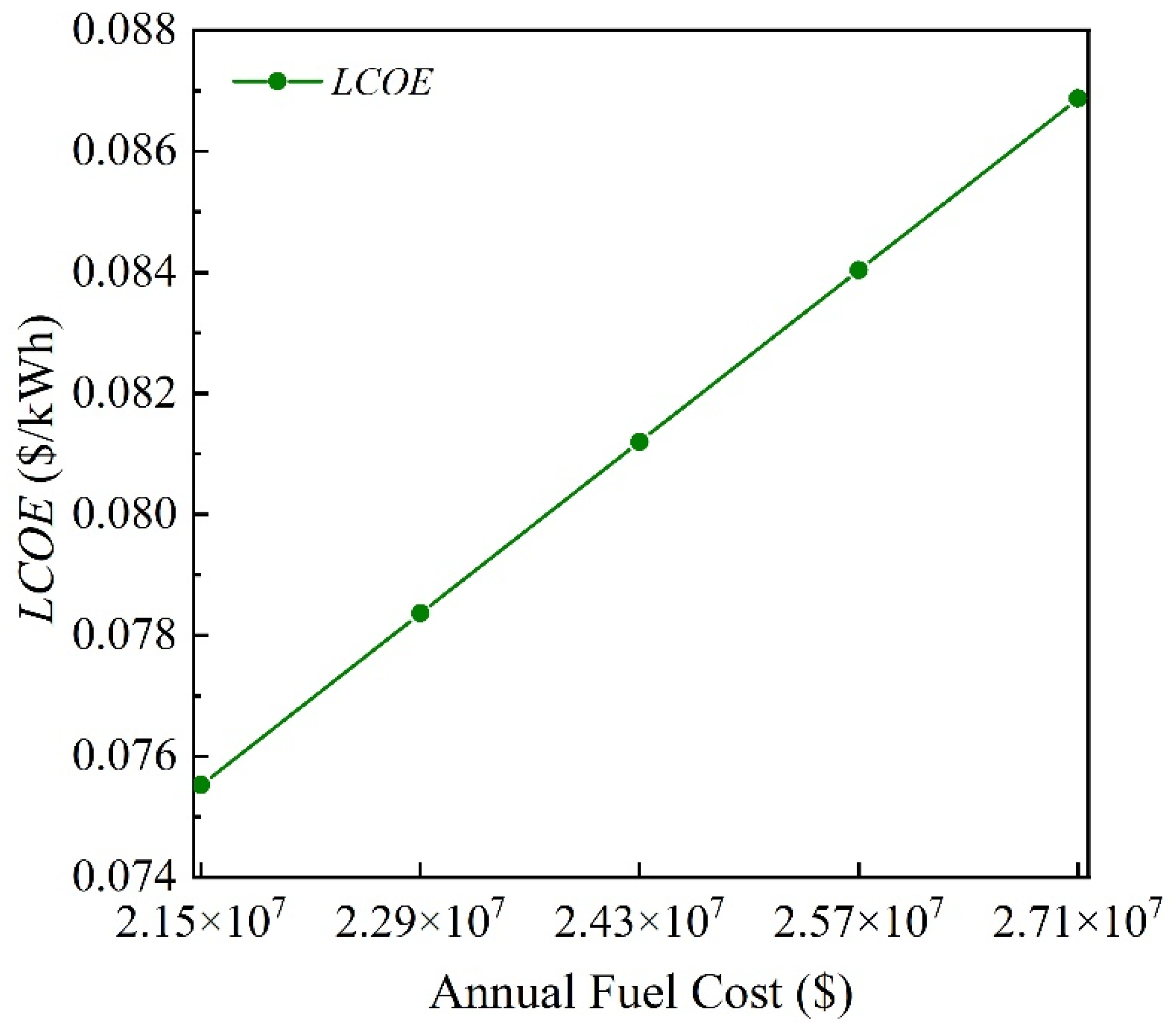
4.4. Economic Analysis

For the economic analysis, the annual operation of the hybrid solar–gas system is simulated by using the solar radiation data of a typical city for a typical year. The exchange rate between the US dollar (USD) and the Chinese yuan (CNY) is 7.2. For the hybrid solar–gas system, the annual electric power generation is 489,600.0 MWh, and this value is obtained from the annual operation simulation of the hybrid system. The discount rate is chosen to be 0.1 [32]. Based on Ref. [33], the total construction cost of the hybrid system is USD 44,084,166.7, and the annual operation and maintenance cost is USD 1,445,972.2. According to Ref. [25], the annual fuel cost is USD 24,329,861.1, and the income brought by the CO2 emission reduction is USD 1,165,555.6. The lifetime of the hybrid system is 30.0 years, and the on-grid electricity price is 0.10417 USD/kWh. The economic analysis results of the hybrid system are presented in Table 8.
The results indicate that for the hybrid solar–gas system, the levelized cost of energy is 0.08125 USD/kWh. The dynamic recycling cycle is 5.8 years. The net present value is about USD 61.48 million, and the internal rate of return is 18.3%. These results reveal the relatively presentable economic feasibility of the hybrid system. Figure 9 presents the variation of LCOE of the hybrid system when the annual fuel cost changes. The results show that with the annual fuel cost increased from 2.15 × 10⁷ USD to 2.71 × 10⁷ USD, LCOE of the hybrid system increases from 0.07553 USD/kWh to 0.08687 USD/kWh.
Table 9 presents a brief comparison between the hybrid solar–gas system of this study and several other typical ISCC systems. As shown in Table 9, different ISCC systems may have different operation, exergic and economic performances due to their different system compositions and different investment and operation cost conditions. However, the mostly used solar field type in ISCC systems is PTC.

5. Conclusions

In this study, a novel hybrid solar–gas system for electricity production and cooling supply is proposed. Its electric power and energy conversion efficiency are 96.0 MW and 45.8%. The maximum cooling load is 69.66 MW. The solar energy proportion in the hybrid system is 9.4%. The advanced exergic analysis of the hybrid system is conducted. The results show that the total exergic loss and exergic efficiency of the hybrid solar–gas system are 119.1 MW and 44.6%. In the hybrid system, the CC has the maximum exergic loss (56.5 MW). The exergic loss and exergic efficiency of the SDSG are 28.5 MW and 36.2%. However, there is almost no avoidable exergic loss in the SDSG. For the AC, CC, GT, HRSG, ST, GEN and CSS, a considerable part of the exergic loss is avoidable. Especially, the avoidable exergic loss of the CC is the maximum (11.69 MW). For these components, there is still certain optimization potential. The advanced exergic analysis results make the thermodynamic performance of the hybrid system deeply understood. The advanced exergic analysis provides more specific references for the practical component optimizations of the hybrid system. The economic analysis results show that for the hybrid system, the levelized cost of energy is 0.08125 USD/kWh, the dynamic recycling cycle is 5.8 years, and the net present value is USD 61.48 million.
There are still some limitations and further works for this study. For instance, designs and performance comparison works on the hybrid solar–gas system with different types of solar collectors will be meaningful. In addition, the multi-objective optimization comprehensively considering operation performance and economic parameters on the hybrid system should be conducted in the next step.

Author Contributions

Writing—original draft, Q.G., X.C. and F.G.; Writing—review & editing, J.L., C.W. and G.W. All authors have read and agreed to the published version of the manuscript.

Funding

The authors appreciate the support of the Science and Technology Projects of Shandong Electric Power Engineering Consulting Institute Corporation Limited (Grant No. 37-K2024-208).

Data Availability Statement

The original contributions presented in this study are included in the article. Further inquiries can be directed to the corresponding author.

Conflicts of Interest

Authors Qun Ge, Xiaoman Cao, Fumin Guo, Jianpeng Li and Cheng Wang were employed by the company Shandong Electric Power Engineering Consulting Institute Co., Ltd. The remaining author declares that the research was conducted in the absence of any commercial or financial relationships that could be construed as a potential conflict of interest. The authors declare that this study received funding from Shandong Electric Power Engineering Consulting Institute Co., Ltd. The funder had the following involvement with the study: system design, analysis, interpretation of data, the writing of this article and the decision to submit it for publication.

Nomenclature

CCost or income (USD)
egirdOn-grid electricity price (USD/kwh)
EdExergic loss (MW)
Ex,solarSolar radiation exergy input of the SDSG (MW)
INyAnnual income (USD)
kProportion (-)
LCOELevelized cost of energy (USD/kwh)
MyAnnual electric power generation (kwh)
rdisDiscount rate (-)
WPower (MW)
Greek symbols
ηExergic efficiency (-)
Subscripts
avAvoidable
dExergic loss
enEndogenous
exExogenous
fomFixed operation and maintenance
outOutput
unUnavoidable
vomVarying operation and maintenance
xExergic
yAnnual
Abbreviation
ACAir compressor
CCCombustion chamber
CHCondensate heater
CPCondensate pump
CONDCondenser
CSSCooling supply system
GENPower generator
GTGas turbine
HPDHigh-pressure drum
HPECHigh-pressure economizer
HPEVHigh-pressure evaporator
HPFPHigh-pressure feedwater pump
HPSHHigh-pressure super-heater
HRSGHeat recovery steam generator
HSHigh pressure stages of the steam turbine
HWHHot water heater
ISCCIntegrated solar–gas combined cycle
LPDLow-pressure drum
LPEVLow-pressure evaporator
LPSHLow-pressure super-heater
LPSSPLow-pressure steam supply pipe
LSLow-pressure stages of the steam turbine
PTCParabolic trough collector
SDSGSolar direct steam generator
STSteam turbine

References

  1. Mokhtar, G.; Boussad, B.; Noureddine, S. A linear Fresnel reflector as a solar system for heating water: Theoretical and experimental study. Case Stud. Therm. Eng. 2016, 8, 176–186. [Google Scholar] [CrossRef]
  2. Wang, G.; Zhang, S.; Zou, T. Design and comparison study of a novel linear Fresnel reflector solar ORC-driven hydrogen production system using different working fluids. Case Stud. Therm. Eng. 2025, 71, 106187. [Google Scholar] [CrossRef]
  3. Wang, G.; Liu, J.; Cao, Y.; Chen, Z. Design and performance estimation of a novel solar multiplate mirror concentration PVT system based on nanofluid spectral filter. Renew. Energy 2024, 235, 121321. [Google Scholar] [CrossRef]
  4. Wang, G.; Chao, Y.; Chen, Z. Promoting developments of hydrogen powered vehicle and solar PV hydrogen production in China: A study based on evolutionary game theory method. Energy 2021, 237, 121649. [Google Scholar] [CrossRef]
  5. Wang, G.; Liu, J. Design and performance evaluation of a novel photovoltaic and concentrated solar thermal system using parabolic trough-shaped spectrum filter. Energy Sources Part A Recovery Util. Environ. Eff. 2025, 47, 6918–6933. [Google Scholar] [CrossRef]
  6. Srinivas, T.; Reddy, B.V. Hybrid solar–biomass power plant without energy storage. Case Stud. Therm. Eng. 2014, 2, 75–81. [Google Scholar] [CrossRef]
  7. Hong, H.; Peng, S.; Zhao, Y.; Liu, Q.; Jin, H. A Typical Solar-coal Hybrid Power Plant in China. Energy Procedia 2014, 49, 1777–1783. [Google Scholar] [CrossRef]
  8. Wang, G.; Zhang, Z.; Lin, J. Multi-energy complementary power systems based on solar energy: A review. Renew. Sustain. Energy Rev. 2024, 199, 114464. [Google Scholar] [CrossRef]
  9. Khare, V.; Nema, S.; Baredar, P. Solar–wind hybrid renewable energy system: A review. Renew. Sustain. Energy Rev. 2016, 58, 23–33. [Google Scholar] [CrossRef]
  10. Wang, G.; Wang, C.; Chen, Z.; Hu, P. Design and performance evaluation of an innovative solar-nuclear complementarity power system using the S-CO2 Brayton cycle. Energy 2020, 197, 117282. [Google Scholar] [CrossRef]
  11. Nezammahalleh, H. Exergy analysis of DSG parabolic trough collectors for the optimal integration with a combined cycle. Int. J. Exergy 2015, 16, 72–96. [Google Scholar] [CrossRef]
  12. Tsatsaronis, G.; Park, M.H. On avoidable and unavoidable exergy destructions and investment costs in thermal systems. Energy Convers. Manag. 2002, 43, 1259–1270. [Google Scholar] [CrossRef]
  13. Tsatsaronis, G.; Kelly, S.O.; Morosuk, T.V. Endogenous and Exogenous Exergy Destruction in Thermal Systems. In Proceedings of the ASME 2006 International Mechanical Engineering Congress and Exposition, Chicago, IL, USA, 5–10 November 2006. [Google Scholar]
  14. Cziesla, F.; Tsatsaronis, G.; Gao, Z. Avoidable thermodynamic inefficiencies and costs in an externally fired combined cycle power plant. Energy 2006, 31, 1472–1489. [Google Scholar] [CrossRef]
  15. Kelly, S.; Tsatsaronis, G.; Morosuk, T. Advanced exergetic analysis: Approaches for splitting the exergy destruction into endogenous and exogenous parts. Energy 2009, 34, 384–391. [Google Scholar] [CrossRef]
  16. Ameri, M.; Mohammadzadeh, M. Thermodynamic, thermoeconomic and life cycle assessment of a novel integrated solar combined cycle (ISCC) power plant. Sustain. Energy Technol. Assess. 2018, 27, 192–205. [Google Scholar] [CrossRef]
  17. Tsatsaronis, G.; Morosuk, T. Advanced exergetic analysis of a novel system for generating electricity and vaporizing liquefied natural gas. Energy 2010, 35, 820–829. [Google Scholar] [CrossRef]
  18. Morosuk, T.; Tsatsaronis, G. Advanced exergetic evaluation of refrigeration machines using different working fluids. Energy 2009, 34, 2248–2258. [Google Scholar] [CrossRef]
  19. Penkuhn, M.; Tsatsaronis, G. A decomposition method for the evaluation of component interactions in energy conversion systems for application to advanced exergy-based analyses. Energy 2017, 133, 388–403. [Google Scholar] [CrossRef]
  20. Acikkalp, E.; Aras, H.; Hepbasli, A. Advanced exergoeconomic analysis of an electricity-generating facility that operates with natural gas. Energy Convers. Manag. 2014, 78, 452–460. [Google Scholar] [CrossRef]
  21. Petrakopoulou, F.; Tsatsaronis, G.; Morosuk, T. Evaluation of a power plant with chemical looping combustion using an advanced exergoeconomic analysis. Sustain. Energy Technol. Assess. 2013, 3, 9–16. [Google Scholar] [CrossRef]
  22. Spelling, J.; Laumert, B. Thermo-economic Evaluation of Solar Thermal and Photovoltaic Hybridization Options for Combined-Cycle Power Plants. J. Eng. Gas Turbines Power 2015, 137, 031801. [Google Scholar] [CrossRef]
  23. Achour, L.; Bouharkat, M.; Behar, O. Performance assessment of an integrated solar combined cycle in the southern of Algeria. Energy Rep. 2018, 4, 207–217. [Google Scholar] [CrossRef]
  24. Bellos, E.; Tzivanidis, C.; Antonopoulos, K.A. Parametric analysis and optimization of a solar assisted gas turbine. Energy Convers. Manag. 2017, 139, 151–165. [Google Scholar] [CrossRef]
  25. Wang, S. Exergy Analysis and Operation Behavior Study of Solar-Gas Combined Cycle System. Master’s Thesis, Northeast Electric Power University, Jilin, China, 2022. [Google Scholar]
  26. Wang, S.; Fu, Z. Thermodynamic Investigation of an Integrated Solar Combined Cycle with an ORC System. Entropy 2019, 21, 428. [Google Scholar] [CrossRef]
  27. Anvari, S.; Saray, R.K.; Bahlouli, K. Conventional and advanced exergetic and exergoeconomic analyses applied to a tri-generation cycle for heat, cold and power production. Energy 2015, 91, 925–939. [Google Scholar] [CrossRef]
  28. Wang, S.; Fu, Z.; Zhang, G.; Zhang, T. Advanced Thermodynamic Analysis Applied to an Integrated Solar Combined Cycle System. Energies 2018, 11, 1574. [Google Scholar] [CrossRef]
  29. Al-Sulaiman, F.A. Exergy analysis of parabolic trough solar collectors integrated with combined steam and organic Rankine cycles. Energy Convers. Manag. 2014, 77, 441–449. [Google Scholar] [CrossRef]
  30. Lorenczik, S.; Keppler, J.H. Projected Costs of Generating Electricity; International Energy Agency: Paris, France, 2020.
  31. Morosuk, T.; Tsatsaronis, G. Advanced Exergy Analysis for Chemically Reacting Systems—Application to a Simple Open Gas-Turbine System. Int. J. Thermodyn. 2009, 12, 105–111. [Google Scholar]
  32. Adibhatla, S.; Kaushik, S.C. Energy, exergy and economic (3E) analysis of integrated solar direct steam generation combined cycle power plant. Sustain. Energy Technol. Assess. 2017, 20, 88–97. [Google Scholar] [CrossRef]
  33. Roosen, P.; Uhlenbruck, S.; Lucas, K. Pareto optimization of a combined cycle power system as a decision support tool for trading off investment vs. operating costs. Int. J. Therm. Sci. 2003, 42, 553–560. [Google Scholar] [CrossRef]
  34. Zhang, P.; Liu, M.; Hu, W.; Chong, D.; Yan, J. System design and thermo-economic analysis of a novel gas turbine combined cycle co-driven by methanol and solar energy. Appl. Energy 2025, 380, 125030. [Google Scholar] [CrossRef]
  35. Baghernejad, A.; Yaghoubi, M. Exergy analysis of an integrated solar combined cycle system. Renew. Energy 2010, 35, 2157–2164. [Google Scholar] [CrossRef]
  36. Benabdellah, H.M.; Ghenaiet, A. Energy, exergy, and economic analysis of an integrated solar combined cycle power plant. Eng. Rep. 2021, 3, e12404. [Google Scholar] [CrossRef]
Figure 1. Diagram and working flow of the solar–gas system.
Energies 18 02480 g001
Figure 2. Simulation model of the solar–gas system.
Energies 18 02480 g002
Figure 3. Exergic loss splitting of a certain component.
Energies 18 02480 g003
Figure 4. Output power and energy conversion efficiency variations of the hybrid system when the incident solar intensity changes.
Energies 18 02480 g004
Figure 5. Output power and energy conversion efficiency variations of the hybrid system when the ambient temperature changes.
Energies 18 02480 g005
Figure 6. Continuous operation performance of the hybrid system.
Energies 18 02480 g006
Figure 7. Endogenous and exogenous exergic losses of different components.
Energies 18 02480 g007
Figure 8. Avoidable and unavoidable exergic losses of different components.
Energies 18 02480 g008
Figure 9. Variation of LCOE of the hybrid system when the annual fuel cost changes.
Energies 18 02480 g009
Table 1. Validation results of the simulation model and Ebsilon (V15.0) software.
ParametersReferenced ValuesResults in This Study
Total electric power/MW87.086.98
Electric power of GT/MW31.030.95
Electric power of ST/MW25.025.10
Exhaust gas temperature/°C546.0546.35
High-pressure steam mass flow rate/t/h80.079.75
High-pressure steam temperature/°C500.0500.0
High-pressure steam pressure/MPa5.04.95
Low-pressure steam mass flow rate/t/h17.017.26
Low-pressure steam temperature/°C200.0199.65
Low-pressure steam pressure/MPa0.50.5
Table 2. Parameters for hybrid solar–gas system components under different conditions.
ComponentIdeal ConditionUnavoidable Condition
ACIsentropic efficiency = 100.0%
Mechanical efficiency = 100.0%
Isentropic efficiency = 96.0%
Mechanical efficiency = 99.6%
CCCombustion efficiency = 1.0
Pressure loss = 0.0 bar
ALAM = 2.617
Combustion efficiency = 0.998
Pressure loss = 0.1 bar
ALAM = 1.57
GTIsentropic efficiency = 100.0%
Mechanical efficiency = 100.0%
Isentropic efficiency = 98.0%
Mechanical efficiency = 99.6%
Super-heater of HRSGEfficiency = 100.0%
Pressure drop = 0.0 bar
Efficiency = 90.0%
Pressure drops at hot end/cold end = 0.5 bar/0.01 bar
Evaporator of HRSGPinch-point temperature difference = 0.01 K
Pressure drop = 0.0 bar
Pinch-point temperature difference = 3.0 K
Pressure drops at hot end/cold end = 0.5 bar/0.01 bar
Economizer of HRSGPinch-point temperature difference = 0.01 K
Pressure drop = 0.0 bar
Pinch-point temperature difference = 3.0 K
Pressure drops at hot end/cold end = 0.5 bar/0.01 bar
STIsentropic efficiency = 100.0%
Mechanical efficiency = 100.0%
Isentropic efficiency = 96.0%
Mechanical efficiency = 99.5%
CONDTerminal temperature difference = 0.0 KTerminal temperature difference = 3.0 K
GENEfficiency = 100.0%Efficiency = 99.5%
SDSGOptical efficiency = 100.0%
Heat loss coefficient = 0.0 W/(m2K)
Efficiency of solar receiver tubes = 100.0%
Optical efficiency = 79.9%
Heat loss coefficient = 10.0 W/(m2K)
Efficiency of solar receiver tubes = 85.0%
CSSEfficiency of generator = 100.0%
Pressure drop of condenser = 0.0 bar
Efficiency of absorber = 100.0%
Terminal temperature difference of evaporator = 0.1 K
Efficiency of generator = 98.0%
Pressure drop of condenser =0.05 bar
Efficiency of absorber = 96.0%
Terminal temperature difference of evaporator = 0.5 K
Table 3. Operation performance of the hybrid solar–gas system.
ParameterValue
Electric power of solar–gas system96.0 MW
Electric power of gas–steam cycle87.0 MW
Maximum cooling load69.66 MW
Exhaust gas temperature of GT546.0 °C
Inlet steam temperature/pressure of ST500.0 °C/5.0 MPa
Electric power contributed by SDSG9.0 MW
Optical efficiency of SDSG0.75
Output steam temperature/pressure of SDSG220.0 °C/0.5 MPa
Energy conversion efficiency of solar–gas system45.8%
Energy efficiency of GT37.4%
Energy efficiency of HRSG82.7%
Solar energy proportion9.4%
Table 4. Traditional exergic analysis results of the solar–gas system.
ComponentEd (MW)ηx
AC3.8692.29%
CC56.4561.98%
GT2.9791.25%
HPSH0.59187.42%
HPEV1.70585.18%
HPEC0.51678.39%
LPSH0.03672.72%
LPEV0.25688.07%
CH0.50768.58%
HWH0.10368.67%
HPFP0.02573.96%
ST6.28788.48%
COND4.04576.75%
CP0.01970.46%
SDSG28.51636.24%
CSS8.2724.61%
GEN1.02297.36%
Table 5. Ideal state parameters of different components for the advanced exergic analysis.
NodeTemperature (°C)Pressure (MPa)Specific Enthalpy (kJ/kg)
125.00.10325.07
2510.01.02560.0
31500.00.121213.0
4546.01.45597.0
5504.54.9953444.8
6199.50.52854.0
745.00.012342.0
9128.06.0545.0
12220.00.492898.6
1380.00.6333.4
Fuel60.03.58130.96
Table 6. Calculation results of endogenous and exogenous exergic losses.
ComponentEd (MW)Ed,en (MW)Ed,ex (MW)ken
AC3.862.1661.6940.561
CC56.4537.219.250.659
GT2.972.4050.5650.810
HRSG7.6054.3573.2480.573
ST6.2875.540.7470.881
GEN0.5140.4120.1020.802
COND4.1652.8861.2790.693
SDSG28.51627.2351.2810.955
CSS8.275.622.650.680
Table 7. Calculation results of avoidable and unavoidable exergic losses.
ComponentEd (MW)Ed,av (MW)Ed,un (MW)kav
AC3.861.8871.9730.489
CC56.4511.68544.7640.207
GT2.972.440.5280.822
HRSG7.6054.2153.390.554
ST6.2873.5842.7030.570
GEN0.5140.3290.1750.640
COND4.1650.2743.8910.066
SDSG28.5160.09528.6110.003
CSS8.271.7156.5550.207
Table 8. Economic analysis results of the hybrid system.
ParameterResult
LCOE0.08125 USD/kWh
Dynamic recycling cycle5.8 years
Net present valueUSD 61,475,694.4
Internal rate of return18.3%
Table 9. Comparison of several typical ISCC systems.
ReferenceSolar Field TypeTotal Output Power
(MW)
Output Power Provided by Solar Energy
(MW)
Solar ProportionExergic Loss of the CC
(MW)
Total Exergic Loss
(MW)
LCOE
(USD/kWh)
This workPTC96.09.09.4%56.5119.10.08125
Ref. [32]PTC470.339.88.5%297.5498.40.067
Ref. [34]PTC402.061.715.4%136.8278.90.1042
Ref. [35]PTC467.017.03.6%260.9432.3--
Ref. [36]PTC160.022.013.8%75.0336.70.11
Disclaimer/Publisher’s Note: The statements, opinions and data contained in all publications are solely those of the individual author(s) and contributor(s) and not of MDPI and/or the editor(s). MDPI and/or the editor(s) disclaim responsibility for any injury to people or property resulting from any ideas, methods, instructions or products referred to in the content.

