Article

The Development of Porosity-Enhanced Synthetic Coal Plugs for Simulating Deep Coalbed Methane Reservoirs: A Novel Laboratory Approach

1
Key Laboratory of Coalbed Methane Resources and Reservoir Formation Process, Ministry of Education, China University of Mining and Technology, Xuzhou 221008, China
2
School of Resources and Geosciences, China University of Mining and Technology, Xuzhou 221116, China
3
Research Institute of Exploration and Development, PetroChina Xinjiang Oilfield Company, Karamay 834000, China
4
Research Institute of Exploration and Development, PetroChina Changqing Oilfield Company, Xi’an 710018, China
*
Author to whom correspondence should be addressed.
Energies 2025, 18(10), 2407; https://doi.org/10.3390/en18102407
Submission received: 18 March 2025 / Revised: 4 May 2025 / Accepted: 6 May 2025 / Published: 8 May 2025

Abstract

:
Deep coal seams in the Junggar Basin, China, have demonstrated high gas yields due to enhanced pore structures resulting from hydraulic fracturing. However, raw coal samples inadequately represent these stimulated reservoirs, and acquiring fractured core samples post-stimulation is impractical. To address this, a novel and operable laboratory method has been developed to fabricate porosity-enhanced synthetic coal plugs that better simulate deep coalbed methane reservoirs. The fabrication process involves crushing lignite and separating it into three particle size fractions (<0.25 mm, 0.25–1 mm, and 1–2 mm), followed by mixing with a resin-based binder system (F51 phenolic epoxy resin, 650 polyamide, and tetrahydrofuran). These mixtures are molded into cylindrical plugs (⌀50 mm × 100 mm) and cured. This approach enables tailored control over pore development during briquette formation. Porosity and pore structure were comprehensively assessed using helium porosimetry, mercury intrusion porosimetry (MIP), and micro-computed tomography (micro-CT). MIP and micro-CT confirmed that the synthetic plugs exhibit significantly enhanced porosity compared to raw lignite, with pore sizes and volumes falling within the macropore range. Specifically, porosity reached up to 27.84%, averaging 20.73% and surpassing the typical range for conventional coal briquettes (1.89–18.96%). Additionally, the resin content was found to strongly influence porosity, with optimal levels between 6% and 10% by weight. Visualization improvements in micro-CT imaging were achieved through iodine addition, allowing for more accurate porosity estimations. This method offers a cost-effective and repeatable strategy for creating coal analogs with tunable porosity, providing valuable physical models for investigating flow behaviors in stimulated coal reservoirs.

1. Introduction

In recent years, substantial progress has been made in the development of natural gas within coal seams located at depths of 1500–2500 m, significantly deeper than the conventional coal seams typically found at depths of less than 1000 m in China [1,2,3,4,5,6]. Notably, in the Ordos Basin, multi-fractured horizontal wells drilled into these deep reservoirs have achieved peak gas production rates exceeding 1 × 10⁵ m3/d, with cumulative gas yields surpassing 3 × 10⁷ m3 within the first year [7]. By the end of 2023, over 70 wells targeting deep coalbed methane had been drilled in China, with annual gas production reaching 1.2 × 10⁹ m3 and proven reserves reported at 3.246 × 10¹¹ m3 [8]. These breakthroughs have spurred extensive research into the underlying mechanisms driving such exceptional well performance, as well as the pore structures in synthetic reservoirs or man-made formations subjected to intense hydraulic fracturing [2,9].
Data from one of our ongoing project reports (currently unpublished) demonstrate that hydraulic fracturing can significantly enhance porosity, from 11.37% in raw coal to 29.56%, representing a 2.6-fold increase. However, investigating synthetic reservoirs often requires rock samples from stimulated subsurface formations, such as hydraulic-fracture core-through projects [10,11], mine-back experiments [12], and the sampling of a stimulated rock volume from the Eagle Ford shale [13], and these samples have successfully provided valuable insights. Those studies reveal that hydraulics generates complex fracture networks, with fracture density increasing near the production wells [13].
When direct access to natural core samples is limited, synthetic cores have emerged as essential alternatives for laboratory studies. In the coal industry, although coal briquettes, also known as molded or reconstructed coal, were initially developed to improve energy efficiency, they also offer potential for experimental applications. Three primary methods are commonly used for briquette fabrication [14,15,16,17]: (1) crushing raw coal into granules, adding water and clay as binding agents, and then mechanically compacting the mixture into a shape; (2) mixing granular coal powder with silica gel-like adhesives, followed by compaction and high-temperature drying to achieve carbonization; and (3) using sodium humate derived from brown coal as a binder, which is combined with crushed coal powder in a specific ratio and then mechanically compacted into a shape [15,18]. However, coal briquettes produced by these techniques typically exhibit porosities between 1.89% and 18.96% [16], which fall short of replicating the 29.56% porosity observed in post-fractured coal.
Encouragingly, advances in synthetic sandstone fabrication from the petroleum industry provide a valuable reference for enhancing coal briquette porosity [15,16,18,19,20]. Synthetic sandstone cores are widely used due to their cost-effectiveness, consistent quality, and structural resemblance to natural reservoir rocks [19].These cores are typically manufactured by curing river sand with an epoxy resin and polyamide hardener. The curing process involves reactions between the resin’s epoxy groups and the hardener’s active hydrogens, leading to a three-dimensional polymer network with high mechanical strength and thermal resistance. The material’s plasticity, imparted by methylene and ether linkages, results in properties comparable to those of natural rock, making synthetic sandstone an ideal proxy for reservoir studies [19].
Although Xu Hongguang first proposed the concept of synthetic sandstone core preparation, specific epoxy resin formulations were not disclosed [20]. Subsequent studies by researchers such as Yan Min explored detailed curing systems using E44 epoxy resin/anhydride and alicyclic epoxy resin 2021P/anhydride combinations [19]. Considering the elevated reservoir temperatures encountered in deep coal seams, this study employed phenolic epoxy resin F51 in place of the commonly used bisphenol-A-based E44 due to its superior thermal resistance. The F51 resin offers moderate viscosity, strong adhesion, thermal stability, corrosion resistance, and enhanced mechanical performance. The curing agent, polyamide 650, is a low-molecular-weight compound derived from the polycondensation of dimerized fatty acids and aliphatic amines. It features long hydrocarbon chains and polar amide groups that facilitate effective cross-linking at ambient or elevated temperatures, yielding materials with excellent ductility, water resistance, and chemical stability.
Building upon synthetic sandstone methodologies, this study presents a novel approach for fabricating highly porous synthetic coal plugs tailored to simulate deep CBM reservoir conditions in laboratory settings. The binder system comprises the F51 phenolic epoxy resin and polyamide 650, with tetrahydrofuran (THF) used as a diluent due to its ability to uniformly dissolve the resin, curing agent, and iodine particles. Iodine was added to enhance contrast for micro-CT imaging, aiding in the visualization of particle boundaries. Additionally, pre-wetting the coal particles with water was found to significantly enhance porosity. The fabricated synthetic coal plugs were characterized using helium porosimetry, micro-computed tomography (micro-CT), and mercury intrusion porosimetry (MIP) to assess their microstructural attributes.

2. Materials and Methodology

2.1. Sample Preparation

Tetrahydrofuran (THF) was selected as the polar diluent due to its superior ability to dissolve phenolic epoxy resin F51, polyamide curing agent 650, and elemental iodine, demonstrated through comparative tests with ethanol and toluene. THF offers strong volatility, water miscibility, and efficient iodine solubility at room temperature, making it ideal for enhancing mixture uniformity and imaging contrast.
Water was added to coal particles to serve two purposes: (1) promoting porosity through THF’s endothermic volatilization and subsequent water condensation and (2) acting as a lubricant during compaction. This reduced the required pre-compaction pressure from 50–150 MPa to 8.5 MPa, improved particle contact, and increased the demolding success rate to 89.66%.
Iodine was introduced for the first time in coal plug preparation to improve the micro-CT imaging resolution. Dissolved in THF, iodine enhances X-ray contrast at particle boundaries due to its high atomic number (Z = 53), a principle also applied in biomedical imaging.
The preparation process involves mixing wet coal powders with the THF–iodine–resin system, followed by pre-compaction and thermal curing. This method yields synthetic coal plugs with improved porosity and structural fidelity (Figure 1).

2.1.1. Preparation of Materials and Equipment

Raw coal samples were obtained from the Zhongfu Coal Mine, which is situated in Wusu City, Xinjiang Province, in the southwestern region of the Junggar Basin. The lignite is embedded within the Xishanyao Formation, which dates to the Middle Jurassic period, and exhibits a maximum vitrinite reflectance (Romax) of 0.576%. According to proximate analysis, the coal contains 5.39% moisture, 1.99% ash, 36.99% volatile matter, and 61.76% fixed carbon. Prior to crushing, the bulk coal samples measured approximately 170 mm in length, 130 mm in width, and 100 mm in height.
The materials utilized in this study include the F51 phenolic epoxy resin, polyamide 650, a tetrahydrofuran (THF) solution, elemental iodine particles, and coal particles of varying sizes, classified as large (1–2 mm), medium (0.25–1 mm), or small (<0.25 mm). Additionally, distilled water, thick-walled steel molds with an inner diameter of ⌀50 mm and a height exceeding 100 mm, and a drying oven were employed for sample preparation.

2.1.2. Procedures

(1) The preparation process begins by crushing and drying raw coal (Figure 1), followed by sieving to obtain coal powders within specified size ranges. Initially, cylindrical core samples (⌀50 mm × 100 mm) are extracted from bulk raw coal for further investigation, while the remaining coal fragments are crushed and sieved into three distinct size fractions: 1–2 mm, 0.25–1 mm, and <0.25 mm (Figure 2). The sieved powders are then bagged, dried, and stored for subsequent use. Prior to mixing with the adhesive, the coal powders are pre-moistened by adding water and left to equilibrate for approximately 20 min. Specifically, 30 g of water is added per 150 g of coal powder, achieving a moisture content of 20%.
To maintain sample consistency, each synthetic coal plug (⌀50 mm × 100 mm) is prepared using 150 g of coal powder. The raw coal is first dried for 24 h, then mechanically crushed and sieved into three distinct particle size categories: large (1–2 mm), medium (0.25–1 mm), and small (<0.25 mm). The sieved coal powders are stored in sealed bags at room temperature to preserve their properties. When required for core preparation, 150 g of the designated coal powder type is carefully measured to ensure uniformity across samples.
(2) Adhesive Preparation
To prepare the adhesive, 1 g of elemental iodine particles was weighed and dissolved in 5 g of the tetrahydrofuran (THF) analytical reagent (AR, purity > 99.5%, C4H8O). Separately, 15 g of phenolic epoxy resin was diluted with 10 g of THF and stirred to achieve a homogeneous solution under a 60 °C water bath. Concurrently, 15 g of polyamide was mixed with 15 g of THF and similarly stirred under water bath conditions to ensure uniform dissolution. Once the iodine, epoxy resin, and polyamide solutions were fully dissolved, they were combined and thoroughly mixed to form the final adhesive.
(3) Mixture Loading and Pre-compaction
A confined thick-walled cylindrical mold with an inner diameter of 50 mm was prepared, with its interior uniformly coated with Vaseline to facilitate demolding. The coal powder was then rapidly mixed with the prepared adhesive and evenly poured into the mold. A hydraulic press was used to apply a load of 1700 g, which is equivalent to a compaction stress of 8.5 MPa, to the top of the mold. The sample was subjected to a pre-compaction phase lasting 12 h to ensure uniform adhesion and structural stability (Figure 3).
(4) Thermal Pre-curing:
After the 12 h pre-compaction phase, the load is removed from the mold while retaining the semi-consolidated “synthetic coal plug” within. The entire assembly is then transferred to a forced-air drying oven and heated to 50 °C for a 12 h pre-curing stage (Figure 1).
(5) Demolding
After the 12 h pre-curing stage, the mold is removed from the forced-air drying oven and carefully disassembled. One end cap is detached, while the opposite end cap is gently tapped with a hammer to facilitate the release of the semi-consolidated synthetic coal plug from the mold cavity.
(6) Final Curing
The demolded core is placed back into the forced-air drying oven for an additional 12 h curing cycle to ensure complete solidification. Once the curing process is completed, the core is extracted, allowed to cool to ambient temperature, labeled, and stored in a sealed container for preservation (Figure 4b). To maintain the integrity of the mold and end caps for future use, they are thoroughly cleaned and re-coated with Vaseline.

2.2. Experimental Methods

The characterization of porosity and pore structures in synthetic coal plugs is crucial for understanding their permeability, gas storage capacity, and mechanical properties, particularly in applications such as coalbed methane extraction and carbon sequestration [21,22,23,24,25,26,27]. Helium porosimetry provides an accurate measurement of the total porosity by determining the true skeletal volume of the coal plug, including both open and closed pores, which is essential for evaluating the overall void fraction of the material [23]. Mercury intrusion porosimetry (MIP) offers detailed insights into pore size distribution and connectivity by measuring the intrusion of mercury under increasing pressure, making it effective for identifying mesopores and macropores that influence fluid flow. Micro-CT (X-ray computed microtomography) provides a non-destructive 3D visualization of the internal pore network, allowing for the analysis of pore morphology, spatial distribution, and connectivity [28]. The combination of these techniques enables a comprehensive understanding of the synthetic coal plug’s porosity characteristics, which is critical for optimizing its properties in energy-related applications.

2.2.1. Helium Porosimetry

Helium porosimetry, also known as helium pycnometry, is a technique used to measure the true or skeletal volume of a solid material by utilizing helium gas displacement. Due to its small atomic size and inert nature, helium can penetrate even the smallest accessible pores, providing an accurate measurement of the material’s internal void space. The method is based on Boyle’s law, where a known volume of helium is introduced into a sealed chamber containing the sample, and the resulting pressure changes are used to determine the volume occupied by the solid phase. By comparing this skeletal volume with the bulk volume of the material, the total porosity can be calculated, including contributions from both open and closed pores (Figure 5).
The experimental procedure for determining shale porosity via the helium gas method, as outlined in the Chinese National Standards GB/T 34533-2017 “Measurement of Helium Porosity and Pulse Decay Permeability of Shale” and GB/T 29172-2012 “Practices for core analysis”, involves the following steps: (a) Sample preparation: place the core sample into the specimen chamber and evacuate it to initial pressure P1; (b) Reference chamber pressurization: introduce helium gas into the reference chamber, allow the pressure to stabilize, and then record the equilibrium pressure (P2); (c) Chamber interconnection: connect the reference chamber to the specimen chamber, thereby enabling helium saturation of the sample’s pore network; (d) Equilibrium measurement: after pressure stabilization in the interconnected system, record the final equilibrium pressure (P3) [29,30].
Under isothermal conditions and neglecting the valve displacement volume, the grain (skeletal) volume (Vg) is calculated using Boyle’s law [30]:
p r × V r + p s × ( V c V g ) = p b × ( V c + V r V g )
Then, the total porosity is obtained according to the following formula:
ϕ = V p V b × 100 % = V b V g V b × 100 %
where Vb is the bulk volume of the entire sample, cm3; Vp is the pore volume accessible to helium infiltration, measured in cm3; Vg is the grain (skeletal) volume of the solid matrix, measured in cm3; Vc is the internal volume of the sample chamber, measured in cm3; Vr is the internal volume of the reference chamber, measured in cm3; pr is the stabilized gas pressure in the reference chamber prior to interconnection, measured in MPa; ps is the stabilized gas pressure in the sample chamber prior to interconnection, measured in MPa; and pb is the equilibrium pressure after gas redistribution between interconnected chambers, measured in MPa.

2.2.2. Mercury Intrusion Porosimetry

Mercury intrusion porosimetry (MIP) is a robust analytical technique for characterizing the mesopore and macropore size distribution, pore volume, and porosity of solid and powdered materials. Leveraging mercury’s non-wetting behavior toward most solids, the method quantifies mercury’s intrusion volume into sample pores under controlled external pressure. The Washburn equation (Equation (1)) establishes the relationship between the applied pressure and pore diameter, enabling the calculation of the intruded mercury volume at each pore size [31].
p = 4 σ cos θ d
where P is the applied pressure, measured in MPa; σ is the mercury surface tension at 485 dynes/cm; θ is the mercury-solid contact angle at 130°; and d is the pore diameter, measured in nm.
For a pore diameter of 50 nm, Equation (3) yields a required intrusion pressure of 29 MPa. This high-pressure regime limits applicability to mechanically robust materials. Low-strength porous media (e.g., coal) often undergo structural collapse under such pressures, precluding the reliable analysis of sub-50 nm pores [32].
The experimental setup utilized the AutoPore IV 9500 mercury porosimeter from Micromeritics Instrument Corporation (Figure 6). Key parameters included a contact angle of 130° and a mercury surface tension of 485 dynes/cm. Samples were cubic specimens with a 10 mm edge length. Following the GBT 21650.1-2008 standard [33], one raw coal sample and two synthetic “synthetic coal plug” specimens underwent pretreatment before undergoing mercury porosimetry and capillary pressure curve analysis.

2.2.3. Micro-CT Analysis of Coal and Synthetic Coal Plugs

Micro-computed tomography (micro-CT) was employed to elucidate differences in pore type, size, and connectivity between raw coal and synthetic coal plugs. The CT scanning process involved the precise control of X-ray excitation intensity to capture multiple two-dimensional grayscale projections of varying attenuation levels after penetrating the samples (Figure 7). These projections were then reconstructed into three-dimensional micro-pore structures using algorithms to characterize spatial connectivity [28,32,34]. Compared to medical CT, the CT scans used for reservoir rock analysis, including micro-CT and nano-CT, offer higher precision. Given that mercury intrusion porosimetry revealed that the pores in synthetic coal plugs are predominantly macropores, micro-CT is particularly well suited for characterizing the microscopic reservoir structure of such materials.

3. Results and Discussion

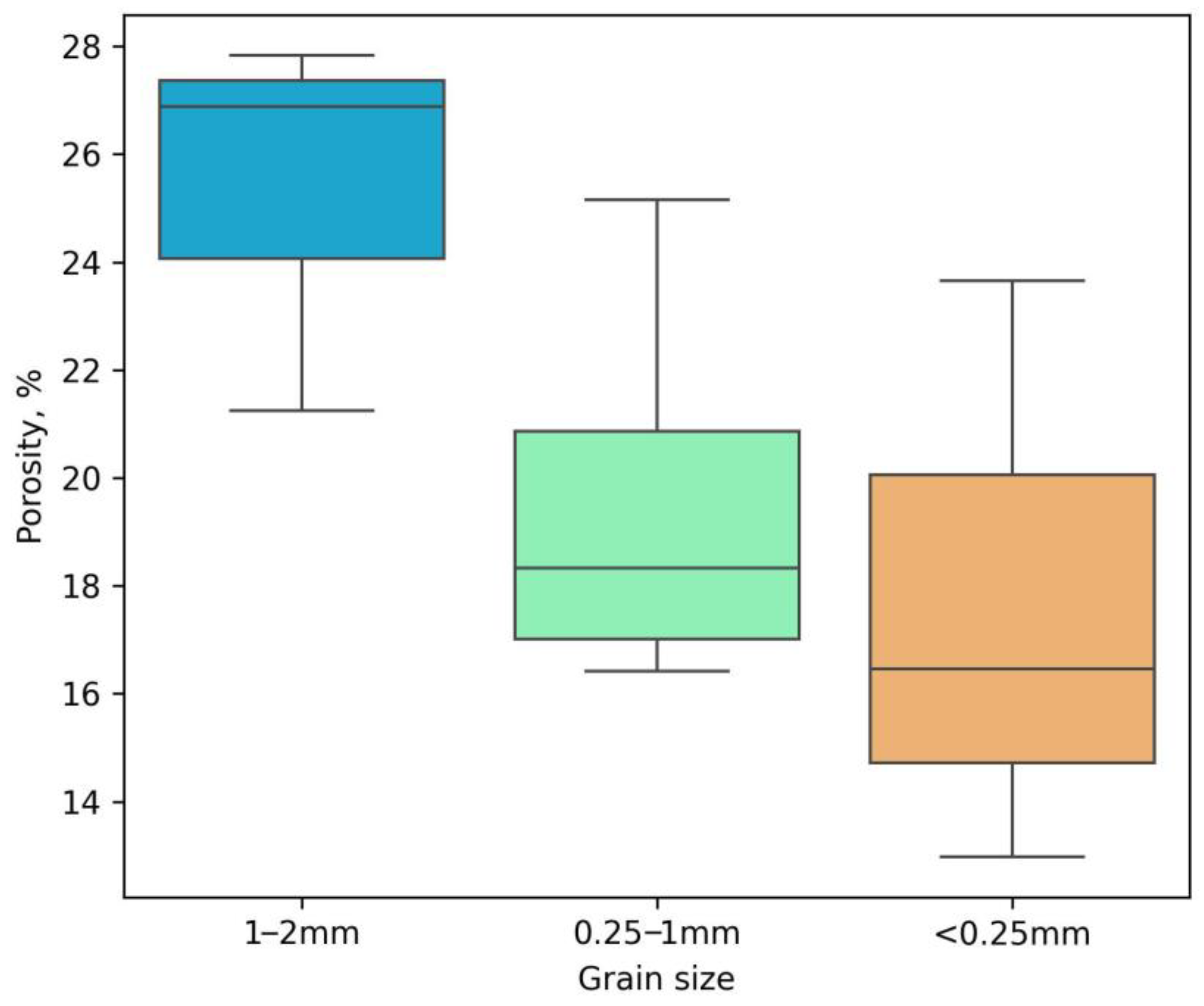
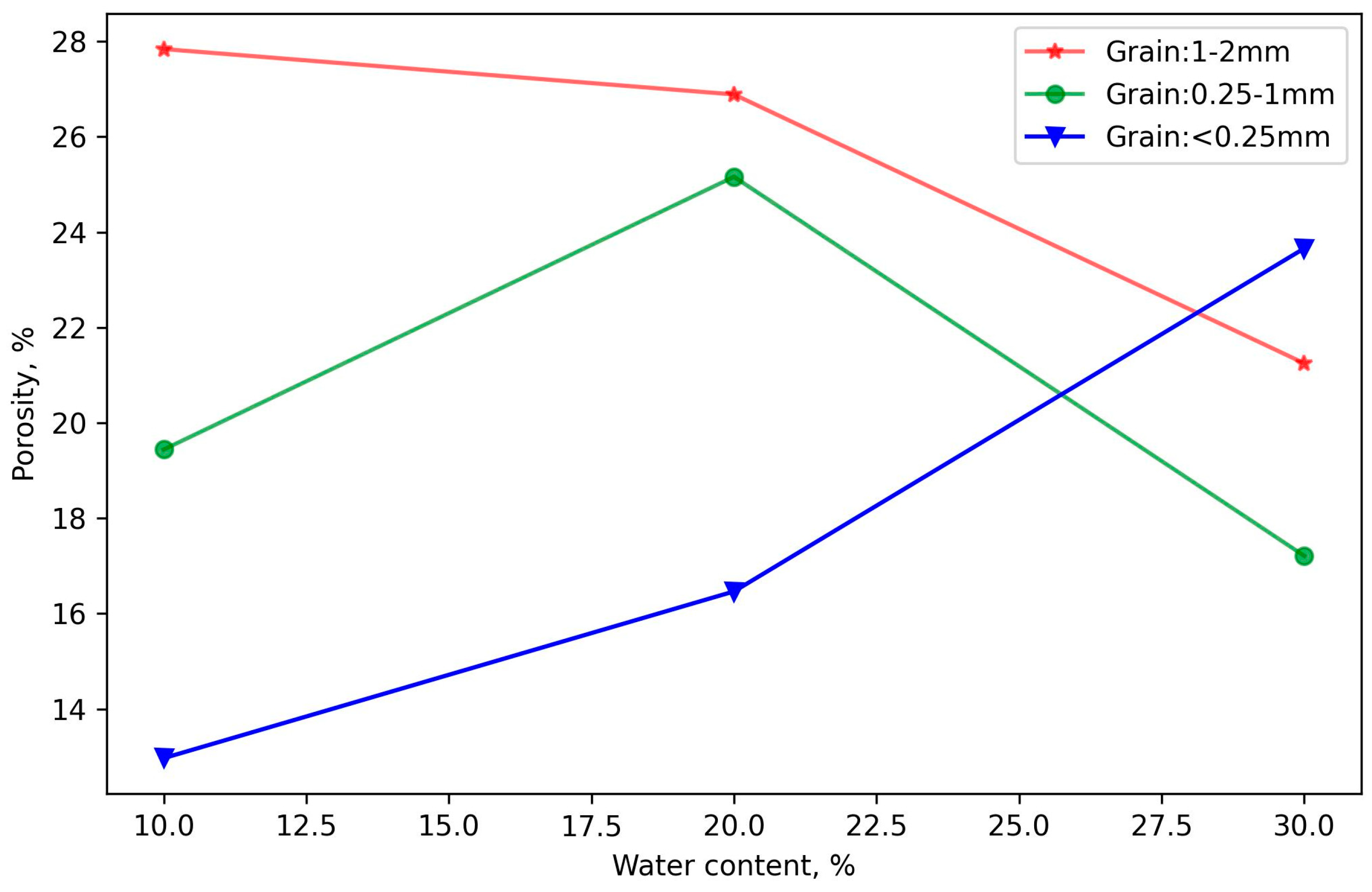
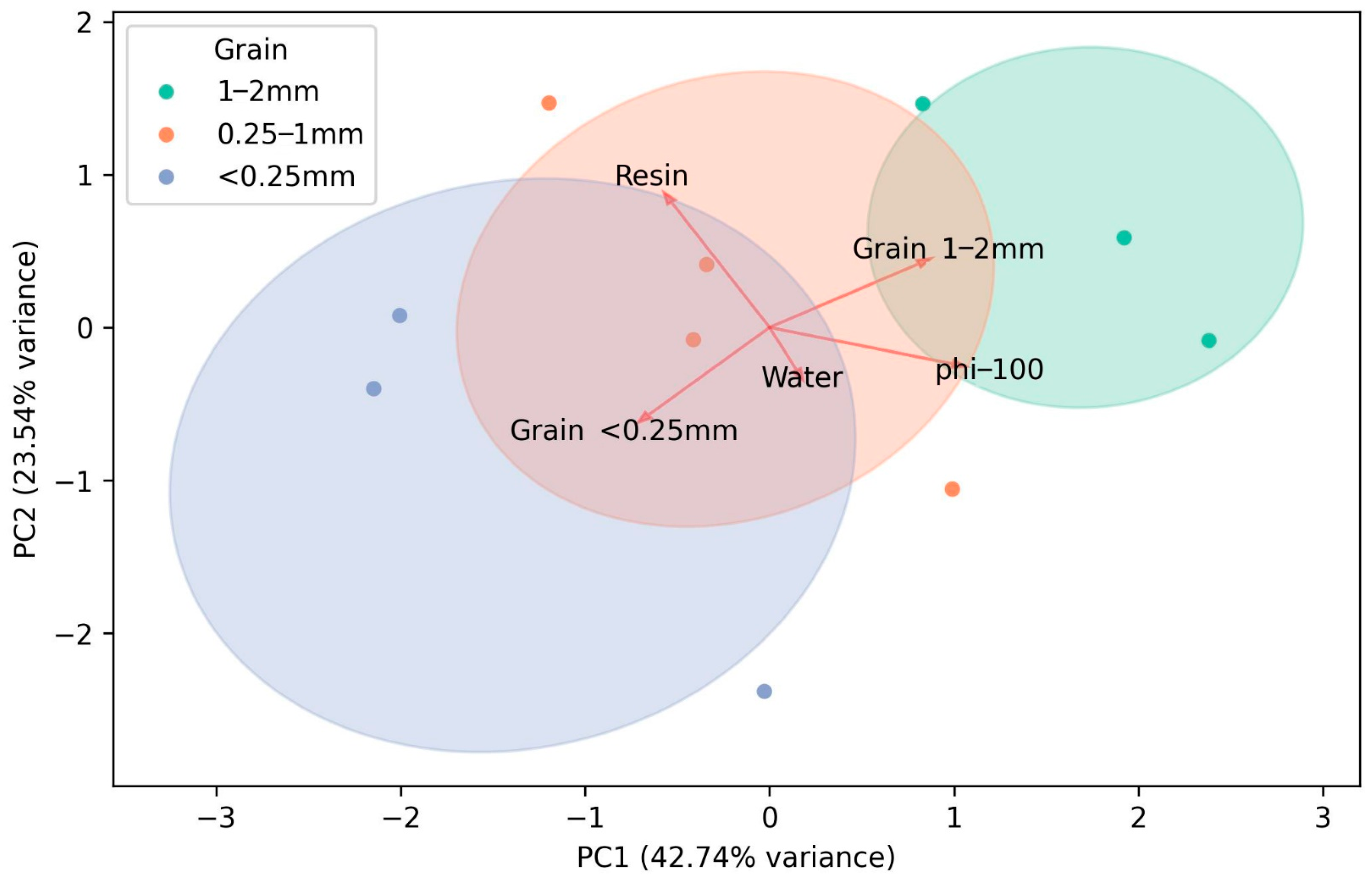
3.1. Helium Porosity of Synthetic Coal Plugs and Its Influencing Factors

To investigate the effects of three particle sizes, three epoxy resin dosages, and three moisture contents on the porosity of synthetic coal plugs, an orthogonal design method was employed. This approach optimized the original 27 experiments involving three factors at three levels each to just 10 experiments, thereby simplifying the number of experiments and effectively reducing the experimental costs (Table 1).
Statistical tests were conducted using Statistical Product and Service Solutions(SPSS), version 27 considering three factors at three levels each. The standard deviations of porosity measurements for synthetic coal plugs prepared with particle sizes of <0.25 mm, 0.25–1 mm, and 1–2 mm were 0.0545, 0.0395, and 0.0356, respectively. For resin content levels of 9 g, 15 g, and 21 g, the corresponding standard deviations were 0.0212, 0.0583, and 0.0278. Furthermore, an analysis of variance (ANOVA) was performed to assess the significance of each factor’s impact on porosity. At a 90% confidence level, the p-values for particle size, resin content, and moisture content were 0.063, 0.060, and 0.365, respectively. The corresponding F-values were 7.990, 8.350, and 1.437. These results indicate that both particle size and resin content have a statistically significant influence on porosity at the 90% confidence level, while moisture content does not appear to have a significant effect within the tested range.
(1) The porosity of synthetic plugs made from coal particles exhibits a positive correlation with particle size, where larger particles result in higher porosity.
Figure 8 presents box plots of the porosity of synthetic plugs prepared from coal particles in three size ranges: 1–2 mm (large), 0.25–1 mm (medium), and <0.25 mm (small). Both the mean and median values show that synthetic plugs made from large particles have higher porosity than those made from medium particles, which in turn have higher porosity than those made from small particles. The analysis suggests that when large particles come into contact with the surrounding stable large particles, they easily form a stable structure, with repulsive forces exceeding gravitational forces. Consequently, after pre-compaction, the synthetic plugs retain higher porosity. In contrast, under the influence of pre-compaction loads, small particles exhibit interlocking and rotation, with gravitational forces dominating repulsive forces and capillary forces playing a significant role. This leads to a more compact arrangement of particles, resulting in lower porosity in synthetic plugs made from small particles.
(2) Moisture content negatively correlates with porosity in large-grained and positively in small-grained synthetic plugs.
The findings suggest that moisture affects porosity in complex and particle-size-dependent ways. When water is added before the binder, especially in briquettes composed of particles smaller than 0.25 mm, a thin water film forms on the particle surfaces due to preferential distribution. This water film is beneficial for achieving higher porosity, as it prevents close packing and direct contact between coal particles, thereby maintaining a more open internal structure. As a result, even with small particles (which typically compact tightly), we observed unexpectedly high porosity values, reaching up to 24% (Figure 9).
However, for larger particles (1–2 mm), moisture primarily acts as a lubricant during the briquetting process. This lubrication promotes compaction, which in turn reduces porosity, an outcome that is not desirable in our context. Excessive moisture intensifies this effect, filling interstitial spaces and leading to tighter packing and lower overall porosity.
In the case of medium-sized particles (0.25–1 mm), the effect of moisture is intermediate. Initially, the formation of water films helps increase porosity, but beyond a certain moisture threshold, the lubricating effect becomes dominant, ultimately reducing porosity.
In summary, while the presence of moisture can either increase or decrease porosity depending on its interaction with particle size and distribution, our results show that promoting the formation of water films, rather than excessive lubrication, is more favorable for achieving higher porosity in coal briquettes.
(3) The amount of resin used exhibits a negative correlation with the porosity of synthetic plugs.
Figure 10 illustrates that increasing the amount of epoxy resin reduces the porosity of synthetic plugs made from large and medium-sized particles. However, an outlier is observed for small-grained synthetic plugs when using 15 g of epoxy resin, possibly due to uneven compaction or differences in drainage between the top and bottom ends. Notably, using too little epoxy resin can lead to cracking of the synthetic plugs during demolding, resulting in sample preparation failure. Therefore, incorporating 9–15 g of resin per 150 g of coal powder has been identified as an optimal range for fabricating synthetic coal plugs, providing practical guidance for researchers aiming to produce porosity-enhanced briquettes with improved structural integrity and reproducibility.
Through principal component analysis (PCA) of the three factors influencing the porosity of synthetic plugs, namely particle size, resin dosage, and moisture content, it was found that resin dosage is the most significant factor affecting porosity. Specifically, the higher the amount of epoxy resin used during plug preparation, the lower the resulting porosity of the synthetic plugs. Particle size also has a substantial impact on porosity, with large particles contributing positively and small particles having a negative effect. Moisture content has a relatively minor influence on porosity (Figure 11).
When conducting regression analysis to assess the impact of various factors on the porosity of synthetic plugs, the amount of epoxy resin used remains the most significant factor influencing porosity, with a correlation coefficient of −0.61 for the porosity of synthetic plugs. If the three particle sizes are considered collectively, their impact on porosity is similar to that of moisture content (Figure 12).

3.2. Characterization of Pore Structure of Synthetic Coal Plugs

Traditional laboratory analysis of coal rocks heavily relies on the core samples of raw coal, but the permeability of raw coal is extremely low, which significantly differs from the high-permeability zones created after large-scale volume fracturing. Therefore, it is necessary to prepare rock samples with high porosity and permeability to reconstruct the high-permeability flow channels between the coal matrix, micro-pores, and wellbore [2]. In this study, three different sizes of coal powder particles were used to create synthetic plugs with varying porosity and permeability conditions, aiming to physically simulate the enhanced properties of coal rocks after large-scale volume fracturing.
In recent years, techniques for characterizing microscopic pore features have become increasingly sophisticated, including both direct and indirect testing methods, as well as qualitative, semi-quantitative, and quantitative characterization methods [35]. To test and describe the porosity and pore structure of synthetic plugs, gas displacement, high-pressure mercury injection, and micro-CT methods were employed. These methods provided detailed information on the porosity, pore morphology, types, cementation styles, pore throat sizes, and connectivity of synthetic plugs, laying a scientific foundation for studying the seepage and production rules of deep coal seam gas.
To clarify the differences and similarities between raw coal and synthetic plugs in terms of porosity, pore structure, and permeability properties, coal rock samples were collected from the Sisan Tree Coal Mine in the Zhun South Coalfield, Xinjiang. This coal layer belongs to the Middle Jurassic Xishan Kiln Formation brown coal, with a macroscopic coal type of bright to semi-bright coal and a coal body structure of fragmented structure. Following the preparation method proposed in this chapter, most of the samples were made into ⌀50 × 100 mm synthetic plugs, except for a small portion of raw coal samples retained for comparison. Samples intended for mercury injection and micro-CT scanning were further cut and polished into 10 mm cubic blocks.

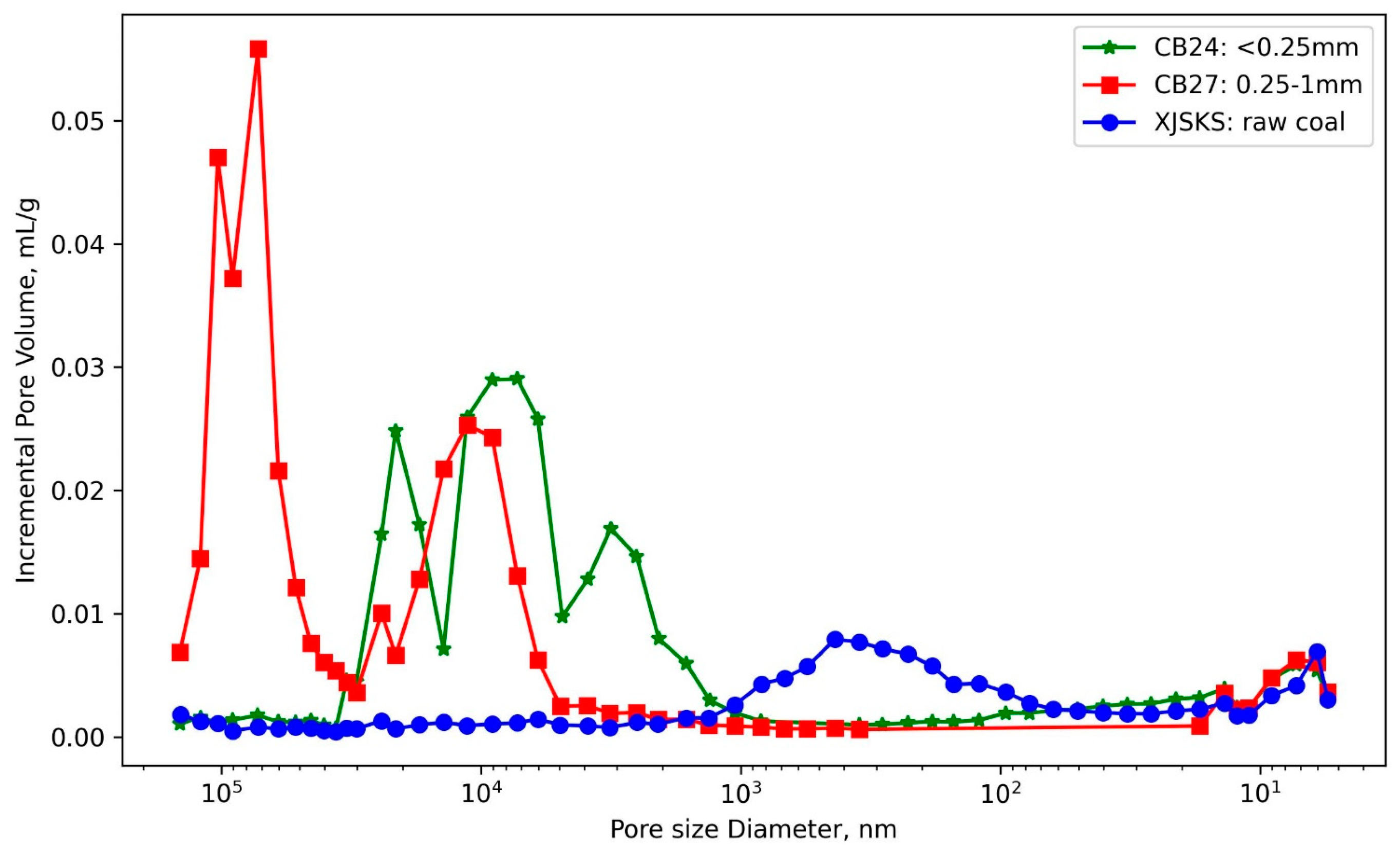
3.2.1. Mercury Intrusion Porosimetry (MIP) for Characterizing the Pore Structure of Synthetic Plugs

This study analyzed the mercury intrusion porosimetry (MIP) results for three samples (Figure 13 and Table 2). In terms of pore size, the findings indicate that raw coal has the smallest pores, followed by the small-grained synthetic plugs, while the medium-grained synthetic plugs exhibit larger pore sizes. The raw coal, which is lignite collected from Xinjiang, has pore diameters primarily distributed at 400 nm and 6 nm. According to the commonly used Hodort pore classification scheme, macropores and micropores dominate in the raw coal (Table 3). In contrast, the pores in the synthetic plugs are classified as macropores. The pore size distribution of the medium-grained synthetic plugs is broader than that of the small-grained synthetic plugs. The small-grained synthetic plugs have pore diameters ranging from 2000 to 20,000 nm (3 μm to 20 μm), while the medium-grained synthetic plugs have pore diameters not only within this range but also include a significant number of pores with diameters between 60,000 and 500,000 nm (60 μm to 500 μm).
Based on volume estimates, the median pore diameters of the raw coal, small-grained synthetic plugs, and medium-grained synthetic plugs are 287.8 nm, 7625.1 nm (7.6 μm), and 52,315.2 nm (52.3 μm), respectively.
Based on MIP measurements, raw coal exhibits the lowest porosity and permeability, followed by small-grained synthetic plugs, while the medium-grained synthetic plugs show the highest porosity and permeability among the three categories. The porosities are 14.5186%, 28.5585%, and 32.1925%, respectively. The porosity of the small-grained synthetic plugs is approximately 1.97 times that of the raw coal, while the porosity of the medium-grained synthetic plugs is about 2.22 times that of the raw coal. The estimated permeabilities are 42.3468 mD, 172.4476 mD, and 4778.1020 mD, respectively. The permeability of the small-grained synthetic plugs is about 4.07 times that of the raw coal, and the permeability of the medium-grained synthetic plugs is approximately 112.83 times that of the raw coal.
Furthermore, the tortuosity of the pores in the three coal cores follows the following order: raw coal > small-grained synthetic plugs (<0.25 mm) > medium-grained synthetic plugs (0.25–1 mm). The tortuosity values for the three are 12.83, 6.57, and 4.26, respectively. Tortuosity is defined as the ratio of the actual flow path of fluid in a rock to its visual length, serving as a crucial parameter for characterizing the microscopic pore characteristics of porous media. It is essential for simulating fluid flow and transport in porous media [24,36]. Therefore, the permeability of a fluid in medium-grained synthetic plugs exceeds that in small-grained synthetic plugs and is also greater than that in raw coal, consistent with the previous permeability estimates.
Table 3. Coal rock pore classification scheme with pore diameter in nm [32].
Hodot [37]Dubinin (1966) [38]IUPAC (1985) [39,40]Gan (1972) [41]Qin (1995) [21]
<10, Micropore<2, Micropore<2, Micropore0.4~1.2, Micropore<15, Micropore
10~100, Transition pore2~20, Transition pore2~50, Transition pore1.2~30, Transition pore15~50 Transition pore
100~1000, Mesopore50~400, Mesopore
>1000, Macropore>20, Macropore>50, Macropore30–2960, Macropore>400, Macropore

3.2.2. Micro-CT-Based Description of the Pore Structure of Synthetic Plugs

Micro-CT was employed to elucidate the differences in pore types, sizes, and contact types between raw coal and synthetic plugs. The CT scanning process involved precise control over X-ray excitation intensity, resulting in multiple two-dimensional projection images with varying degrees of attenuation after penetrating the samples. These images were then reconstructed using algorithms to create a three-dimensional microscopic pore structure and characterize spatial connectivity [32,34]. Notably, CT scans used for reservoir rock analysis, including micro-CT and nano-CT, offer higher precision compared to medical CT scans. Given that the pores in synthetic plugs are predominantly macropores, as determined by mercury intrusion porosimetry, micro-CT is particularly well suited for characterizing the microscopic structure of such reservoirs.
This micro-CT study was conducted at the Key Laboratory of Coalbed Methane and Accumulation Process, China University of Mining and Technology. A GE Phoenix V|tome|x s industrial CT system capable of achieving a spatial resolution of ≤0.6 μm and a sample overall imaging resolution of ≤12.5 μm for three-dimensional imaging was utilized. This enabled the detailed analysis and characterization of both two-dimensional and three-dimensional structures within the samples, facilitating the construction of a three-dimensional model of the internal microstructure. The samples consisted of five 10 mm cubic blocks: four synthetic plugs (CB10, CB24, CB27, and CB28) and one raw coal sample (XJSKS05-01). Among the synthetic plugs, CB10, CB24, and CB27 had iodine added during their preparation, while CB28 did not include iodine (Figure 14).
After collecting digital images, the Avizo software (version 2022.2) was utilized for image post-processing and pore structure reconstruction. The digital image resolution obtained from this scan was between 7 and 9 μm. Typically, CT scans provide grayscale information about the internal structure of rocks, where darker regions correspond to low-density pore spaces and lighter regions represent high-density rock frameworks. Grayish-white areas indicate relatively low-density rock frameworks, as observed in Figure 14d for raw coal. This method effectively identifies raw coal but struggles to differentiate between cemented materials and pores in synthetic plugs because both resin and pores appear black in the images, leading to an overestimation of porosity in synthetic plugs (Table 4). To address this issue, this study introduced dispersed iodine into the resin mixture to enhance the brightness of cemented materials in digital images, facilitating the accurate identification of cement types and reducing the likelihood of misjudging cement as pores, thereby improving the accuracy of porosity identification (Figure 15).
Moreover, the high-brightness cement between particles in digital images physically simulates the interparticle bonds that transmit overburden pressure. Large-scale volume fracturing removes some cement in the deep coal reservoir near the wellbore, causing gas and water within the pores to temporarily support overburden pressure, resulting in excess pore pressure and post-fracturing self-production [42]. The introduction of iodine aids in enhancing the understanding of the gas production mechanism in deep coal “artificial reservoirs”.
The selected representative element volume (REV) was trimmed in size; then, median filtering was applied to denoise the images. The watershed algorithm was used to complete the interactive threshold segmentation, thereby distinguishing the rock framework from pores (Figure 16). From a qualitative perspective, Figure 16 reveals that large-grained synthetic plugs exhibit the highest porosity, followed by medium-grained and small-grained synthetic plugs, with raw coal having the lowest porosity. Furthermore, the large pores within synthetic plugs are unevenly distributed, whereas the natural pores in raw coal are closely related to original sedimentation and coalification cleavage, displaying a regular oriented arrangement.
For digital rock images, zero represents pores, while one indicates the rock framework. By searching for the number of zeros and ones in the pixel matrix in three-dimensional space, the porosity can be calculated using the following formula:
ϕ = N P N P + N SK
Through binary image processing, the digital volume porosity of the five samples—CB10, CB24, CB27, CB28, and XJSKS05-01—was calculated as 31.00%, 16.32%, 25.51%, 38.45%, and 8.62%, respectively. The CB28 sample, which did not have iodine added, resulted in the cement being misclassified as pores, leading to an overestimation of porosity. The porosity of the other samples followed the following trend: large-grained synthetic plugs > medium-grained synthetic plugs > small-grained synthetic plugs > raw coal (Figure 16). By comparing these values with those obtained from mercury intrusion porosimetry (Table 4), it was found that the porosity values from CT scans were slightly lower, but the relative size order was consistent with the results from mercury intrusion porosimetry.

4. Conclusions

To physically simulate the stimulated state of intensely hydraulically fractured coal seams for deep CBM extraction, a novel approach was developed for manufacturing synthetic coal plugs. These plugs exhibit enhanced porosity and permeability with widely distributed pores, as confirmed by helium porosimeter, mercury intrusion porosimetry (MIP), and micro-CT analysis. The key findings are summarized as follows:
(1) A systematic procedure for creating synthetic coal plugs was established, detailing material preparation, the required equipment, and step-by-step fabrication. The process is based on a foundational curing system composed of phenolic epoxy resin F51 and polyamide curing agent 650. Notably, the method incorporates a tetrahydrofuran (THF)-mediated iodine dissolution system that combines an iodine solution and elemental iodine to cement wet coal powders of varying particle sizes.
(2) To ensure high-quality synthetic coal plugs, an orthogonal method was employed to evaluate the effects of three particle sizes, three epoxy resin dosages, and three moisture contents on porosity. The results indicate that the amount of resin is the primary factor impacting porosity: higher resin content leads to reduced porosity, whereas insufficient resin increases the likelihood of fabrication failures. Therefore, an optimal resin content of 6–10% by weight is recommended, corresponding to 9–15 g of resin per 150 g of coal powder for a single plug with dimensions of ⌀50 mm× 100 mm.
(3) Comparative MIP analysis showed a substantial improvement in porosity over raw coal. Small-grained synthetic plugs reached 28.56% porosity, which was about 1.97 times higher than raw coal (14.52%), while medium-grained plugs achieved 32.19%, which was approximately 2.22 times higher than raw coal. These results underscore the synthetic plugs’ suitability for simulating pore-scale processes in deep CBM reservoirs.
(4) MIP revealed a broader pore size distribution in synthetic plugs compared to natural lignite. While raw coal exhibited dominant pore sizes at approximately 6 nm and 400 nm, synthetic plugs featured significantly larger pores. Small-grained plugs ranged between 3 and 20 μm, while medium-grained plugs extended from 3 μm up to 500 μm, incorporating numerous macropores relevant to deep reservoir conditions.
(5) Micro-CT imaging revealed that large-grained synthetic plugs have the highest porosity, followed by medium- and small-grained plugs, with raw coal showing the lowest porosity. Iodine accumulation around coal particles highlighted inter-particle boundaries, improving the visualization of connected pore networks. This indicates that iodine enhances the accuracy of effective porosity estimation compared to conventional 3D reconstruction methods.

Author Contributions

Conceptualization: C.L. (Changqing Liu) and Z.Y.; methodology: C.L. (Changqing Liu); formal analysis and investigation: C.L. (Changqing Liu), Y.L., J.G. and Y.W.; writing—original draft preparation: C.L. (Changqing Liu); writing—review and editing: C.L. (Changqing Liu); supervision: Z.Y., H.C., G.Z., C.L. (Cunlei Li), B.L., S.F. and J.W. All authors have read and agreed to the published version of the manuscript.

Funding

This work is jointly supported by the National Natural Science Foundation of China (Grant No. 42272195, No. 42130802). This study is also supported by the Key Applied Science and Technology Project of PetroChina (No. 2023ZZ18) and the Major Science and Technology Project of Changqing Oilfield (No. 2023DZZ01).

Data Availability Statement

The original contributions presented in this study are included in the article. Further inquiries can be directed to the corresponding author.

Conflicts of Interest

Author Heqing Chen was employed by the Xinjiang Oilfield Company. Author Guoxiao Zhou was employed by the PetroChina Changqing Oilfield Company. The remaining authors declare that the research was conducted in the absence of any commercial or financial relationships that could be construed as a potential conflict of interest.

References

  1. Xu, F.; Yan, X.; Li, S.; Xiong, X.; Wang, Y.; Zhang, L.; Liu, C.; Han, J.; Feng, Y.; Zhen, H.; et al. Theoretical and Technological Difficulties and Countermeasures of Deep CBM Exploration and Development in the Eastern Edge of Ordos Basin. Meitiandizhi Yu Kantan/Coal Geol. Explor. 2023, 51, 115–130. (In Chinese) [Google Scholar] [CrossRef]
  2. Xu, F.; Nie, Z.; Sun, W.; Xiong, X.; Xu, B.; Zhang, L.; Shi, X.; Liu, Y.; Liu, S.; Zhao, Z.; et al. Theoretical and Technological System for Highly Efficient Development of Deep Coalbed Methane in Daning-Jixian Block. J. China Coal Soc. 2024, 49, 528–544. (In Chinese) [Google Scholar] [CrossRef]
  3. Qin, Y. Progress on Geological Research of Deep Coalbed Methane in China. ACTA Pet. Sin. 2023, 44, 1791–1811. (In Chinese) [Google Scholar]
  4. Li, S.; Qin, Y.; Tang, D.; Shen, J.; Wang, J.; Chen, S. A Comprehensive Review of Deep Coalbed Methane and Recent Developments in China. Int. J. Coal Geol. 2023, 279, 104369. [Google Scholar] [CrossRef]
  5. Fu, X.; Kang, J.; Chen, Y.; Duan, C.; Lu, J.; Zhang, B. Analysis on Terminologies Related to Coalbed Methane. J. China Univ. Min. Technol. 2025, 54, 26–33. (In Chinese) [Google Scholar]
  6. Yao, H.; Chen, Z.; He, X.; Wang, Y.; Jiang, Y. “Effective Support” Concept and Innovative Practice of Deep CBM in South Yanchuan Gas Field of the Ordos Basin. Nat. Gas Ind. 2022, 42, 97–106. (In Chinese) [Google Scholar] [CrossRef]
  7. Ye, J. China’s CBM Exploration and Production and Associated Technological Advancements: A Review and Reflections. Coal Geol. Explor. 2025, 53, 114–127. (In Chinese) [Google Scholar] [CrossRef]
  8. Li, G.; Zhang, S.; He, H.; He, X.; Zhao, Z.; Niu, X.; Xiong, X.; Zhao, Q.; Guo, X.; Hou, Y.; et al. Coal-Rock Gas:Concept, Connotation and Classification Criteria. Pet. Explor. Dev. 2024, 51, 783–795. (In Chinese) [Google Scholar] [CrossRef]
  9. Zou, C.; Ding, Y.; Lu, Y.; Liu, X.; Chen, J.; Wang, X.; Yang, Z.; Cai, B.; Yang, Z.; He, C.; et al. Concept, Technology and Practice of “Man-Made Reservoirs”Development. Pet. Explor. Dev. 2017, 44, 144–154. (In Chinese) [Google Scholar] [CrossRef]
  10. Warpinski, N.R.; Lorenz, J.C.; Branagan, P.T.; Myal, F.R.; Gall, B.L. Examination of a Cored Hydraulic Fracture in a Deep Gas Well. SPE Prod. Facil. 1993, 8, 150–158. [Google Scholar] [CrossRef]
  11. Cornet, F.H.; Valette, B. In Situ Stress Determination from Hydraulic Injection Test Data. J. Geophys. Res. Solid Earth 1984, 89, 11527–11537. [Google Scholar] [CrossRef]
  12. Warpinski, N.R.; Laboratories, S.N.; Teufel, L.W.; Laboratories, S.N. Influence of Geologic Discontinuities on Hydraulic Fracture Propagation. J. Pet. Technol. 1987, 39, 209–220. [Google Scholar] [CrossRef]
  13. Raterman, K.T.; Farrell, H.E.; Mora, O.S.; Janssen, A.L.; Gomez, G.A.; Busetti, S.; McEwen, J.; Friehauf, K.; Rutherford, J.; Reid, R.; et al. Sampling a Stimulated Rock Volume: An Eagle Ford Example. SPE Reserv. Eval. Eng. 2018, 21, 927–941. [Google Scholar] [CrossRef]
  14. Zhang, K.; Wang, S.; Wang, L.; Cheng, Y.; Li, W.; Han, X.; Liu, C.; Su, H. 3D Visualization of Tectonic Coal Microstructure and Quantitative Characterization on Topological Connectivity of Pore-Fracture Networks by Micro-CT. J. Pet. Sci. Eng. 2022, 208, 109675. [Google Scholar] [CrossRef]
  15. Hu, X.; Liang, W.; Hou, S.; Zhu, X.; Huang, W. Experimental Study of Effect of Temperature and Stress on Permeability Characteristics of Raw Coal and Shaped Coal. Chinese J. Rock Mech. Eng. 2012, 31, 1222–1229. (In Chinese) [Google Scholar]
  16. Wu, X.; Liu, C. Analysis of Moulded Coal Porosity Base on Surface Characteristics. Procedia Eng. 2011, 26, 1058–1064. [Google Scholar] [CrossRef]
  17. Tulepov, M.I.; Sassykova, L.R.; Kerimkulova, A.R.; Tureshova, G.O.; Tolep, D.M.; Zhapekova, A.O.; Spanova, G.A.; Abdrakova, F.Y.; Mansurov, Z.A. Preparation of Coal Briquettes and Determination of Their Physical and Chemical Properties. Orient. J. Chem. 2019, 35, 180–185. [Google Scholar] [CrossRef]
  18. Wu, L. Research on the Influences of Particle Gradation and Added Moisture on the Compactibility of Jincheng Anthracite. China Coal 2023, 49, 117–121. (In Chinese) [Google Scholar]
  19. Yan, M.; Deng, J.; Tian, D.; Yu, B.; Xiao, Q.; Chen, Z. Research on Uniaxial Mechanical Properties of Synthetic Sandstones Cemented with Epoxy Resin Adhesives. Pet. Sci. Bull. 2023, 8, 600–613. (In Chinese) [Google Scholar] [CrossRef]
  20. Xu, H.; Xiong, Y.; Wang, Y.; Zhou, W.; Wang, L.; Jiang, Q. Preparation and Evaluation on Artificial Core of Extra High Permeability Unconsolidated Sandstone. Oil Drill. Prod. Technol. 2017, 39, 477–483. (In Chinese) [Google Scholar] [CrossRef]
  21. Qin, Y.; Xu, Z.; Zhang, J. Natural Classification of the High-Rank Coal Pore Structure and Its Application. J. China Coal Soc. 1995, 20, 266–271. (In Chinese) [Google Scholar]
  22. Gao, J.; Li, Z.; Tao, X.; Li, X.; Zhu, K. A Comprehensive Study of Multiscale Pore Structural Characteristics in Deep-Buried Coals of Different Ranks. Sci. Rep. 2025, 15, 8299. [Google Scholar] [CrossRef] [PubMed]
  23. Lu, F.; Liu, C.; Zhang, X.; Jia, B.; Wang, Y.; Liu, S.; Tang, Y.; Liu, J.; Lin, P. Study on Full-Scale Pores Characterization and Heterogeneity of Coal Based on Low-Temperature Nitrogen Adsorption and Low-Field Nuclear Magnetic Resonance Experiments. Sci. Rep. 2024, 14, 16910. [Google Scholar] [CrossRef] [PubMed]
  24. Zhu, Y.-M.; Yue, W.-Z.; Zhang, X.; Wang, Z.; Lu, M.-Y. Advances on the Calculation Methods of Tortuosity in Porous Media. Prog. Geophys. 2023, 38, 1293–1304. (In Chinese) [Google Scholar]
  25. Zdravkov, B.D.; Čermák, J.J.; Šefara, M.; Janků, J. Pore Classification in the Characterization of Porous Materials: A Perspective. Cent. Eur. J. Chem. 2007, 5, 385–395. [Google Scholar] [CrossRef]
  26. Jiang, C.; Wei, W.; Liu, X.; Wu, J. Study on Seepage Characteristics and Visualization of Coal and Rock under Coupled Stress-Strain-Seepage Conditions. Min. Saf. Environ. Prot. 2022, 49, 59–63. (In Chinese) [Google Scholar]
  27. Li, Z.; Ren, T.; Li, X.; Qiao, M.; Yang, X.; Tan, L.; Nie, B. Multi-Scale Pore Fractal Characteristics of Differently Ranked Coal and Its Impact on Gas Adsorption. Int. J. Min. Sci. Technol. 2023, 33, 389–401. [Google Scholar] [CrossRef]
  28. Bouxsein, M.L.; Boyd, S.K.; Christiansen, B.A.; Guldberg, R.E.; Jepsen, K.J.; Müller, R. Guidelines for Assessment of Bone Microstructure in Rodents Using Micro-Computed Tomography. J. Bone Miner. Res. 2010, 25, 1468–1486. [Google Scholar] [CrossRef]
  29. GB/T 29172-2012; Practices for Core Analysis. Standardization Administration of China: Beijing, China, 2012. (In Chinese)
  30. GB/T 34533-2017; Measurement of Helium Porosity and Pulse Decay Permeability of Shale. Standardization Administration of China: Beijing, China, 2017. (In Chinese)
  31. Washburn, E.W. The Dynamics of Capillary Flow. Phys. Rev. 1921, 17, 273–283. [Google Scholar] [CrossRef]
  32. Hu, B.; Cheng, Y.; Pan, Z. Classification Methods of Pore Structures in Coal: A Review and New Insight. Gas Sci. Eng. 2023, 110, 204876. [Google Scholar] [CrossRef]
  33. GB/T 21650.1-2008/ISO 15901-1:2005; Pore Size Distribution and Porosity of Solid Materials by Mercury Porosimetry and Gas Adsorption—Part 1: Mercury Porosimetry. General Administration of Quality Supervision, Inspection and Quarantine of China & China National Standardization Administration: Beijing, China, 2008.
  34. Wang, Y.; Rahman, S.S. Numerical Modelling of Reservoir at Pore Scale: A Comprehensive Review. J. Comput. Phys. 2023, 472, 111680. [Google Scholar] [CrossRef]
  35. Fu, X.; Qi, Q.; Cheng, M.; Zhang, B. Review of Research on Test, Simulation and Prediction of Coal Reservoir Permeability. J. China Coal Soc. 2022, 47, 2369–2385. (In Chinese) [Google Scholar]
  36. Carman, P.C. Flow of Gases Through Porous Media, 1st ed.; Academic Press: London, UK, 1956. [Google Scholar]
  37. Hodot, B.B.; Song, S.; Wang, Y. Coal and Gas Outburst, 1st ed.; China Building Industry Press: Beijing, China, 1966. (In Chinese) [Google Scholar]
  38. Dubinin, M.M. Modern State of the Theory of Gas and Vapour Adsorption by Microporous Adsorbents. Pure Appl. Chem. 1965, 10, 309–322. [Google Scholar] [CrossRef]
  39. Sing, K.S.W.; Everett, D.H.; Haul, R.A.W.; Moscou, L.; Pierotti, R.A.; Rouquerol, J.; Siemieniewska, T. Reporting Physisorption Data for Gas/Solid Systems with Special Reference to the Determination of Surface Area and Porosity. Pure Appl. Chem. 1985, 57, 603–619. [Google Scholar] [CrossRef]
  40. Thommes, M.; Kaneko, K.; Neimark, A.V.; Olivier, J.P.; Rodriguez-Reinoso, F.; Rouquerol, J.; Sing, K.S.W. Physisorption of Gases, with Special Reference to the Evaluation of Surface Area and Pore Size Distribution (IUPAC Technical Report). Pure Appl. Chem. 2015, 87, 1051–1069. [Google Scholar] [CrossRef]
  41. Gan, H.; Nandi, S.P.; Walker, P.L. Nature of the Porosity in American Coals. Fuel 1972, 51, 272–277. [Google Scholar] [CrossRef]
  42. Liu, C.; Yang, Z.; Qin, Y.; Yan, X.; Wang, Y.; Wang, Z. Excess Pore Pressure Behavior and Evolution in Deep Coalbed Methane Reservoirs. Int. J. Min. Sci. Technol. 2024, 34, 763–781. [Google Scholar] [CrossRef]
Figure 1. Preparation procedure of manufacturing synthetic coal plugs: (a) Flow chart; (b) Equipment and materials.
Energies 18 02407 g001
Figure 2. Raw coal from the Zhongfu Coal Mine in Xinjiang was crushed and screened into three particle sizes of pulverized coal: (a,b) represent large granular pulverized coal with a particle size of 1–2 mm and synthetic coal plug, respectively; (c,d) represent medium-grained pulverized coal with a particle size of 0.25–1 mm and synthetic coal plugs, respectively; (e,f) represent small-grained pulverized coal with a particle size of <0.25 mm and synthetic coal plugs, respectively.
Energies 18 02407 g002aEnergies 18 02407 g002b
Figure 3. Diagram of pre-loading and molding for synthetic coal plugs.
Energies 18 02407 g003
Figure 4. Finished synthetic coal plugs: (a) side view of the synthetic coal plugs corresponding to the three particle sizes from left to right: 1–2 mm, 0.25–1 mm, and <0.25 mm; (b) top view of the synthetic coal plug corresponding to the three particle sizes from left to right: 1–2 mm, 0.25–1 mm, and <0.25 mm.
Energies 18 02407 g004aEnergies 18 02407 g004b
Figure 5. Flow chart of helium porosimetry.
Energies 18 02407 g005
Figure 6. AutoPore IV 9500.
Energies 18 02407 g006
Figure 7. Schematic diagram of the CT scanning principle [28].
Energies 18 02407 g007
Figure 8. Box plot of porosity for synthetic coal plugs from different sizes of particles.
Energies 18 02407 g008
Figure 9. Relationship between water content and porosity under different particle size conditions.
Energies 18 02407 g009
Figure 10. Relationship between resin content and porosity under different particle size conditions.
Energies 18 02407 g010
Figure 11. Principal component analysis (PCA) of porosity for synthetic coal plug samples.
Energies 18 02407 g011
Figure 12. Regression analysis of factors influencing porosity and heat map display for synthetic coal plugs.
Energies 18 02407 g012
Figure 13. Comparison of the mercury injection curve and pore structure between synthetic coal plugs and raw coal.
Energies 18 02407 g013
Figure 14. Five synthetic coal cube samples for micro-CT scanning: (a) CB24 sampled from small-grained synthetic plugs with iodine (grain diameter <0.25 mm); (b) CB27 sampled from medium-grained synthetic plugs with iodine (grain diameter: 0.25–1 mm); (c) CB10 sampled from large-grained synthetic plugs with iodine (grain diameter: 1–2 mm); (d) XJSKS05-01 sampled from lignite in Xinjiang, China; (e) CB28 sampled from medium-grained synthetic plugs without iodine (grain diameter: 0.25–1 mm).
Energies 18 02407 g014
Figure 15. Role of iodine in indicating the location of resin cements in the synthetic coal plugs of medium particles: (a) CB27 with iodine; (b) CB28 without iodine.
Energies 18 02407 g015
Figure 16. CT scanning and pore structure reconstruction of four different cores: (a) CB24 sampled from small-grained synthetic plugs with iodine (grain diameter <0.25 mm); (b) CB27 sampled from medium-grained synthetic plugs with iodine (grain diameter: 0.25–1 mm); (c) CB10 sampled from large-grained synthetic plugs with iodine (grain diameter: 1–2 mm); (d) XJSKS05-01 sampled from lignite in Xinjiang, China.
Energies 18 02407 g016
Table 1. Properties of synthetic coal plugs.
Sample IDParticle Size, mmF51 Resin Content, gWeight of Particles, gWater Content in Weight, %Diameter, cmHeight, cmPore Volume, cm3Helium Porosity, %
Orth011~29.00 150.00 10.00 4.98 9.33 50.66 27.84
Orth021~215.00 150.00 20.00 4.99 10.13 53.26 26.89
Orth031~221.00 150.00 30.00 4.98 9.07 37.48 21.25
Orth040.25~19.00 150.00 20.00 4.97 9.56 46.61 25.16
Orth050.25~115.00 150.00 10.00 4.98 9.18 34.79 19.44
Orth060.25~121.00 150.00 10.00 4.98 8.89 28.42 16.41
Orth07<0.259.00 150.00 30.00 4.99 9.17 42.43 23.66
Orth08<0.2515.00 150.00 10.00 5.00 9.40 23.94 12.97
Orth09<0.2521.00 150.00 20.00 5.00 9.30 30.07 16.47
Orth100.25~115.00 150.00 30.00 4.99 9.15 30.80 17.21
Table 2. Comparison of mercury injection characteristics between raw coal and synthetic coal plugs.
Grain Size/TypeTotal Pore Area, m2/gMedian Pore Diameter, nmPorosity, %Threshold Pressure, kPaEstimated Permeability, mDTortuosity
Raw coal14.26 287.80 14.52 24.13 42.35 12.83
Grain: <0.25 mm15.55 7625.10 28.56 57.78 172.45 6.57
Grain: 0.25–1 mm13.82 52315.20 32.19 12.00 4778.10 4.26
Table 4. Micron-CT 3D pore extraction and quantitative characterization.
Sample IDCT Porosity, %Label Volume, ×1019Mask Volume, ×1020Label Voxel Count, ×107Mask Voxel Count, ×107Notes
CB1031.00 8.86 2.86 12.20 39.20 synthetic coal with iodine; Grain diameter: 1–2 mm;
CB2416.32 4.39 2.69 1.60 9.80 synthetic coal with iodine; Grain diameter <0.25 mm
CB2725.51 6.41 2.51 12.50 49.10 synthetic coal with iodine; Grain diameter: 0.25–1 mm
CB2838.45 11.70 3.03 22.80 59.30 synthetic coal; porosity is overestimated due to the absence of iodine addition
XJSKS05-018.62 3.65 4.23 7.12 82.70 Lignite
Disclaimer/Publisher’s Note: The statements, opinions and data contained in all publications are solely those of the individual author(s) and contributor(s) and not of MDPI and/or the editor(s). MDPI and/or the editor(s) disclaim responsibility for any injury to people or property resulting from any ideas, methods, instructions or products referred to in the content.

