1. Introduction
With continuous progress in the energy industry, the utilization of renewable and clean energy sources, such as wind power and photovoltaic power generation, is constantly increasing. Integrated energy systems are being adopted by more and more industries due to their significant advantages in terms of the local consumption of new energy, improvements in energy efficiency, and energy cost savings. Comprehensive energy planning and optimization research on electricity, heat, and natural gas not only gives full play to the multi-energy complementary characteristics of these energy systems, improves the efficiency of energy storage and conversion, reduces isolation and blockages between different energy networks, promotes the consumption of clean energy, and ensures system safety, but also has important guiding significance for the short-term operation and medium-to-long-term planning of comprehensive energy systems. Therefore, as a platform for integrating multiple energy sources and optimizing energy allocation and utilization, the concept of the comprehensive energy system is becoming an important way to promote the efficient use of energy and build an environmentally friendly society.
The synergy of energy storage systems is becoming increasingly prominent in the construction and development of integrated energy systems. Energy storage technology not only balances the difference between energy supply and demand, improving the flexibility and reliability of the energy system, but is also the key to the efficient use and grid connection of renewable energy. In recent years, hybrid energy storage systems have attracted much attention because they can combine the advantages of different energy storage technologies, such as the fast response of battery energy storage with thermal energy storage and the large capacity and long-term energy storage characteristics of natural energy storage.
Sun, J. et al. [
1] proposed distributed energy storage resource management and coordinated control strategies based on demand-side response to improve energy storage efficiency. Zeng, S. [
2] considered the interests of multiple parties and used a multi-factor weighted solution method to obtain a collaborative solution under load demand response. Qi, C. [
3] proposed a collaborative optimization strategy for electric–thermal multi-energy storage that minimizes the economic cost of the system. Chen, C. [
4] used a collaborative control strategy that divides the peak frequency regulation interval according to the state of charge. Ma, R. et al. [
5] proposed a collaborative strategy for renewable energy systems with the maximum new energy consumption rate, with power transmission as the optimization objective. Wang, K. et al. [
6] established a multi-objective optimization model and algorithm for a combined wind–water–fire power system. Reddy, S. [
7] proposed a system-adapted day-ahead plan by minimizing the day-ahead and real-time adjustment costs. Zhu, J. [
8] developed an economic strategy with multiple timescales, turning deterministic constraints at different times into robust constraints with uncertainty added. Yao, D.L. et al. [
9] established a short-term model for a wind power grid-connected energy storage system, divided into charging and discharging energy storage systems. Ntomaris, A.V. et al. [
10] proposed a two-stage stochastic optimization model for the joint energy and reserve dispatch of conventional units and hybrid power plants in islanded power systems. Bera, S. et al. [
11] proposed a dynamic demand scheme to try to achieve low energy cost losses at the client end. However, how to design a reasonable power distribution strategy to give full play to the synergistic effect of the hybrid energy storage system remains the focus and difficulty of current research.
On the other hand, the optimization of integrated energy system planning involving electrical coupling is also a current research hotspot. As an important part of integrated energy systems, electricity–gas systems can achieve the efficient use and flexible scheduling of energy through the mutual conversion and synergy of electricity and natural gas. Wang, S. et al. [
12] established a source–load interaction model for the multi-energy complementarity of electricity and heat in order to implement a dual-carbon policy and incorporate demand response while ensuring user satisfaction. Li, T. et al. [
13] proposed an optimization model for integrated energy system planning that considers the synergy of electricity and heat storage, with the optimization goal of minimizing total annual cost. Rong, Y. et al. [
14] considered construction constraints, including unit floor area, and established an energy efficiency model including power quality. Shen, H. et al. [
15] proposed an optimization planning method for an electric–heat integrated energy system that considers the flexible configuration of thermal storage and the hydraulic and thermal properties of the heat network. Wang, Y. [
16] established an interval model for photovoltaic and solar thermal power output, taking into account the uncertainty of renewable energy output and the randomness of energy consumption by multiple loads in oil fields. Wen, G. et al. [
17] used the NSGA-II algorithm to optimize the equipment type and capacity configuration of the comprehensive energy system. Ding, Y. et al. [
18] constructed a system capacity planning model that takes into account multi-objective coordination to complete the capacity planning of motors and energy storage equipment. Jiang, T. [
19] proposed a low-carbon optimization planning method for integrated energy systems based on an uncertain affine model of DG. Zhou, C. et al. [
20] proposed an opportunity-constrained programming-based coordinated optimization scheduling strategy for the controller–worker game of IB and ICES. Wang, Y. et al. [
21] proposed a two-stage planning optimization method for the capacity and cost of an integrated energy system that considers the uncertainty of wind and solar energy in the face of problems such as the strong fluctuations and uncertainty of renewable energy in integrated energy system planning. Fan, H. et al. [
22] derived the energy capacity allocation of various regions based on the economic and carbon emission costs of a multi-regional system. Wang, Z. et al. [
23] analyzed the robust unit commitment of an electricity–gas coupled system based on system reserve capacity. However, the complexity of the electricity–gas system poses many challenges for planning and optimization, such as the coordinated control of electrical equipment, optimization strategies for energy flows, and consideration of the operating characteristics of key equipment, such as alkaline electrolyzers. Therefore, in-depth research on planning and optimization methods for integrated energy systems involving electrical coupling is of great significance for improving the overall efficiency, reliability, and economy of the energy system.
As can be seen from
Table 1 below, most of the existing research focuses on the planning and optimization of the type and capacity of energy storage equipment in comprehensive energy systems. However, there are few studies on how to achieve multi-timescale energy supply and demand balance optimization through the rational design of a hybrid energy storage mode. Therefore, it is necessary to develop a hybrid energy storage power allocation method that combines short-term and long-term perspectives, based on the characteristics of electrical, gas, and thermal energy storage, in order to provide a reasonable planning capacity for each energy storage device. Based on the above research status, this paper proposes an optimization method for planning a comprehensive energy system based on hybrid energy storage. The main contributions of this paper can be summarized as follows:
- (1)
Energy storage power distribution method based on the grey wolf method and the adaptive noise integrated empirical mode decomposition method. An innovative method is proposed to combine the grey wolf optimization algorithm with the adaptive noise integrated empirical mode decomposition method. This method combines ICEMDAN decomposition, fuzzy control, and the GWO algorithm, and comprehensively considers the frequency domain characteristics of power signals, the state of energy storage equipment, and system optimization strategies. It can effectively optimize energy storage and distribution strategies, improve the flexibility and response speed of the system, and enhance the adaptability of the power system under different loads and complex conditions.
- (2)
Alkaline electrolyzer characteristics and refined energy management strategies for electro-gas hybrid energy storage systems: The strategy maintains the SOC of the electrochemical energy storage system in the middle range and uses the scheduling method of giving priority to gas energy storage, supplemented with electrochemical energy storage to reduce the dependence on electrochemical energy storage. In addition, a variety of operation modes (such as supporting electrochemical energy storage in electrolytic cells, starting and stopping fuel cells, etc.) are introduced to extend the operation time of electrolytic cells and reduce wind power reduction, so as to improve system efficiency and reliability and optimize energy utilization and stability.
- (3)
Multi-objective planning optimization model of a hybrid energy storage-based integrated energy system: A multi-objective optimization model of an integrated energy system is constructed, combining various energy forms such as electricity, heat, and gas, and introducing hybrid energy storage technology. Multiple objectives such as economic efficiency, environmental friendliness, and reliability are considered. By optimizing the system configuration, the model is dedicated to achieving an efficient use of energy, stable supply, and green transformation, promoting sustainable development.
The remainder of this study consists of the following.
Section 2 introduces the power distribution method of the hybrid energy storage system, the energy management strategy of the electro-gas system, and the modeling of key equipment in the electrothermal system.
Section 3 details a multi-objective planning optimization model for a hybrid energy storage-based multi-timescale integrated energy system.
Section 4 analyzes a simulation study using a park in Shanxi Province, China, as an example.
Section 5 presents the conclusions.
Table 1.
Summary of comparisons between this study and previous studies.
Table 1.
Summary of comparisons between this study and previous studies.
| Literature | Energy Storage Device | Power Allocation Method | Optimization Objectives | Solving Algorithm |
|---|
| Economy | Low-
Carbon | Energy
Efficiency | Reliability |
|---|
| [1] | Distributed Energy Storage | Cooperative Response | √ | × | √ | √ | Second-order Cone
Relaxation |
| [2] | Electrochemical Energy Storage | Constraint Restriction | × | √ | √ | × | Cplex Solution |
| [3] | Lithium Iron Phosphate Battery | Zoned and Time-shifted | √ | × | √ | √ | / |
| [4] | / | Dynamic Regulation | × | √ | √ | √ | Cplex Solution |
| [5] | / | On-demand Allocation | √ | √ | √ | × | Improved Particle Swarm Optimization (IPSO) |
| [6] | Battery Energy Storage | Predictive Optimization | × | √ | × | × | Genetic Algorithm (GA) |
| [7] | / | Hierarchical Optimization | × | √ | × | √ | Cplex Solution |
| [8] | Battery Energy Storage System (BESS) | Predictive Balancing | × | √ | × | × | / |
| [9] | Pumped Storage Power Station | Stochastic Optimization | √ | √ | √ | × | Cplex Solution |
| [10] | / | Dynamic Optimization | √ | × | × | × | / |
| [11] | / | Adaptive Adjustment | √ | × | × | √ | Column Generation for Constraints |
| [12] | Gas Storage (GS) and Heat Storage (HS) | Comprehensive Optimization | √ | √ | × | × | Gurobi Solution |
| [13] | Heat Storage Tank | Coordinated Optimization | √ | √ | × | × | CPLEX Solution |
| [14] | Pipeline | Collaborative Optimization | √ | √ | √ | × | Continuous Conic
Optimization |
| [15] | Gas Storage Equipment | Comprehensive Optimization | √ | √ | × | × | Modern Interior Point Method |
| [16] | Battery Storage and Gas Pipeline Network | Collaborative Optimization | √ | × | × | √ | Deterministic Transformation Solution |
| [17] | Electrical Energy Storage and Gas Storage | Coordinated Optimization | √ | √ | × | × | Multi-Scenario Method |
| [18] | Heat Storage Tank | Collaborative Optimization | √ | × | √ | × | Normal Boundary Intersection Method (NBI) |
| [19] | Electrical Storage Equipment (ES) and Heat Storage Equipment (HS) | Collaborative Optimization | √ | √ | √ | √ | Two-Stage Solution |
| [20] | Electrical Storage Device and Gas Storage Device | Collaborative Optimization | √ | × | × | √ | Combination of Linearization and Second-Order Conic Relaxation |
| [21] | Diversified Energy Storage | Ordered Coordination | √ | × | √ | √ | / |
| [22] | Integrated Energy Storage | Balanced Coordination | √ | √ | √ | × | Step-by-Step Solution |
| [23] | Gas Storage Tank | Collaborative Balancing | √ | √ | × | √ | Branch and Bound (B&B) |
| This paper | Energy Storage Battery, Gas Storage Tank, Heat Storage Tank | Storage Power Allocation Method Based on Grey Wolf Optimizer and Adaptive Noise Integrated Empirical Mode Decomposition | √ | √ | √ | × | NSGA-II |
2. Systematic Energy Management Strategies and Equipment Modeling
In this section, a power allocation method for energy storage based on the grey wolf optimizer (GWO) and adaptive noise ensemble empirical mode decomposition (ANEEMD) is first proposed. This method decomposes the original power of the hybrid energy storage system into high-frequency power and low-frequency power, which are allocated to electrochemical energy storage and gaseous energy storage, respectively. Furthermore, based on the operating characteristics of alkaline electrolyzers, a corresponding electric–gas energy management strategy is constructed. Finally, models for the electric–gas equipment involved in this system are established.
2.1. Power Distribution Method for Hybrid Energy Storage Systems
A reasonable power allocation method can effectively enhance the energy scheduling efficiency of different energy storage devices within a hybrid energy storage system, while reducing operational losses and extending the service life of the equipment.
2.1.1. Energy Storage System Decomposition Strategy
Modern power systems place higher demands on the capacity, power, response speed, and cost of energy storage devices. A single energy storage technology cannot meet the requirements of a comprehensive energy system. A hybrid energy storage system (HESS) combines different energy storage technologies that complement each other’s energy storage characteristics, compensating for the shortcomings of single energy storage devices, improving the overall performance of the system, and improving output fluctuations in wind turbines and photovoltaic equipment capacity. The system architecture is shown in
Figure 1 below.
This paper designs an improved grey wolf optimization (GWO) method with adaptive noise and integrated strategy mode decomposition (Integrated Complete Ensemble Empirical Mode Decomposition with Adaptive Noise) to optimize the power distribution capability of the energy storage system. ICEEMDAN effectively reduces the problem of mode aliasing and improves the accuracy and reliability of signal decomposition by introducing adaptive noise in each iteration. The grey wolf optimization algorithm (GWO) simulates the social hierarchy and hunting behavior of grey wolf packs and has good global search ability and convergence speed. When performing the power distribution method, the GWO algorithm can help find optimal parameter settings, so that the energy storage system can maximize energy storage efficiency and economic benefits while satisfying the supply and demand relationship. ICEEMDAN decomposition can be used to analyze and predict long-term and short-term changes in electricity and natural gas loads, providing decision-making support for the operation of the energy storage system.
Table 2 shows the comparison results of the ICEEMDAN method compared with traditional methods.
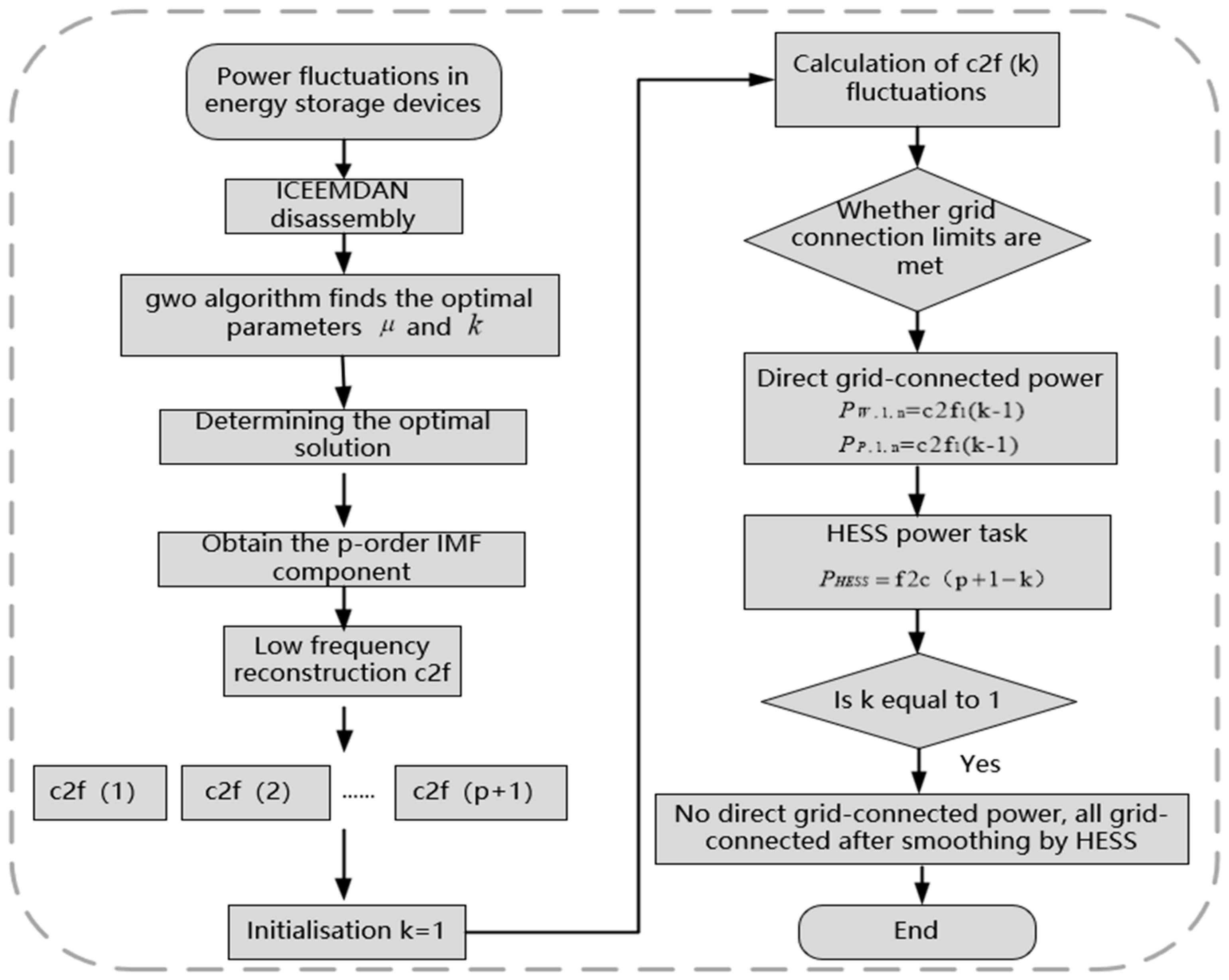
2.1.2. Power Decomposition Method for ICEEMDAN-Based Energy Storage Systems
The raw power signal is processed using ICEEMDAN to obtain the intrinsic mode functions of each order. Since processing each IMF component separately would result in unnecessary workload, they are reconstructed into low-frequency components and high-frequency [
25] components in combination with power fluctuation limits. The low-frequency components are assigned to gas energy storage and the high-frequency components are used for electrochemical energy storage power tasks [
26], as shown in Equation (1).
where,
and
are the power raw signal, gas storage energy component, and electric storage power task at time n, respectively.
IMF reconstruction involves calculating the low-frequency and high-frequency components by superimposing the components of the low-frequency band and high-frequency band according to a given index. The reconstruction methods are divided into high-frequency reconstruction (f2c) and low-frequency reconstruction (c2f). High-frequency reconstruction generates high-frequency reconstruction components of each order from top to bottom. The specific reconstruction method is shown in Equation (2).
Low-frequency reconstruction: The low-frequency reconstruction components of each order are generated by stacking from bottom to top according to the decomposition result. The reconstruction method is shown in Equation (3).
Based on the above signal decomposition and signal reconstruction, power distribution is completed through the power signal. The specific power decomposition strategy flowchart is shown in
Figure 2 below.
In this paper, the fluctuation of the power signal is defined as the difference between the maximum and minimum power in a specified time interval. The limit of the power fluctuation is shown in Equation (4):
where
is the power value during the
m time period of the
order component of the low-frequency reconstruction component;
is the time interval, set to 10 min here; and
is the fluctuation limit, set to 5% of the installed energy storage capacity for the 10 min fluctuation limit here.
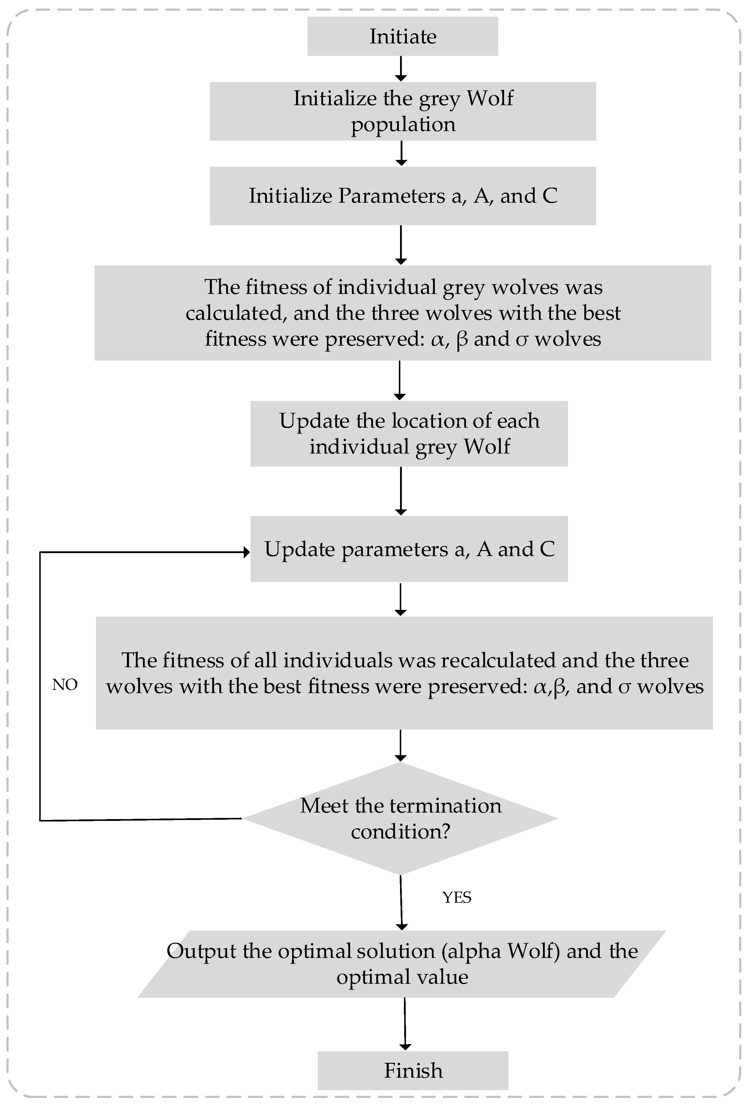
2.1.3. Optimization of ICEEMDAN Parameters Based on the Grey Wolf Algorithm
During the process of power decomposition using the ICEEMDAN method, the noise ratio parameter μ and the high/low-frequency power boundary point k have significant impacts on the final power decomposition results. Therefore, this paper employs the grey wolf optimizer (GWO) [
27] to optimize these two parameters, aiming to obtain the optimal signal-to-noise ratio parameter μ and high/low-frequency power boundary point k. This will maximize the system’s response capability to power changes, thereby enhancing the accuracy and efficiency of power allocation in the hybrid energy storage system. The steps are as follows:
In the GWO algorithm, the first step is to set the population size N and the dimension of the optimization problem D. For the optimization of ICEEMDAN, two key parameters need to be optimized:
The signal-to-noise ratio parameter μ (used to regulate the amount of noise in ICEEMDAN, which affects the accuracy of the IMF decomposition).
The frequency cut-off point k (used to determine the division of the low- and high-frequency components in order to allocate the low-frequency portion to the gas energy storage system and the high-frequency portion to the electrochemical energy storage system).
Therefore, dimension D of the GWO can be set to 2, corresponding to the interval of the values of
μ and
k, respectively [
28].
The positions of the initialized grey wolf populations (i.e., the initial values of
μ and
k) are random values:
where
μ and
k are randomly chosen initial values in the appropriate intervals, respectively.
- 2.
Adaptation assessment.
For each individual grey wolf , the fitness value is calculated based on its position (i.e., the adjusted parameters). The selection of the fitness function is based on the objective of the optimization. In this paper, the objective is to optimize the power allocation responsiveness of the hybrid energy storage system. The following two aspects are considered:
- (1)
Power allocation error: a measure of how well the power allocation results of the LF and HF IMF signals match the actual demand of the energy storage system.
- (2)
System responsiveness: Capacity and power responsiveness of energy storage devices to power volatility.
Therefore, the fitness functions are, respectively, as follows:
where
is the power allocation error,
is the system responsiveness, and
are the weighting factors, which are adjusted according to the actual demand.
- 3.
Determination of the optimal solution.
After going through the adaptation assessment, the three best-adapted individual grey wolves are selected. They are labelled, respectively, as follows:
α-wolf (optimal solution): This wolf represents the best μ and k parameter values, which can maximize the power allocation effect of the energy storage system.
β-wolf (second-best solution): This wolf represents the second-best parameter values.
σ-wolf (third-best solution): This wolf represents the third-best parameter values.
These individual parameters will be used as a reference for updating the position of other grey wolves in the next step.
- 4.
Position update.
For each individual grey wolf X
i, the location update formula is as follows:
where
A and
C are the calculation coefficients. Specifically,
Here, a is a linearly decreasing factor, gradually decreasing from 2 to 0, and are random numbers ranging between [0, 1].
The position of α-wolf represents the optimal solution, i.e., the best μ and k values.
During the updating process, the individual grey wolves approach the optimal solution (α-wolf), adjusting the values of μ and k so that the decomposition results are more in line with the requirements of the hybrid energy storage system.
Through the iterative process, the parameters of the grey wolves (μ and k) are gradually approaching the optimal values, which improves the accuracy and power allocation capability of the ICEEMDAN decomposition.
- 5.
Repeat iterations.
The processes of fitness evaluation, optimal solution selection, and position updating are continued until the maximum number of iterations is reached or the fitness values satisfy the predefined optimization criteria. The optimal μ and k parameters are finally obtained, which effectively improves the responsiveness of the hybrid energy storage system to power variations.
The specific grey wolf algorithm flowchart is shown in
Figure 3 below.
2.2. Electro-Gas Energy Management Strategy
On the basis of the charging and discharging power constraints and storage state constraints for electrochemical and gas energy storage, as well as the operational characteristics of alkaline electrolyzers, this paper constructs a corresponding electric–gas energy management strategy that can effectively schedule energy charging and discharging among various energy storage systems while improving system operational efficiency.
2.2.1. Impulse and Discharge Power Constraints
The operating conditions of the alkaline electrolyzer are summarized as follows:
High-power operation condition: When the input power reaches 100~120% of the rated power, it belongs to the high-power operation condition.
Low-power operation condition: When the input power is lower than 20~25% of the rated power, it belongs to the low-power operation condition. If the electrolyzer is in the low-power operation condition for a long time, there may be the risk of explosion.
Rapid power adjustment condition: The alkaline electrolysis tank can achieve a wide range of power adjustment at the minute level under the condition of ensuring safe and stable operation.
In the coordinated operation of electric–gas hybrid energy storage systems, full use can be made of the advantages of high-power operation and fast power regulation, and at the same time, in order to maintain operational safety and stability, operating under low-power conditions should be avoided.
The traditional HESS divides the battery state of charge (SOC) of power-based energy storage into three intervals: when the HESS is in the charging state , the electrolytic tank is activated in the interval , and the electrochemical storage is activated in the interval ; when the HESS is in the discharging state , the electrochemical storage is activated in the interval , and the gas turbine is activated in the interval . The energy management strategy takes into account the power and capacity constraints of the energy storage system and avoids overcharging and overdischarging, but its drawbacks are also obvious:
The complementary mechanism of the two types of energy storage is simply superimposed, without considering the operating characteristics of the electrolysis tank, which may cause wind abandonment or the electrolysis tank to operate under low-power conditions for a long time during special periods.
It relies on electrochemical energy storage to smooth out fluctuations and lacks an energy complementary strategy; thus, its SOC can be in a limit state for a long time, resulting in lower power and capacity utilization.
2.2.2. Electro-Gas HESS Energy Management Strategy
This paper proposes an electric–gas HESS energy management strategy that takes into account the operating characteristics of alkaline electrolyzers and copes with the low-power operation of alkaline electrolyzers by reinforcing the complementary mechanism between electrochemical energy storage and gas energy storage. The basic principles of the strategy include the following:
Considering the importance of electrochemical energy storage in guaranteeing the smooth operation of the system, the electrochemical energy storage SOC is kept at an intermediate level as much as possible, so that it has enough power and capacity to smooth out fluctuations.
- 1.
The strategy is based on gas energy storage, supplemented with electrochemical energy storage. In the division of the SOC interval, and , two splitting points, are added to avoid the excessive use of electrochemical energy storage, and at the same time, electrochemical energy storage is used to ensure that the electrolysis tank can be operated safely.
The logical flow of the energy management strategy proposed in this paper is shown in
Figure 4.
Based on traditional operation modes, the proposed strategy adds the following special operation modes.
Mode 1: When the system satisfies
The electrochemical energy storage discharge provides differential power for the operation of the electrolyzer, which avoids shutting down the electrolyzer and allows it to operate at minimum power.
Mode 2: When the system satisfies
Located in the start–stop buffer zone of the electrolyzer at this point, this operating mode serves two purposes. One is to widen the operating zone of the electrolyzer, the other is to maintain the SOC state at an intermediate level. There are three operation scenarios, as follows:
Scenario (i): When the electrochemical energy storage is in a charging state at the moment of n − 1, and when the electrochemical energy storage is charged above the moment of n, the electrolyzer will be turned on in advance.
Scenario (ii): When the electrochemical energy storage is discharged to support the operation of the electrolyzer at n−1, the electrochemical energy storage will no longer supply power to the electrolyzer at time t, avoiding prolonged operation in Mode 1, which will lead to a continuous decline in SOC.
Scenario (iii): When the electrochemical storage discharge compensates for the negative at n − 1, the electrolyzer is switched on at n, which not only broadens the operating range of the electrolyzer, but also avoids the continuous charging of the electrochemical storage.
Mode 3: When the system satisfies
Start the fuel cell and run it at rated power , charging the electrochemical storage while compensating for .
Mode 4: When the system satisfies
At this time, the focus is on the start–stop buffer of the fuel cell. When n − 1 is in the start-up state at any time, it continues to maintain its running state. When n − 1 is in the off state at any time, it keeps the fuel cell in the off state. The function of this working mode is to avoid the fluctuation in energy storage SOC near and the phenomenon of the repeated charging of fuel cells.
The main differences between the strategy proposed in this paper and the conventional strategy are as follows:
In the specific operation mode of this strategy, the electrochemical energy storage can be discharged to support the operation of the electrolyzer. In some cases, it can also be forced to start the electrolyzer to prolong its operation time and reduce wind abandonment.
Under this strategy, when the SOC is at a low level and hybrid storage discharge is required, the fuel cell can charge the electrochemical storage to maintain the SOC in a good condition.
2.3. Electricity–Gas–Heat Integrated Energy System Model
The main coupling parts of the electric power system and natural gas system are P2G equipment [
29] and CHP equipment [
30], which can effectively realize the two-way coupling of the electric–gas system.
Electricity-to-gas technology includes two chemical processes: the electrolysis of the water reaction 2H2O → 2H2 + O2 and methane synthesis reaction CO2 + 4H2 → CH4 + 2H2O. The electricity-to-gas process not only strengthens the coupling between the two energy networks, but also consumes electricity from renewable energy sources, such as wind power, which is equivalent to an artificially increased electrical load when connected to the system, and wind power that cannot be consumed can be reused, thus improving the efficiency of wind power utilization. The relationship between P2G consuming electric energy and natural gas production is shown in Equation (13). The energy and volume of natural gas produced can be converted according to its high calorific value, and the relationship is shown in Equation (14); the volume of natural gas that can be produced in time period t needs to meet the upper and lower constraints of Equation (15).
where
and
are the energy and volume values obtained from the conversion of electricity to gas at moment t, respectively;
is the electrical energy consumed by the P2G process (which is considered a load in the electricity network and can also be referred to as the electrical load of P2G); and
is the high calorific value of natural gas.
- 2.
CHP.
When other heat supply equipment cannot meet the demand of heat load, CHP is used to make up for the shortfall and maintain the balance of heat energy supply and demand.
Gas turbines are the core equipment in CHP, and can achieve great improvements in primary energy utilization efficiency and reduce the energy consumption of the energy system so as to realize energy saving and consumption reduction for users. Generally speaking, the mathematical model of a gas turbine can be expressed according to its fuel consumption and its power characteristics. In the model of this paper, the relationship between fuel and the output of the gas turbine can be expressed by Equation (16):
where
is the amount of natural gas consumed during the operation of the gas turbine;
is the low calorific value of natural gas;
is the net electrical power output of the gas turbine; and
is the efficiency of the gas turbine in generating electricity.
3. A Multi-Objective Planning Optimization Model for Integrated Energy System with Multiple Timescales Based on Hybrid Energy Storage
This section first proposes a system planning strategy based on long- and short-term electricity demand and the operational status of the system. Subsequently, based on this planning strategy, a multi-objective planning optimization model for an integrated energy system is constructed, with objective functions related to economy, environmental protection, and efficiency. The NSGA-II algorithm is selected to solve this model in order to obtain the optimal solution.
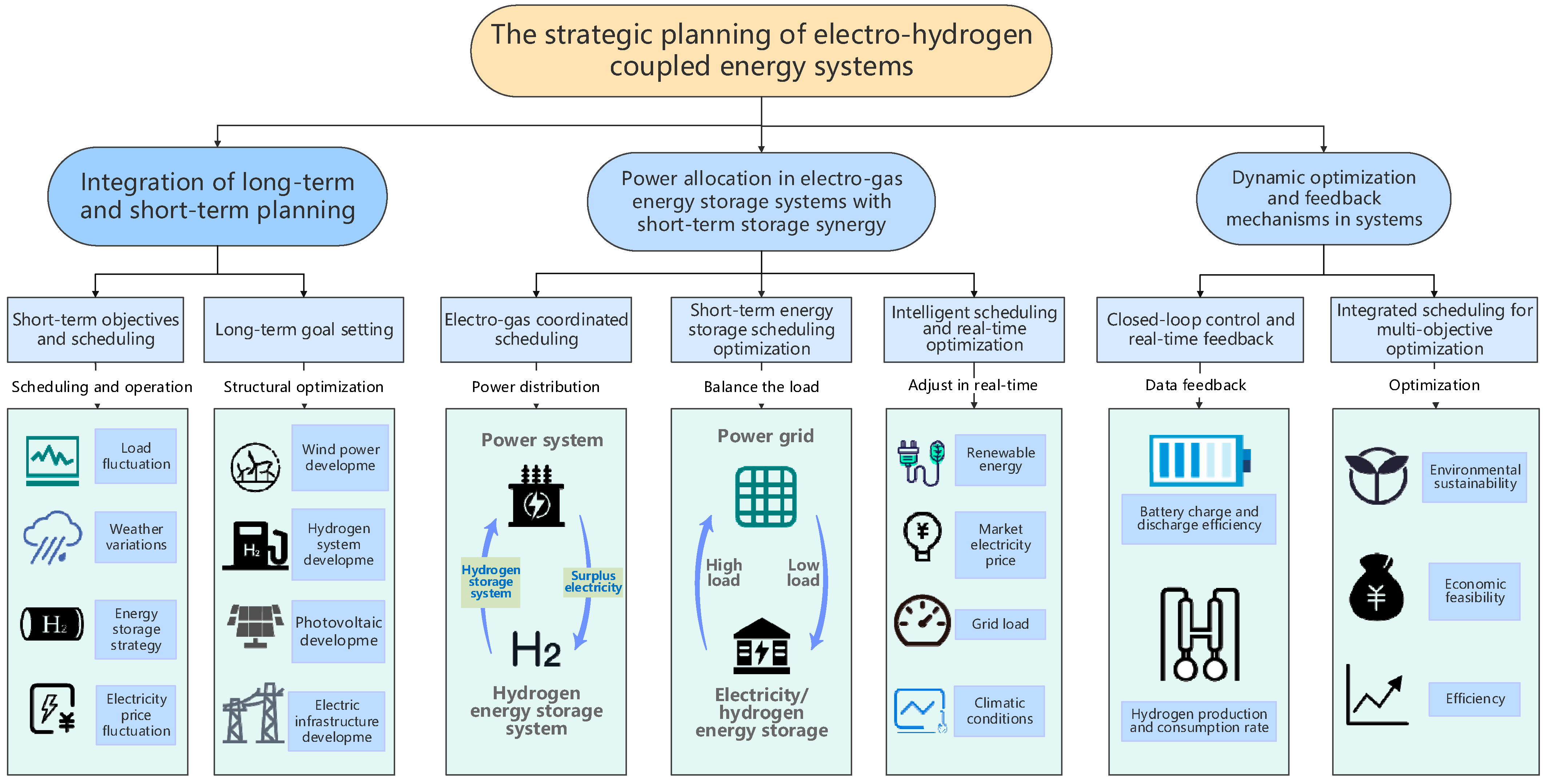
3.1. Planning Strategy
Planning strategies for electrically coupled energy systems not only focus on the long-term development of the system, but also need to flexibly respond to short-term power demand and operating conditions. By combining long-term strategic goals with short-term operational adjustments, an effective planning strategy can optimize the system’s energy use strategy and power allocation on different timescales and improve the overall efficiency of the system. The specific planning strategy is shown in
Figure 5 below.
- (1)
Integration of long-term and short-term planning.
Long-term goal setting: Long-term planning focuses mainly on the structural optimization of the system and the energy transition, with the objectives of enhancing the green transition capacity of the energy system, achieving low carbon emissions, and diversifying energy sources. Specific measures include the construction of efficient renewable energy generation facilities (e.g., wind power, photovoltaic power generation, etc.), as well as natural gas production and storage facilities, and ensuring complementarity and coordination among various energy sources. Long-term objectives also include the construction and improvement of infrastructure, such as natural gas pipeline networks and electricity transmission networks.
Short-term objectives and scheduling: Short-term planning focuses on the daily operation of the system and energy optimization strategies, focusing on short-term load demand satisfaction, economic optimization, and system reliability improvement. This includes optimizing power during periods of peak grid demand through the synergy of short-term electric–gas energy storage systems, including battery storage and natural energy storage, to safeguard load demand and maximize economic efficiency. Short-term plans also need to be responsive to price fluctuations in the power market, load fluctuations, and weather conditions. Therefore, short-term optimization strategies need to be flexible and able to adjust the charging and discharging strategies of the storage system in real time.
- (2)
Power allocation in electro-gas energy storage systems with short-term storage synergy.
The synergy of long- and short-term energy storage systems is crucial in electrically coupled energy systems, especially in electric–gas storage systems, where storage facilities can help to achieve a rapid response and balance the production and demand of electricity and natural gas. The operation of the energy storage system can be optimized through effective power allocation strategies while ensuring economy and reliability. Specific measures are as follows:
Electricity–gas energy storage system synergy strategy: In electrically coupled systems, electric–gas energy storage systems (electric and natural gas energy storage) can work in synergy to achieve optimal power distribution. Excess power from the electrical system can be used for the electrolytic production of natural gas, while the natural gas storage system can support the electrical system. When power demand exceeds generation capacity, natural gas can be reconverted to electricity to balance the system load. This electric–gas storage synergy not only reduces the peak-to-valley variance of the power system, but also improves energy flexibility and responsiveness in system operation.
Short-term energy storage scheduling optimization: Optimization strategies for short-term energy storage should take into account the volatility of power loads, changes in electricity prices, and the charging and discharging status of energy storage facilities. When the load on the grid is low and there is excess renewable energy generation, battery storage and natural energy storage systems can take advantage of this period to charge and store excess energy. During peak loads on the grid, through the rational optimization of these storage systems, the stored electricity or natural gas can be released into the grid to balance load fluctuations and ensure the stability of the power supply.
Intelligent scheduling strategy: In order to realize the efficient synergy of the electric–gas energy storage system, an optimization strategy based on the NSGA-II algorithm is used. The algorithm dynamically adjusts the charging and discharging strategies of the energy storage system based on data (e.g., grid load, climate conditions, renewable energy generation forecasts, market electricity prices, etc.) at different moments throughout the year. Through the optimization algorithm, the economic benefits of the energy storage system can be maximized, the energy utilization rate can be improved, and the operation cost can be reduced.
- (3)
Dynamic optimization and feedback mechanisms in systems.
Integrated multi-objective optimization: In the process of combining long-term and short-term plans, optimizing the objective function (including economy, environmental protection, energy efficiency, etc.) involves weighing the relationships between the objectives. The NSGA-II algorithm for multi-objective optimization is used to find the optimal balance between multiple objectives and maximize the overall efficiency of the energy system.
3.2. Objective Function
The planning and optimization objectives of the integrated energy system are divided into three aspects: economy, environmental friendliness, and efficiency.
The specific objectives are explained as follows:
The economic goal of the system can promote the rational allocation of energy at the economic level and guide the system to choose a cost-effective energy supply combination and operation mode. In this paper, the economic objective is to minimize the annual total cost of the integrated energy system, which consists of the cost of power purchase, equipment maintenance, equipment purchase, and the penalty for wind and light waste.
The objective function is shown below:
where
denotes system maintenance cost, yuan;
denotes grid power purchase cost, yuan;
denotes equipment maintenance cost, yuan;
denotes equipment purchase cost, yuan; and
denotes wind and light abandonment penalty cost, yuan.
- (1)
The cost of electricity purchased on the grid can be calculated as follows:
where
denotes the purchase price of electricity in time period
t, yuan;
denotes the purchase power of electricity in time period
t, kW;
denotes the sale price of electricity in time period
t, yuan;
denotes the sale power of electricity in time period
t, kW; and
denotes the period of electricity purchasing.
- (2)
Equipment maintenance costs can be calculated as follows:
In the above equation, i is the type of equipment; is the rated capacity value of equipment i; is the unit investment cost of equipment i; is the use of time of equipment i; and is the discount rate. This paper take 0.04.
- (3)
Penalty costs for wind and light abandonment can be calculated as follows:
where
is the consumption penalty factor,
is the penalty cost of abandoned light, and
is the penalty cost of abandoned wind.
- 2.
Environmental.
The environmental friendliness of the model is mainly measured by the carbon emission index. The pursuit of environmental protection in the system can drive the energy industry to transition towards green and low-carbon directions, fostering cleaner and healthier ecological environments and sustainable energy utilization patterns. At the same time, it is also beneficial to the long-term operation of the park. The calculation formula is as follows:
where
is the total carbon emissions of the system, kg;
represents the total carbon emissions in the time period that has occurred, kg;
represents the total carbon emissions of the optimized scenario from the beginning of the time period to the end of the cycle, kg;
represents the amount of electricity purchased from the distribution grid of the integrated energy system and the amount of gas purchased from the external gas grid, m
3; and
represent the carbon dioxide conversion factor per unit of electricity and the carbon dioxide conversion factor per unit of gas, respectively.
- 3.
Efficiency.
The energy efficiency objective of the system can enhance the operational efficiency of the energy system, enabling the close coordination of energy production, conversion, transmission, and distribution with user demand. This objective guides the system to allocate energy quickly and accurately based on dynamic demand, achieving the best match between energy supply and demand. The input energy in the IES is electrical energy from the grid and energy from energy networks external to the system. The output energy is the load demand of the user. In addition, renewable energy sources that are reasonably utilized by the system itself, such as wind, light, and air heat, are not included in the energy input. However, the loads that can be met by renewable energy sources are included in the energy outputs.
where
and
represent the input of electric energy and gas from the external pipeline network, kW;
and
represent the electric and thermal loads, kW, respectively;
and
represent the actual energy storage, kW, respectively, after taking into account the energy losses of batteries and other forms of energy storage;
and
represent the actual energy release, kW, respectively, after taking into account the losses of energy release from batteries and other forms of energy storage;
,
, and
represent the energy coefficients of electric energy, gas, and thermal energy; and
and
are the energy coefficients of the electric and thermal loads.
The energy coefficient for electricity is 1. The mathematical expressions for the energy coefficients of heat loads and gases are as follows:
where
is the ambient temperature, °C;
is the complete combustion temperature of the gas, °C; and
is the heat load temperature, °C.
3.3. Restrictive Condition
Integrated energy system planning and optimization must consider constraints, which are a key part of the integrated energy system. To meet the energy balance between energy consumption and production, the output of the equipment must meet the constraints of each piece of equipment. In order to meet the user’s energy needs, all devices and network nodes in the network must meet the requirements of stability and security, and at the same time need to take into account the interaction between the system and the external network. In summary, the model constructed in this paper mainly establishes constraints from three aspects: power balance constraints, equipment output constraints, and wind and light abandonment constraints.
- 1.
Power balance constraints.
- (1)
Electric load balance constraints can be calculated as follows:
where
is the power of the integrated energy system to buy electricity from the grid, kW;
is the power of the integrated energy system to sell electricity to the grid, kW;
is the output power of wind power generation, kW;
is the output power of distributed photovoltaic power generation, kW;
is the output power of CCHP power generation, kW;
is the power of the battery’s discharging power, kW; and
is the power of the battery’s charging power, kW.
- (2)
Heat load balance constraints can be calculated as follows:
where
is the heat exchange power between the heating company and the integrated energy system, kW;
is the heat pump output, kW;
is the air conditioner output, kW;
is the CCHP heat output, kW;
is the power of the heat storage system to release heat, kW;
is the heat load in the system, kW; and
is the power of the heat storage system to store heat, kW.
- (3)
Natural gas load balancing constraints can be calculated as follows:
where
is the power of the natural gas grid supplying the system with natural gas, kW;
is the power released by the gas storage system in the system, kW; and
is the power generation efficiency of gas-fired power generation, %.
- 2.
Natural gas load balance constraints.
- (1)
Energy production and conversion equipment output constraints.
The main energy production and energy conversion devices in the integrated energy system include CHP, wind turbines, photovoltaics, P2G, and electric boilers. Their output constraints are as follows:
where
is the upper output limit of PV, kW;
is the upper output limit of the wind turbine, kW;
and
are the upper and lower output limits of CHP, kW;
and
are the upper and lower output limits of the electric boiler, kW; and
and
are the upper and lower output limits of P2G output, respectively.
- (2)
Energy storage battery constraints.
The constraints of the energy storage battery mainly include charging and discharging power constraints, charge state constraints, and equilibrium constraints at the beginning and end states of the device, which are as follows:
where
denote the residual power of the storage battery at two time periods, respectively;
denotes the self-discharge rate of the storage battery, %/h;
and
are the minimum and maximum constraints of the residual capacity; and
and
are the maximum charging and discharging power, kW.
- (3)
Thermal storage tank constraints can be calculated as follows:
where
indicates the residual heat of the heat storage tank at the time, kJ;
indicates the heat loss rate of the heat storage tank, %;
indicates the heat storage capacity of the heat storage tank at the initial time, kJ;
indicates the heat charging capacity of the heat storage tank between the time periods, kJ;
indicates the exothermic heat between the time of
and the time of
, kJ;
is the ratio of the maximum permissible heat storage and the minimum permissible heat storage to the heat storage capacity; and
is the heat storage capacity, kW.
- (4)
Equipment output and climb rate constraints can be calculated as follows:
where
and
are the maximum and minimum values of the output of non-dispatchable equipment (e.g., wind turbines and photovoltaics), kWh, and
and
are the effective dispatch intervals of dispatchable units, kWh.
The following constraints exist when the integrated energy system issues dispatch plans to distributed energy devices:
where
and
are the power of the device at the current moment and the previous moment, kW, and
and
are the maximum power of the device allowed to rise or fall per unit of time, kW.
- 3.
Wind and light abandonment constraints can be calculated as follows:
where
is the maximum constraint on wind and light rejection power and
is the maximum constraint on the total amount of wind and light rejection in the system.
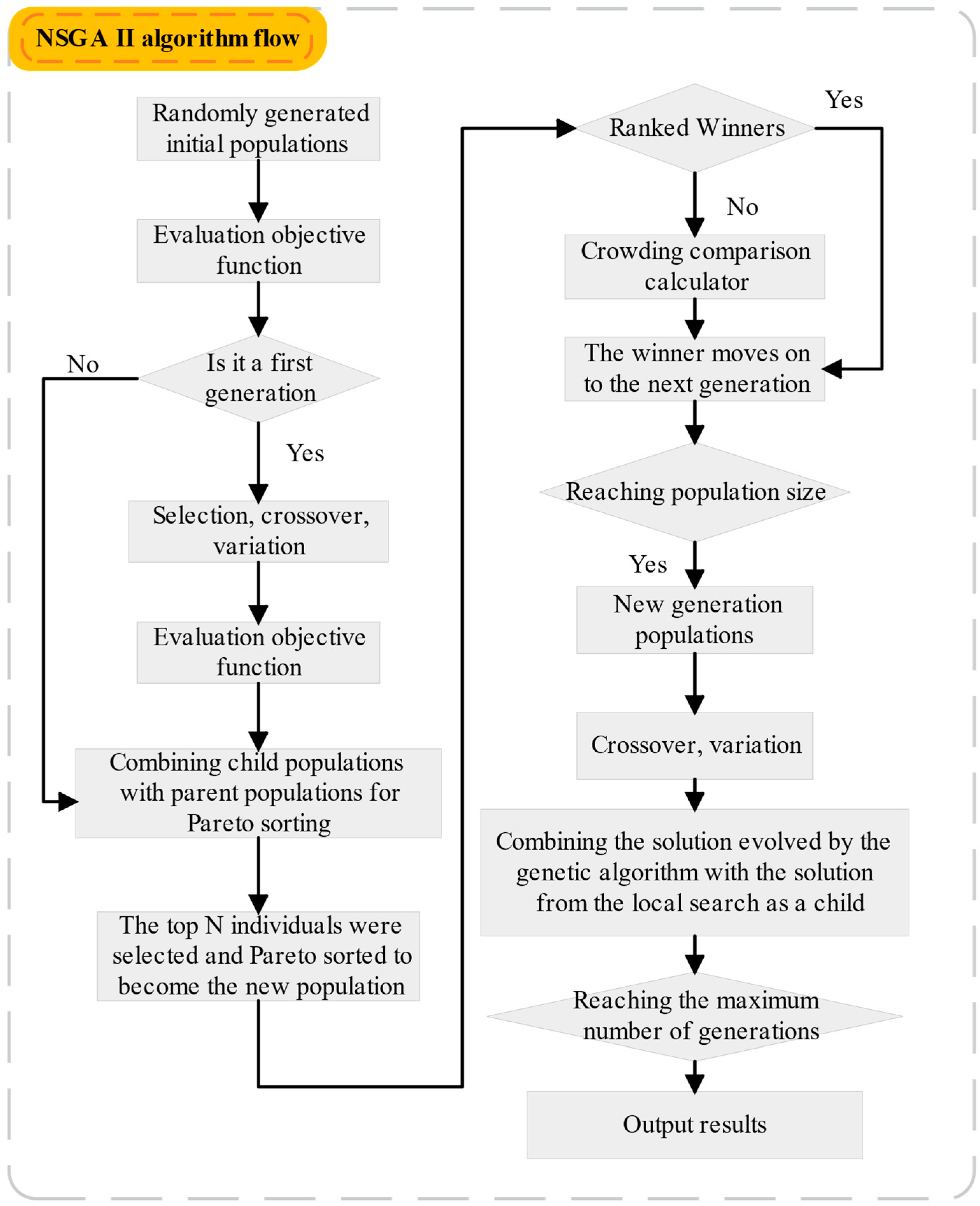
3.4. Solving Algorithms
The above model is solved as a classical multi-objective optimization problem involving many nonlinear and discrete stochastic models and uncertainties. The optimal solution of the problem often exists in the set of Pareto optimums that are jointly formed by multiple solutions. Therefore, the NSGA-II algorithm can be considered for the solution.
NSGA-II is a multi-objective optimization algorithm based on the Pareto optimal solution, which has the advantages of fast running speed and good convergence of the solution set. The algorithm uses a fast non-dominated sorting algorithm in the iterative process, so that the individuals in the Pareto set as a whole continue to the Pareto set.
In this paper, the configured capacity X of each device is set for optimization, and the set parameters also include the corresponding population R, the population size K, and the number of evolutionary generations
. The objective function is
and the individual crowding degree is
, which is calculated as follows:
where
is the value of the objective function of the next ranked individual and
and
are the maximum and minimum values of the objective function
of the individual in the Pareto class, respectively.
Through the above steps, the NSGA-II algorithm can search for a set of solutions with good diversity and convergence in the multi-objective optimization problem, providing multiple alternative solutions for the decision maker. The specific flow chart is shown in
Figure 6.
4. Example Analysis
This paper takes a park in Shanxi, China, as an example, and optimizes the configuration of the simulated park based on the integrated energy system planning optimization model established above. The park planning equipment includes an electric system, including photovoltaics, a wind turbine, a storage battery, and a power grid; a gas system, including a gas boiler, P2G, and a gas storage tank; and a thermal system, including an electric boiler and a heat storage tank. Among them, the energy supply of the park is mainly centered on electricity, making full use of wind, light, and other renewable energy sources to realize the energy supply of the park. The storage battery and heat storage tank have the functions of flattening the fluctuations in renewable energy, cutting peaks and filling valleys, and responding to peak and valley tariffs in the energy system. The park is equipped with large-scale information processing equipment, so it requires a high stability of thermal system energy supply. This section plans and optimizes the distributed energy equipment of the integrated energy system for a one-year period with hourly accuracy.
4.1. Energy Mix
The electric–gas–thermal integrated energy system mainly includes three parts: an electric system, a gas system, and a thermal system. Its structure is shown in
Figure 7. The electric system part mainly includes a wind turbine, photovoltaics, an external grid, a storage battery, P2G, and an electric boiler. The gas system part mainly includes P2G, a gas boiler, and a gas storage tank. The thermal system part mainly includes CHP, an electric boiler, and a heat storage tank.
Among them, CHP is a cogeneration technology that includes three parts: a waste heat recovery unit, a gas boiler, and a heat exchanger. In a cogeneration system, the steam discharged from a gas boiler generator set after generating electricity still contains a large amount of heat, which, if not utilized, will result in a significant loss of heat energy. The effective utilization of this heat for both power generation and heat supply increases the energy utilization efficiency by about double or more than that of power generation alone. CHP systems are able to utilize different grades of thermal energy in a graded manner, which improves the efficiency of energy utilization. The P2G equipment is mainly composed of an alkaline electrolyzer, which has the advantages of mature technology and low cost. As a piece of electrical conversion equipment, the alkaline electrolyzer has a strong ability to suppress fluctuations when used to stabilize the unstable power output of renewable energy.
In the electric system, wind turbines and photovoltaics convert clean energy to meet electric load demand directly. The energy storage battery is charged when the power is abundant and the electricity price is low for short-term energy storage. When wind turbines and photovoltaic power generation cannot provide enough energy and the electricity price reaches the peak to meet the demand of power load, they will be discharged. When there is a surplus of wind turbine and photovoltaic power to meet load demand and the storage battery is fully charged, the P2G equipment can convert the wind and photovoltaic power into natural gas, which is kept in long-term storage in gas storage tanks. Gas boilers convert natural gas directly into heat energy and supply heat load demand through heat exchangers. Electric boilers convert electricity directly into heat to meet the heat load demand. Thermal storage tanks store heat during the low load period of the heating period to improve the peaking capacity.
4.2. Basic Data
Considering the strong dependence of the park’s renewable energy equipment on environmental factors, this section obtains annual light intensity and wind speed variation curves from the China Meteorological Administration, as shown in
Figure 8 below.
Based on the data collected from the five transformers in the park, the park’s energy demand for electricity and heat throughout the year is shown in
Figure 9 below.
In the operation of the integrated energy system, external energy prices and carbon emissions directly affect the effect of operation optimization. In this case study, the emission coefficient is 1.33 kg/m
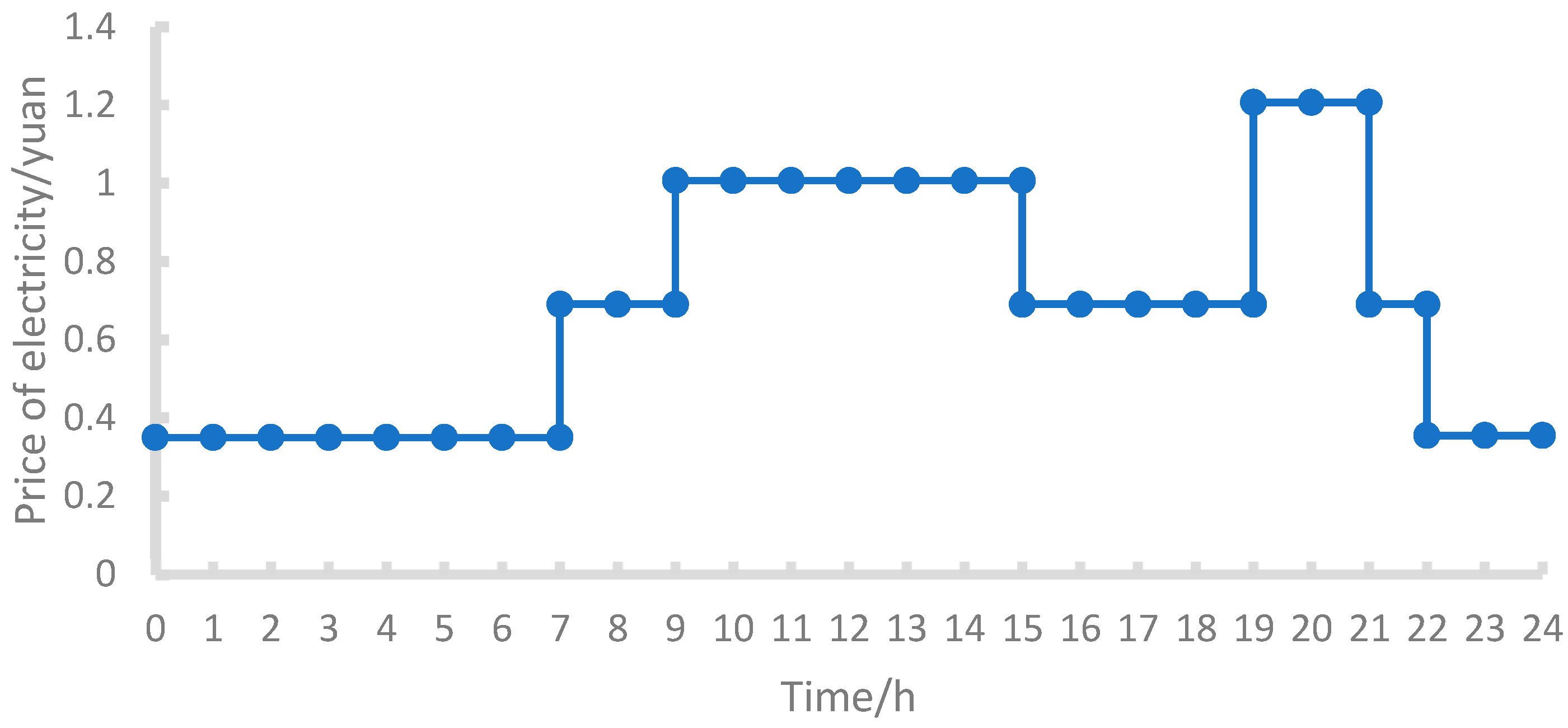
3. Energy price is an important factor affecting user participation in demand response. In order to facilitate the analysis of the degree of response of the integrated energy system to changes in energy prices, this paper studies the time-of-day tariffs of the park’s conventional power purchase prices, as shown in
Figure 10. The carbon conversion coefficient of grid power purchase is 0.272 kg/kWh, and the data come from the standards of the National Bureau of Statistics, using the calculation method of energy consumption in oil refineries.
The many types of equipment involved in the entire integrated energy system are summarized in
Table 3, which shows the key equipment parameters.
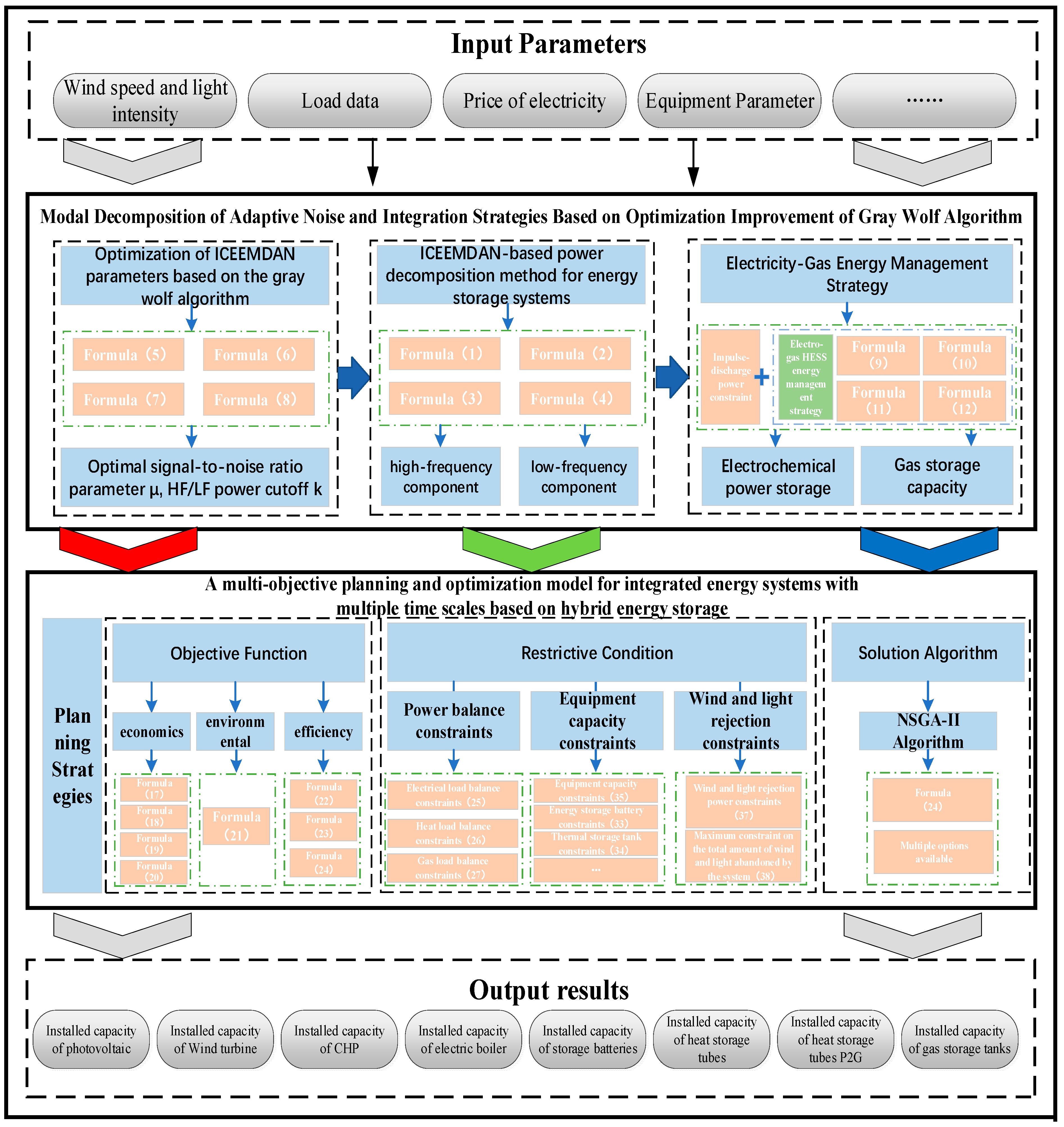
4.3. Program Scenario Design
According to the above proposed planning method of the electric–gas–heat integrated energy system based on long-term and short-term energy storage collaboration, this paper designs a simulation scheme for hybrid energy storage power distribution and integrated energy system planning optimization, respectively. The system simulation scheme mainly includes three important components: (1) Simulation parameter input, i.e., all relevant parameters involved in the input model in the early stage of scheduling and optimization, such as resource endowment parameters, park load data, park equipment parameters, energy price, etc. (2) Hybrid energy storage power allocation. Based on the input power data, the power is allocated based on the optimized and improved adaptive noise and integrated strategy mode decomposition method of the grey wolf algorithm under the corresponding constraints. (3) Integrated energy system planning and optimization. Based on the input simulation parameters, under the corresponding constraints, the NSGA-II algorithm is adopted for economy, environmental protection, and energy efficiency. The model solving process is shown in
Figure 11.
Considering the need to verify the validity of the model constructed in this paper, two scenarios are set up as comparisons, with specific settings as follows:
Scenario I: Basic Scenario.
Scenario I is the base scenario of this study, which mainly focuses on the application of the electro-thermal coupling system and does not introduce the electro-gas coupling energy storage system or the hybrid energy storage strategy. This scheme aims to ensure that the power system can operate smoothly and avoid power wastage, even if the storage capacity is insufficient or the charging rate is limited. The system is designed to supply thermal loads by converting excess wind–gas electricity into thermal energy, or to store surplus electricity as thermal energy when the storage system reaches its charging limit. The following specifics are noted:
- (1)
Conversion to thermal energy when the storage capacity is insufficient: When the battery storage system (e.g., battery pack) is full or can no longer be charged, the remaining electricity will be converted to thermal energy through an electric boiler to supply thermal loads. This method can avoid the waste of electric energy and enhance the fulfillment rate of heat load to a certain extent.
- (2)
Conversion to thermal energy when the charging rate is insufficient: In case the battery charging rate is insufficient to meet the load demand, the system will prioritize the conversion of excess power to thermal energy through the electric boiler instead of continuing charging. This avoids wastage of power due to slow or inefficient battery charging and effectively utilizes the available power to meet the thermal load demand.
Scheme II: Optimization scheme.
Scheme II further introduces the electro pneumatic coupling energy storage system on the basis of the basic scheme and combines the intelligent optimization strategy to optimize the power allocation strategy of the hybrid energy storage system through the grey wolf optimization algorithm and the adaptive noise integration empirical modal decomposition (EMD) method, so as to enhance the system’s responsiveness and response efficiency in the dynamic environment. Compared with Scheme I, Scheme II realizes the cooperative work of electric power and gas energy storage through the electric–gas coupling system, and by dynamically adjusting the power allocation between battery energy storage and natural gas energy storage, it more effectively balances the advantages of different energy storage modes and significantly improves the overall efficiency of the system. The scheme can not only regulate the conversion between electric power and natural gas energy storage more flexibly, but also can optimize the system’s resource allocation and further enhance new energy consumption capacity and system economy.
The program design comparison table is shown in
Table 4 below.
4.4. Algorithm Verification
Based on the electric–gas energy management strategy proposed in
Section 2 and the multi-objective planning optimization model for integrated energy systems with hybrid energy storage across multiple timescales constructed in
Section 3 of this paper, Matlab 2021a software is used for simulation analysis. The initial population size is set to 1000, and the number of iterations is set to 400. To highlight the superiority of the NSGA-II algorithm, this paper also employs the Genetic Algorithm (GA) and Particle Swarm Optimization (PSO) algorithms for comparison, obtaining their respective operational results. The iteration count, global optimization capability, solution time, and scheme cost obtained are shown in the table below. The results indicate that in terms of economic performance, the optimal scheme obtained by the NSGA-II algorithm is the most economical. Overall, compared to the QPSO algorithm, the NSGA-II algorithm has a shorter solution time, is less prone to getting stuck in local optima, and significantly improves computational efficiency. A comparison of the optimization results of the three algorithms is shown in
Table 5 below.
4.5. Results of the Optimization Scheme
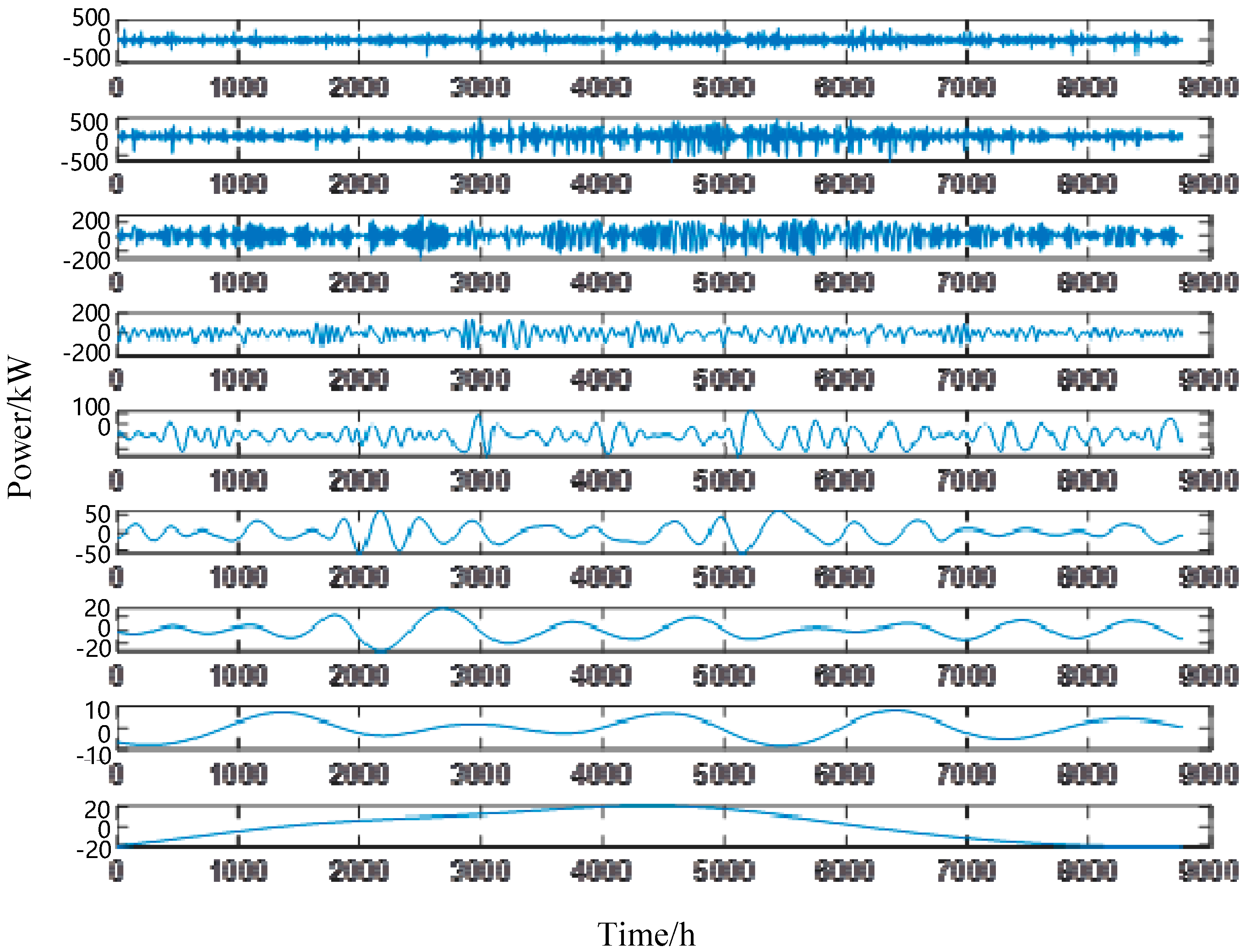
We retrieved the various output data from the case study presented in this paper and plotted the curves of each IMF component and the residual curve based on the GWO-improved ICEEMDAN algorithm proposed in
Section 2.1, as shown in
Figure 12 below.
In terms of the installed capacity of each piece of equipment, the installed capacity after electrical coupling optimization is shown in
Table 6 below.
After optimization, the overall utilization rate and consumption rate of new energy in the integrated energy system have been improved, and the installed capacity of the heat and power storage equipment has been reduced. On the one hand, this reduces the energy storage pressure of the electrical system and thermal system; on the other hand, it also reduces the operation and maintenance cost of the system. The installed capacity of the main coupling equipment of the system is reduced to varying degrees, which indicates that with the addition of P2G and a gas storage tank in the gas system, the output pressure of the system to each single piece of equipment is relieved, and the coordination stability of the system is improved.
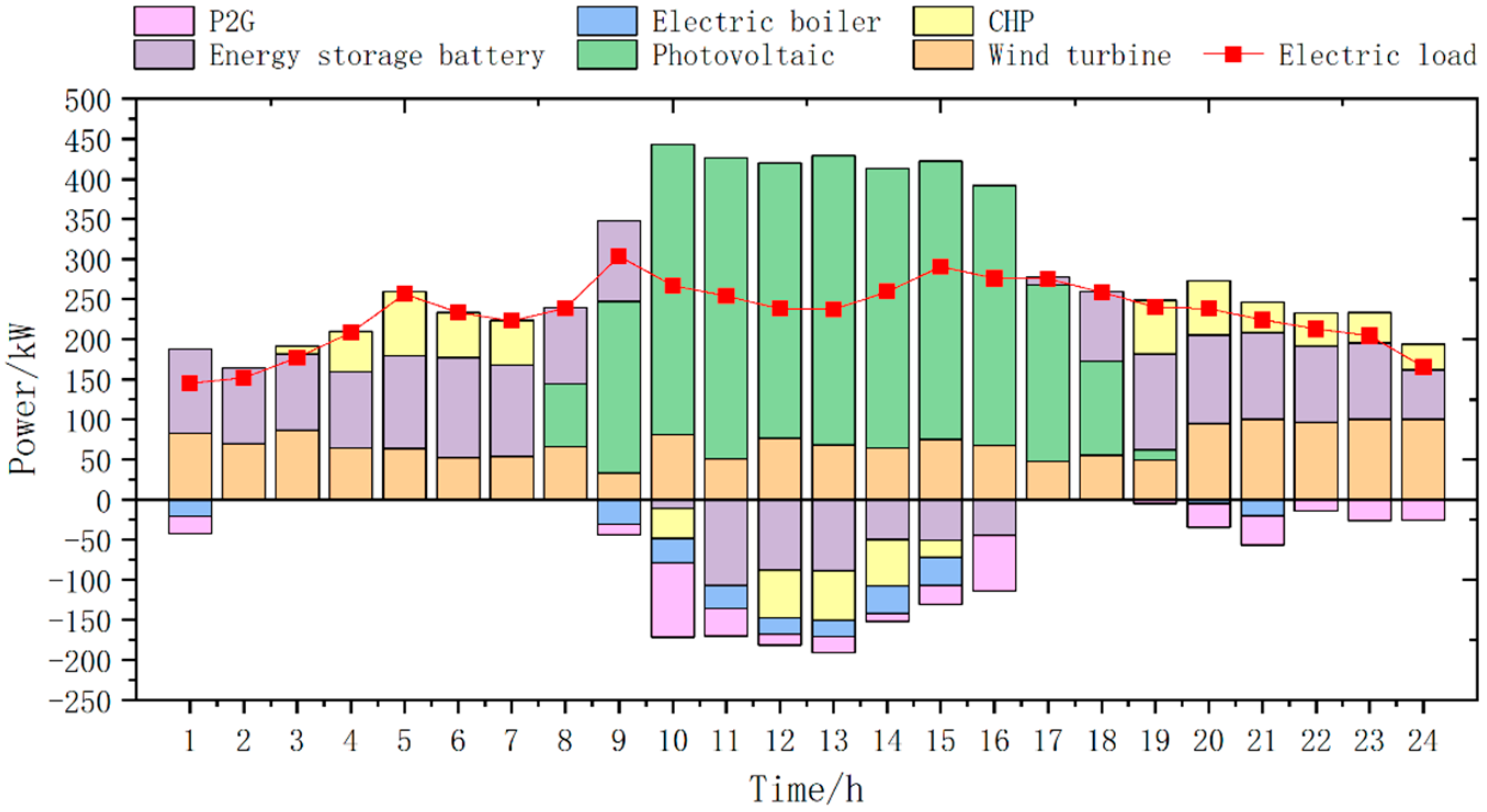
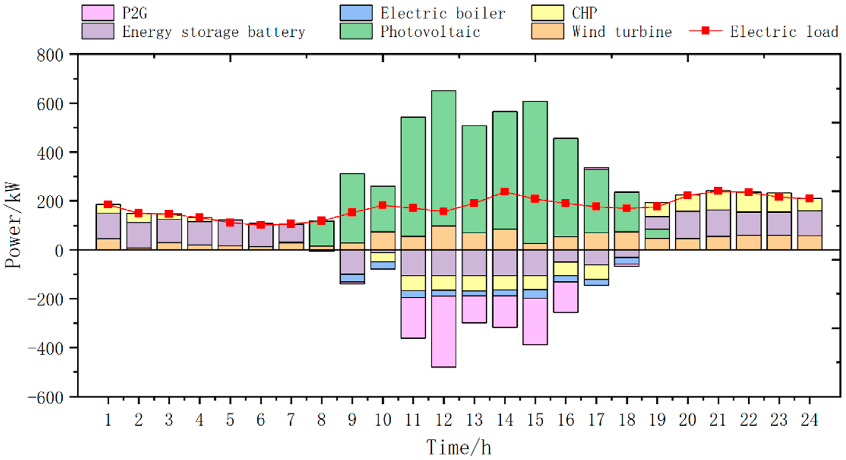
In the electric system, in addition to consuming renewable energy generation from photovoltaics and wind turbines, the storage battery also takes advantage of the tariff difference, charging at night at valley tariffs, discharging at daytime peak tariffs, and relying on the grid to deliver the rest of the power. In the gas system, the P2G equipment can convert wind and photovoltaic power into natural gas and store the energy for a long time in a storage tank. The following figures show the demand and the output of each piece of equipment after the optimization of the scheme.
As can be seen in
Figure 13,
Figure 14 and
Figure 15 below, in terms of wind power consumption, before optimization, in order to meet the electrical load required of the situation, in addition to the use of electric boilers to convert wind power into heat to supply thermal loads, there are still surplus wind power resources, and there is a large amount of abandoned wind and light. This is because, in the pre-optimization electric system, only the battery can consume wind power; if the battery has been rated, power charging will lead to its capacity being too large. Ambassador system cost is too high, and the advantageous consumption of wind power is insufficient. Therefore, the system prefers to discard wind and light rather than letting the battery charge at rated power. After optimization, the system can use P2G to convert wind power to natural gas, and combined with the hybrid storage power allocation method, wind power can be converted to natural gas more efficiently, which effectively reduces the phenomenon of wind and light abandonment. Compared with the pre-optimization, the overall efficiency of the system is significantly improved, and the ability to consume wind and solar power is significantly strengthened.
In medium- and long-term peaking, such as when continuous rainy weather is encountered, photovoltaic output is insufficient to cause cross-day peaking pressure. In the north and in the winter, wind speed and wind volume create a large fan output, while in summer, wind speed and wind volume have a small fan output, causing cross-season peaking pressure. Before optimization, when the new energy output is insufficient due to the limitation of battery capacity, the energy demand required for medium- and long-term system peaking cannot be provided, and to meet the load electricity must be bought through the grid, which greatly increases the economic cost and carbon emissions. After adding electrical thermal coupling, the natural gas stored in the gas network through the storage tank can be used to supply electricity and heat through CHP to meet the load, which reduces the economic cost in terms of economy, reduces carbon emissions in terms of environmental protection, and improves the utilization rate of new energy in terms of energy efficiency compared with the pre-optimization state.
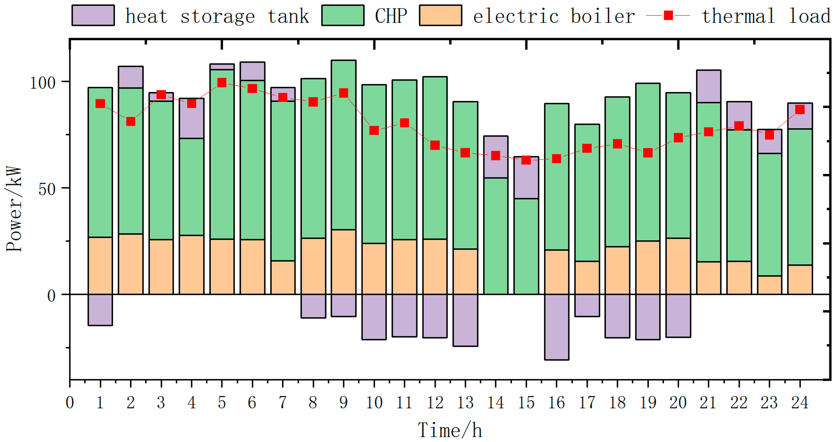
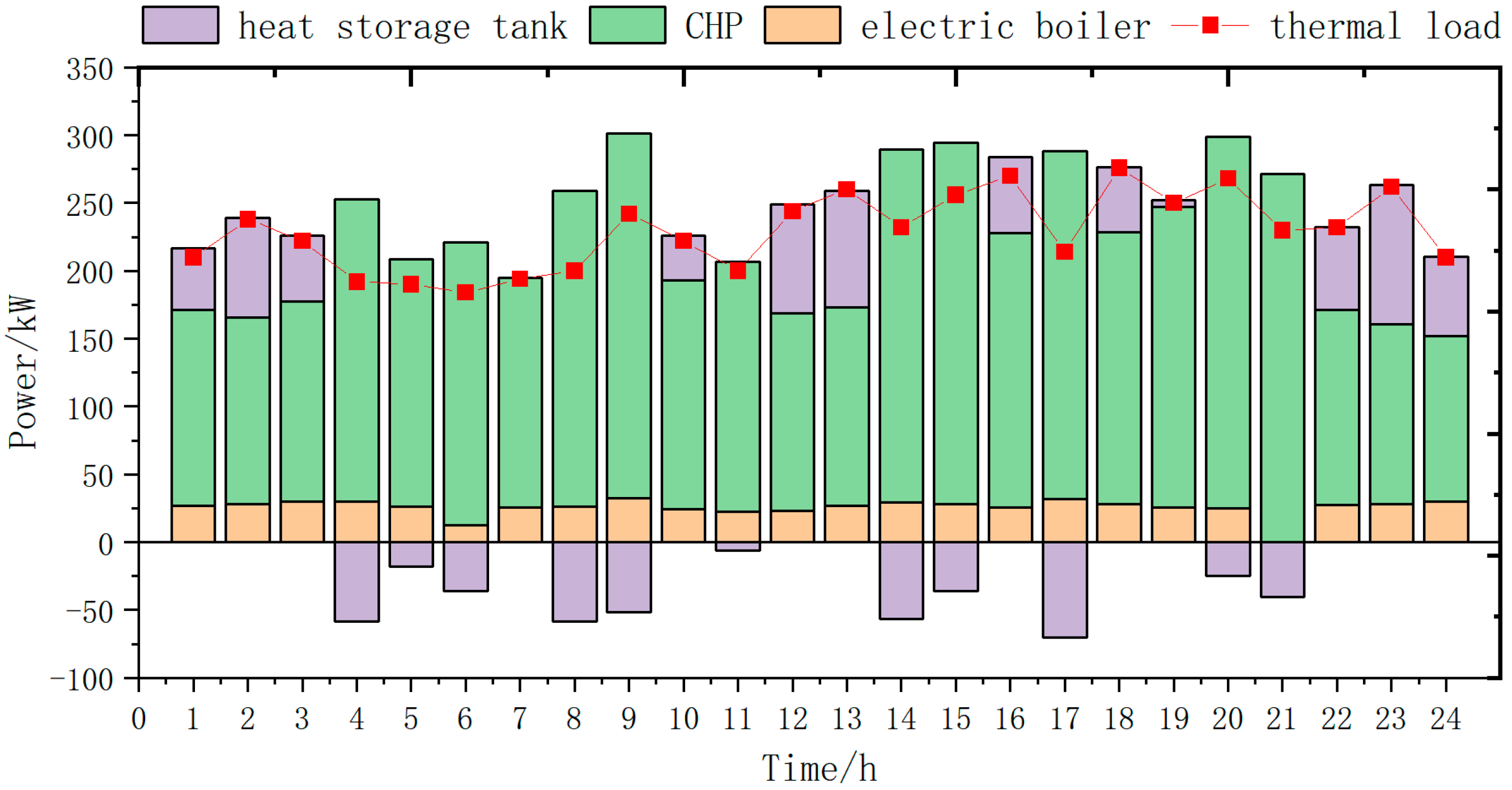
In the heat system, the electric boiler is used as the basic load supply equipment, with the characteristics of high economy and stable energy supply. On this basis, the residual heat from the gas boiler is used to supplement the load gap and cope with the network load fluctuation, and the heat storage tank is used as the energy storage guarantee. The following figures show the optimized demand of the program and the output of each device.
As can be seen in
Figure 16,
Figure 17 and
Figure 18 below, in the conventional thermal system, CHP equipment, an electric boiler, and a heat storage tank are involved in the whole heat cycle, and the heat storage tank is used as a heat storage device to store heat during the low load period of the heating period and to release heat during the peak period. Before the electrical–thermal coupling optimization, the whole system lacks P2G electricity-to-gas equipment, and most of the surplus power generation from wind power and photovoltaics is deposited into the storage battery or discarded, which results in a large amount of wasted energy, a single form of energy conversion, and poor energy complementarity. In all seasons, the electric boiler in the thermal system is idle most of the time due to the limited utilization of available resources (such as surplus electricity), a low utilization rate, and low output. The whole heat system’s output curve and heat load level are basically flat; generally, the system can meet the needs of normal load operation, but once there is a cold snap or other abnormal weather conditions, the whole heat system will suffer a certain impact. The heating system may experience demand shortage, and its ability to cope with the load risk is poor.
After the optimization of the electrical–thermal coupling, the filling and venting capacity of the gas system is greatly improved, with the average filling volume increased to 4023 L and the average venting volume increased to 4289 L. Subsequently, the natural gas stored in the electrical coupling between the gas system and the thermal system can be consumed by the CHP equipment, which can convert natural gas into heat energy directly to satisfy the demand of supplying thermal loads. The overall regulation ability of the thermal system is enhanced, and it can flexibly release heat and store heat according to specific scenarios, with more surplus heat to cope with the risk of load fluctuation and the heat demand of future expansion and development. The electric boiler is supported by more abundant power, and its output time can be reasonably distributed in multiple time periods. The average output is increased to 25.56 kw, which is better integrated into the whole electrical–thermal coupling system and can relieve the pressure on the thermal system. The coordinated operation of the equipment in the optimization scheme strengthens the system energy coupling and improves the operation efficiency of the whole system.
4.6. Comparative Analysis of Results
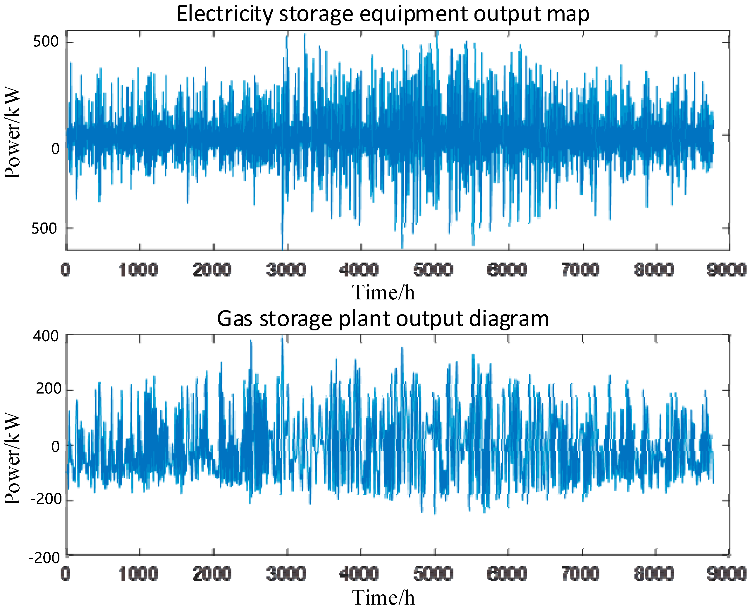
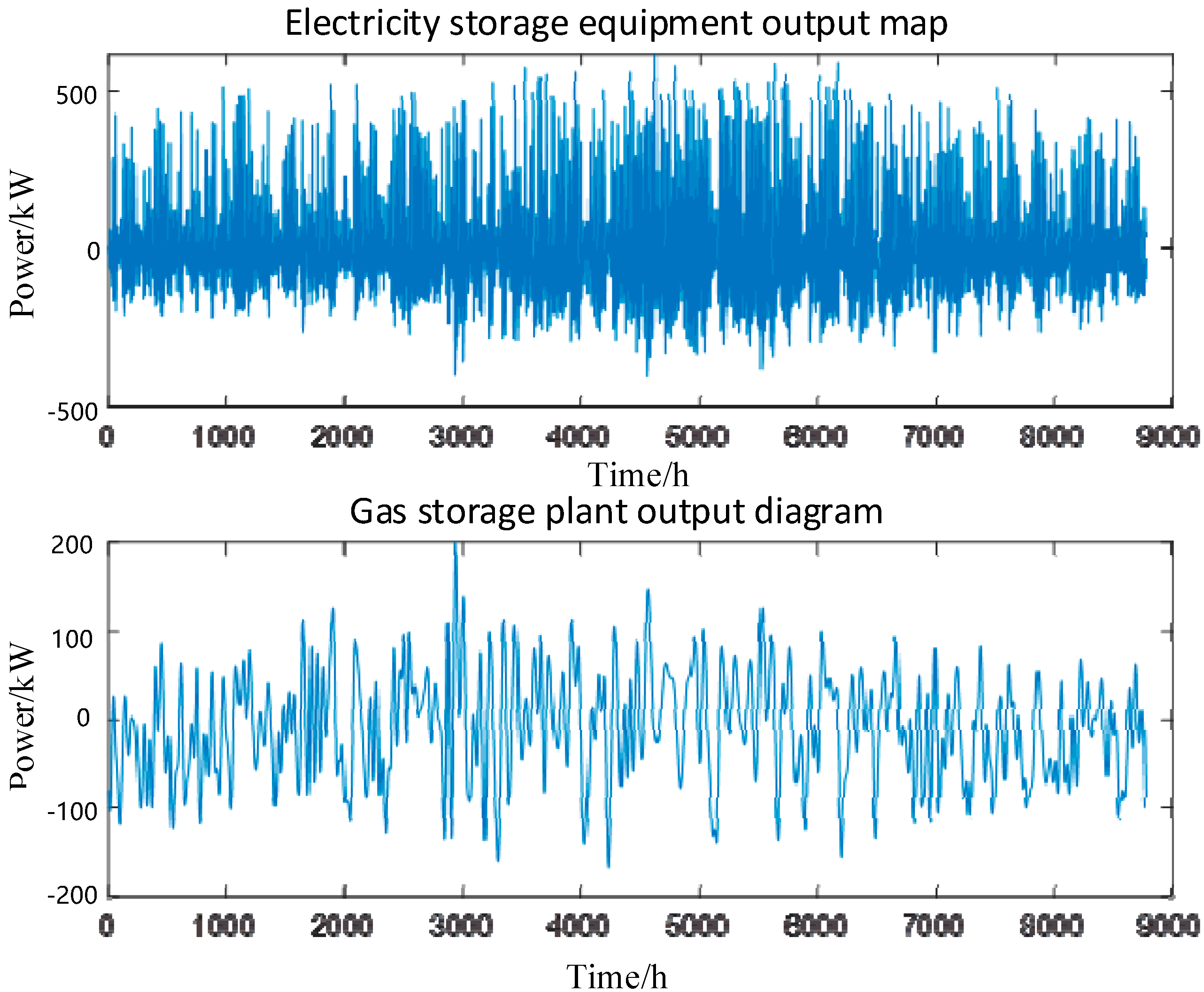
A comparison of the output of each energy storage device before and after optimization is shown in
Figure 19 and
Figure 20 below.
Comparing the power curves before and after optimization, it can be seen that the fluctuation value of the power of the gas storage equipment before optimization is more drastic. After optimization, by strengthening the complementary mechanism between electrochemical energy storage and gas energy storage and optimizing the division of labor between the two types of energy storage equipment, it can be seen from the above figure that the electric storage system takes on the high-frequency component of power fluctuations, and the output of the gas storage system mainly takes on the low-frequency component of power fluctuations, which reduces the period of high-load operation of the gas storage equipment and makes its output curve smoother. The optimization gives full play to the roles of two kinds of energy storage equipment, suppresses fluctuations in the output power of the whole system, makes the whole system run more smoothly, and prolongs the working life of the energy storage system.
An evaluation and analysis of the operation scenarios before and after optimization in terms of annual time scale and the results of economic cost, carbon emissions, and system energy efficiency are shown in
Figure 21. The optimization results of the different scenarios are shown in
Figure 21.
As can be seen in
Figure 21, after the optimization of the scheme, in terms of economy, the initial investment and annual investment volume increased to a certain extent due to the construction and commissioning of the gas system, but with the reduction in operation and maintenance costs, economy was significantly improved, and the annual profit was increased by CNY 3.78 million, with an enhancement of 22.96%. Environmental friendliness was significantly enhanced, and total annual carbon emissions were reduced by 7.44 t, with a reduction of 19.23%; however, the energy efficiency of the system decreased from 94.34% to 91.12%. This change is mainly due to the addition of the gas system, which results in more energy losses in the overall system due to the conversion and storage of gas energy, resulting in a slight decrease in system energy efficiency. Nonetheless, the environmental and economic benefits of the overall scheme were significantly improved, indicating that the introduction of the gas system still presents a major advantage in terms of overall system optimization.
5. Conclusions and Suggestions
The integrated energy system planning and optimization method based on hybrid energy storage proposed in this paper provides an innovative solution for the power allocation strategy of electric–gas hybrid energy storage systems by combining the grey wolf optimization algorithm with the adaptive noise integration empirical modal decomposition method. In this paper, the energy management strategy of an electric–gas energy storage system is discussed in depth, a management strategy optimized in line with the characteristics of alkaline electrolyzers and the operation characteristics of the energy storage system is proposed, and a multi-objective planning and optimization model of the integrated energy system is constructed. The following main research results and conclusions are obtained in this paper:
- (1)
In this paper, the grey wolf optimization (GWO) algorithm is combined with Integrated Complete Ensemble Empirical Mode Decomposition with Adaptive Noise (ICEMD with adaptive noise), which effectively improves the power allocation capability of the energy storage system. Compared to traditional decomposition methods, such as empirical mode decomposition (EMD) and Wavelet Packet Decomposition (WPD), the optimization method not only improves the flexibility and responsiveness of the power system under different loads and complex conditions, but also enhances the system’s adaptability to fluctuating loads and environmental changes, and provides a more fine-grained power allocation strategy for electric–gas energy storage systems.
- (2)
By addressing the unique operating characteristics of alkaline electrolyzers, a refined energy management strategy is proposed to optimize the energy management of the hybrid electric–gas energy storage system. Compared to previous standalone electrical energy storage or gaseous energy storage, this strategy significantly improves the system’s responsiveness during grid fluctuations and peak energy demand, improves the overall energy efficiency and utilization efficiency of the energy storage system, and provides effective technical support to cope with unstable power supply and demand fluctuations.
- (3)
A multi-objective programming optimization model for a multi-timescale integrated energy system based on hybrid energy storage is proposed. This paper comprehensively considers various forms of energy, such as electricity, heat, and gas, and introduces hybrid energy storage technology, taking into account economic, environmental protection, and reliability objectives, among others, in order to achieve the efficient use of energy, stable supply, and green transition. The model provides scientific decision-making support for the planning and optimization of energy systems and green transformation, and promotes sustainable development.
- (4)
The optimized system shows better stability and performance. The power fluctuations in the gas storage equipment are significantly reduced and the synergy between the power storage and gas storage equipment is maximized. After optimization, the power storage system mainly takes on high-frequency power fluctuations, while the gas storage system mainly responds to low-frequency fluctuations, which makes the output curve smooth and reduces the periods of high-load operation of the gas storage equipment. This not only improves the stability of the system, but also extends the service life of the energy storage system.
- (5)
Significant improvement in economy and environmental protection are witnessed. After the optimization of the scheme, there is a significant improvement in economy. Despite the increase in the initial investment of the gas system, with the reduction in operation and maintenance costs, the annual profit increased by CNY 3.78 million, an improvement of 22.96%. In terms of environmental friendliness, the optimized system significantly reduces carbon emissions, with annual carbon emissions reduced by 7.4 tons, an improvement of 19.23%. This shows that the optimized solution not only improves the economic efficiency of the system, but also plays an important role in promoting green transformation and reducing carbon emissions.
In summary, this paper not only provides theoretical support for the efficient operation of integrated energy systems through innovative optimization methods and refined energy management strategies, but also provides practical technical solutions to promote the green transformation of energy infrastructure and sustainable development. Research indicates that, compared to the advancements made by other researchers currently, the planning method for integrated electric–gas–heat energy systems based on long- and short-term energy storage coordination proposed in this paper achieves remarkable results in terms of enhancing system stability, economy, and environmental friendliness, and holds broad application prospects. The research results provide an important reference for the low-carbon, flexible, and efficient operation of future energy systems, and provide technical support and theoretical guidance for realizing the global green energy transition. Due to issues such as the length of this paper, there are certain limitations. Future researchers may consider adding energy storage devices such as flywheel energy storage and supercapacitor energy storage in addition to the aforementioned storage devices to conduct further research based on this paper.

