Abstract
Energy demand is rising over time in both developing and developed countries. Therefore, finding new sources of energy is a prime concern now. For this effort, this paper presents the pyrolysis of onion (Allium cepa) shells in a reactor with a fixed bed for generating alternative liquid fuel. This paper also compares alternative fuel characteristics, including higher heating value, viscosity, density, pour point, and flash point, with conventional petroleum fuels at optimal process conditions. The work adopted pyrolysis to produce liquid fuel at a temperature range of 400–550 °C and utilized LPG to provide a heat source. The liquid product (fuel oil) was collected, and non-condensable gas was flared. The liquid product was tested for various properties, and the results of the analyses show that alternative fuel has a higher heating value of 12.227 MJ/kg, density of 800 kg/m3, viscosity of 4.3 cP at 30 °C, pour point below −6.2 °C, and flash point around 137 °C, with a variation due to the volatile matters. To obtain favorable conditions for pyrolysis, some parameters, including bed temperature, sample quantity, average particle size, and operating time, were varied and analyzed. The physio-chemical properties made the alternative fuels isolated from conventional petroleum fuels due to the variation in distillation temperature. This work shows that the fuel oil generated from the pyrolysis of onion shells could be considered an alternative source of fuel.
1. Introduction
Fuel oil demand is increasing due to the increase in population throughout the world. On the contrary, the reserve of conventional fuels (diesel, petrol, gas, and so on) is declining day by day [1,2]. Consequently, social, environmental, economic, and ecological conditions also need to be considered when finding alternative fuel sources [3]. Different routes and technologies are available for liquid fuel generation, and finding new fuel sources is a significant effort. In these contexts, pyrolysis, fermentation, and transesterification are taken as the alternative methods for compensating the increased energy demand by managing biomass (such as domestic and industrial wastes) with a prime concern of environmental aspects [4]. Among these methods, pyrolysis is considered the most efficient and simple technique for fuel production [5]. Pyrolysis could be defined as the thermal disintegration of biomass and biomass-like products in an oxygen-free environment [6,7]. This technique was introduced around 2500 B.C. near the Middle East and Southern Europe for charcoal production. Additionally, using this method, tar was produced to seal the boats and preserve certain agents in ancient Egypt. From then on, this method has been widely growing and has gained huge popularity, especially for coke and charcoal production. The reasons behind this popularity are the capability of charcoal in terms of generating the melting temperature for bronze formation from copper and tin, the production of bio-fuel with relatively large amounts compared to the feed ratio [8]. This method could be used to produce higher-valued fuel oil, which can compete with conventional liquid fuels as an alternative clean fuel.
Numerous works have been carried out on pyrolysis throughout the decades. Earlier work of pyrolysis showed the reactions in pyrolysis stages and observed the product’s behavior due to the reaction conditions [9], production of char, liquid, and gas from four different wastes of cashew nutshell, sawdust, chicken litter, and sugarcane straw at different temperatures and pressure [4]. The results of their investigation proved that the production of alternative fuel from cashew nutshell, sawdust, and sugarcane straw reflects excellent potential [4]. Another work presented a mixture of different food wastes (including onion peel) to attain maximum biochar yields by varying reactor temperature, reaction time, and heating rate [10]. However, operating temperature has a forthright impact on the textural and structural characteristics of pyrolyzed products [11]. Their work showed that onion skin may shortly be a useful source for producing alternative fuel oil rather than considering it a waste. Another earlier work showed that the waste from onions can be utilized for electricity generation, which may pave a sustainable way to fulfill the energy demand [12]. Furthermore, they claimed that microbial fuel cells show better results than the other works regarding low internal resistance and high power density. Experimental work showed that pyrolysis is suitable for generating alternative fuels with a density near diesel, and the calorific value was half that of conventional petroleum fuels [13]. This can also be performed for bagasse as a raw material with 66% yield from bio-oil of pyrolyzed bagasse, and higher heating value (HHV) was about one-third of the conventional petroleum fuels [14]. Hence, utilizing onion shells is a prospective option that has not yet been extensively focused on in prior research. At the same time, using onion shells for fuel production could reduce environmental waste. Consequently, additional money needed for proper environmental waste and emission management would be reduced. Hence, this work focuses on generating useable liquid fuel from onion shells.
On the other hand, a huge amount of biomass is wasted in landfills during the processing of crops and incineration processes, which brings about serious environmental degradation and the waste of energy resources [15]. For this reason, biomass energy is nowadays considered a potential renewable source of energy [16]. Among those biomasses, onion shell is considered a potential that is generally available as waste in China, India, the United States, Egypt, and many other countries, and it is ploughed mostly in China, India, the United States, Bangladesh, Turkey, and some of the Middle East countries. In addition, many European countries like the United Kingdom, Spain, and others have been facing some environmental problems as they have produced over 500,000 tons of waste, including the outer dry brown skin of an onion [17]. Bangladesh has a yearly demand for onions of about 3.5 to 3.6 million tons for FY2021 [18]. In 2021, Bangladesh produced 3.36 million tons of onion, while the total import of onion stood at 0.55 million tons. A total of 4 million tons of onion with onion shells were available, while the demand was 2.62 million tons for the year 2020-21. Again, the statistics found from the Ministry of Agriculture exhibited that the country harvested about 3.45 million tons of onion in FY 2022-23. The Bangladesh Bureau of Statistics showed an overall onion (onion with onion shell) generation rate of 2.27 million tons per year for Bangladesh [18].
In this work, the onion shell was pyrolyzed with varying average particle sizes, temperatures, gas flows, and sample quantity to obtain the maximum quantity of liquid products. Further, this liquid fuel was tested using different instruments and techniques to determine its characteristics. Finally, the properties obtained from the tests were compared to conventional petroleum fuels to determine its potential as a sustainable alternative fuel.
2. Materials and Design of Pyrolysis System
Several instruments were used to construct the designed pyrolysis system, as shown in Figure 1. The reactor, shown in Figure 1a, is an enclosure where the feedstock material (onion shell) is pyrolyzed in an inert atmosphere. The reactor was surrounded by a biomass heater. The reactor gained heat from the biomass heater. Nitrogen (N2) gas was supplied inside the reactor to create an inert atmosphere. Furthermore, the processed onion shell was decomposed in the absence of O2. A condenser, which is actually a parallel flow heat exchanger used to cool down the hot gases coming from the reactor, is a hollow-shaped cylinder, as shown in Figure 1b, through which a small-diameter pipe was passed. The gas from the feed material flows through the pipe, while the water flows outside the pipe through the hollow cylinder. The hollow-shaped cylinder had two openings. One opening was attached to the upper portion, supplying the cold water, and another opening was at a lower portion, rejecting hot water from the condenser. The entire condenser remained cold by the continuous flow of water. The reactor temperature was recorded using a digital thermometer of the TM6801B model, Winston, Zhejiang, China, having a K-type thermocouple of nickel–alumel materials with a measurement range of up to 1300 °C, inserted through the top to the middle of the reactor, where the pyrolysis occurred. Proper sealing was performed so that the gas could not escape. Figure 1c shows a biomass heater, which is a cylindrical shape confinement. Two cylindrical shapes were attached by clamps to make the biomass heater. The inside hollow cylinder was made of a 24-grade mild steel sheet of 15 cm in diameter, and the outside hollow cylinder was made of an 18-grade mild steel sheet of 20 cm in diameter. Glass wool was used between the two cylinders to make it heat resistant. In this work, solid fuels, like briquettes (charcoal) and a wood powder mixture, were used as fuel to produce the heat required for pyrolysis.
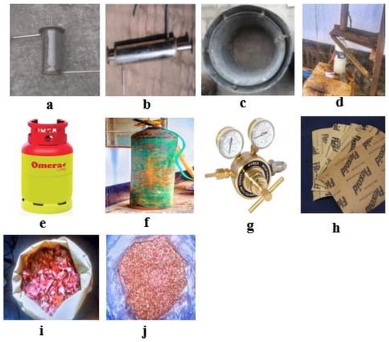
Figure 1.
Different parts of the fixed-bed pyrolysis setup; (a) Reactor; (b) Condenser; (c) Biomass heater; (d) Liquid collector; (e) LPG cylinder; (f) N2 gas cylinder; (g) MUREX 57 series gas flow meter; (h) Liquid gasket; (i) Onion shell; (j) Feed materials with average particles size of 200–300 µm.
Additionally, different types of water bottles, one of which is shown in Figure 1d, were used as liquid collectors. It was placed below the outside opening of the condenser, and the condensed liquid was collected, which flowed through the condenser and was derived from the reactor. A liquefied petroleum gas (LPG) cylinder, shown in Figure 1e, was used to provide the required heat during the pyrolysis of onion shells inside the reactor. This is because LPG fuel does not usually generate unburnt carbon, smoke, and other gases that are helpful for the human respiration system. LPG and natural gas are both clean-burning fuels, but LPG is more energy-efficient than natural gas. LPG is also more efficient than oil, wood, and electricity. On the other hand, it is cheap when compared to electric heat. Hence, this work used LPG as a heating source, considering energy-efficient sources and for a proper human respiration system with less environmental pollution. Considering the environmental impact of the life cycle assessment, LPG was used in the process. During the winter, when sunlight is not available for the drying process, an electric oven could be used as well, and it would not impact the environment. However, the major concern is the heating source that is provided via LPG, which has less impact on the environment. Hence, for the pyrolysis process, starting from the feedstock of onion shell to the end product of pyrolytic oil, it is feasible to maintain a clean environment throughout the life cycle of the pyrolysis process.
N2 gas cylinder was used, as shown in Figure 1f, to provide N2 gas in the reactor. The gas attains an inert atmosphere inside the reactor, as the process must have happened in the absence of O2.
A gas flow meter (MUREX 57, RICHU, Zhejiang, China), which has a capacity of 0–40 L/min and is shown in Figure 1g, was utilized to read and maintain the gas flow rate in the range of 4–10 L/min. Liquid gaskets, shown in Figure 1h, were used for airtight sealing of different flanges. Moreover, the onion shell (Figure 1i) was powdered using a crusher machine to an average particle size of 200–300 µm, as shown in Figure 1j. The vapor residence time (VRT) of the reactor was calculated from the equations below and the corresponding data.
The effective volume of the reactor was calculated using the inside diameter and height of the reactor, following Equation (1) as shown in Table 1, and it was found to be 2.254 × 10⁻³ m3. The volume (V) of the volatiles and gases generated from the pyrolysis was calculated at 0.4611 m3 using Equation (2), where P is the pressure inside the reactor, m is the mass, and T is the average operating temperature for volatile products and gases. By applying this value, the volatile and gas production rate can be calculated from Equation (3) for 5 min. Finally, the VRT calculated from Equation (4) for the reactor is 1.473 s.

Table 1.
Performance parameters used in this pyrolysis system.
The VRT indicates that it is a fast pyrolysis process [19,20]. Generally, in this process, vapors, aerosols, and charcoal are produced by the decomposition of biomass, and due to the cooling and condensation, a liquid of dark brown color is also generated that has a half heating value compared to conventional fuel [20].
The mass flow rate of gases (mg) and total heat flow rate (Q) were calculated as 0.00477 kg/s and 3360 J, respectively, utilizing Equation (5), where mw, Cw, Cg, tg1, tg2, tw1, and tw2 are water flow rate, water’s specific heat, gas’s specific heat, gas inlet temperature, gas outlet temperature, water inlet temperature, and water outlet temperature, respectively. Furthermore, the logarithmic mean temperature difference (∆Tm) can be calculated at 223.2 K, using the inlet temperature difference, ∆T1 = (tg1 − tw1), and outlet temperature difference, ∆T2 = (tg2 − tw2), as shown in Equation (6).
Using Equations (7) and (8), the effective condenser length and inner tube length were calculated as 29.95 cm and 49.91 cm, respectively, using the information of total heat flow (Q), overall heat transfer coefficient of stainless steel (U0), logarithmic mean temperature difference (∆Tm), the effective diameter of the condenser (DC), and inner tube diameter (dC).
3. Methodology
3.1. Pyrolysis Experiment
Figure 2 shows the schematic layout used for the pyrolysis process used in liquid oil generation from the onion shell. In the proximate analysis, it is found that the experimental onion shell contains 89% water, 4% sugar, 1% protein, and 0.1% fat. Experimental onions contained low energy (166 kJ per 100 g) and essential nutrients. Onion shells were collected from various sources, such as local bazaars and fields in Bangladesh, and prior literature shows that they usually contain crude protein of 3.06%, dietary fiber of 7.78%, crude fat of 1.08%, moisture of 8.08%, ash 5.93%, and total carbohydrates of 82.15% [21,22]. Dietary fiber helps to inhibit the absorption of water, which will eventually be helpful for the pyrolysis process. Onion shell powder contains low amounts of essential nutrients and fat and has an energy value of 215.88 to 220.32 kcal per 100 g [23]. To reduce the moisture, the shells were dried for up to 7 days to prepare for powdering and preserved for 2 days to cope with the room temperature. After drying, the water content decreased to about 1 to 2%, and, afterward, the shells were crushed using a crushing machine to produce powder, and the average particle size was maintained at about 200 to 300 µm. In this work, a pressure regulator of model MUREX 57 was utilized to regulate the pressure of N2 gas from the gas cylinder to the reactor. A digital thermometer with a thermocouple was used for measuring temperatures between 0 and 550 °C.

Figure 2.
Schematic view of the pyrolysis system.
The main equipment used for conversion was a reactor, as shown in Figure 2, in which the feed material was heated by an external heater that burnt the feed at the required temperature of about 400–550 °C. For this experiment, pyrolysis bed temperature, sample size, moisture content, and gas flow rate are the main parameters that need to be controlled to obtain a consistent quality of pyrolytic oil. Initially, starting with a lower temperature with a bigger size of onion shell, the generation volume of pyrolytic volume was quantified. After that, the average diameter was reduced by increasing the temperature of the reaction to achieve a high pyrolytic oil yield and optimize all the experimental parameters. Based on these pilot experiments, the final parameters for the bed temperature, sample quantity, average particle size, and operation time were identified for the final run of the experiment. By maintaining the same particle size, pyrolysis bed temperature, drying condition, and gas flow rate, the consistent quality and performance of the pyrolytic oil could be maintained. These optimized parameters were compared with a prior pyrolytic oil process that shows the optimized bed temperature in between 450 and 550 °C.
Two flanges were used to connect a pyrometer and a condenser with the reactor. A gasket was used in the middle of the flanges to make the joints airtight. Thread tape was used in every joint to connect more easily. An elbow of 2.54 cm in diameter was used to fill up the joint between the reactor and condenser. A biomass heater was used as the body shape, which holds the whole setup. An LPG gas cylinder was used to supply gas to the heater. A connection was made between the gas cylinder and the heater through a pipe. The flow of coolant and gas was controlled by regulating the control valves. Table 2 and Table 3 present the experimental operating parameters of the pyrolysis processes for the generation of liquid fuel from onion shells.

Table 2.
Operating parameters used in this pyrolysis system.

Table 3.
Typical operating parameters and products for the pyrolysis process [23].
Table 4 presents the sample quantities (200, 250, 380, and 300 g) with an average particle size of 250, 300, 200, and 250 µm, respectively, supplied in the reactor for burning for around 50 (2nd and 4th runs) and 80 min (1st and 3rd runs) during four different runs. The effect of sample quantity and average particle size on the reactor temperature clearly indicates that a sample quantity of 200 g with an average particle size of 250 µm has a higher rate of temperature increase in the reactor compared to a sample quantity of 380 g with an average particle size of 200 µm. The temperature rose in the 1st run (sample quantity of 200 g and an average particle size of 250 µm) from 28.9 to 500 °C, 42.12 to 525 °C for the 2nd run (sample quantity of 250 g and average particle size of 300 µm), 45 to 410 °C for the 3rd run (sample quantity of 380 g and average particle size of 200 µm), and 40 to 460 °C for the 4th run (sample quantity of 300 g and average particle size of 250 µm).

Table 4.
Different parameters used for the 1st, 2nd, 3rd, and 4th runs.
3.2. Experimental Products
In this work, a black-colored liquid was considered the primary product used as an alternative fuel after processing through different treatments. Conversely, gaseous and char-type products with high calorific value were termed secondary products. Both products can be used further as fuel for reactor heating, and, in addition, char has the potential as a feed material for creating higher-value activated carbon and soil fertilizer on the land [24,25]. Figure 3 shows the char and oil produced from the onion shell pyrolysis system.
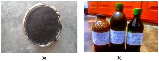
Figure 3.
(a) Produced char. (b) Produced oil from onion shell pyrolysis.
However, to measure the higher heating value of pyrolyzed oil using a bomb calorimeter, 1 g of oil was sampled and kept in an airtight chamber. Then, oxygen was supplied in that chamber for the complete combustion of oil. The bomb was kept in a water container. A Beckmann thermometer was attached to the chamber, and the temperature of the water was determined by burning 1 g of oil.
where m, M, s, and are the mass of water, the mass of oil, the specific heat of water, and the temperature difference of water, respectively.
4. Results and Discussion
A total of four experimental runs were carried out in this work. Those experiments differed from each other based on the sample quantity, average particle size, and time duration of pyrolysis. As the average particle size varied, the results varied significantly. The performance and liquid properties tests gave the research work a large amount of data that helped to compare pyrolysis oil with conventional fuels.
4.1. Effect of Feed Particles on Reactor Temperature
Figure 4 shows the correlation of pyrolysis time and reactor bed temperature for 200 g of 250 µm and 300 g of 200 µm sample quantities (1st and 3rd runs). As shown in Figure 4, the reactor temperature increases with time for both of these two samples. In addition, the temperature initially rises linearly, while this variation is not linear after 50 min run time. Figure 4 also shows that the temperature rise for 200 g of 250 µm sample is high when compared to 300 g of 200 µm. This indicates that the increase in reactor temperature depends on sample particle size. On the other hand, the total duration of the increase in temperature depends on the volume or quantity of samples.
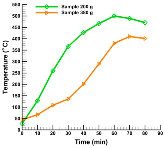
Figure 4.
Effect of sample quantity (200 g and 380 g) on reactor temperature.
Figure 5 presents the correlation of pyrolysis time and reactor bed temperature for 250 g of 300 µm and 300 g of 250 µm sample quantities (2nd and 4th runs). Moreover, the reactor temperature increases with time for both of these two samples. The temperature initially rises linearly up to 10 min run time, then rises sharply until 35 min. Figure 5 also presents that at the end of 35 min run time, the reactor bed temperature is equal for both samples at about 450 °C. After that, the reactor bed temperature starts to decrease.
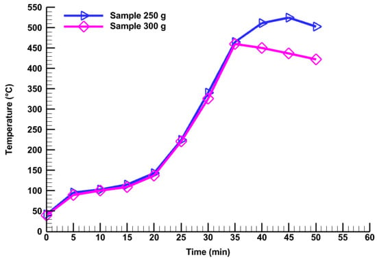
Figure 5.
Effect of sample quantity (250 g and 300 g) on reactor temperature.
Figure 6 shows the oil, gas, and char production at different temperatures, sample quantity, and sample size. Figure 6a presents the percentage of oil, gas, and char production at different temperatures. It is seen from Figure 6a that for a 200 g sample quantity and 250 µm average particle size, the maximum oil production is 45% at about 500 °C where the char generation is about 30%, and gas production is the lowest at about 24%. On the other hand, a maximum gas generation of about 44% and a minimum of 29% oil products are produced at 525 °C for a 250 g sample quantity and 300 µm average particle size, respectively, as shown in Table 5. Figure 6b shows the percentage of oil, gas, and char production at different sample quantities. It is clear from Figure 6b that the maximum liquid oil generation of about 45% is achieved for a 200 g sample quantity, whereas gas production is the lowest at around 24%. The same conclusion can be made for a sample size of 250 µm, as depicted in Figure 6c.
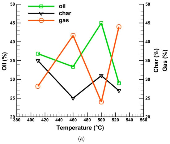
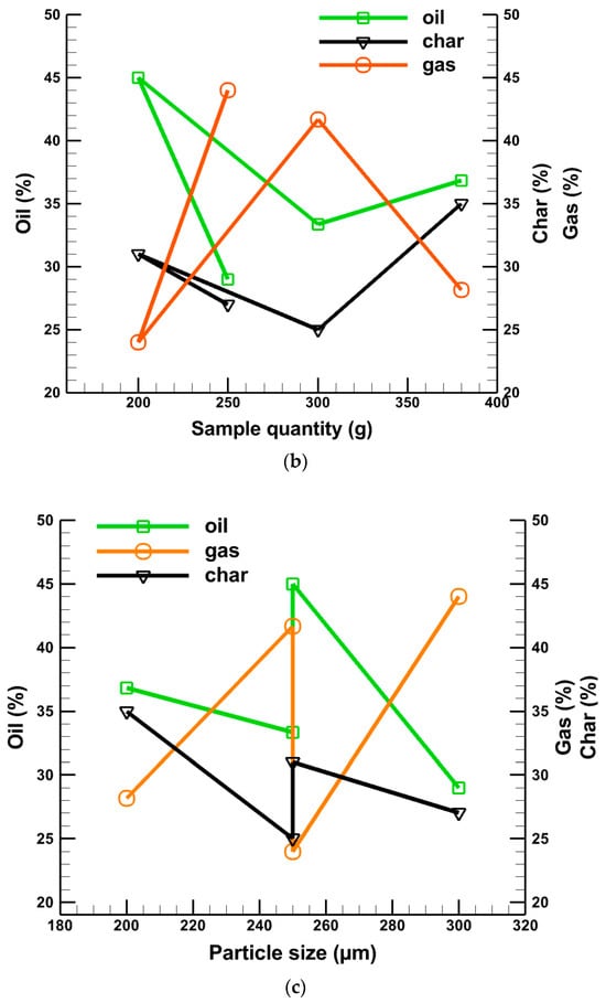
Figure 6.
Effects of (a) temperature, (b) sample quantity, and (c) average particle size on produced liquid oil, char, and gas.

Table 5.
Data for yield products (oil, char, and gas).
Combinedly, from Figure 6a–c, it is observed that a higher rate of oil production does not depend alone on the effect of temperature, sample quantity, and particle size. It has a combined effect that is accountable for the high percentage of oil production. From Figure 6, it can be summarized that a higher reactor temperature cannot provide a high percentage of oil alone. Similarly, smaller particle sizes and lower sample quantities cannot supply a higher amount of oil alone. The higher reactor temperature and smaller particle size with a lower sample quantity can produce a higher percentage of oil with a minimum percentage of gas. All these data are summarized in Table 4.
4.2. Properties of Pyrolysis Oil
Fuel has various properties, including viscosity, density, specific gravity, calorific value, pour point, flash point, fire point, pH value, and chemical compositions. In this research work, viscosity, density, flash point, pour point, and higher heating value were measured for the produced pyrolyzed oils. The higher calorific values are found at 12.227 MJ/kg. To determine the density, a weight balance and measuring cylinder were used, and the mass of the cylinder was measured by the balance. The density of the product was found to be 800 kg/m3. The viscosity of the onion shell oil was found to be 4.3 cP at 30 °C, as shown in Table 6. The viscosity of onion shell oil was measured by the “RION VISCOTESTER VT-03F, Mainland, China”. Using a flash point tester, the flash point of pyrolyzed oil was found to be around 137 °C. A little bit of variation was observed due to the volatile matter that contaminated the liquid oil.

Table 6.
Physical characteristics of produced liquid fuels from pyrolysis of onion shell.
To find out the pour point of the pyrolyzed liquid oil, ice was placed in a jar. Then, 10 cc of onion shell oil was taken in a pot surrounded by ice. A thermometer was placed into the pot to measure the temperature fall until the oil became thicker. The pour point of the pyrolysis oil was found below −6.2 °C.
4.3. Comparison of Onion Shell Oil with Conventional Petroleum Fuels
According to Lu et al. [26], bio-oils generated from biomass are low-grade liquid fuels compared to petroleum fuels. Different phenomena such as higher levels of O2 and H2O contained in biomass, higher tendency of surface tension, viscosity and lower level of pH values, heating values, ignition of liquid obtained from pyrolysis, higher complex multiphase structures including solids and ash with chemical and thermal instability, and combustion properties made it difficult for commercialization. Despite these poor fuel properties, lubricity, less toxicity, more biodegradability, lower processing cost, and high liquid oil production potential made it more promising than petroleum fuels. In addition, although the HHV of liquid oil is typically lower, its density is slightly higher than that of conventional petroleum fuels. The HHV of pyrolyzed onion shell oil is 12.227 MJ/kg, almost one-fourth of petroleum fuels, as shown in Table 7.
Consequently, density (800 kg/m3) is recognizably higher than gasoline fuels but slightly lower than diesel and light fuel oil (LFO). This indicates that onion shell oil could store or transport more energy than gasoline but less than diesel for the same fuel volume. In terms of viscosity, produced oil has 4.3 cP, higher than gasoline and diesel fuels but much lower than heavy and light fuel oil. This suggests that onion shell pyrolysis oil provides lower engine performance than diesel and gasoline but better than heavy and light fuel oil because of the increase in friction and loss of energy. The flash point is an important property of fuels in handling it to prevent fire hazard, which usually varies from 40 to 70 °C or above 100 °C for bio-oils depending on the organic volatiles [27]. Table 7 clearly shows that the flash point of produced oil is 137 °C, much higher than gasoline, diesel, and LFO. Hence, this pyrolytic oil is safe to use and could prevent fire hazards. In the usual case, the pour point of bio-oil produced from different woods lay between −12 and −33 °C, but other materials may go beyond this range [26]. The pour point of onion shell oil is less than −6.2 °C, which is comparatively higher than that of petroleum fuels. This also indicates the suitability of the onion shell pyrolytic oil as lower pour fuel is usually desirable.

Table 7.
Comparison of onion shell oil with conventional petroleum fuels.
Table 7.
Comparison of onion shell oil with conventional petroleum fuels.
| Analysis | Onion Shell Oil | Diesel [28,29,30] | HFO [30,31,32] | Gasoline [32,33,34,35,36] | LFO [30,31,32,33] |
|---|---|---|---|---|---|
| Viscosity (cP) at 30 °C | 4.3 | 2.1 | 21 | 1.7–1.95 | 30 |
| Density (kg/m3) | 800 | 840 | 980 | 719.7 | 830 |
| Flashpoint (°C) | 137 | 55 | 110 | −40 | 79 |
| Pour point (°C) | <−6.2 | −33 | −18 | - | −15 |
| HHV (MJ/kg) | 12.227 | 45.9 | 44.16 | 47.3 | 44.97 |
4.4. Cost Analysis
The cost of consumable products, including onions and LPG gas, changes over time, as well as other factors. However, in this study, the estimated costs for the pyrolysis process from raw material to the end product are fixed, and their estimated values are shown in Table 8.

Table 8.
Cost analysis of different materials of pyrolysis process.
5. Future Recommendations for Using Pyrolyzed Products
Different products that were provenanced from the pyrolysis of onion shells may be used in different fields after modification through different methods. According to Zhang et al. [37], reduction of O2 from the pyrolyzed oil through upgrading is necessary before it is used in any systems or processes to generate power. They also mentioned some upgrading techniques, including hydrodeoxygenation, reforming of steam, emulsification, and chemical extraction. It is seen from the fuel characteristics of pyrolytic oil generated from onion shells that these fuels show higher density than gasoline and lower viscosity than heavy and light fuel oil. Hence, after upgrading the onion shell pyrolytic oil, it can be used in small vehicle engines to replace gasoline and heavy and light fuel oil. This fuel could also be used as a bio-gasoline fuel with pure gasoline. Even in some cases, this fuel could be used to produce biodiesel fuel with pure diesel to reduce the pressure on conventional diesel, gasoline, and heavy and light fuel oil. Hence, the future plan would be to use them in small vehicles like auto rickshaws and petrol engines and run other small engines to quantify engine performance and efficiency.
Many different processes are available to upgrade the pyrolytic oil, including hydrodeoxygenation, steam reforming, and catalytic cracking. They are expensive and highly complex, and they require a modern reactor. The amalgamation of different agents can remarkably alternate the properties of pyrolyzed oils. A test was conducted through the blending of methanol in a certain percentage with the pyrolyzed oils by Boucher et al. [38] to utilize the blend as a fuel by analyzing the performance of a gas turbine. They observed that although viscosity and density decreased, the stability increased in the blended fuels with compensation of lower flash points. Furthermore, the liquid product can be used for hydrogen production, as shown in Figure 7.
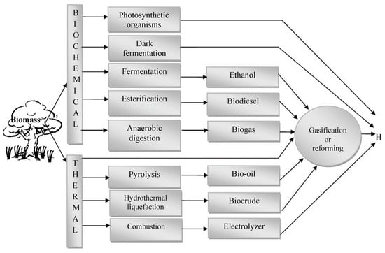
Figure 7.
Routes by which hydrogen can be produced from biomass [39].
The major challenge and limitation associated with scaling up the pyrolytic process from the laboratory to industrial production is the amount of yield oil generation per batch. On the laboratory scale, it is possible to produce a small volume of oil by consuming the lower volume of onion shell with a low gas flow rate. On the other hand, at the industry level, it is important to maintain the high volume of pyrolytic oil; otherwise, the overall production cost will increase, eventually raising the pyrolytic fuel cost even when compared to conventional fuels, including diesel, petrol, and natural gas. Additionally, the extracted pyrolytic oil from onion shell cannot be used directly as fuel as it needs to be upgraded, which could increase the fuel cost at the industry level. A large land area is also needed to make this industry feasible, which is rare now, especially in developing countries like Bangladesh. The open land area would be suitable for collecting and processing the raw onion shells, drying them, and making them particles using the crushing system. Lastly, skilled human resources are needed at the industry level to process the raw material to produce a high yield of pyrolytic oil.
6. Conclusions
This work implies the following conclusions:
- Pyrolytic oils have been produced from the onion shells through fast pyrolysis, where fuel density is higher than gasoline. The viscosity of the generated pyrolytic oil is higher than diesel but lower than heavy and light fuel oil. In summary, the properties of pyrolyzed liquid oils like density, viscosity, pour point, and flash point were found to be 800 kg/m3, 4.3 cP, less than −6.2 °C, and 137 °C, respectively.
- Using the fixed-bed pyrolysis of the onion shell, the maximum amount of liquid fuel was found to be 45% at 500 °C reactor bed temperature, 250 µm average particle size, and 200 g sample quantity for pyrolysis time of around 80 min. Higher percentages of gas and tar were produced in liquid products due to the secondary reactions, as the temperature and residence time were comparatively larger.
- Generated pyrolytic oils showed a higher calorific value of about 12.227 MJ/kg, much lower than those of different biomass-acquired fuels. By adding additives, the oil could be more efficient than other conventional and biomass-derived fuels.
Author Contributions
All the authors of this research have contributed significantly to the work submitted. Conceptualization, M.A.H.; original draft writing and preparation, M.A.H. and F.R.; review and editing, F.R., M.A.H., M.E.H., M.A. and M.S.A. All authors have read and agreed to the published version of the manuscript.
Funding
This research received no external funding.
Data Availability Statement
The original contributions presented in the study are included in the article, further inquiries can be directed to the corresponding authors.
Acknowledgments
The author would like to acknowledge the infrastructural support provided by the Department of Mechanical Engineering, Rajshahi University of Engineering & Technology, Bangladesh.
Conflicts of Interest
The authors declare no conflicts of interest.
Nomenclature
| VRT | Vapor residence time | SRT | Solid residence time |
| HHV | Higher heating value | HFO | Heavy fuel oil |
| LFO | Light fuel oil | ||
| LPG | Liquefied petroleum gas |
References
- Sharma, P.; Bano, A.; Singh, S.P.; Atkinson, J.D.; Lam, S.S.; Iqbal, H.M.; Tong, Y.W. Biotransformation of food waste into biogas and hydrogen fuel—A review. Int. J. Hydrogen Energy 2024, 52, 46–60. [Google Scholar] [CrossRef]
- Wang, J.; Shan, Y.; Cui, C.; Zhao, C.; Meng, J.; Wang, S. Investigating the fast energy-related carbon emissions growth in African countries and its drivers. Appl. Energy 2024, 357, 122494. [Google Scholar] [CrossRef]
- Bhan, C.; Verma, L.; Singh, J. Alternative fuels for sustainable development. In Environmental Concerns and Sustainable Development: Volume 1: Air, Water and Energy Resources; Springer: Berlin/Heidelberg, Germany, 2020; pp. 317–331. [Google Scholar]
- Kimura, L.M.; Santos, L.C.; Vieira, P.F.; Parreira, P.M.; Henrique, H.M. Biomass pyrolysis: Use of some agricultural wastes for alternative fuel production. In Materials Science Forum; Trans Tech Publications Ltd.: Zurich, Switzerland, 2010; Volume 660, pp. 259–264. [Google Scholar]
- Benk, A.; Coban, A. A simple method for the production of fuel and fuel additives from renewable low-viscosity mineral oils (Number-10 oil) and their mixtures. Renew. Energy 2020, 147, 1491–1499. [Google Scholar] [CrossRef]
- Stauffer, E.; Dolan, J.A.; Newman, R. Chemistry and physics of fire and liquid fuels. In Fire Debris Analysis; Academic Press: Cambridge, MA, USA, 2008; pp. 85–129. [Google Scholar]
- Divine, D.C.; Hubert, S.; Epelle, E.I.; Ojo, A.U.; Adeleke, A.A.; Ogbaga, C.C.; Okolie, J.A. Enhancing biomass Pyrolysis: Predictive insights from process simulation integrated with interpretable Machine learning models. Fuel 2024, 366, 131346. [Google Scholar] [CrossRef]
- Jahirul, M.I.; Rasul, M.G.; Chowdhury, A.A.; Ashwath, N. Biofuels production through biomass pyrolysis—A technological review. Energies 2012, 5, 4952–5001. [Google Scholar] [CrossRef]
- Zaman, C.Z.; Pal, K.; Yehye, W.A.; Sagadevan, S.; Shah, S.T.; Adebisi, G.A.; Johan, R.B. Pyrolysis: A sustainable way to generate energy from waste. Pyrolysis 2017, 1, 3–36. [Google Scholar]
- Patra, B.R. Slow Pyrolysis of Agro-Food Waste to Produce Biochar and Activated Carbon for Adsorption of Pollutants from Model Wastewater. Ph.D. Thesis, University of Saskatchewan, Saskatoon, SK, Canada, 2021. [Google Scholar]
- Alonso-Lemus, I.L.; Escobar-Morales, B.; Lardizabal-Gutierrez, D.; de la Torre-Saenz, L.; Quintana-Owen, P.; Rodriguez-Varela, F.J. Onion skin waste-derived biocarbon as alternative non-noble metal electrocatalyst towards ORR in alkaline media. Int. J. Hydrogen Energy 2019, 44, 12409–12414. [Google Scholar] [CrossRef]
- Segundo, R.F.; De La Cruz-Noriega, M.; Milly Otiniano, N.; Benites, S.M.; Esparza, M.; Nazario-Naveda, R. Use of onion waste as fuel for the generation of bioelectricity. Molecules 2022, 27, 625. [Google Scholar] [CrossRef]
- Uddin, M.S.; Joardder MU, H.; Islam, M.N. Design and construction of fixed bed pyrolysis system and plum seed pyrolysis for bio-oil production. Int. J. Adv. Renew. Energy Res. 2012, 7, 405–409. [Google Scholar]
- Asadullah, M.; Rahman, M.A.; Ali, M.M.; Rahman, M.S.; Motin, M.A.; Sultan, M.B.; Alam, M.R. Production of bio-oil from fixed bed pyrolysis of bagasse. Fuel 2007, 86, 2514–2520. [Google Scholar] [CrossRef]
- Caglar, A.; Aydinli, B. The pyrolysis of industrial alliaceous plant wastes: Illustration of process and characterization of products. Energy Explor. Exploit. 2018, 36, 1692–1707. [Google Scholar] [CrossRef]
- McKendry, P. Energy production from biomass (part 1): Overview of biomass. Bioresour. Technol. 2002, 83, 37–46. [Google Scholar] [CrossRef] [PubMed]
- Vojvodić Cebin, A.; Šeremet, D.; Mandura, A.; Martinić, A.; Komes, D. Onion solid waste as a potential source of functional food ingredients. Eng. Power Bull. Croat. Acad. Eng. 2020, 15, 7–13. [Google Scholar]
- Available online: https://today.thefinancialexpress.com.bd/editorial/onion-ruckus-and-a-hole-in-statistics-1702563542 (accessed on 10 February 2024).
- Lede, J. Solar thermochemical conversion of biomass. Sol. Energy 1999, 65, 3–13. [Google Scholar] [CrossRef]
- Bridgwater, T. Biomass for energy. J. Sci. Food Agric. 2006, 86, 1755–1768. [Google Scholar] [CrossRef]
- Michalak-Majewska, M.; Teterycz, D.; Muszyński, S.; Radzki, W.; Sykut-Domańska, E. Influence of onion skin powder on nutritional and quality attributes of wheat pasta. PLoS ONE 2020, 15, e0227942. [Google Scholar] [CrossRef]
- Sayed, H.S.; Hassan, N.M.; El, M.H.A. The effect of using onion skin powder as a source of dietary fiber and antioxidants on properties of dried and fried noodles. Curr. Sci. Int 2014, 3, 468–475. [Google Scholar]
- Singh, J.; Gu, S. Biomass conversion to energy in India—A critique. Renew. Sustain. Energy Rev. 2010, 14, 1367–1378. [Google Scholar] [CrossRef]
- Buah, W.K.; Cunliffe, A.M.; Williams, P.T. Characterization of products from the pyrolysis of municipal solid waste. Process Saf. Environ. Prot. 2007, 85, 450–457. [Google Scholar] [CrossRef]
- Stančin, H.; Mikulčić, H.; Wang, X.; Duić, N. A review on alternative fuels in future energy system. Renew. Sustain. Energy Rev. 2020, 128, 109927. [Google Scholar] [CrossRef]
- Lu, Q.; Li, W.Z.; Zhu, X.F. Overview of fuel properties of biomass fast pyrolysis oils. Energy Convers. Manag. 2009, 50, 1376–1383. [Google Scholar] [CrossRef]
- Oasmaa, A.; Leppämäki, E.; Koponen, P.; Levander, J.; Tapola, E. Physical characterization of biomass-based pyrolysis liquids. In Application of Standard Fuel Oil Analyses; Technical Research Centre of Finland: Espoo, Finland, 1997. [Google Scholar]
- Goering, C.E.; Schwab, A.W.; Daugherty, M.J.; Pryde, E.H.; Heakin, A.J. Fuel properties of eleven vegetable oils. Trans. ASAE 1982, 25, 1472–1477. [Google Scholar] [CrossRef]
- McCarthy, P.; Rasul, M.G.; Moazzem, S. Analysis and comparison of performance and emissions of an internal combustion engine fuelled with petroleum diesel and different bio-diesels. Fuel 2011, 90, 2147–2157. [Google Scholar] [CrossRef]
- Yuliansyah, A.T.; Prasetya, A.; Ramadhan, M.A.; Laksono, R. Pyrolysis of plastic waste to produce pyrolytic oil as an alternative fuel. Int. J. Technol. 2015, 7, 1076–1083. [Google Scholar] [CrossRef]
- Tariq, A.I.; Saleh, A.M. An experimental investigation into the combustion properties, performance, emissions, and cost reduction of using heavy and light fuel oils. Case Stud. Therm. Eng. 2023, 44, 102832. [Google Scholar] [CrossRef]
- Mohan, D.; Pittman Jr, C.U.; Steele, P.H. Pyrolysis of wood/biomass for bio-oil: A critical review. Energy Fuels 2006, 20, 848–889. [Google Scholar] [CrossRef]
- Karkush, M.O.; Abdulkareem, M.S. Impacts of petroleum fuel oil contamination on the geotechnical properties of fine-grained soils. Indian J. Eng. 2018, 15, 228–237. [Google Scholar]
- Noor, M.M.; Wandel, A.P.; Yusaf, T. The development of MILD combustion open burner experimental setup. In Proceedings of the 2nd International Conference of Mechanical Engineering Research (ICMER 2013), Pahang, Malaysia, 1–4 July 2013; University of Southern Queensland: Toowoomba, Australia, 2013. [Google Scholar]
- Qi, D.H.; Lee, C.F. Combustion and emissions behaviour for ethanol–gasoline-blended fuels in a multipoint electronic fuel injection engine. Int. J. Sustain. Energy 2016, 35, 323–338. [Google Scholar] [CrossRef]
- Wijayanti, W.; Sasongko, M.N. Influence of sweet orange peel oil additive on physicochemical properties of gasoline. Alex. Eng. J. 2022, 61, 4875–4888. [Google Scholar]
- Zhang, Q.; Chang, J.; Wang, T.; Xu, Y. Review of biomass pyrolysis oil properties and upgrading research. Energy Convers. Manag. 2007, 48, 87–92. [Google Scholar] [CrossRef]
- Boucher, M.E.; Chaala, A.; Roy, C. Bio-oils obtained by vacuum pyrolysis of softwood bark as a liquid fuel for gas turbines. Part I: Properties of bio-oil and its blends with methanol and a pyrolytic aqueous phase. Biomass Bioenergy 2000, 19, 337–350. [Google Scholar]
- Muradov, N.Z.; Veziroğlu, T.N. “Green” path from fossil-based to hydrogen economy: An overview of carbon-neutral technologies. Int. J. Hydrogen Energy 2008, 33, 6804–6839. [Google Scholar] [CrossRef]
Disclaimer/Publisher’s Note: The statements, opinions and data contained in all publications are solely those of the individual author(s) and contributor(s) and not of MDPI and/or the editor(s). MDPI and/or the editor(s) disclaim responsibility for any injury to people or property resulting from any ideas, methods, instructions or products referred to in the content. |
© 2024 by the authors. Licensee MDPI, Basel, Switzerland. This article is an open access article distributed under the terms and conditions of the Creative Commons Attribution (CC BY) license (https://creativecommons.org/licenses/by/4.0/).