Article

Coupling Mechanism of Multiple-Thermal-Fluid Multi-Cycle Stimulation in Ultra-Heavy-Oil Reservoirs

Research Institute of Petroleum Exploration and Development (RIPED), Beijing 100083, China
*
Author to whom correspondence should be addressed.
Energies 2024, 17(9), 2129; https://doi.org/10.3390/en17092129
Submission received: 23 February 2024 / Revised: 12 April 2024 / Accepted: 18 April 2024 / Published: 29 April 2024
(This article belongs to the Special Issue Advances of Heavy Oil Recovery Technologies with Low Carbon-Intensity)

Abstract

:
Multiple-thermal-fluid (MTF) stimulation technology has been successfully applied in heavy-oil reservoir development, resulting in the significant enhancement of oil production. However, the underlying mechanism of multi-component coupling remains unclear. This paper constructs a coupling model for MTF stimulation, investigates the coupling mechanism of different media in various zones during multiple-cycle stimulation operations, and compares the implementation effect with field results. The findings reveal that (1) based on media distribution, the area from near-wellbore to far well locations can be divided into four zones: high-temperature oil-viscosity-reduction zones, compound action zones, energy-replenishment zones, and unaffected zones. (2) In the high-temperature oil-viscosity-reduction zone, the latent heat of vaporization is released by steam, and ultra-heavy oil absorbs heat and reduces its viscosity, which plays a dominant role in the production of MTF. In the compound action zone, hot water, CO2, and N2 exhibit a synergistic effect which enhances overall performance. In the energy-replenishment zone, a small amount of N2 provides pressure maintenance and an additional energy supply. (3) As more cycles of stimulation are conducted, the compound action zone expands, while the energy-replenishment zone contracts. Simultaneously, there is a decrease in contribution rate from the high-temperature viscosity-reduction zone to oil production but an increase from both the compound action zone and energy-replenishment zone up to 30%. Based on the dynamic law of representative wells, this paper proposes a multi-media zonal coupling mechanism, providing a reference for subsequent research on MTF stimulation mechanisms and the adjustment of production measures.

1. Introduction

Heavy-oil reservoirs are widely distributed in China. In the early 21st century, MTF technology has been widely used in offshore heavy-oil development due to its low cost, high space utilization rate, environmental friendliness, and low carbon advantages [1,2,3,4,5,6,7].
During steam stimulation, ultra-heavy oil is mainly heated by high-temperature steam to achieve viscosity reduction. In a reservoir, the flow capacity of steam is poor, and steam condenses quickly after injection. The heating time is short, the heating zone is small, and the heat utilization efficiency is low; therefore, the output of steam stimulation is low and the stable production time is short [7]. After converting to MTF stimulation, the oil production and wellbore-bottom flow pressure increase greatly, the water content decrease, and the production effect is improved. Non-condensate gas assists steam in heating reservoirs. On the one hand, non-condensate gas will hinder steam condensation. On the other hand, nitrogen’s low density and low thermal conductivity can reduce the heat loss of steam and improve the thermal efficiency of steam, improving its viscosity-reduction effect and inhibiting steam overlap [8,9,10]. After heating, the heavy components of ultra-heavy oil are cracked into light components, and the viscosity of ultra-heavy oil further decreases [11,12].
N2 is an almost insoluble element in heavy oil, but it has good diffusivity, recovering the reservoir pressure and providing additional drive energy while suppressing steam overlap [13,14]. After CO2 is injected into a reservoir, a portion of the CO2 is dissolved into ultra-heavy oil to reduce its viscosity and improve the oil–water flow ratio. After the pressure is reduced, a portion of the CO2 precipitates from ultra-heavy oil, forming dispersed small bubbles to form foam oil, which improves the flow capacity of heavy oil and contributes to carbon reutilization [11]. During this process, a portion of CO2 can be permanently stored in the formation to achieve carbon storage. At present, MTF stimulation is mainly applied to horizontal wells in medium and deep heavy-oil reservoirs offshore, while MTF is rarely applied to shallow ultra-heavy-oil reservoirs onshore. In MTF stimulation, there are thermodynamically stable mole and volume evolution and equilibrium phase compositions [15].
M oilfield is located in the eastern slope of the Caspian Basin in Kazakhstan. It is a shallow buried reservoir with relatively developed fluvial deposits. It is vertically divided into two oil layers, and it is a shallow, onshore, ultra-heavy oil, sandstone reservoir. The oil field was developed and put into production by steam stimulation in 2014, and the initial oil production of a single well was good, reaching 9–15 t/d. With the increase in steam stimulation cycles, M reservoir faced problems such as low production, rising water cuts, and falling formation pressure in the later stage.
Since 2018, field pilot experiments of MTF stimulation have been carried out in this block. The effect of MTF stimulation is exciting. After switching to MTF stimulation, periodic oil production was greatly increased, the stable production period was prolonged, water cuts were reduced, and bottom-hole flow pressure increased.
So far, research on the mechanism of MTF has only focused on the mechanism of a single medium, without considering the coupling mechanism of different media and the change in the mechanism in the multi-cycle process. This paper mainly takes M-4, a typical horizon well in M reservoir, as an example. Based on the clear geological and production law of the field, and combined with the production dynamic analysis of an MTF stimulation well, a MTF stimulation complex action model is established, focusing on the zonal coupling mechanism of different media of MTF in multi-cycle stimulation, which provides a theoretical basis for the further application of MTF stimulation in heavy-oil reservoirs.

2. MTF Stimulation Production Law

In M oil reservoir, the effect of steam stimulation becomes worse and worse after multiple cycles. Under these circumstances, MTF stimulation was introduced into this oilfield. The main equipment used for MTF include heat injection equipment, a water treatment system, nitrogen production equipment, nitrogen pipelines, and MTF pipelines. The MTF generator uses the combustion injection mechanism of a space rocket engine, and the pressurization equipment injects fuel diesel, light crude oil, or natural gas; high-pressure air; and softened water into the combustion chamber in a certain proportion. The heat generated by fuel combustion will turn most of the water into water steam. Finally, a high-pressure thermal fluid is formed by mixing steam and flue gas (mainly composed of N2 and CO2). The mass fraction of steam accounts for 70~80%, and the mass fraction of N2 and CO2 accounts for 15~25% and 5~15%, respectively. During the injection of MTF, an anti-corrosion agent will be injected into the oil well to prevent corrosion of the wellbore at the same time.
The pilot experiment of the further efficient development of shallow ultra-heavy oil reservoirs was carried out through integrated geological engineering technology. MTF stimulation was implemented in a total of 36 vertical wells. The M-4 horizontal well is located in the north of M reservoir. The vertical depth of the well is 370 m, the thickness of the oil layer is 15–25 m, and the length of the production well is 108.5 m. The crude oil viscosity under the formation conditions is 14,780.85 mPa·s, and the original formation temperature is 15 °C. As shown in Table 1, the M-4 well was put into production in 2014, and after five cycles of steam stimulation, it was switched to MTF stimulation in 2018. So far, it has carried out a total of three cycles of MTF.

2.1. Variation Law of Daily Oil Production

As shown in Table 1 and Figure 1(1), the daily oil production of the first five steam stimulation cycles is mostly 0–10 t/d, the average cycle production time is 279 d, and the cumulative oil production is 2504 t. After the shift to MTF stimulation, the daily oil production is increased to 10–25 t/d, and the average cycle production time is 571 d. The cumulative oil production of the three cycles is 12,675.3 t. Compared with steam stimulation, the accumulated oil production of MTF is increased by 5.1 times, and the average oil–steam ratio is increased by 11.44 times, ensuring environmental and economic benefits and efficient development at the same time.
In the three MTF throughput cycles, the second cycle of the MTF throughput cycle has the highest production capacity, with cyclic oil production of 4328.1 t and an oil–steam ratio of 2.997. With the increase in the stimulation period, the stimulation effect of MTF gradually decreases, and the steam injection amount increases to 4025 t in the eighth cycle; the cumulative oil production in the cycle is 4513.0 t, and the oil–steam ratio is only 1.121. The MTF throughput causes higher oil production and a longer stable production period in the early stage. The cyclic productivity can be maintained by increasing the steam and non-condensate gas injection volume, and this highlights a direction for the optimization of future production measures.
According to the production dynamic law analysis of M-4 well in M oilfield, after converting from steam stimulation to MTF stimulation, the daily oil production and bottom-hole flow pressure increases significantly, while the water content decreases significantly.

2.2. Variation Law of Water Content

As shown in Figure 1(2), the steam stimulation water content is mainly 70~100%, while the MTF stimulation water content is primarily concentrated at 40~80%. This shows that MTF stimulation can greatly reduce water content. In the early stage of an MTF stimulation, N2 and CO2 in the gas phase have a thermal insulation effect and can inhibit steam condensation. A part of the non-condensate gas can form bubbles to block the large pores in the formation due to the Jamin effect, inhibiting the production of formation water. After a period of production, the formation pressure drops, the bubble gradually bursts, and non-condensate gas is produced from the formation, resulting in the rise in water content 80% to 100%. From the sixth cycle to the eighth cycle, the cumulative time with the water content of 40~80% accounts for 85~90% of the total production time, and the water content remains stable and does not change significantly with the throughput cycle.

2.3. Formation Pressure Variation Law

M is a shallow ultra-heavy-oil reservoir, and its original formation pressure was only 2.56 MPa. As shown in Figure 1, the steam injected in the steam stimulation stage cannot replenish formation energy. As the stimulation period increases, formation pressure continues to decrease, and while its bottom-hole flow pressure remains stable in the early stage, it decreases rapidly in the later stage and drops to 0.5 MPa in the third cycle. A large amount of MTF non-condensate gas is injected into the formation, effectively supplementing the formation energy, raising the formation liquid supply level and increasing the bottom-hole flow pressure to 1.5~2 MPa. During the steam stimulation stage, the bottom-hole flow pressure decreased rapidly after 4 years of steam stimulation, while during the MTF stimulation for 4 years, the bottom-hole flow pressure remained at a high level (>1.5 MPa) and rose slightly at the end of the seventh and eighth cycles, indicating that the non-condensate gases, N2 and CO2, were partially stored in the formation.

3. Multi-Cycle MTF Stimulation Multi-Media Coupling Mechanism

MTF injection medium is composed of N2, CO2, and steam. The three different media influence each other, and the different mechanisms are coupled with each other. The MTF coupling mechanism is far more complex than that of a single medium. The existing single-medium mechanism cannot explain the change in the production performance of the M-4 well in multiple cycles. Therefore, based on the physical parameters of M reservoir and the production system of M-4 well, an MTF complex model was established in this paper, as shown in Table 2. The viscosity of the model crude oil is greater than 10,000 mPa.s, which makes it an ultra-heavy oil reservoir. In this well, eight huff and puff cycles are carried out, including four cycles CSS and four cycles MTF. After four cycles of CSS, heavy oil near the wellbore (0–30 m) is produced, resulting in formation energy deficit, and MTF stimulation begins. In each cycle, steam or MTF will be injected into the formation for 20 d; then, the well is closed for 5 d, and the well produces for 300 d. The coupling mechanism of different media in space (different positions away from the wellbore) and time (multi-cycle stimulation) during multi-cycle MTF stimulation is studied, and the dynamic variation law in multi-cycle production is explained.

3.1. Zonal Division in the MTF Stimulation Mechanism

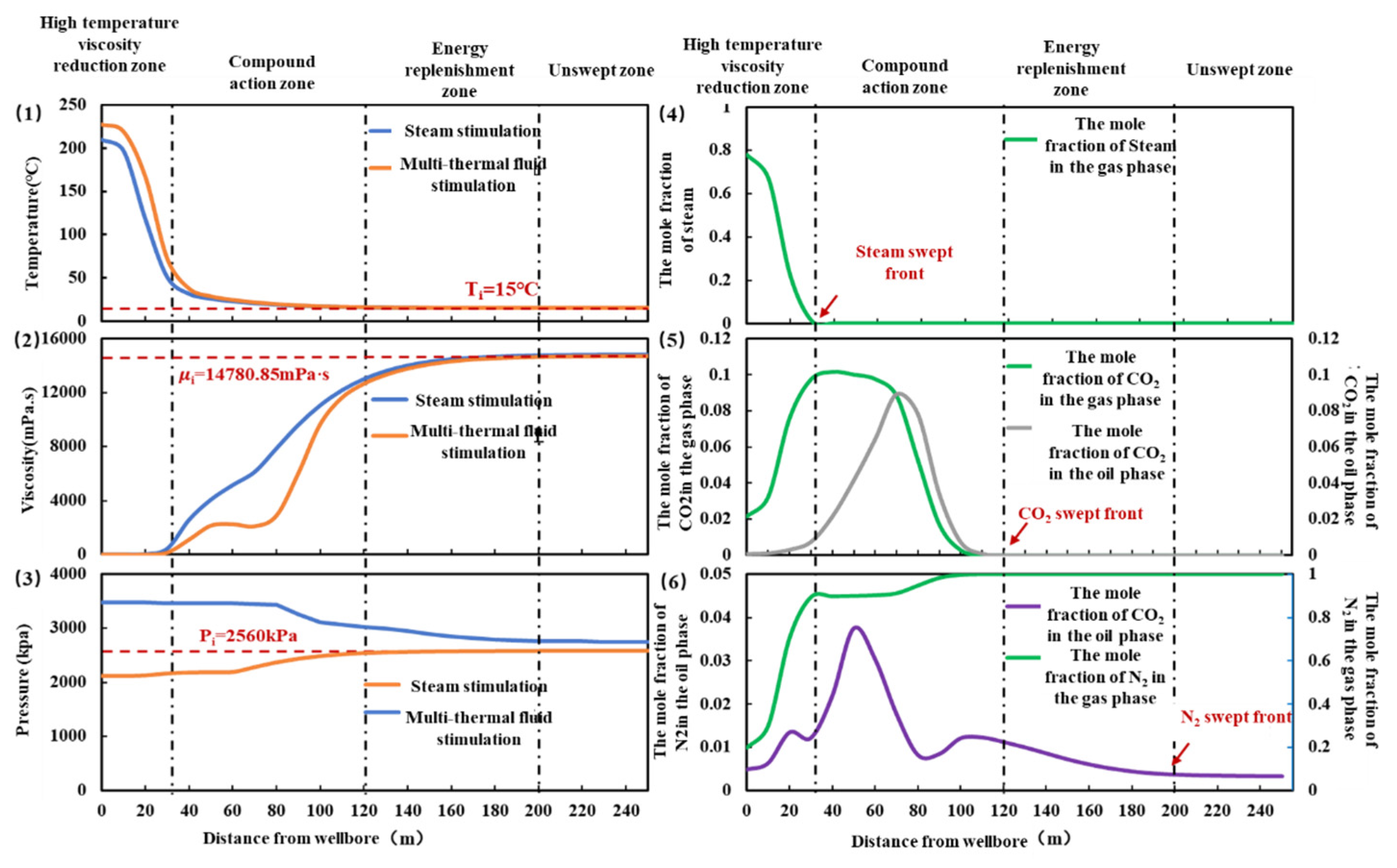
After the injection of MTF, the viscosity reduction and oil displacement processes of different media in the reservoir are dynamic. Affected by the properties of injection media and reservoir temperature and pressure, different media act on different areas and have different effects in different cycles. In order to clarify the temporal and spatial laws of MTF acting in the reservoir, and based on the distribution of steam, CO2, and N2 in the reservoir as well as the characteristics of temperature field, viscosity field, and pressure field, the action areas of MTF are divided into four areas, the high-temperature viscosity-reducing zone, the compound action zone, the energy-replenishment zone, and the unswept zone, as shown in Figure 2. Taking the wellbore as the coordinate origin, the point from the origin to the steam mole fraction of 0 is defined as the high-temperature viscosity-reducing zone, the point from the steam mole fraction of 0 to the CO2 mole fraction of 0 is defined as the composite action zone, and the point from the CO2 mole fraction of 0 to N2 mole fraction of 0 is defined as the energy-replenishment zone. [16] Figure 2 shows four different zones of MTF in the sixth cycle, in which the high-temperature viscosity-reducing zone is located in 0~30 m, the compound action zone is 30~120 m, and the energy-replenishment zone is 120~200 m.

3.2. High-Temperature Viscosity-Reduction Zone

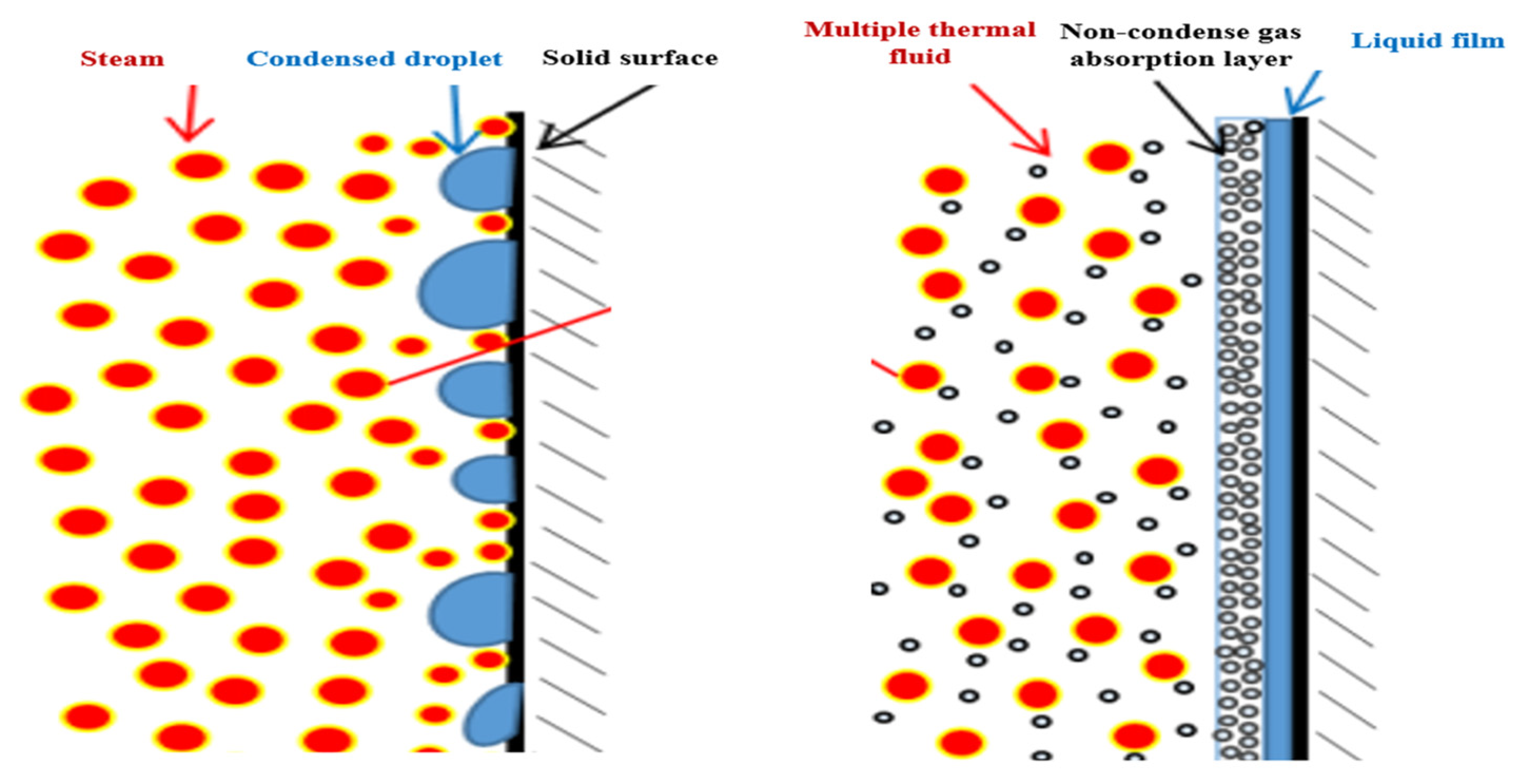
After steam is injected into the formation, it gathers 0~30 m away from the wellbore and heats the ultra-heavy oil by releasing latent heat of steamization. The temperature near the wellbore bottom increases substantially, and the viscosity of the heavy oil drops substantially to close to 0 mPa.s. In the high-temperature viscosity-reducing area, the reservoir temperature increases by 30–200 °C after cyclic steam stimulation and increases by 5–100 °C after MTF stimulation. As shown in Figure 3, non-condensate gas and steam are mixed into the reservoir. In the pores, non-condensate gas is dispersed among steam molecules, which increases the distance between steam molecules, increases the resistance of aggregation between steam molecules, and prevents water molecules from aggregating to form small water droplets. Near the surface of heavy oil and rock, steam will adsorb and condense on the surface in cyclic steam stimulation, while non-condensate gas will form a gas-enrichment layer on the surface, which will hinder the movement of steam molecules to the surface, inhibit the condensation of steam, and maintain the temperature of steam.
Nitrogen has the characteristics of low density and low-temperature conductivity. After the injection of MTF, nitrogen will diffuse to the top layer of the reservoir, which will not only inhibit steam overlap but also form a thermal insulation layer on the top layer of the reservoir and reduce the heat loss of steam. The non-condensate gas inhibits the condensation of steam in the pores and on the surface of formation and improves the utilization of heat.
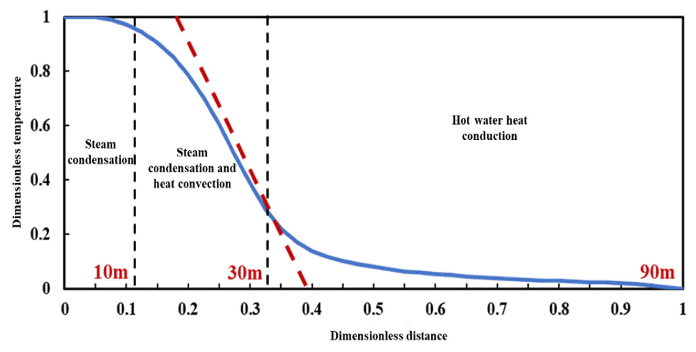
The dryness of steam in the reservoir varies with the location away from the wellbore. Therefore, the proportion of steam and hot water is different at different locations away from the wellbore, and the way of heating the crude oil is also different. According to the heating range and value of increasing formation temperature, dimensionless distance and dimensionless temperature curves are made, as shown in Figure 4. The inflection points of dimensionless distance and dimensionless temperature curves are used to divide the function areas of different heat transfer modes [17]. The inflection point is located at the 1/3 position (10 m) in the high-temperature oil-viscosity-reducing zone and the outer boundary (30 m) of the high-temperature oil-viscosity-reduction zone. At 0~10 m in the high-temperature oil-viscosity-reducing zone, the dryness of the steam is higher than 0.5. The steam in the pores transfers heat to the low-temperature heavy oil through thermal radiation, and part of the steam condenses to the rock surface to release the latent heat of steamization to heat the oil layer. In the range of 10~20 m in the high-temperature viscosity-reducing zone, the dryness of the steam decreases, and the high-temperature water from condensation increases. Under the influence of a pressure difference and non-condensate gas, the underground steam and hot water have higher fluidity, and thermal convection occurs between them and heavy oil, but the heat transfer efficiency decreases, and the reservoir temperature rise range decreases. As shown in Table 3, in the four MTF stimulation cycles, steam is concentrated within 0~30 m from the wellbore, and the heating range remains unchanged, so the action range of the oil-viscosity-reducing zone at high temperature is independent of the throughput period.

3.3. Compound Action Zone

In the compound interaction zone, steam, carbon dioxide, and nitrogen exist in different states in oil, gas, and water, and the mechanisms of different media are coupled with each other. Steam condenses and exotherms to form hot water with a relatively low temperature. CO2 is dissolved in heavy oil in a dissolved state and has a certain distribution in the gas phase, while N2 is mainly distributed in the gas phase. Its mechanism of action is mainly divided into four types: hot water reducing oil viscosity by heat transfer; CO2 dissolved in heavy oil, reducing its viscosity; and N2 and CO2 in the gas phase, preserving heat loss and recovering energy.
In the compound action zone, the inflection point of the dimensionless temperature distance curve is at the position of 90 m. In the first part of the composite zone, 30–90 m, steam turns into hot water and has a certain heating effect on heavy oil through heat conduction and heat convection, and the reservoir temperature only increases by 0~20 °C. Compared with the high-temperature oil-viscosity-reducing zone, the heating efficiency decreases significantly. In the region beyond 90 m, there is no steam and hot water, and the reservoir temperature is 15 °C of the original formation temperature.
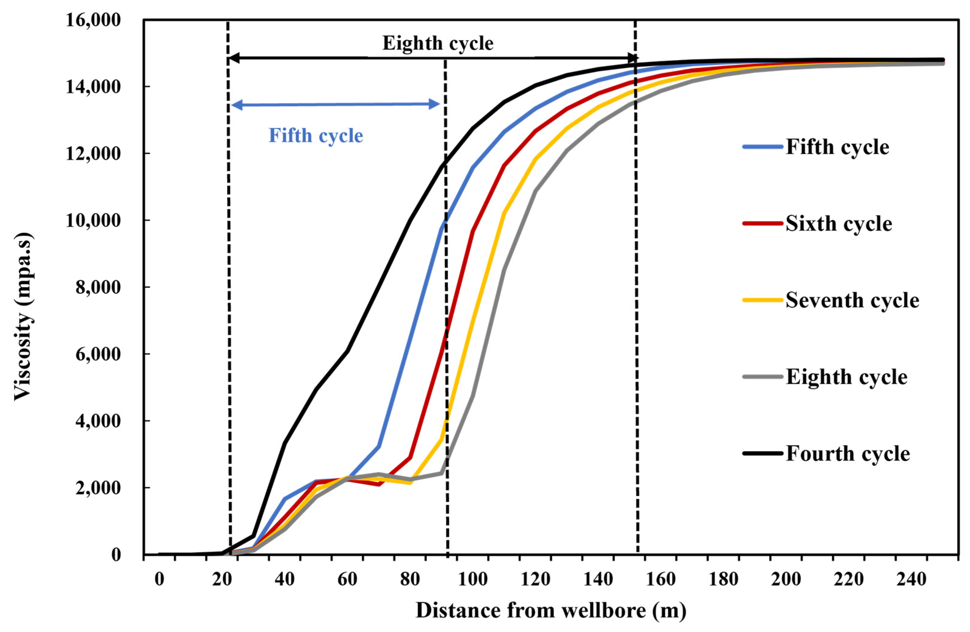
As shown in Figure 5, the heavy-oil-viscosity curve of the MTF stimulation presents a stepped shape, while the heavy-oil-viscosity curve of the cyclic steam stimulation presents a ramp shape. The viscosity curve of the MTF stimulation is mainly dominated by steam at high temperatures from 0 to 30 m, and there is little difference between MTF and steam stimulation. However, in the compound action zone, the heavy-oil viscosity in the MTF stimulation is slightly lower than that in the cyclic steam stimulation due to CO2 dissolution and N2 heat preservation, and the viscosity-reduction region in MTF is larger.
After the injection of multi-component hot fluid, a large amount of CO2 is dissolved in the heavy oil far away from the wellhead (>30 m). After the well is opened for production, the reservoir pressure drops, some of the CO2 dissolved in the heavy oil is released from the heavy oil, and some of the released CO2 is produced with the heavy oil, while some is sealed in the reservoir. In the next stimulation cycle, under the action of a pressure difference, the CO2 stored in the reservoir pores is driven to the depth of the reservoir for dissolution and viscosity reduction. Therefore, the region of CO2 dissolution and viscosity reduction increases with the increase in MTF stimulation cycle. The point where the CO2 concentration is 0 is taken as the outer boundary of the compound action zone, so the compound action zone changes obviously with the cycle of stimulation. As shown in Figure 5, the dissolution and viscosity-reduction range of the fifth cycle is 30~120 m, while the range of the composite action zone of the eighth cycle increases to 160 m, and the range expands by 10~20 m after each cycle.
With the expansion of the region of the composite action zone, the CO2 dissolution reduction and oil viscosity effects are continuously enhanced. The area enclosed by the viscosity curve of MTF and the initial formation of crude oil viscosity is taken as the viscosity-reduction amplitude, the area enclosed by the curve of steam stimulation is taken as the CO2 viscosity-reduction amplitude, and the CO2 reduction oil viscosity rate is introduced as follows:
α = 1 0 L μ i μ C S S d x 0 L μ i μ M T F d x ,
L is the distance from the wellbore to the reservoir boundary, μ i is the original reservoir formation viscosity, and μ M T F represents the crude oil viscosity in the MTF stimulation and μ C S S steam stimulation, respectively.
Since the solubility of N2 is low, the viscosity-reduction effect of N2 is not considered. The viscosity reduction in MTF is composed of high-temperature steam reducing oil viscosity, hot water reducing oil viscosity, and CO2 dissolution reducing viscosity [18,19,20]. As shown in Figure 6, the CO2 viscosity reduction rate increases with the increase in stimulation cycles. From the fifth cycle to the eighth cycle, the CO2 dissolution viscosity-reduction rate increases from 11% to 18%, but it still does not exceed 1/5. In the compound viscosity-reduction zone, hot water heat transfer is still the main viscosity reduction, while the CO2 dissolution viscosity reduction plays only an auxiliary role. From the fifth cycle to the eighth cycle, the viscosity-reduction rate of the composite action zone ranges from 47.28% to 67.26%. In the last two cycles of MTF stimulation, the viscosity-reduction range of the composite action zone is higher than that of the high-temperature viscosity-reduction zone of steam, occupying the main position. With the increase in stimulation cycle, the reservoir pressure decreases, and some dissolved CO2 is precipitated, but it still exists in the form of foam oil, improving the fluidity of heavy oil.
In the compound action zone, N2 and CO2 in the gas phase have good expansibility and can increase reservoir pressure. In order to study the pressurization effect of non-condensate gas, the pressure field in the MTF stimulation is different from that in steam stimulation, and the pressure increase value in the MTF stimulation is obtained, as shown in Figure 7. In the cyclic steam stimulation, the steam condenses quickly and does not have a pressure increase effect. In the MTF stimulation, the non-condensate gas molecules are between the steam molecules, increasing the volume of the steam and providing a certain pressurization effect in the high-temperature viscosity-reducing region. A large amount of non-condensate gas, N2 and CO2, is distributed in the compound action zone, so it has a good pressurization effect. With the increase in distance, the concentration of non-condensate gas decreases, so the effects of pressure maintenance and energy increases are weakened.

3.4. Energy-Replenishment Zone

The replenishment zone is from the point of a CO2 concentration of 0 to the starting pressure gradient of heavy oil. Compared with CO2, N2 has better fluidity, so only a small amount of N2 plays the role of maintaining pressure and increasing energy in the energy-replenishment area. As shown in Figure 7, in the fifth cycle, N2 spreads to 170 m due to the small amount of injection. The energy-replenishment area is smaller and the pressurization range is lower than in other cycles. N2 diffuses to the reservoir boundary after the fifth cycle. The gas injection and displacement in each cycle reaches a balance, and the increase in pressure remains basically unchanged. It can be seen that the energy replenishment zone is affected by the concentration of CO2 and N2 at the same time. The concentration of CO2 determines the inner boundary of the replenishment zone, and the concentration of N2 determines the outer boundary.
With the increase in stimulation cycle, the point of a CO2 concentration of 0 is further and further from the wellbore, and the inner boundary in the replenishment area is further away from the wellbore. When N2 diffuses to the reservoir boundary, the outer boundary remains unchanged and the energy-replenishment zone decreases continuously. After the steam stimulation switches to the MTF stimulation, the energy replenishment of non-condensate gas in the composite and replenishment zones results in a rapid increase in wellbore-bottom flow pressure.

3.5. Analysis of Contribution Rate of Oil Production in Different Zones

The mechanism of MTF is different in different zones in the reservoir, and the contribution of different mechanisms to oil production is different. In this paper, the ratio of crude oil outflow in each zone to cyclic oil production is defined as the contribution rate of oil production. The change law of the contribution rate in each zone in different stimulation cycles is studied.
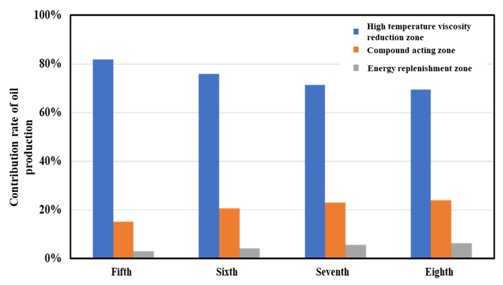
As shown in Figure 8, 70% to 80% of productivity comes from the high-temperature viscosity-reduction zone, while the contribution rate of productivity 30 m away from the wellbore is only 20% to 30%. With the increase in throughput cycle, the near-well oil saturation decreases, the heavy oil in large pores is gradually extracted, and the remaining oil mainly exists in small pores with poor fluidity. After four throughput cycles, the contribution rate of the high-temperature viscosity-reducing zone decreases by 12.35%. The contribution rate of oil production in the combined action zone and the replenishment zone increases gradually, reaching up to 30% of the total production. The contribution rate of the compound action zone increases from 15.24% to 26.06%, and the contribution rate of the supplementary-energy zone increases from 2.98% to 4.53%. The contribution rate of the composite action zone is much higher than that of the supplementary-energy zone. In the later stage of the MTF stimulation, by increasing the injection amount of steam and non-condensate gas, the oil-viscosity-reduction effect is enhanced, and the heavy oil in the composite action zone and replenishment zone is driven to the near-well zone, and the heavy oil far away from the wellbore can be used to maintain stable production.

4. Conclusions

(1) The positive effect of MTF stimulation is obvious in M oilfield. After switching to MTF stimulation, the productivity of well M-4 is greatly increased, the stable production period is prolonged, water cuts are reduced, and bottom-hole flow pressure is increased. After multiple-cycle stimulation, the daily oil production decreases, but the water content and bottom-hole flow pressure basically remain stable. M oilfield is an ultra-heavy-oil reservoir with more periodic gas injection and an earlier MTF transfer time. If MTF is applied to conventional heavy-oil reservoirs, oil can be produced by reducing steam and gas injection, and MTF implementation can be appropriately delayed.
(2) From the wellbore to the reservoir boundary, according to the effect of different media, there are three different zones: the high-temperature viscosity-reducing zone, compound action zone, and energy-replenishment zone. The mechanism of the composite action zone includes reducing oil viscosity by hot water, CO2 dissolution in the oil phase, and thermal insulation and energy enhancement by CO2 and N2 in the gas phase. The coupling effect of three different zones increases cyclic oil production.
(3) In the MTF stimulation, the high-temperature viscosity-reducing zone plays a dominant role in the productivity contribution, while the compound action zone and the replenishment zone only play auxiliary roles. At the initial stage of stimulation, the contribution rate of oil production in the high-temperature viscosity-reducing zone can reach 80%, while that in the compound action zone and recharge zone accounts only for 20%. With the increase in stimulation cycles, the range of the compound action zone increases, the range of the energy-replenishment zone decreases, and the contribution rate of the oil production of both zones increases to 30%.

Author Contributions

Conceptualization and methodology, H.M., B.B. and. A.X.; validation, S.W., C.W. and M.L.; formal analysis, F.S.; resources, L.Z.; data curation, G.M.; writing—original draft preparation, H.M.; writing—review and editing, H.M. and B.B. All authors have read and agreed to the published version of the manuscript.

Funding

This research was funded by Basic and Prospective Project of “14th Five-Year Plan” of PetroChina Company Limited: Research on Application of Heavy Oil MTF Stimulation Development Technology in Central Asia and America (2021DJ3207).

Institutional Review Board Statement

Not applicable.

Data Availability Statement

The original contributions presented in the study are included in the article, further inquiries can be directed to the corresponding author.

Conflicts of Interest

The authors declare no conflicts of interest.

References

  1. Zhang, F.; Xu, W.; Wu, T.; Ge, T.; Wang, H.; Wu, C.; Wang, D. Research on the mechanism of MTFs on enhanced oil recovery and reservoir adaptability. Pet. Geol. Recovery Effic. 2014, 21, 75–78. [Google Scholar]
  2. Liu, D.; Hu, T.; Pan, G.; Wu, J.; Zhang, J. Comparison of Production Results between MTF Stimulation and Steam Stimulation in Offshore Application. Spec. Oil Gas Reserv. 2015, 22, 118–120. [Google Scholar]
  3. Feng, X.; Li, J.; Yang, B.; Shi, H. Research on Optimization Design for Increasing Production of Offshore Heavy Oil Multi-thermal Fluid Handling Components. J. Chongqing Univ. Sci. Technol. (Nat. Sci. Ed.) 2018, 20, 28–32. [Google Scholar]
  4. Chen, J. Multiple thermal fluid huff-puff in offshore deep thin heavy oil reservoir. Spec. Oil Gas Reserv. 2016, 23, 97–100+155–156. [Google Scholar]
  5. Zhang, W.; Sun, Y.; Lin, T.; Ma, Z.; Sun, Y.; Liu, H. Experimental study on mechanisms of the Multi-fluid thermal recovery on offshore heavy oil. Petrochem. Ind. Appl. 2013, 32, 34–36. [Google Scholar]
  6. Ge, T.; Pang, Z.; Luo, C.; Gao, Z.; Du, C. Experimental study on MTF flooding by using horizontal wells in offshore heavy oil reservoirs. Pet. Geol. Recovery Effic. 2019, 26, 62–69. [Google Scholar]
  7. Yang, B.; Li, J.; Qi, C.; Shi, H.; Zhu, W. Research on optimized MTFs stimulation of offshore heavy oil reservoirs. Pet. Geol. Eng. 2012, 26, 54–56. [Google Scholar]
  8. Lu, T.; Ban, X.; Li, Z.; Gao, Y.; Guo, E.; Yang, J.; Ma, H.; Wang, H.; Wei, Y. Mechanisms on expansion of SAGD steam chamber assisted by flue gas. Acta Pet. Sin. 2021, 42, 1072–1080. [Google Scholar]
  9. Wang, Z. Study of Steam Heat Transfer Law in Development of Flue Gas Assisted SAGD; China University of Petroleum (East China): Dongying, China, 2019. [Google Scholar]
  10. Huang, Z.; Zhao, Q.; Chen, L.; Miao, Y.; Wang, Y.; Jin, H.; Guo, L. Fundamentals of Enhanced Heavy Oil Recovery by Supercritical MTF Flooding. J. Eng. Thermophys. 2022, 43, 974–981. [Google Scholar]
  11. Huang, S.; Cao, M.; Cheng, L. Experimental study on the mechanism of enhanced oil recovery by MTF in offshore heavy oil. Int. J. Heat Mass Transf. 2018, 122, 1074–1084. [Google Scholar] [CrossRef]
  12. Huang, Z.; Zhao, Q.; Chen, L.; Guo, L.; Miao, Y.; Wang, Y.; Jin, H. Experimental investigation of enhanced oil recovery and in-situ upgrading of heavy oil via CO2-and N2-assisted supercritical water flooding. Chem. Eng. Sci. 2023, 268, 118378. [Google Scholar] [CrossRef]
  13. Zhang, N.; Zhu, R.; Zhu, Y. MTF Huff-Puff Mechanism Based on Discrete Wellbore Model. Xinjiang Pet. Geol. 2020, 9, 332–336. [Google Scholar]
  14. Liu, Y.; Wang, C.; Li, X.; Xu, H. Development mechanism of multivariate thermal fluid of deep super-heavy oil. Fault-Block Oil Gas Field 2019, 26, 638–643. [Google Scholar]
  15. Zhang, T.; Li, Y.; Sun, S.; Bai, H. Accelerating flash calculations in unconventional reservoirs considering capillary pressure using an optimized deep learning algorithm. J. Pet. Sci. Eng. 2020, 195, 107886. [Google Scholar] [CrossRef]
  16. Zhou, Y. Studies and practices on the steam injection EOR of water drived heavy oil reservoirs in Shengli petroliferous province. Pet. Explor. Dev. 2006, 33, 479–483. [Google Scholar]
  17. Lawal, K.A.; Vesovic, V. Analytic investigation of convection during conduction heating of a heavy-oil reservoir. In SPE Annual Technical Conference and Exhibition; OnePetro: Richardson, TX, USA, 2009. [Google Scholar]
  18. Wang, F.; Mou, Z.; Liu, P.; Zhang, S.; Wang, C.; Li, X. Experiment and numerical simulation on mechanism of CO2 assisted mining in ultra heavy oil reservoirs. Pet. Geol. Recovery Effic. 2017, 24, 86–91. [Google Scholar]
  19. Zhou, W.; Kou, G.; Zhang, Z.; An, K.; Liu, S.; Liu, Y. Steam-CO2 Flooding for Heavy Oil in District 9-6, Karamay Oilfield: Experiment and Evaluation. Xinjiang Pet. Geol. 2019, 40, 204–207. [Google Scholar]
  20. Leng, G. Laboratory Study on Air and CO2 Assisted Steam Stimulation. Oil Chem. 2018, 35, 447–450. [Google Scholar]
Figure 1. Production curves of well M-4. (1) Daily oil production curve. (2) Water content curve.
Energies 17 02129 g001
Figure 2. Mechanism partition of MTF. (1) Temperature curves of CSS and MTF; (2) Viscosity of CSS and MTF; (3) Pressure curves of CSS and MTF; (4) The mole fraction of steam in the gas phase; (5) The mole fraction of CO2 in the gas and oil phase; (6) The mole fraction of N2 in the gas and oil phase.
Energies 17 02129 g002
Figure 3. Comparison of steam stimulation with MTF stimulation in steam condensation.
Energies 17 02129 g003
Figure 4. Dimensionless temperature distribution curve.
Energies 17 02129 g004
Figure 5. Viscosity changes in MTF in different cycles.
Energies 17 02129 g005
Figure 6. Changes in CO2 viscosity reduction in MTF in different cycles.
Energies 17 02129 g006
Figure 7. Pressure increase in MTF in different cycles.
Energies 17 02129 g007
Figure 8. Contribution rate of oil production in each zone.
Energies 17 02129 g008
Table 1. M-4 injection and production data for each cycle.
Stimulation
Cycles
Steam (t)Carbon
Dioxide (t)
Nitrogen (t)Cumulative Oil Production (t)Oil–Steam Ratio (t/t)
First cycle2206//298.10.135
Second cycle5460//400.80.073
Third cycle4324//828.90.192
Fourth cycle4468//501.90.112
Fifth cycle4037//475.10.118
Sixth cycle1506370.081765.923434.72.281
Seventh cycle35311454.436940.174727.61.339
Eighth cycle40251614.557704.214513.01.121
Table 2. Model parameters.
Reservoir
Parameters
Number of GridsMesh Size (m)PorosityHorizontal
Permeability (mD)
Vertical
Permeability (mD)
Numerical value50 × 50 × 1510 × 10 × 228.12656796.8
Reservoir
parameters
Sag ratioOriginal formation
viscosity (mPa.s)
Original oil
Saturation (%)
Original formation
temperature (°C)
Original formation pressure (MPa)
Numerical value0.314,780.8575152.56
Production
parameters
Daily water
injection (m3/d)
Daily steam injection
volume
N2 to CO2
volume ratio
Injection
duration (d)
Soaking time (d)
Numerical value20079,8009:1205
Production
parameters
Production
time (d)
Throughput cycleCSS cyclesMTF cycles
Numerical value300844
Table 3. Changes in the range of action in different stimulation cycles.
The Fifth
Cycle
The Sixth
Cycle
The Seventh
Cycle
The Eighth
Cycle
High-temperature oil-viscosity-reduction zone0~30 m0~30 m0~30 m0~30 m
Compound action zone30~120 m30~135 m30~148 m30~160 m
Energy-replenishment zone120~170 m135~200 m148~200 m160~200 m
Disclaimer/Publisher’s Note: The statements, opinions and data contained in all publications are solely those of the individual author(s) and contributor(s) and not of MDPI and/or the editor(s). MDPI and/or the editor(s) disclaim responsibility for any injury to people or property resulting from any ideas, methods, instructions or products referred to in the content.