Abstract
The occurrence of short-circuit faults in AC/DC microgrids gives rise to exceptionally high currents with rapid escalation, particularly in DC feeders where current zero-crossing is absent. This study introduces a comprehensive design procedure for a solid-state breaker tailored to address this challenge. A key innovation of the proposed solid-state circuit breaker lies in the incorporation of a current limiter reactor, which effectively constrains the current flow in both the load commutation switch and main breakers. Additionally, the inclusion of a resistive branch diminishes energy dissipation in the main breakers, safeguarding them against voltage stress. Consequently, the operational efficiency of the breaker is significantly enhanced, ensuring swift and efficient fault current interruption in vulnerable AC/DC microgrid scenarios. The efficacy of the proposed solid-state breaker was rigorously examined through analytical studies, and the results were validated using MATLAB/Simulink simulations. This breakthrough design represents a promising advancement in the realm of microgrid protection, offering a robust solution for mitigating the impact of short-circuit faults in AC/DC systems.
1. Introduction
The past decade has witnessed the emergence of the microgrid concept as a transformative solution to enhance distribution systems. This innovative paradigm redefines the landscape of distributed generation and power electronic operations by establishing a microgrid that seamlessly integrates loads and interfaces with a distribution network. A notable configuration within the realm of modern microgrids is the AC/DC hybrid microgrid, which effectively amalgamates DC and AC systems. This configuration serves as an efficient means of interconnecting DC and AC generators within a network, thereby marking a significant advancement in power distribution systems [1]. In this context, we observed advancements in DC/DC [2] and AC/DC [3] converter technologies.
Considering the vulnerability of microgrid equipment, it is always endangered by probable short-circuit faults [4]. Microgrid protection schemes can be classified as voltage-based protection [5,6], adaptive protection, differential protection, distance protection, overcurrent protection, techniques that utilize external devices, coordinated protection techniques, etc. Multiple protection strategies can be used because of the complexity of microgrids. These methodologies need to adhere to the criteria for operating in both grid-connected and islanded modes, addressing faults occurring either within or outside the microgrid [7]. Hybrid AC/DC microgrids include renewable energy sources, such as photovoltaic panels and wind turbines, distributed generators (DGs), including diesel generators and micro-turbines, and resistive loads that can be directly connected to the AC and DC, and motor drives, which are needed to be protected by modern protection devices [8].
Fault current limiters (FCLs) are significant protection systems that have recently been commercialized in power grids. These are also applicable protection mechanisms for AC/DC microgrid protection [9]. Among the diverse types of FCLs, superconductive FCLs [10], series transformer-type FCLs [11], and saturated core FCLs [12] are suitable for implementation in microgrids. In [13], a fault-managing strategy was presented through the FCL to protect the inverter in the microgrid. The superconductor FCL (SFCL) has been suggested to improve the transient performance of a microgrid during a fault [14]. In [15], a comparison between SFCL and a dynamic voltage restorer (DVR) for the low-voltage ride-through (LVRT) capability enhancement of a 10 kV microgrid was performed. DC microgrid protection was considered using a high-temperature SFCL in [16], and the integration of FCL for protecting bus voltage was debated in [17].
A unidirectional fault current limiter (UFCL) is a protection device that has recently been developed for microgrids from upstream grid faults [18]. In [19], a unified structure is given that can connect both AC and DC lines and manage the value of the current flow on both sides. Therefore, the mentioned method can be used to develop a new UFCL to protect AC/DC microgrids. Moreover, the comprehensive protection of AC/DC microgrids requires the use of a solid-state fault current breaker [20]. Another solid-state was developed and tested for the DC microgrid in [21]. Solid-state breakers use electronic components for control and operation. The control systems in these breakers can detect faults and trigger interruptions much faster than the mechanical systems in traditional breakers. This electronic control enables precise and rapid response times. This makes them suitable for protecting AC/DC microgrids. The primary concern in this domain revolves around the advancement of effective solid-state breakers with fault-limiting capabilities aimed at swiftly safeguarding both AC and DC microgrids from fault currents, thus preventing damage to susceptible equipment within AC/DC microgrids.
In this study, a coupled reactor-based solid-state circuit breaker (CR-SSCB) is presented for AC/DC microgrid protection. At fault inception, coupled reactors limit the current of the latch check switch (LCS), and by opening the middle branch of the bridge, the current is conducted by the main breakers (MBs). Resistors and coupled coils limit the amount of line current that can be conducted with the line’s MB. The contributions of this study are as follows.
- The ability of the proposed CR-SSCB to operate in both DC and AC systems;
- The proper protection of power electronic equipment in the AC/DC microgrid;
- Limiting the rate of the increasing fault current in the R-L circuit;
- Fast operation;
- Two-stage operation to limit the voltage stress of the circuit breaker during its operation.
The remainder of this paper is organized as follows: Section 2 presents the topology of CR-SSCB, and in Section 3, an analytical study of the proposed structure is provided. In the next section, the CR-SSCB simulation is carried out on both the AC and DC lines. Finally, the conclusions are presented in Section 5.
2. CR-SSCB Placement and Topology
In this section, the fast protection of the AC/DC microgrid is presented considering that the CR-SSCB is protected by both AC and DC generators. As shown in Figure 1, an AC/DC microgrid includes AC generators, an AC load, a DC generator, a DC load, and a coupling inverter that is connected to the grid via a transformer. In this microgrid, AC and DC generators are protected by the same CR-SSCB breakers.
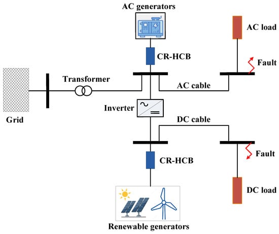
Figure 1.
CR-SSCB placement in AC/DC microgrid.
The proposed solid-state breaker is illustrated in Figure 2. As is clear in this figure, five branches are considered, wherein the coupled coils of branches 1 and 2 are located. These two coils are coupled by a magnetic core, which increases the series impedance through the mutual inductance. In branches 3 and 4, the resistors and MBs were connected in series. An IGBT switch-based LCS with a voltage rating of 4.5 kV and current rating of 1 kA and a series ultrafast disconnector (UFD) are connected to the middle branch to allow the main power to flow in the AC or DC line. Moreover, surge arresters are connected in parallel with the MBs to dampen the energy of the passive elements. In the following, the operation of CR-SSCB is explained using three different modes: the normal operation mode, pre-fault breaking mode, and fault breaking mode in both AC and DC systems.
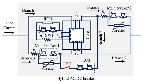
Figure 2.
Topology of the proposed CR-SSCB.
2.1. Normal Operation Mode
The normal operation mode can be divided into steady-state and dynamic-state modes. In a steady-state model, the MBs and SW1 are off, and LCS and UFD are off. Therefore, the unrippled current flows through coil , coil , UFD, and LCS, as indicated in Figure 3. In addition, in the fault current limiter topology, the IGBT switch (SW1) is turned off, and there are no current dynamics. Therefore, the only effect of a fault-limiter reactor is its resistive effect, which is negligible. Therefore, the limiter reactor is modeled as a short circuit, the limiter reactor’s voltage drop is assumed to be zero, and the LCS and UFD conduct the line current with minimal power loss. Moreover, given that in the normal condition, both and are bypassed, the UFD effectively conducts the circuit, and LCS serves as a bidirectional low-impedance switch. Consequently, the CR-SSCB has minimal impact on the power quality of AC systems in microgrids.
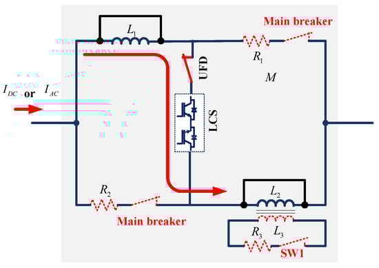
Figure 3.
CR-SSCB in the normal operation mode (steady-state). The red arrow shows the current direction.
In the dynamic state, the MBs are off, and SW1, LCS, and UFD are on. In this situation, as shown in Figure 4, the coupled reactor can behave as series impedance, but the bypass reactor ( is operated by SW1 to generate a reverse flux in the core and decrease the series impedance of the reactors to a very low value. To limit the current of SW1 in the dynamic state, a small resistor is connected in series with SW1.
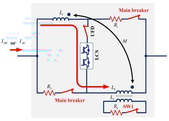
Figure 4.
CR-SSCB in the normal operation mode (dynamic state). The red arrow shows the current direction, and the black arrow shows the mutual inductance.
2.2. Pre-Fault Breaking Mode (Stage 1)
In the pre-breaking mode, the line fault current can result in a remarkably high rate of increase in the current at the fault inception in both AC and DC systems; however, by operating the connected coils and , the fault current is minimized. In addition, the magnetic core sums the fluxes and and increases the equivalent series inductance. In the next step, LCS is opened after 0.2 ms considering the operational delay of conventional IGBTs, and the current of the line is conducted by two parallel paths consisting of series , , first MB, and , , and second MB. In this condition, UFD is operated within 2 ms, considering the mechanical delay of conventional fast disconnectors to disconnect the LCS. Therefore, LCS is closed from high voltage stress, and the topology is ready for the breaking operation.
2.3. Fault-Breaking Mode (Stage 2)
Figure 5 shows the topology of the circuit breaker in the fault-breaking mode. In this operation mode, the fault currents in both the DC and AC systems are limited by the two coupled coils, and the current flows through two R-L branches. Two milliseconds after fault occurrence and by operating the UFD to disconnect with the LCS switch, two MBs isolate both AC and DC systems. Whenever each MB opens half of the line current, the surge arrester is activated to dump the system’s stored energy and suppress the voltage stress of the MB. Furthermore, and aid in fault current limitation and energy dump.
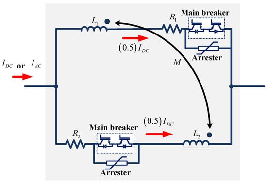
Figure 5.
CR-SSCB operation in the fault-breaking mode for an AC/DC system. The black arrow shows the mutual inductance.
3. Analytical Study of CR-SSCB
This section covers theoretical aspects of CR-SSCB performance. Important variables like voltage drop, current, and power loss are, therefore, computed and examined. Because of this, the behavior of the CR-SSCB in the DC and AC systems is explained separately in the following.
3.1. CR-SSCB Operation Analysis in the DC System
3.1.1. Normal Operation Mode
This analysis was conducted considering the CR-SSCB equivalent circuit in Figure 3. In this case, the DC line current did not change, except that the solid-state switch in the secondary part was off. Additionally, the resistances of series reactors ( and ) were small. Due to this issue, the DC current did not pass through the resistors and . In this condition, the CR-SSCB voltage drop and power loss are written as (1) and (2) as follows:
where is the voltage drop of CR-SSCB. and are the resistances of both series reactors. is the current of the DC line in the microgrid and is the power loss of CR-SSCB.
In dynamic conditions, system dynamics cause the DC line current to fluctuate. According to the equivalent circuit in Figure 4, SW1 is turned on to dampen the dynamic behavior of the system. Therefore, the current of the secondary part of the series reactor generates a reverse flux, which releases the effects of the series reactor. The voltage drops and there is power loss of the CR-SSCB, as shown in Equations (3) and (4).
where and represent the series reactor’s winding turns. , and are a flux of the coupled series reactors and is the reverse flux generated by the secondary controlling coil . And refers to the secondary current of the .
3.1.2. Pre-Fault Breaking Mode
In this state, the fault is limited to preparing a well condition to break the fault current. Thus, the solid-state switch is turned off to limit the fault current by imposing high inductance via and . Therefore, the voltage drop and power loss of the CR-SSCB can be calculated using the following formula:
3.1.3. Fault-Breaking Mode
In the final operation mode, the LCS switch is opened in the middle branch of the CR-SSCB. Therefore, the breaker conducts the fault current in two parallel branches, as shown in Figure 5. The voltage drop of the breaker is presented in (7), and the power loss before opening the MB is presented in (8) as follows:
where and are the limiter resistors of the MBs.
3.2. CR-SSCB Operation Analysis in AC System
3.2.1. Normal Operation Mode
In this situation, the AC line current passes through coupled series reactors, which are bypassed by the secondary control coil and solid-state switch. In addition, the system can be in either a dynamic or steady-state condition. The voltage drops of the CR-SSCB are presented in (9), and its power loss is the same as (4).
In this equation, it is considered that the voltage of the source ( in the microgrid is sinusoidal, as presented in Equation (10).
where ω is the angle velocity of AC voltage, and f is the system frequency. Considering equal to ,
where and are the leakage impedance of the bypassed series reactors and and are the series reactor leakage inductances.
3.2.2. Pre-Fault Breaking Mode
In this case, the fault current must be limited by imposing a high impedance of series reactor coils by turning off the solid-state controlling switch in this operation. The voltage drops of the CR-SSCB are shown in (13).
where is the line current in the AC line of the microgrid, and M is the mutual inductance of series coils. In this situation, power loss can be calculated as likely (6).
3.2.3. Fault-Breaking Mode
In the fault-breaking mode, LCS opens the middle branch to commute fault currents to the MBs. Due to the operation of LCS, the fault current is divided into two parts, which are conducted by parallel MBs, as shown in Figure 5. The voltage drop and power loss of CR-SSCB are calculated in (14) and (15) as follows:
4. Simulation of CR-SSCB in AC/DC Microgrid
In this research, MATLAB/Simulink was used to model the AC/DC system, as shown in Figure 1, using the parameters listed in Table 1. For this reason, two scenarios were considered and are explained in Section 4.1 and Section 4.2. In the first scenario, it was assumed that the fault occurred in the DC system and that the current from the DC source in the microgrid could be interrupted by the CR-SSCB. In the second scenario, it was assumed that a short-circuit fault occurred in the AC system, and the CR-SSCB operates to protect the AC source of the microgrid.

Table 1.
Parameters of the simulation system.
4.1. DC System Fault Simulation
In this section, we presume the occurrence of a fault within the DC system, as depicted in Figure 1. The DC generators, as a vulnerable part of the AC/DC microgrid, engage in proving the massive amounts of the DC fault current considering the impedance between the DC fault and DC sources. Hence, DC generators need to be protected by CR-SSCB. Figure 6 illustrates the DC line current during normal and fault conditions. In the first stage, the fault is limited by the controlled reactors, and , and then (at ) LCS commutes the current into MBs and resistor limiter branches, which experience the first peak at approximately 700 A. Throughout the UFD operation to disconnect LCS, the DC line current is moderately increased to reach the sconed peak at approximately 900 A. The operational time of CR-SSCB to break the DC fault current is 3 ms, which is an appropriate time for DC system protection.
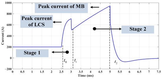
Figure 6.
DC line current of AC/DC microgrid in normal and fault conditions.
Additionally, to show the safety of the proposed CR-SSCB, Figure 7 concentrates on the voltage stress of the CR-SSCB, which experiences two voltage peaks as the fault limitation recovery voltage (LRV) at 18 kV and a second peak voltage as transient recovery voltage (TRV) at 39 kV. The value of the voltage stress is not much higher than the DC system’s normal voltage (20 kV), which proves the capability of the CR-SSCB to limit the fault current.
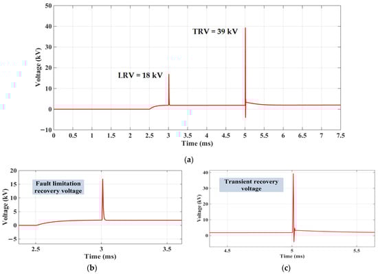
Figure 7.
Voltage stress of the CR-SSCB in the DC system.
4.2. AC System Fault Simulation
In the second part of the simulation, it is considered that a fault occurred in the AC system in Figure 1. Based on the low impedance between the fault and AC sources, they must be protected from the high magnitude of the fault current. Hence, in this simulation, CR-SSCB is connected in series with an AC generator to break the fault current as soon as possible. The AC line current is shown in both the fault state and normal modes in Figure 8. It is demonstrated that once a current of 400 A is reached, the fault is stopped. The detailed examination of the line current (Figure 8b) is depicted following its interruption, having undergone two peak currents at 250 A and 400 A, respectively.
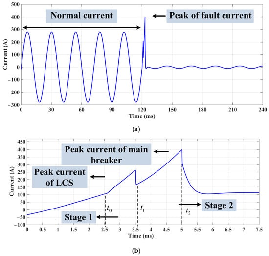
Figure 8.
AC line current: (a) normal and fault condition; (b) close view of the peak current.
Figure 9 shows the voltage stress of the CR-SSCB in the case of fault limiting and breaking operations. According to this result, the magnitudes of the LRV and TRV are 20 kV and 37 kV, respectively. It should be mentioned that the peak of the voltage is 20 kV. Therefore, these values are less than twice the peak value of the AC system voltage. This demonstrates the capacity of the suggested CR-SSCB to safeguard the AC system with reduced equipment failure risk and increased energy efficiency.
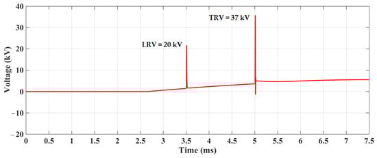
Figure 9.
Voltage stress of the CR-SSCB in the AC system.
4.3. CR-SSCB Performance in AC and DC Systems
To discuss the performance of the CR-SSCB, key features should be considered. These could include the operational time, peak values of current and voltage stress, a limited current rate, dissipated energy, and the number of switches. These values were measured and calculated for both AC and DC systems, which were simulated in Section 4.1 and Section 4.2 and summarized in Table 2. The operational time for both DC and AC systems was equal, and the voltage stress of the breaker nearly occurred for both systems. However, there were big differences between the rate at which the current rose and the value of dissipated energy, which can be related to differences between the AC and DC systems. To sum up the result of the comparison, it is clear that the operation of the CR-SSCB successfully protected both the AC and DC systems of the microgrid.
Table 2.
Key features of the proposed CR-SSCB application in an AC/DC microgrid.
It should be mentioned that both the AC and DC systems can experience fault currents. However, the rate at which the current tends to increase is faster and more severe in DC systems, requiring robust protection mechanisms to mitigate the impact of faults. This is because in DC systems, there is no natural zero-crossing point in the current waveform, and there may be limited or no inductance to dampen the rate of increase in the current during faults. As a result, faults in DC systems can lead to very rapid increases in current, potentially causing significant damage to the equipment if not quickly controlled.
To illustrate the advantages of the proposed CR-SSCB over relevant technologies, Table 3 presents a comparison between H-bridge breakers, DC hybrid breakers, and UFCL. As is evident, the primary advantage of CR-SSCB is its ability to operate in both AC and DC systems. Additionally, this table indicates that the proposed breaker operates with the shortest time (3 ms) and experiences minimal voltage stress.
Table 3.
Comparison of the proposed CR-SSCB features with other related breakers.
5. Conclusions
In this paper, an AC/DC breaker is presented to protect the AC/DC microgrid from the sharp rise in the fault current. This breaker was developed based on a controllable reactor and mechanical disconnector, which is called a controllable reactor hybrid circuit breaker. The analytical and simulation results improved the performance of the breaker to limit and break the fault current in both DC and AC systems with an exceedingly small operational time of approximately 3 ms. The simulation results show that the rate at which the voltage increased for both AC and DC was the same. However, the rate at which the current increased in the DC system was six times higher than that in the AC system. This resulted in higher energy loss in the DC system compared to the AC system. Nevertheless, the results show that the new CR-SSCB can work successfully in both DC and AC systems, with fast response and reduced equipment failure risk. In short, the comparatively fast speed, low voltage stress, and capability to function on both the AC and DC sides of AC/DC microgrids are the primary benefits of the suggested breaker. In this research, the theory and feasibility of the proposed CR-SSCB are demonstrated by simulation. The next step will be an actual experiment to prove the correct operation of CR-SSCB in real conditions.
Author Contributions
Conceptualization, A.B. and A.M.; methodology, A.B. and A.M.; software, A.B.; validation, A.B., A.M. and M.H.; formal analysis, A.B.; investigation, A.B.; writing—original draft preparation, A.B.; writing—review and editing, M.H.; supervision, A.M. All authors have read and agreed to the published version of the manuscript.
Funding
This research received no external funding.
Data Availability Statement
Data will be made available on request.
Conflicts of Interest
The authors declare no conflicts of interest.
Abbreviations
| Abbreviation | Description |
| CR-SSCB | coupled reactor-based solid-state circuit breaker |
| DVR | dynamic voltage restorer |
| FCL | fault current limiter |
| IGBT | integrated gate bipolar transistor |
| LCS | load commutation switch |
| MB | main breaker |
| PV | photovoltaic |
| UFCL | unidirectional fault current limiter |
| UFD | ultrafast disconnector |
References
- Sinha, R.R.; Kanwar, N. Chapter Four—Hybrid microgrids: Architecture, modeling, limitations, and solutions. In Modelling and Control Dynamics in Microgrid Systems with Renewable Energy Resources; Academic Press: Cambridge, MA, USA, 2024. [Google Scholar]
- Min, J.; Ordonez, M. Bidirectional Resonant CLLC Charger for Wide Battery Voltage Range: Asymmetric Parameters Methodology. IEEE Trans. Power Electron. 2021, 36, 6662–6673. [Google Scholar] [CrossRef]
- Min, J.; Ordonez, M. Cascaded Half-Bridge-Based Bidirectional Multilevel Bridgeless PFC With Multioutput Ports. IEEE Trans. Power Electron. 2023, 38, 16034–16047. [Google Scholar] [CrossRef]
- Shafaghatian, N.; Heidary, A.; Radmanesh, H.; Rouzbehi, K. Microgrids interconnection to upstream AC grid using a dual-function fault current limiter and power flow controller: Principle and test results. IET Energy Syst. Integr. 2019, 1, 269–275. [Google Scholar] [CrossRef]
- Heidary, A.; Rouzbehi, K.; Radmanesh, H.; Pou, J. Voltage Transformer Ferroresonance: An Inhibitor Device. IEEE Trans. Power Deliv. 2020, 35, 2731–2733. [Google Scholar] [CrossRef]
- Heidary, A.; Radmanesh, H.; Bakhshi, A.; Samandarpour, S.; Rouzbehi, K.; Shariati, N. Compound ferroresonance overvoltage and fault current limiter for power system protection. IET Energy Syst. Integr. 2020, 2, 325–330. [Google Scholar] [CrossRef]
- Kang, X.; Nuworklo, C.E.K.; Tekpeti, B.S.; Kheshti, M. Protection of micro-grid systems: A comprehensive survey. J. Eng. 2017, 2017, 1515–1518. [Google Scholar] [CrossRef]
- Lin, P.; Jin, C.; Xiao, J.; Li, X.; Shi, D.; Tang, Y.; Wang, P. A distributed control architecture for global system economic operation in autonomous hybrid AC/DC microgrids. IEEE Trans. Smart Grid 2019, 10, 2603–2617. [Google Scholar] [CrossRef]
- Behdani, B.; Moghim, A.; Mousavi, S.; Soltanfar, M.; Hojabri, M. Multifaceted Functionalities of Bridge-Type DC Reactor Fault Current Limiters: An Experimentally Validated Investigation. Energies 2024, 17, 4. [Google Scholar] [CrossRef]
- Heidary, A.; Rouzbehi, K.; Mehrizi-Sani, A.; Sood, V.K. A Self-Activated Fault Current Limiter for Distribution Network Protection. IEEE J. Emerg. Sel. Top Power Electron. 2022, 10, 4626–4633. [Google Scholar] [CrossRef]
- Zheng, F.; Deng, C.; Chen, L.; Li, S.; Liu, Y.; Liao, Y. Transient performance improvement of microgrid by a resistive superconducting fault current limiter. IEEE Trans. Appl. Supercond. 2015, 25, 3. [Google Scholar] [CrossRef]
- Chen, L.; Chen, H.; Yang, J.; Zhu, L.; Tang, Y.; Koh, L.H.; Xu, Y.; Zhang, C.; Liao, Y.; Ren, L. Comparison of Superconducting Fault Current Limiter and Dynamic Voltage Restorer for LVRT Improvement of High Penetration Microgrid. IEEE Trans. Appl. Supercond. 2017, 27, 4. [Google Scholar] [CrossRef]
- Heidary, A.; Radmanesh, H.; Naghibi, S.H.; Samandarpour, S.; Rouzbehi, K.; Shariati, N. Distribution system protection by coordinated fault current limiters. IET Energy Syst. Integr. 2020, 2, 59–65. [Google Scholar] [CrossRef]
- Mousa, M.; Babaei, M.; Abdelwahed, S. A novel sensitivity analysis for optimal design of superconductive fault current limiter in microgrids. Electr. Eng. 2021, 103, 479–491. [Google Scholar] [CrossRef]
- Kong, L.; Nian, H. Collaborative control strategy of power electronic transformer and fault current limiter in DC microgrid. J. Eng. 2017, 2017, 1788–1792. [Google Scholar] [CrossRef]
- Abdolkarimzadeh, M.; Nazari-Heris, M.; Abapour, M.; Sabahi, M. A bridge-type fault current limiter for energy management of AC/DC microgrids. IEEE Trans. Power Electron. 2017, 32, 9043–9050. [Google Scholar] [CrossRef]
- Radmanesh, H.; Fathi, S.H.; Gharehpetian, G.B.; Heidary, A. Bridge-Type Solid-State Fault Current Limiter Based on AC/DC Reactor. IEEE Trans. Power Deliv. 2016, 31, 200–209. [Google Scholar] [CrossRef]
- Abdel-Salam, M.; Abdallah, A.; Kamel, R.; Hashem, M. Improvement of Protection Coordination for a Distribution System Connected to a Microgrid using Unidirectional Fault Current Limiter. Ain Shams Eng. J. 2017, 8, 405–414. [Google Scholar] [CrossRef][Green Version]
- Radmanesh, H.; Fathi, S.H.; Gharehpetian, G.B.; Heidary, A. A Novel Solid-State Fault Current-Limiting Circuit Breaker for Medium-Voltage Network Applications. IEEE Trans. Power Deliv. 2016, 31, 236–244. [Google Scholar] [CrossRef]
- Bakhshi, A.; Bigdeli, M.; Moradlou, M.; Behdani, B.; Hojabri, M. Innovative Solid-State Ferroresonance-Suppressing Circuit for Voltage Transformer Protection in Wind Generation Systems. Energies 2023, 16, 23. [Google Scholar] [CrossRef]
- Wang, Y.; Li, W.; Wu, X.; Wu, X. A novel bidirectional solid-state circuit breaker for DC microgrid. IEEE Trans. Ind. Electron. 2019, 66, 5707–5714. [Google Scholar] [CrossRef]
- Heidary, A.; Radmanesh, H.; Moghim, A.; Ghorbanyan, K.; Rouzbehi, K.; Rodrigues, E.M.G.; Pouresmaeil, E. A multi-inductor h bridge fault current limiter. Electronics 2019, 8, 7. [Google Scholar] [CrossRef]
- Zhang, S.; Zou, G.; Wei, X.; Zhou, C.; Zhou, K. Improved Integrated Hybrid DC Circuit Breaker for MTDC Grid Protection. IEEE Trans. Circuits Syst. II Express Briefs 2022, 69, 4999–5003. [Google Scholar] [CrossRef]
- Ghanbari, T.; Farjah, E. Unidirectional fault current limiter: An efficient interface between the microgrid and main network. IEEE Trans. Power Syst. 2013, 28, 1591–1598. [Google Scholar] [CrossRef]
Disclaimer/Publisher’s Note: The statements, opinions and data contained in all publications are solely those of the individual author(s) and contributor(s) and not of MDPI and/or the editor(s). MDPI and/or the editor(s) disclaim responsibility for any injury to people or property resulting from any ideas, methods, instructions or products referred to in the content. |
© 2024 by the authors. Licensee MDPI, Basel, Switzerland. This article is an open access article distributed under the terms and conditions of the Creative Commons Attribution (CC BY) license (https://creativecommons.org/licenses/by/4.0/).