Abstract
The paper presented delivers the proof for one of the possible solutions to the so-called medium-temperature gap—the lack of electrolytic systems able to efficiently work in a temperature range spanning from 200 to 450 °C. Regardless of the progress made in this field, the commercially available systems are still operating either at close to ambient temperatures, where hydrogen purity requirements are a significant limit, or above ca. 600 °C, where they suffer from increased corrosion and excessive thermal stresses occurring during startup and shutdown. Alkali metal orthoborates (M3BO3 M = Li, Na, K, or the mixture of these), in contrast to commercially used tetra-(M2B4O7) and meta-(MBO2) borates of these metals, are compounds with relatively poorly understood structure and physicochemical properties. The possibility of their application as an electrolyte in a fuel cell is a relatively new idea and has been preliminary reported. Therefore, an extended phase-focused analysis of the materials applied was needed to re-optimize both the synthetic strategy and the application route. Results of PXRD and FT-IR investigations showed, on the one hand, a complicated multi-phase structure, including the main orthoborate phase, as well as the presence of additional borate-based phases, including boric oxoacid. On the other hand, DTA tests proved not only that their melting temperatures are lower than these characteristics for the tetra- and meta-counterparts, but also that cation mixing leads to a subsequent decrease in this important functional parameter of the materials studied.
1. Introduction
The extensive introduction of the hydrogen economy [1] is, nowadays, one of the most promising answers to the issue of climate change [2] and related environmental pollution. Due to the fact that the majority of currently produced hydrogen is still bearing a significant carbon footprint [3], the rapid development of green hydrogen-related technologies, such as solar and wind energy-fed water electrolysis [4], water photolysis [5], and biotechnological processes [6], is crucial for overcoming this drawback.
Therefore, various types of these systems are considered for applications differing in both the size and the purity of the hydrogen consumed. Polymeric proton-exchange membrane-based ones (PEMFCs and PEMELs [7]) are widely recognized as an industrial standard; however, their extended requirements for hydrogen [8] or water purity [9] make their application difficult in remote locations and mobile systems. In these cases, due to the significantly weaker fragility of the respective systems to carbonyl compounds originating from catalyst poisoning [10,11], the operation of fuel cells at temperatures exceeding 100 °C would be a prospective technological solution [12]. Moreover, a relationship similar in nature is also observed in the case of catalyst poisoning originating from H2S and organosulfur compounds [13]. Additional benefits related to such operational conditions [14] originate from faster kinetics of electrode reactions [15] and simplified heat management. The latter trait is especially important when co- or tri-generation systems based on a fuel cell are considered or if a hydrogen stream is directly delivered to the chemical processes running at elevated temperatures, such as toluene [16] or N-ethylcarbazole [17] hydrogenation, where heat transfer and management [18] problems are considered as one of the crucial hindrances of the wider technology deployment.
The first modification pathway applied to the systems is related to the alteration of either the material of the polymeric membrane or by creating organic–inorganic composites. These can include sulphonated poly(ether ketone)s (sPEEKs) [19], polysulphones [20], poly(phenylene)s (sPPs) [21], or poly(phenyleneoxides)s (sPPOs) available in their both cationic [22] and anionic [23] structural variants, hyperbranched polymeric structures grafted with phosphoric acid proton-bearing groups [24], and, finally, polybenzimidazoles (PBIs) [25,26], which seem to be the best candidate for the commercialization of polymeric membrane-based cells working above 100 °C. For the latter, group operations, such as crosslinking, led to the system being able to work at up to 170 °C and exhibiting conductivity equal to 0.14 S/cm. Moreover, various PBI-based polymeric mixtures, including copolymers [27] and blends [28,29], were proposed. Unfortunately, despite the numerous systems proposed, the design of a field-deployable polymer-based cell operating between 150 °C and 200 °C remains challenging, especially for limited humidity conditions [30]. On the other hand, the latter are reported to develop a significant hindrance in the dehydration processes occurring typically in pristine polymeric materials at this temperature range, i.e., Nafion™ zirconium phosphate composites are, according to the report of Yang and coworkers [31], able to operate at up to 150 °C. According to the literature reports, fuel cell-applicable polymer-inorganic filler composites may be based not only on a Nafion™ fluoropolymeric matrix [32] but also on PBI [33], sPEEK [34,35,36], sPS [37], sPPO [38], or silanes [39]. These can, as well, include the addition of intrinsically proton-conductive compounds, such as heteropolyacids [40,41,42], for some of which operational temperatures achieving 200 °C were claimed [43], or plasticization of the polymeric backbone with, e.g., ionic liquids [44,45,46]. A more detailed review of this topic can be found in the paper delivered by Kim et al. [47].
Another solution is based on the application of the relatively old technology [48] of a phosphoric acid fuel cell (PAFC) [49]. This system design utilizes liquid phosphoric acid (H3PO4) [50,51]. A set of review papers available, including [52], a more recent one authored by Joseph and coworkers [53], were, therefore, devoted to the application of phosphate-based solid-state protonic conductors in intermediate-temperature fuel cells. Authors divide systems of interest into four main groups, including ammonium polyphosphates, pyrophosphates, cesium phosphates, and ‘others’ being a variety of compositions incorporating metals like lanthanum or zirconium. The presented review includes both crystalline (a more detailed study of these structures was presented by Hatada and coworkers [54]) and amorphous structures, as well as the composite materials based on them.
The other side of the so-called mid-temperature gap, on the other hand, is defined by the lower operating temperature range of materials such as ceramic oxygen ion or proton conductors [55,56] or molten carbonate-based systems [57,58], where the operating temperature is defined by the eutectics of the materials used (lithium, sodium, and potassium carbonates). Both solid and molten electrolytes have their advantages and disadvantages, e.g., evaporation of the electrolyte vs. cracking due to different thermal expansions.
Regardless of the progress made in this field, these systems, while still operating at temperatures of at least 600 °C, have drawbacks related to both increased corrosion of structural materials and excessive thermal stresses occurring during startup and shutdown [56]. Therefore, both the scientific community [59] and regulatory bodies, such as the European Commission [60], are forcing the search for new and interesting electrochemical systems.
While initiating a survey for a medium-temperature cell design suitable for the needs defined above, one should consider that, whereas the high-temperature operational range of a fuel cell is widely explored [61], the successful application of protonic conductors operating between 150 and 400 °C is still problematic [52]. Therefore, a bunch of research efforts were, and still are, focused on the development of novel types of protonic conductors that are able to work in the desired temperature range. Despite the polymeric materials mentioned above, various inorganic systems, including ceramic [56], mesoporous [62], and, first, glassy protonic conductors, are considered potential electrolytes. It is worth stressing that among the various methods of manufacturing these materials, a family of processes based on the sol-gel approach [63] is widely used due to its versatility and ease of the synthetic process.
Alkali metal orthoborates (M3BO3), in contrast to commercially used tetra-(M2B4O7) and meta-(MBO2) borates of these metals and respective glasses [64], are compounds with relatively poorly understood structure [65] and physicochemical properties [66]. They are known for their glass-forming [67], optical [68], and high-temperature lubricating properties [69], as well as, unfortunately, for the challenges encountered when attempting to obtain compounds with a strictly defined and consistent with formal stoichiometry (M:B = 3:1) chemical composition [70]. The electrochemical properties of these materials have been the subject of either very-early-stage basic research [71] or have been directed toward their redox properties related to attempts at the electrochemical regeneration of sodium borohydride [72], treated both as a hydrogen carrier and as fuel in borate fuel cells, or with their potential applications in carbon capture technologies [73]. On the other hand, the possibility of their application as an electrolyte in a fuel cell with a construction like the molten carbonate fuel cell (MCFC) is a relatively new idea and has been preliminary reported in [74,75]. Therefore, the report presented is devoted to the functional properties and structural investigations of these materials in the context of previously addressed and cited electrochemical investigations.
2. Materials and Methods
Various methods are used for the investigation of orthoborates, including molecular spectroscopy [76], X-ray diffraction [77], and thermal analyses [78]. The literature review also indicates that the compounds planned for synthesis (i.e., lithium, sodium, and potassium salts) exhibit structural differences due to the smaller ionic radii of the present cations compared to their rubidium [79] and cesium [80] analogs. The synthesis of materials in this group is predominantly based on high-temperature melting processes [81,82]. However, there are known problems with obtaining materials with a precisely defined and stoichiometric composition using this method [66]. The wet methods proposed in the following studies constitute a convenient and easy-to-implement approach from a preparative point of view. Despite the absence of appropriate preparative procedures in the literature and basic guides to inorganic synthesis [83,84], and the resulting risk of incomplete reactions of the used substrates, the methods may succeed in this particular case due to the intended use of the obtained materials, whose final application is associated with operation at temperatures above their melting point, as described in the literature for their high-temperature synthesis [85].
The investigated materials were synthesized by means of the in-house wet method developed from an aqueous solution. The stoichiometric amounts of the respective alkaline solutions (3 M) (LiOH, NaOH, and KOH were delivered by P.O.Ch., all in analytically pure grade) and a saturated solution of orthoboric acid (~0.8 M) (P.O.Ch. in analytically pure grade) were slowly mixed in a closed and argon-purged PTFE beaker at a temperature close to 85 °C and then stirred until the evaporation of water was finished, which was determined by achieving a constant mass of the reaction mixture. Salts in the form of a viscous slurry were later thermally annealed at 105 °C for 24 h in a nitrogen-purged thermal chamber, maintaining the manner and minimizing the possibility of their reaction with atmospheric carbon dioxide.
A thermogravimetric analysis (TG/DTA) coupled with mass spectrometry was used to determine the thermal properties of the studied samples. The measurements were conducted using a thermobalance (STA 449C, NETZSCH, Selb, Germany) equipped with a quadrupole mass spectrometer (QMS Äeolos 403C, NETZSCH). The samples (ca. 60 mg) were heated in the temperature range of 30–800 °C (5 °C min−1) in airflow (100 cm3 min−1). The mass change, temperature, and selected m/z = 18 signal (H2O) were monitored throughout the entire experiment.
Powder diffraction measurements were performed using a powder X-ray diffractometer (Bruker D8 Advance) with a copper radiation source (Cu-Kα1, λ = 1.5405Å). The experiments were carried out at room temperature using a polished silicon crystal plate cut with a specific <711> orientation as a sample holder, allowing to reduce the background and improve the intensities of the Bragg peaks.
Terahertz spectroscopy measurements were performed using a TeraIMAGE® time-domain THz spectrometer (Rainbow Photonics, Zürich, Switzerland). The broadband THz spectrum, reaching 15 THz, was obtained by an optical rectification process of ultrafast pulses of FemtoFiber (Toptica, Graefelfing, Germany) fs laser radiation on DAST non-linear organic crystals. For data processing, the OriginPro8 (OriginLab Corporation, Northampton, MA, United States) software was used.
FT-IR measurements were performed on pulverized samples with the use of a Nicolet Avatar 370DTGS FT-IR spectrometer (Thermo Nicolet, Madison, WI, USA) combined with a diamond ATR thermal cell TempPRO7 (Thermo Electron Corporation, Waltham, MA, United States). Data processing was performed with the OMNICTM Series (8.2.0.387) software, delivered by Thermo Fisher Scientific (Waltham, MA, USA).
3. Results
3.1. DTA Analysis
The samples of borate salts, as well as the boric acid substrate, were initially subjected to a DTA analysis to determine their water content and thermal stability. Upon reviewing the results of such analysis for all samples, two areas of interest could be defined—one in the 100–170 °C range, which would be related to the evaporation of water physically bound in the material studied. The other one was present around 300–400 °C, which is a temperature in the range of the dehydration of borate hydrates. This confirms the presence of hydrates in the samples; however, it is impossible to determine whether these were stoichiometric crystalline orthoborate hydrates or nonstoichiometric hydrated borate salts forming a viscous liquid-like slurry. Thus, other analytic methods had been used instead to determine the composition of the samples and the borates present in them. The melting points registered for the basic orthoborates obtained by the presented method are gathered in Table 1 and compared with the literature data for their commercially available counterparts. Figure 1 demonstrates the DTA curve for the synthesized mixed orthoborates, proving that the respective melting temperatures are significantly lower. The values obtained are meaningfully lower for the mixed orthoborates when compared with the single cation-based ones.

Table 1.
Melting points of the orthoborate salts synthesized compared with the literature data for their meta- and tetra-type counterparts.
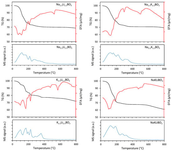
Figure 1.
TG/DTA profiles and corresponding mass signal of water (m/z = 18) for the studied samples (Na1.5Li1.5BO3, Na1.5K1.5BO3, K1.5Li1.5BO3, NaKLiBO3).
3.2. X-ray Diffraction
The diffraction patterns of the compounds investigated are gathered in Figure 2. The sample of H3BO3 consists of two crystalline phases: a H3BO3 triclinic majority phase (74.57 wt.%) (space group P-1 (No. 2), the lattice parameters: a = 7.018(3) Å, b = 7.035(1) Å, c = 6.547(2) Å, α = 92.49°, β = 101.46°, γ = 119.76°, strain of 0.012, and average crystallite size of 256 Å) and 25.43 wt.% of monoclinic secondary phase H2B12(OH)12 (space group P 1 21/n 1 (No. 14), lattice parameters: a = 8.570(2) Å, b = 8.203(3) Å, c = 8.465(2) Å, β = 90.14°, strain of 0.014, and average crystallite size of 202 Å). The sample, denoted as Na3BO3, consists of three crystalline phases: 59.1 wt.% of NaBO2·2H2O (sodium metaborate dihydrate, monoclinic, space group P 1 21/a 1 (No. 14), lattice parameters: a = 5.894(4) Å, b = 10.529(3) Å, c = 6.139(5) Å, β = 111.60°, strain of 0.025, and average crystallite size of 543 Å), 25.9 wt.% of Na2CO3 (monoclinic, space group C 1 21/m 1 (No. 12), lattice parameters: a = 8.885(3) Å, b = 5.240(2) Å, c = 6.040(2) Å, β = 101.20°, strain of 0.018, and average crystallite size of 525 Å), and 14.9 wt.% of Na3BO3 (monoclinic, space group P 1 21/c 1 (No. 14), lattice parameters: a = 5.663(4) Å, b = 7.409(1) Å, c = 9.964(3) Å, β = 127.07°, strain of 0.032, and average crystallite size of 429 Å). In Na1.5Li1.5BO3, carbonates of corresponding alkali metals are the majority crystalline phases, with a total amount of around 75 wt.%, and the average crystallite size calculated for the majority phase (monoclinic Na2CO3) is 537 Å, strain of 0.043. This sample also contains two borate-based crystalline phases: 8.7 wt.% of LiBO2·2H2O orthorhombic phase (space group P b c a (No. 61), lattice parameters: a = 9.155(3) Å, b = 7.679(3) Å, c = 8.377(4) Å, strain of 0.029, and average crystallite size of 585 Å) and around 16.3 wt.% of monoclinic NaBO2·2H2O (strain of 0.057, average crystallite size of 512 Å). The Na1.5K1.5BO3 sample consists mainly (92.8 wt.%) of potassium and sodium carbonates (the average crystallite size of carbonates was found to be around 354 Å) with a small amount (c.a. 7.8 wt.%) of NaBO2·2H2O. The NaKLiBO3 material comprises a considerable number of carbonates (43.3 wt.% with an average crystallite size of around 632 Å), as well as around 28.7 wt.% of NaBO2·2H2O and c.a. 23 wt.% of LiBO2·2H2O phases with crystallite sizes of 538 Å and 622 Å for the sodium and lithium phases, respectively. There are also traces of Li3BO3 (COD 2106065) and LiBO2 (COD 2310701) phases. It must be stressed, however, that most of the samples investigated exhibited both significantly attenuated overall signals as well as strong low-angle amorphous haloes, proving the high content of the amorphous phase.
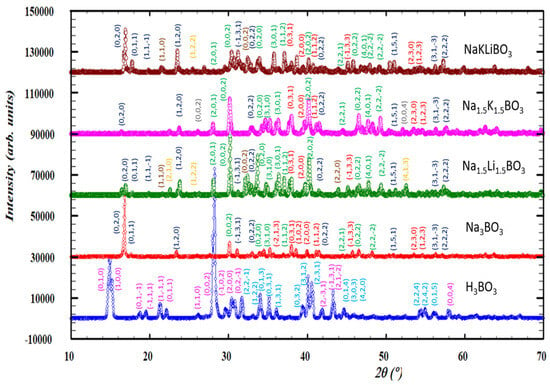
Figure 2.
Powder X-ray diffraction patterns for borate samples. CuKα, background corrected. The Miller indices for the crystalline phases identified for the studied samples are marked with different colors: triclinic H3BO3—pink indices; monoclinic H2B12(OH)12—light blue; monoclinic NaBO2·2H2O—dark blue; monoclinic Na2CO3—green; monoclinic Na3BO3—red; orthorhombic LiBO2·2H2O—orange; monoclinic Li2CO3—brown; monoclinic K2CO3—gray.
3.3. THz Spectroscopy
The additional spectroscopic verification [92] of the material synthesis was obtained using terahertz-range spectroscopy. Spectral images (see Figure 3) of substrate orthoboric acid (H3BO3), respective meta-(LiKB2O4) and tetra-(LiKB4O7) borates, as well as the best-performing electrolyte (Li1.5K1.5BO3), characterized both as just-obtained material and the specimen extracted from the dismantled cell after its use, prove not only the difference observed between the obtained orthoborate-based materials and both the substrate and the meta- and tetra-borate counterparts of the material investigated, but also that the carbonate-related contamination observed in the pristine orthoborate depicted with the absorption bands located at ~3.3 and 4.7 THz (band positions attributed according to [93]) vanishes in the operational conditions of the cell.
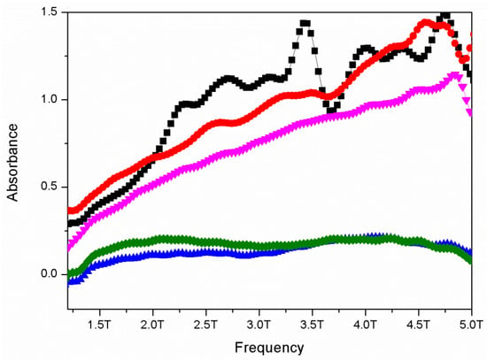
Figure 3.
THz TDS absorption spectra of H3BO3 (green), LiKB4O7 (cyan), LiKB2O4 (blue), just-synthesized Li1.5K1.5BO3 (black), and the specimen extracted from the dismantled cell (red).
3.4. FT-IR Spectroscopy
The broad band at 3400–2900 cm−1 with a visible peak at 3190 cm−1 is related to the –O-H stretching bonds of the –OH groups connected to boron (Figure 4, Table 2). Bands at 2507 cm−1, 2354 cm−1, 2263 cm−1, and 1736 cm−1 are to be interpreted as combination and overtone bands, according to Parson [94], specific to metaboric acid. The broad band found at 1403 cm−1 is related to the stretching of the B-O- bond [95], but the broadness of the band might also mask the ones related to the anti-symmetric stretching of the B-O- bonds. The bands at 699 cm−1 and 627 cm−1 are related to the stretching of the B-O- bond. It should be noted that the bands observed at 699 cm−1 and 627 cm−1 differ from those observed in the literature for orthoboric acid, suggesting that either the sample might contain metaboric acid rather than the ortho-counterpart or did not polymerize into more complex trimeric and tetrameric crystalline structures while being dried. The band visible at 879 cm−1 has been reported by Goubeau and Hummel [96] to be related to out-of-plane B-O- bond deformations. Some sources report that 710 cm−1 are related to BO3/BO4 bending vibrations, but the lack of other bands suggesting the presence of the polymerized BO4 structures puts that in doubt.
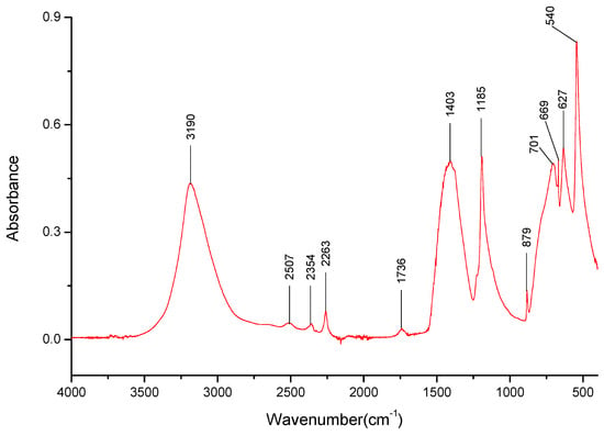
Figure 4.
FT-IR spectra gathered for the H3BO3 sample in the 4000–400 cm−1 range.

Table 2.
Bonds identified for the H3BO3 sample along with their respective wavenumbers.
The dried samples of three salts were also analyzed—Li3BO3, Na3BO3, and K3BO3. Firstly, bands matching the B-O-bonds that were identified at 1403 cm−1, 879 cm−1, 669 cm−1 for H3BO3 (Table 3) were identified for the three salts. The lack of the overtone band at 1736 cm−1 for the lithium salt spectra is also worth noting. However, it should be noted that the bands present around 1400 and 870 cm−1 were stronger than those observed for boric acid, especially around 870 cm−1, hinting that perhaps there is a significant amount of the respective carbonates present in the sample.

Table 3.
Identified positions and intensities of absorption bands (and their respective wavenumbers) for Li3BO3, Na3BO3, and K3BO3 samples. Bands related to the same bond are grayed out.
Unfortunately, there is a lack of literature in which the spectra of lithium, sodium, and potassium orthoborate salts are described. It could, perhaps, be assumed that the bands observed around 1200 cm−1 and 530 cm−1 could be related to cation interactions between them and the B-O- group, but it is hard to assay for this test.
It was determined that each of the salts exhibits specific absorption bands in the 3000–3500 cm−1 range (Figure 5, Figure 6 and Figure 7), the presence of which could later help identify the presence of specific cations in the mixed salt samples. Furthermore, the broadband present in that range suggests the presence of water, possibly in the form of hydrates. It should be noted that samples with the K+ cation had a broad band in the 3000–3500 cm−1 range (Figure 7), with only a few specific weak bands that could be identified within them.
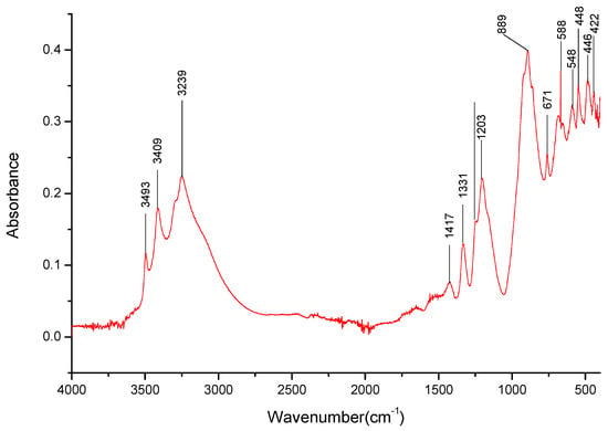
Figure 5.
FT-IR spectra gathered for the Li3BO3 sample in the 4000–400 cm−1 range.
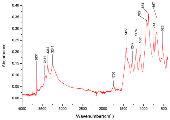
Figure 6.
FT-IR spectra gathered for the Na3BO3 sample in the 4000–400 cm−1 range.
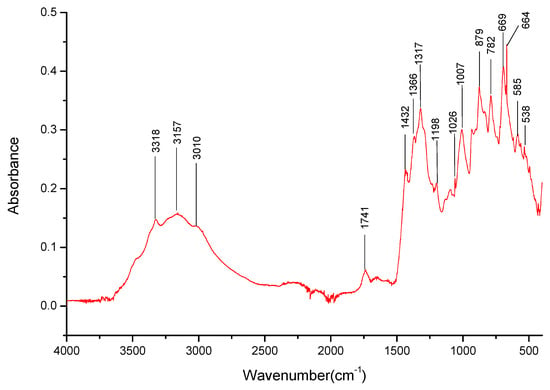
Figure 7.
FT-IR spectra gathered for the K3BO3 sample in the 4000–400 cm−1 range.
Due to the course of spectra analysis, it was determined that possibly all three salt samples were contaminated with their respective carbonates, although the source of the contamination is undetermined. This was due to detecting bands specific for the carbonates [97], some of which overlap bands of the B-O- groups (especially around 1400 cm−1, 880 cm−1). Due to this, it was decided that it would be better to identify the cations in the mixed cation salts by observing bands in the 3000–3500 cm−1 range rather than relying on bands in the 1500–700 cm−1 range. Spectra of 98% pure lithium, sodium, and potassium metaborates were collected to further identify the possibility of the carbonate presence in the sample (Figure 8, Figure 9 and Figure 10). It should be noted that both the sodium and potassium salts were available in hydrate forms, and, indeed, water was observable in a wide 3000–3600 cm−1 band. Once again, the bands at 1400 cm−1 and 870 cm−1 were present. However, for the sodium and potassium salts, the band found at 1400 cm−1 was weak in comparison to the strong one present in the boric acid sample. For lithium metaborate, a medium band could be observed instead. In the spectra registered for the metaborate salts, it was found that the 870 cm−1 band for both sodium and potassium was very strong, and for lithium, a medium one could be observed. While this, in part, confirms that these particular bands could relate to the B-O- bonds in the salts analyzed further, the bands can overlap with those of the respective carbonates, making the identification taxing. It can then be assumed, following the results from the XRD analysis, that carbonate presence negatively impacts the ability to properly analyze the samples using FTIR spectroscopy. It should also be noted that during the course of the experiments conducted on the lithium metaborates, it was observed that the exposure of a salt to air can cause carbonate pollution in its sample.
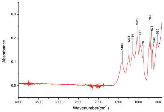
Figure 8.
FT-IR spectra gathered for the LiBO2 sample in the 4000–400 cm−1 range.
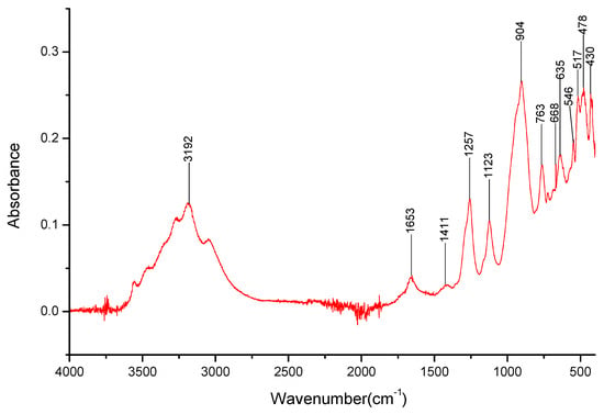
Figure 9.
FT-IR spectra gathered for the NaBO2 sample in the 4000–400 cm−1 range.
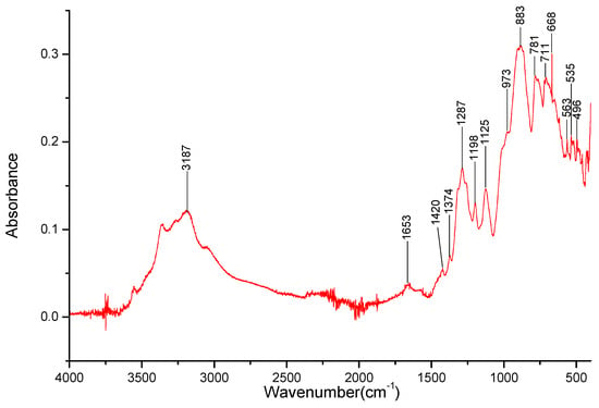
Figure 10.
FT-IR spectra gathered for the KBO2 sample in the 4000–400 cm−1 range.
For the Li1.5Na1.5BO3 (see Figure 11) salt, the bands for B-O- bond stretching and deformation are still observable at 1430 cm−1, 862 cm−1, and 670 cm−1, respectively (Table 4). Some of the bands in the 3200–3650 cm−1 range related to Na+ ions were found to overlap those of Li+, resulting in problems determining the presence of lithium cations in the salt. However, the broad band present in the 490–400 cm−1 range most likely contains bands related to the Li+ cation interactions.
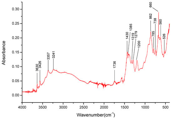
Figure 11.
FT-IR spectra gathered for the Li1.5Na1.5BO3 sample in the 4000–400 cm−1 range.

Table 4.
Identified positions and intensities of absorption bands (and their respective wavenumbers) for Li3BO3, Na3BO3, and L1.5Na1.5BO3 salt samples. Bands related to the same bond are grayed out.
For the K1.5Li1.5BO3 salt (see Figure 12), the disappearance of many bands specific to both cations is noteworthy; instead, there is a broad weak band present between 2490 and 3367 cm−1 (Table 5). The lack of the overtone observable at 1730 cm−1, hinting at the presence of Li+ cations, as observed in a previously analyzed salt, in addition to the broad, strong band in the 480–400 cm−1 range, should be noted. The bands for B-O- bond stretching and deformation are still observable at 1432 cm−1, 876 cm−1, and 664 cm−1, respectively.
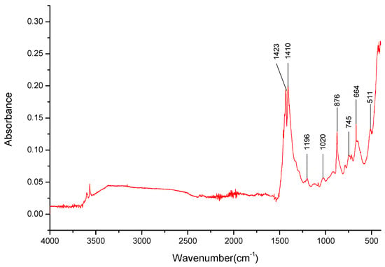
Figure 12.
FT-IR spectra gathered for the Li1.5K1.5BO3 sample in the 4000–400 cm−1 range.

Table 5.
Identified positions and intensities of absorption bands (and their respective wavenumbers) for Li3BO3, K3BO3, and Li1.5K1.5BO3 salt samples. Bands related to the same bond are grayed out.
The K1.5Na1.5BO3 (see Figure 13) salt exhibits a broad band in the 2490–3367 cm−1 range, possibly masking the bands related to K+ or Na+ cations. The bands for B-O- bond stretching and deformation are still observable at 1427 cm−1, 878 cm−1, and 667 cm−1, respectively, as well as the halftone present at 1736 cm−1; however, the band expected at 540 cm−1 is not visible in these spectra (Table 6).
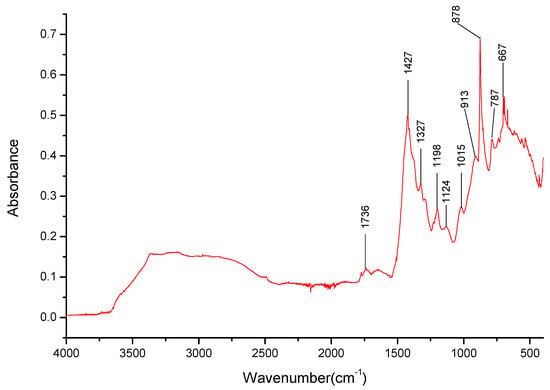
Figure 13.
FT-IR spectra gathered for the Na1.5K1.5BO3 sample in the 4000–400 cm−1 range.

Table 6.
Identified positions and intensities of absorption bands (and their respective wavenumbers) for Na3BO3, K3BO3, and K1.5Na1.5BO3 salt samples. Bands related to the same bond are grayed out.
In summary, the bands responsible for Na+ interactions with borate can be easily identified in the mixed cation salts. On the other hand, the bands related to Li+ interactions are harder to identify as they are muted in the mixed cation salt spectra. It is also worth noting that both salts containing K+ cations mixed with another cation exhibit a wide band between 2450 and 3600 cm−1, and the presence of said ion cannot be easily confirmed.
The LiNaKBO3 (Figure 14) exhibits absorption bands mostly associated with Na+ cation interactions in a borate salt—especially those in the 3000–3650 cm−1 range (Table 7). There was a lack of bands that could be associated with other cation interactions in that range. There was a broad, strong band in the 480–400 cm−1 range that could be associated with the presence of Li+ cations.
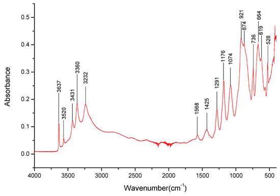
Figure 14.
FT-IR spectra gathered for the LiNaKBO3 sample in the 4000–400 cm−1 range.

Table 7.
Identified positions and intensities of absorption bands (and their respective wavenumbers) for Li3BO3, Na3BO3, K3BO3, and LiNaKBO3 salt samples. Bands related to the same bond are grayed out.
Some bands present in the mixed cation salts were matched in the 500–1500 cm−1 range with those present in the pure salts. But it should be stated that, as previously mentioned, due to the possible carbonate presence, these absorption bands might come from them, and it was impossible to identify them properly. Thus, based on the spectra, this specific sample stoichiometry might not be 1:1:1, as there is a lack of bands that could be associated with the potassium cations, while the presence of lithium and sodium cations could be confirmed.
It should be noted that for all the mixed cation salt samples, the spectra contained a wide band in the 3000–3650 cm−1 range, hinting at the possible formation of borate hydrates. Furthermore, the lack of bands associated with the trimers and tetramers in the mixed salt cation samples confirms the lack of borate polymerization in these samples, hinting at either the presence of ortho- or metaborate anions. The lack of the bands associated with BO3/BO4 bonds bending in the mixed cation salts, which are often a sign of borate crystalline structures, might also hint at an amorphous structure of the samples, confirming observations from the PXRD analysis.
4. Discussion
The IR spectra analysis of the precursor H3BO3 used for the borate salt synthesis hinted at the lack of typical polymerized borates, such as H2B4O7 (and higher), which are common products of boric acid dehydration, due to the lack of bands specific to them. This was further confirmed with an X-ray analysis, where, instead, the phase containing oxoacid H2B12(OH)12 was found. It is possible that the band for the sample found at 701 cm−1, which could not be matched to any of the bonds described in the literature, is a specific one related to this structure.
The synthesis of the borate salts performed using alkali hydroxides leads to the creation of highly hydrated amorphous structures. The presence of the hydrates was hinted by the DTA analysis, although it was difficult to determine the form of these hydrates. It should be stressed that the contamination of the samples with the respective carbonates (the source of which was undetermined) made the IR analysis extremely difficult, but certain bands that could be related to the Na+ and Li+ cations interacting with borate anions could be identified. This contamination was also confirmed by the X-ray analysis. Furthermore, the IR analysis confirmed the presence of water in the samples, either free or in the form of hydrates. The X-ray analysis did help to confirm that the water molecules were associated with the metaborate salts in the form of NaBO2·2H2O and LiBO2·2H2O.
It should be stressed that both analyses performed (IR and X-ray) could not detect potassium orthoborate or metaborate salts in the samples of more complex salts. The reason for this could not be determined at this time.
In conclusion, the alkali borate salt synthesis yielded a material with a high degree of amorphous phase—possibly a hydrated borate gel. This could be related to the usage of non-polymerized boric acid as a precursor, further evidenced by the lack of bands associated with tri- and tetramers, typical of polymerized boric acid. Instead, the presence of the identified oxoacid phase could have contributed to the qualities of the resulting synthesis product. In consequence, the micromorphology of the just-prepared sample of the best-performing K1.5Li1.5BO3 system (Figure 15a,b), its meta- (c) and tetra- (d) counterparts, as well as the sample of the same electrolyte (dispersed in the YSZ-based matrix) obtained by means of dismantling the previously working fuel cell (Figure 15f), significantly differs.
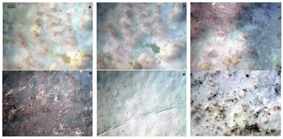
Figure 15.
Optical microscopy images of two specimens of the just-prepared sample of the K1.5Li1.5BO3 electrolyte (a,b), respective meta- (c) and tetra- (d) borates, the YSZ matrix used for fuel cell operation (e), as well as the orthoborate electrolyte dispersed in the YSZ matrix regained from the dismantled operational fuel cell (f). Artificially colored to increase the optical contrast of the images.
5. Conclusions
The possibility of their application as an electrolyte in a fuel cell with a construction like the molten carbonate fuel cell (MCFC) is a relatively new idea and has been preliminarily reported. Therefore, the extended phase-focused analysis of the materials applied was needed to re-optimize both the synthetic strategy (to further limit the contamination with carbonates) and the application route. Moreover, the optimization of the material composition can include the addition of di- and tri-valent cations, allowing for not only improvement of the operational properties of the melts but also to obtain the borane composite materials in which one of the present phases melts, forming the active electrolyte, while the other, characterized by a significantly higher melting temperature, forms the structural separator.
Moreover, it is worth noting that the electrolytes investigated bear the additional feature of increasing the sustainability and circularity of flue gas desulfation installations located in numerous hard coal-fired power plants, where boron can be extracted from industrial sewage. Results showed a complicated multi-phase structure, including the main orthoborate phase, as well as the presence of additional borate-based phases, including borate oxoacid. It should be noted, however, that the observed bands differ from those found in the literature for orthoboric acid, suggesting that either the sample might contain metaboric acid rather than the ortho-counterpart or did not polymerize into typical trimeric and tetrameric boric structures while being dried and, instead, polymerized into an oxoacid structure. A slightly contradictory image stems from the PXRD investigations showing the low content of the crystalline orthoborate phases. On the other hand, the DTA data hinted at the presence of the hydrated orthoborate phases, while the PXRD analysis revealed that these hydrates were of the metaborate kind instead.
Thus, it must be concluded that the expected orthoborate constituent is present in the materials in its amorphous and hydrated form. So, it was concluded that the synthesis resulted in the creation of a novel material in the form of an amorphous borate-based slurry. This material could, therefore, be easily applicable in fuel cells of designs like the MCFC ones.
Author Contributions
Investigation, A.K.-M., G.Ż., K.M., M.Z. and J.K.; Writing—original draft, P.R. and M.S.; Writing—review & editing, J.M., M.S. and J.K. All authors have read and agreed to the published version of the manuscript.
Funding
Studies were funded by POB Energy ENERGYTECH-1 (material synthesis) and ENERGYTECH-2 (spectroscopic investigations) projects granted by Warsaw University of Technology under the program Excellence Initiative: Research University (ID-UB).
Data Availability Statement
The original contributions presented in the study are included in the article, further inquiries can be directed to the corresponding authors.
Conflicts of Interest
The authors declare no conflict of interest.
References
- Ali, D.M.; Salman, S.K. A comprehensive review of the fuel cells technology and hydrogen economy. In Proceedings of the 41st International Universities Power Engineering Conference, Newcastle upon Tyne, UK, 6–8 September 2006; Volume 1, pp. 98–102. [Google Scholar] [CrossRef]
- Kordesch, K.V.; Simader, G.R. Environmental Impact of Fuel Cell Technology. Chem. Rev. 1995, 95, 191–207. [Google Scholar] [CrossRef]
- Thomas, J.M.; Edwards, P.P.; Dobson, P.J.; Owen, G.P. Decarbonizing energy: The developing international activity in hydrogen technologies and fuel cells. J. Energy Chem. 2020, 51, 405–415. [Google Scholar] [CrossRef]
- Chen, Q.; Zhou, J.; Qiu, P.; Lu, Y.; Huang, X.; Ding, C.; Ni, X. Research on the Model of Hydrogen Oxygen Fuel Cell. In Proceedings of the 2019 IEEE 3rd Conference on Energy Internet and Energy System Integration (EI2), Changsha, China, 8–10 November 2019. [Google Scholar] [CrossRef]
- Penconi, M.; Rossi, F.; Ortica, F.; Elisei, F.; Gentili, P.L. Hydrogen Production from Water by Photolysis, Sonolysis and Sonophotolysis with Solid Solutions of Rare Earth, Gallium and Indium Oxides as Heterogeneous Catalysts. Sustainability 2015, 7, 9310–9325. [Google Scholar] [CrossRef]
- Rabaey, K.; Verstraete, W. Microbial fuel cells: Novel biotechnology for energy generation. Trends Biotechnol. 2005, 23, 291–298. [Google Scholar] [CrossRef]
- Smitha, B.; Sridhar, S.; Khan, A. Synthesis and characterization of proton conducting polymer membranes for fuel cells. J. Membr. Sci. 2003, 225, 63–76. [Google Scholar] [CrossRef]
- Oh, K.; Ju, H. Temperature dependence of CO poisoning in high-temperature proton exchange membrane fuel cells with phosphoric acid-doped polybenzimidazole membranes. Int. J. Hydrogen Energy 2015, 40, 7743–7753. [Google Scholar] [CrossRef]
- Becker, H.; Murawski, J.; Shinde, D.V.; Stephens, I.E.L.; Hinds, G.; Smith, G. Impact of impurities on water electrolysis: A review. Sustain. Energy Fuels 2023, 7, 1565–1603. [Google Scholar] [CrossRef]
- Bergmann, A.; Gerteisen, D.; Kurz, T. Modelling of CO Poisoning and its Dynamics in HTPEM Fuel Cells. Fuel Cells 2010, 10, 278–287. [Google Scholar] [CrossRef]
- Haider, R.; Wen, Y.; Ma, Z.-F.; Wilkinson, D.P.; Zhang, L.; Yuan, X.; Song, S.; Zhang, J. High temperature proton exchange membrane fuel cells: Progress in advanced materials and key technologies. Chem. Soc. Rev. 2021, 50, 1138–1187. [Google Scholar] [CrossRef]
- Chin, D.T.; Howard, P.D. Hydrogen Sulfide Poisoning of Platinum Anode in Phosphoric Acid Fuel Cell Electrolyte. J. Electrochem. Soc. 1986, 133, 2447–2450. [Google Scholar] [CrossRef]
- Blum, L.; Deja, R.; Peters, R.; Stolten, D. Comparison of efficiencies of low, mean and high temperature fuel cell Systems. Int. J. Hydrogen Energy 2011, 36, 11056–11067. [Google Scholar] [CrossRef]
- Vishnyakov, V.M. Proton exchange membrane fuel cells. Vacuum 2006, 80, 1053–1065. [Google Scholar] [CrossRef]
- Lakshminarayana, G.; Nogami, M. Synthesis, characterization and electrochemical properties of SiO2–P 2O5–TiO2–ZrO2 glass membranes as proton conducting electrolyte for low-temperature H2/O2 fuel cells. J. Phys. D Appl. Phys. 2009, 42, 215501. [Google Scholar] [CrossRef]
- Wijayanta, A.T.; Oda, T.; Purnomo, C.W.; Kashiwagi, T.; Azizb, M. Liquid hydrogen, methylcyclohexane, and ammonia as potential hydrogen storage: Comparison review. Int. J. Hydrogen Energy 2019, 44, 15026–15044. [Google Scholar] [CrossRef]
- Eblagon, K.M.; Tam, K.; Tsang, S.C.E. Comparison of Catalytic Performance of Supported Ruthenium and Rhodium for Hydrogenation of 9-Ethylcarbazole for Hydrogen Storage Applications. Energy Environ. Sci. 2012, 5, 8621–8630. [Google Scholar] [CrossRef]
- Brückner, N.; Obesser, K.; Bösmann, A.; Teichmann, D.; Arlt, W.; Dungs, J.; Wasserscheid, P. Evaluation of Industrially Applied Heat-Transfer Fluids as Liquid Organic Hydrogen Carrier Systems. ChemSusChem 2014, 7, 229–235. [Google Scholar] [CrossRef]
- Xing, P.; Robertson, G.P.; Guiver, M.D.; Mikhailenko, S.D.; Wang, K.; Kaliaguine, S. Synthesis and characterization of sulfonated poly (ether ketone) for proton exchange membranes. J. Membr. Sci. 2004, 229, 95–106. [Google Scholar] [CrossRef]
- Lufrano, F.; Squadrito, G.; Patti, A.; Passalacqua, E. Sulfonated polysulfone as promising membranes for polymer electrolyte fuel cells. J. Appl. Polym. Sci. 2000, 77, 1250–1256. [Google Scholar] [CrossRef]
- Cha, M.S.; Lee, J.Y.; Kim, T.-H.; Jeong, H.Y.; Shin, H.Y.; Oh, S.-G.; Hong, Y.T. Preparation and characterization of crosslinked anion exchange membrane (AEM) materials with poly (phenylene ether)-based short hydrophilic block for use in electrochemical applications. J. Membr. Sci. 2017, 530, 73–83. [Google Scholar] [CrossRef]
- Adamski, M.; Peressin, N.; Holdcroft, S. On the evolution of sulfonated polyphenylenes as proton exchange membranes for fuel cells. Mater. Adv. 2021, 2, 4966–5005. [Google Scholar] [CrossRef]
- Ran, J.; Wu, L.; Ru, Y.; Hu, M.; Din, L.; Xu, T. Anion exchange membranes (AEMs) based on poly (2,6-dimethyl-1,4-phenylene oxide) (PPO) and its derivatives. Polym. Chem. 2015, 6, 5809–5826. [Google Scholar] [CrossRef]
- Itoh, T.; Hirai, K.; Tamura, M.; Uno, T.; Kubo, M.; Aihara, Y. Anhydrous proton-conducting electrolyte membranes based on hyperbranched polymer with phosphonic acid groups for high-temperature fuel cells. J. Power Sources 2008, 178, 627–633. [Google Scholar] [CrossRef]
- Hwang, K.; Kim, J.H.; Kim, S.Y.; Byun, H. Preparation of polybenzimidazole-based membranes and their potential applications in the fuel cell system. Energies 2014, 7, 1721–1732. [Google Scholar] [CrossRef]
- Asensio, J.A.; Sánchez, E.M.; Gómez-Romero, P. Proton-conducting membranes based on benzimidazole polymers for high-temperature PEM fuel cells. A chemical quest. Chem. Soc. Rev. 2010, 39, 3210. [Google Scholar] [CrossRef] [PubMed]
- Takamuku, S.; Jannasch, P. Multiblock copolymers with highly sulfonated blocks containing di- and tetrasulfonated arylene sulfone segments for proton exchange membrane fuel cell applications. Adv. Energy Mater. 2012, 2, 129–140. [Google Scholar] [CrossRef]
- He, Y.; Wang, J.; Zhang, H.; Zhang, T.; Zhang, B.; Cao, S.; Liu, J. Polydopamine-modified graphene oxide nanocomposite membrane for proton exchange membrane fuel cell under anhydrous conditions. J. Mater. Chem. A 2014, 2, 9548–9558. [Google Scholar] [CrossRef]
- Cao, L.; Sun, Q.; Gao, Y.; Liu, L.; Shi, H. Novel acid-base hybrid membrane based on amine-functionalized reduced graphene oxide and sulfonated polyimide for vanadium redox flow battery. Electrochim. Acta 2015, 158, 24–34. [Google Scholar] [CrossRef]
- Kim, S.; Hong, I. Effects of humidity and temperature on a proton exchange membrane fuel cell (PEMFC) stack. J. Ind. Eng. Chem. 2008, 14, 357–364. [Google Scholar] [CrossRef]
- Yang, C.; Srinivasan, S.; Aricò, A.S.; Cretì, P.; Baglio, V.; Antonucci, V. Composite Nafion/zirconium phosphate membranes for direct methanol fuel cell operation at high temperature. Electrochem. Solid-State Lett. 2001, 4, A31. [Google Scholar] [CrossRef]
- Adjemian, K.T.; Lee, S.J.; Srinivasan, S.; Benziger, J.; Bocarsly, A.B. Silicon Oxide Nafion Composite Membranes for Proton-Exchange Membrane Fuel Cell Operation at 80-140°C. J. Electrochem. Soc. 2002, 149, A256. [Google Scholar] [CrossRef]
- Krishnan, N.N.; Lee, S.; Ghorpade, R.V.; Konovalova, A.; Jang, J.H.; Kim, H.-J.; Han, J.; Henkensmeier, D.; Han, H. Polybenzimidazole (PBI-OO) based composite membranes using sulfophenylated TiO2 as both filler and crosslinker, and their use in the HT-PEM fuel cell. J. Membr. Sci. 2018, 560, 11–20. [Google Scholar] [CrossRef]
- Eguizábal, A.; Lemus, J.; Urbiztondo, M.; Garrido, O.; Soler, J.; Blazquez, J.A.; Pina, M.P. Novel hybrid membranes based on polybenzimidazole and ETS-10 titanosilicate type material for high temperature proton exchange membrane fuel cells: A comprehensive study on dense and porous systems. J. Power Sources 2011, 196, 8994–9007. [Google Scholar] [CrossRef]
- Kim, D.J.; Choi, D.H.; Park, C.H.; Nam, S.Y. Characterization of the sulfonated PEEK/sulfonated nanoparticles composite membrane for the fuel cell application. Int. J. Hydrogen Energy 2016, 41, 5793–5802. [Google Scholar] [CrossRef]
- Mossayebi, Z.; Saririchi, T.; Rowshanzamir, S.; Parnian, M.J. Investigation and optimization of physicochemical properties of sulfated zirconia/sulfonated poly (ether ketone) nanocomposite membranes for medium temperature proton exchange membrane fuel cells. Int. J. Hydrogen Energy 2016, 41, 12293–12306. [Google Scholar] [CrossRef]
- Devrim, Y.; Erkan, S.; Baç, N.; Eroǧlu, I. Preparation and characterization of sulfonated polysulfone/titanium dioxide composite membranes for proton exchange membrane fuel cells. Int. J. Hydrogen Energy 2009, 34, 3467–3475. [Google Scholar] [CrossRef]
- Wu, Y.; Wu, C.; Varcoe, J.R.; Poynton, S.D.; Xu, T.; Fu, Y. Novel silica/poly(2,6-dimethyl-1,4-phenylene oxide) hybrid anion-exchange membranes for alkaline fuel cells: Effect of silica content and the single cell performance. J. Power Sources 2010, 195, 3069–3076. [Google Scholar] [CrossRef]
- Inoue, T.; Uma, T.; Nogami, M. Performance of H2/O2 fuel cell using membrane electrolyte of phosphotungstic acid-modified 3-glycidoxypropyl-trimethoxysilanes. J. Membr. Sci. 2008, 323, 148–152. [Google Scholar] [CrossRef]
- Amirinejad, M.; Madaeni, S.S.; Rafiee, E.; Amirinejad, S. Cesium hydrogen salt of heteropolyacids/Nafion nanocomposite membranes for proton exchange membrane fuel cells. J. Membr. Sci. 2011, 377, 89–98. [Google Scholar] [CrossRef]
- Akbari, S.; Mosavian, M.T.H.; Moosavi, F.; Ahmadpour, A. Does the addition of a heteropoly acid change the water percolation threshold of PFSA membranes? Phys. Chem. Chem. Phys. 2019, 21, 25080–25089. [Google Scholar] [CrossRef] [PubMed]
- Motz, A.R.; Kuo, M.-C.; Horan, J.L.; Yadav, R.; Seifert, S.; Pandey, T.P.; Galioto, S.; Yang, Y.; Dale, N.V.; Hamrock, S.J.; et al. Heteropoly acid functionalized fluoroelastomer with outstanding chemical durability and performance for vehicular fuel cells. Energy Environ. Sci. 2018, 11, 1499–1509. [Google Scholar] [CrossRef]
- Lin, C.; Haolin, T.; Mu, P. Periodic Nafion-silica-heteropolyacids electrolyte t for PEM fuel cell operated near 200 °C. Int. J. Hydrogen Energy 2012, 37, 4694–4698. [Google Scholar] [CrossRef]
- Schmidt, C.; Glück, T.; Schmidt-Naake, G. Modification of Nafion Membranes by Impregnation with Ionic Liquids. Chem. Eng. Technol. 2008, 31, 13–22. [Google Scholar] [CrossRef]
- Rogalsky, S.; Bardeau, J.-F.; Makhno, S.; Tarasyuk, O.; Babkina, N.; Cherniavska, T.; Filonenko, M.; Fatyeyeva, K. New polymer electrolyte membrane for medium-temperature fuel cell applications based on cross-linked polyimide Matrimid and hydrophobic protic ionic liquid. Mater. Today Chem. 2021, 20, 100453. [Google Scholar] [CrossRef]
- Zanchet, L.; Trindade, L.G.; Bariviera, W.; Nobre Borba, K.M.; Santos, R.D.M.; Paganin, V.A.; Oliveira, C.P.; Ticianelli, E.A.; Martini, E.M.A.; de Souza, M.O. 3-Triethylammonium propane sulfonate ionic liquids for Nafion-based composite membranes for PEM fuel cells. J. Mater. Sci. 2020, 55, 6928–6941. [Google Scholar] [CrossRef]
- Kim, D.J.; Jo, M.J.; Nam, S.Y. A review of polymer–nanocomposite electrolyte membranes for fuel cell application. J. Ind. Eng. Chem. 2015, 21, 36–52. [Google Scholar] [CrossRef]
- Perry, M.L.; Fuller, T.F. A Historical Perspective of Fuel Cell Technology in the 20th Century. J. Electrochem. Soc. 2002, 149, S59–S67. [Google Scholar] [CrossRef]
- Sammes, N.; Bove, R.; Stahl, K. Phosphoric acid fuel cells: Fundamentals and applications. Curr. Opin. Solid State Mater. Sci. 2004, 8, 372–378. [Google Scholar] [CrossRef]
- Platonov, V.A. Properties of polyphosphoric acid. Fibre Chem. 2000, 32, 325–329. [Google Scholar] [CrossRef]
- Koo, J. Studies in Polyphosphoric Acid Cyclizations. J. Am. Chem. Soc. 1953, 75, 1891–1895. [Google Scholar] [CrossRef]
- Paschos, O.; Kunze, J.; Stimming, U.; Maglia, F. A review on phosphate based, solid state, protonic conductors for intermediate temperature fuel cells. J. Phys. Condens. Matter 2011, 23, 234110. [Google Scholar] [CrossRef] [PubMed]
- Joseph, L.; Tumuluri, A.; Klein, L.C. Progress in proton conducting sol-gel glasses. J. Sol-Gel Sci. Technol. 2022, 102, 482–492. [Google Scholar] [CrossRef]
- Hatada, N.; Toyoura, K.; Onishi, T.; Adachi, Y.; Uda, T. Fast and Anisotropic Proton Conduction in a Crystalline Polyphosphate. J. Phys. Chem. C 2014, 118, 29629–29635. [Google Scholar] [CrossRef]
- Herradon, C.; Le, L.; Meisel, C.; Huang, J.; Chmura, C.; Kim, Y.D.; Cadigan, C.; O’Hayre, R.; Sullivan, N.P. Proton-conducting ceramics for water electrolysis and hydrogen production at elevated pressure. Front. Energy Res. 2022, 10, 1020960. [Google Scholar] [CrossRef]
- Meng, Y.; Gao, J.; Zhao, Z.; Amoroso, J.; Tong, J.; Brinkman, K.S. Review: Recent progress in low-temperature proton-conducting ceramics. J. Mater. Sci. 2019, 54, 9291–9312. [Google Scholar] [CrossRef]
- Barelli, L.; Bidini, G.; Cinti, G.; Milewski, J. High temperature electrolysis using molten carbonate electrolyzer. Int. J. Hydrogen Energy 2021, 46, 14922–14931. [Google Scholar] [CrossRef]
- Milewski, J.; Szczęśniak, A.; Szablowski, L. A discussion on mathematical models of proton conducting solid oxide fuel cells. Int. J. Hydrogen Energy 2019, 44, 10925–10932. [Google Scholar] [CrossRef]
- Yuan, J.; Li, Z.; Yuan, B.; Xiao, G.; Li, T.; Wang, J.-Q. Optimization of High-Temperature Electrolysis System for Hydrogen Production Considering High-Temperature Degradation. Energies 2023, 16, 2616. [Google Scholar] [CrossRef]
- Wendt, H.; Imarisio, G. Nine years of research and development on advanced water electrolysis. A review of the research programme of the Commission of the European Communities. J. Appl. Electrochem. 1988, 18, 1–14. [Google Scholar] [CrossRef]
- Schober, T. Applications of oxidic high-temperature proton conductors. Solid State Ion. 2003, 162–163, 277–281. [Google Scholar] [CrossRef]
- Jiang, S.P. Functionalized mesoporous structured inorganic materials as high temperature proton exchange membranes for fuel cells. J. Mater. Chem. A 2014, 2, 7637–7655. [Google Scholar] [CrossRef]
- Aparicio, M.; Jitianu, A.; Klein, L.C. Sol-Gel Processing for Conventional and Alternative Energy; Springer US: Boston, MA, USA, 2012. [Google Scholar] [CrossRef]
- Kojima, S. Mixed-Alkali Effect in Borate Glasses: Thermal, Elastic, and Vibrational Properties. Solids 2020, 1, 16–30. [Google Scholar] [CrossRef]
- Kamistos, E.; Karakassides, M.A. Structural studies of binary and pseudo binary sodium borate glasses of high sodium content. Phys. Chem. Glas. 1989, 30, 19–26. [Google Scholar]
- Morey, G.W.; Merwin, H.E. Phase Equilibrium Relationships in the Binary System, Sodium Oxide-Boric Oxide, with Some Measurements of the Optical Properties of the Glasses. J. Am. Chem. Soc. 1936, 58, 2248–2254. [Google Scholar] [CrossRef]
- Zheng, L.; Sun, X.; Mao, R.; Chen, H.; Zhang, Z.; Zhao, J. Luminescence properties of Ce3+-doped lithium borophosphate glasses and their correlations with the optical basicity. J. Non-Cryst. Solids 2014, 403, 1–4. [Google Scholar] [CrossRef]
- Gerstenberger, D.C.; Trautmann, T.M.; Bowers, M.S. Noncritically phase-matched second-harmonic generation in cesium lithium borate. Opt. Lett. 2003, 28, 1242–1244. [Google Scholar] [CrossRef]
- Tran, B.H.; Wan, S.; Tieu, A.K.; Zhu, H. Tribological Performance of Inorganic Borate at Elevated Temperatures. Tribol. Trans. 2020, 63, 796–805. [Google Scholar] [CrossRef]
- Chryssikos, G.D.; Kamitsos, E.I.; Patsis, A.P.; Karakassides, M.A. On the structure of alkali borate glasses approaching the orthoborate composition. Mater. Sci. Eng. B 1990, 7, 1–4. [Google Scholar] [CrossRef]
- Polack, W.G. The anodic behavior of alkaline borate and perborate solutions. Trans. Faraday Soc. 1915, 10, 177–196. [Google Scholar] [CrossRef][Green Version]
- Calabretta, D.L.; Davis, B.R. Investigation of the anhydrous molten Na–B–O–H system and the concept: Electrolytic hydriding of sodium boron oxide species. J. Power Sources 2007, 164, 782–791. [Google Scholar] [CrossRef]
- Halliday, C. Molten Alkali Metal Borates for High Temperature Carbon Capture. Ph.D. Thesis, Massachusetts Institute of Technology, Cambridge, MA, USA, 2022. [Google Scholar]
- Martsinchyk, A.; Milewski, J.; Dybiński, O.; Szczęśniak, A.; Siekierski, M.; Świrski, K. Experimental investigation of novel molten borate fuel cell supported by an artificial neural network for electrolyte composition selection. Energy 2023, 279, 127921. [Google Scholar] [CrossRef]
- Milewski, J.; Szczęśniak, A.; Szabłowski, Ł.; Martsinchyk, A.; Siekierski, M.; Dybiński, O.; Świrski, K. Molten Borates Fuel Cells—Mathematical modeling and identification of performances. Renew. Sustain. Energy Rev. 2024, 190B, 113949. [Google Scholar] [CrossRef]
- Kamitsos, E.I.; Chryssikos, G.D. Borate glass structure by Raman and infrared spectroscopies. J. Mol. Struct. 1991, 247, 1–16. [Google Scholar] [CrossRef]
- Tran, B.H.; Tieu, K.; Wan, S.; Zhu, H.; Cuia, S.; Wang, L. Understanding the tribological impacts of alkali element on lubrication of binary borate melt. RSC Adv. 2018, 8, 28847–28860. [Google Scholar] [CrossRef]
- Saravanan, S.; Rajesh, S.; Palani, R. Thermal and Structural Properties of Mixed Alkali and Transition Metal Ions in Sodium Borate Glass. Int. J. Recent Res. Rev. 2015, 8, 1–9. [Google Scholar] [CrossRef]
- Youngman, R.E.; Zwanziger, J.W. On the Formation of Tetracoordinate Boron in Rubidium Borate Glasses. J. Am. Chem. Soc. 1995, 117, 1387–1402. [Google Scholar] [CrossRef]
- Vegiri, A.; Varsamis, C.-P.E.; Kamitsos, E.I. Composition and temperature dependence of cesium-borate glasses by molecular dynamics. J. Chem. Phys. 2005, 123, 014508. [Google Scholar] [CrossRef]
- Osipov, A.A.; Osipova, L.M. Structural studies of Na2O–B2O3 glasses and melts using high-temperature Raman spectroscopy. Phys. B Condens. Matter 2010, 405, 4718–4732. [Google Scholar] [CrossRef]
- Kononova, N.G.; Kokh, A.E.; Bekker, T.B.; Furmanova, N.G.; Maksimov, B.A.; Molchanov, V.N.; Fedorov, P.P. Growth and structure of barium sodium orthoborate NaBaBO3 crystals. Crystallogr. Rep. 2003, 48, 1044–1046. [Google Scholar] [CrossRef]
- Gałecki, J. Preparatyka Nieorganiczna—Czyste Związki Chemiczne; WNT: Warszawa, Poland, 1964. [Google Scholar]
- Supniewski, J. Preparatyka Nieorganiczna; PWN: Warszawa, Poland, 1958. [Google Scholar]
- Karki, A.; Feller, S.; Lim, H.P.; Stark, J.; Sanchez, C.; Shibata, M. The density of sodium-borate glasses related to atomic arrangements. J. Non-Cryst. Solids 1987, 92, 11–19. [Google Scholar] [CrossRef]
- Sennova, N.; Bubnova, R.S.; Cordier, G.; Albert, B.; Filatov, S.K.; Isaenko, L. Temperature-dependent Changes of the Crystal Structure of Li2B4O7. Z. Anorg. Allg. Chemie. 2008, 634, 2601–2607. [Google Scholar] [CrossRef]
- Marezio, M.; Remeika, J.P. Polymorphism of LiMO2 Compounds and High-Pressure Single-Crystal Synthesis of LiBO2. J. Chem. Phys. 1966, 44, 3348. [Google Scholar] [CrossRef]
- Levy, H.A.; Lisensky, G.C. Crystal structures of sodium sulfate decahydrate (Glauber’s salt) and sodium tetraborate decahydrate (borax). Redetermination by neutron diffraction. Acta Crystallogr. Sect. B 1978, 34, 3502–3510. [Google Scholar] [CrossRef]
- Fang, S.-M. The Crystal Structure of Sodium Metaborate Na3(B3O6). Z. Für Krist. Cryst. Mater. 1938, 99, 1–8. [Google Scholar] [CrossRef]
- Şahin, Ö.; Cennetkusu, E.S.; Dolaş, H.; Özdemir, M. Thermal decomposition of potassium tetraborate tetrahydrate to anhydrous potassium tetraborate in a fluidized bed. Thermochim. Acta 2006, 440, 7–12. [Google Scholar] [CrossRef]
- Zachariasen, W.H. The Crystal Structure of Potassium Metaborate, K3(B3O6). J. Chem. Phys. 1938, 5, 919. [Google Scholar] [CrossRef]
- Liu, X.; Liu, G.; Zhao, H.; Zhang, Z.; Wei, Y.; Liu, M.; Wen, W.; Zhou, X. The quantitative monitoring of mechanochemical reaction between solid l-tartaric acid and sodium carbonate monohydrate by terahertz spectroscopy. J. Phys. Chem. Solids 2011, 72, 1245–1250. [Google Scholar] [CrossRef]
- Sakai, S.; Yang, D.; Yasuda, T.; Akiyama, K.; Kuga, T.; Kano, A.; Shiraishi, F.; Amekawa, S.; Ohtsuka, S.; Nakaguchi, K.; et al. Pulsed Terahertz Radiation for Sensitive Quantification of Carbonate Minerals. ACS Omega 2019, 4, 2702–2707. [Google Scholar] [CrossRef]
- Parsons, J.L. Vibrational Spectra of Orthorhombic Metaboric Acid. J. Chem. Phys. 1960, 33, 1860–1866. [Google Scholar] [CrossRef]
- Amaravel, R. The Structural, Optical and Mechanical Properties of Sodium Borate Glasses. Int. J. Res. Appl. Sci. Eng. Technol. 2021, 9, 305–314. [Google Scholar] [CrossRef]
- Goubeau, J.; Hummel, D. Die Schwingungsspektren verschiedener Borsauerstoffverbindungen. Z. Phys. Chem. 1959, 20, 15–33. [Google Scholar] [CrossRef]
- Miller, A.; Wilkins, C.H. Infrared Spectra and Characteristic Frequencies of Inorganic Ions. Anal. Chem. 1952, 24, 1253–1294. [Google Scholar] [CrossRef]
Disclaimer/Publisher’s Note: The statements, opinions and data contained in all publications are solely those of the individual author(s) and contributor(s) and not of MDPI and/or the editor(s). MDPI and/or the editor(s) disclaim responsibility for any injury to people or property resulting from any ideas, methods, instructions or products referred to in the content. |
© 2024 by the authors. Licensee MDPI, Basel, Switzerland. This article is an open access article distributed under the terms and conditions of the Creative Commons Attribution (CC BY) license (https://creativecommons.org/licenses/by/4.0/).