1. Introduction
Under the current global decarbonization trend, the rapid development of hydrogen energy needs to be combined with the large-scale development and utilization of renewable energy sources, thus making the preparation of green hydrogen energy more and more popular. For example, renewable energy sources, such as solar and wind, are unstable and intermittent in the power generation process, making it challenging to apply these valuable electrical energy sources continuously and stably. To solve this problem, the utilization and stability of renewable energy sources can be significantly improved by using energy storage and conversion systems. The production of green hydrogen from waste photovoltaic and waste wind energy, which is then utilized in fuel cells to generate electricity, can be an essential means of smoothing out fluctuations in renewable energy, proton exchange membrane fuel cells (PEMFC) are increasingly gaining popularity in fixed power stations, energy storage devices, transportable power sources, automobiles, aviation, and various other applications due to their high energy conversion efficiency, pollution-free emissions, low operating temperature, and rapid start–stop capabilities [
1,
2,
3]. When hydrogen produces water through an electrochemical reaction, it releases thermal energy. Dealing with this heat is an essential challenge in PEMFC applications [
4,
5,
6].
Several scholars have proposed diverse methods to enhance the temperature control of fuel cells. Traditional control algorithms comprise proportional–integral control [
7], feedback control [
8], piecewise predictive negative feedback control [
9], and adaptive linear quadratic regulator feedback control [
10]. Nevertheless, owing to the intrinsic nonlinearity of PEMFC, these control algorithms exhibit limitations. Especially when the load changes dynamically and the system parameters are disturbed, a traditional control strategy will decrease the controller’s robustness.
Consequently, researchers aim to develop an algorithm compatible with nonlinear modes and introduce a series of novel control algorithms for regulating PEMFC temperature. These algorithms encompass model predictive control (MPC) [
11], fuzzy control, neural network control (NNC), and compound control. Compared to traditional designs, MPC stands out as a more fitting control algorithm. Several MPC algorithms regulate PEMFC temperature, including the model predictive control algorithm and robust feedback model predictive control [
12]. However, despite the high control accuracy advantage of the MPC algorithm, its effectiveness heavily relies on the precise modeling of PEMFC, a challenging task in practical implementation.
Some fuzzy-based control algorithms, including fuzzy control [
13], incremental fuzzy control [
14], and fuzzy incremental PID [
15], are employed for PEMFC temperature regulation. Additionally, multi-input, multi-output fuzzy control is utilized [
16]. However, despite being model-free with strong adaptability, these fuzzy-based control algorithms have overly simplistic fuzzy control rules. Consequently, their accuracy is insufficient for achieving precise adaptive control. As a model-free algorithm, NNC finds extensive application in fuel cell control, including artificial neural network control [
17] and BP neural network control [
18]. Nevertheless, despite its simple control principle, the performance of NNC exhibits substantial variations under different operating conditions. Due to the low robustness of the control algorithm based on neural networks, its performance exhibits significant variations under various operating conditions. In addition, due to the substantial interference and coupling in a temperature control system, Sun L Tan Chao and colleagues enhanced the temperature management of PEMFC by refining synovial film control [
19]. The results demonstrate that this approach significantly diminishes the temperature difference between the input and output cooling water of the reactor, enhancing the temperature control effectiveness.
However, many researchers currently choose to control circulating water pumps and radiators directly as separate components. Therefore, in the face of nonlinear and robust connection between a radiator and a circulating water pump, it is tough for researchers to decouple the controller from the algorithm.
The deep deterministic policy gradient (DDPG) algorithm is a widely employed deep reinforcement learning method in the control field [
20]. It approximates the update of a neural network’s weights by computing the gradient and estimating actions. This renders the DDPG algorithm effective for model-free multiple-in multiple-out (MF-MIMO) control [
21]. Therefore, in PEMFC fuel cell temperature control, a controller is used to control the pump and cooling fan in an integrated way. There is no need to decouple the two controllers; through the configuration of the reward function to achieve joint control of the pump and the fan, precise control of fuel cell temperature can be achieved. Nevertheless, traditional DDPG algorithms suffer from slow convergence, poor stability [
22], and the inability to accurately steer the training of PEMFC thermal management systems with lags and large inertia. We propose a deep deterministic policy gradient with priority experience playback and importance sampling method (PEI-DDPG) control method. In addition, we employ the Ornstein–Uhlenbeck (OU) stochastic process with inertial properties instead of zero-mean Gaussian noise to enhance the bootstrapping of inertial system training [
22]. To further enhance the model’s robustness and training speed, we use a Sumtree data structure to store empirically prioritized probability values. Additionally, a target smoothing strategy is introduced. These optimization methods enhance the algorithm’s robustness and achieve effective temperature control of the PEMFC.
The work of this paper is as follows:
Section 2 introduces the electric stack voltage of the fuel cell and the thermal management model of the fuel cell,
Section 3 introduces the temperature control theory based on the PEI-DDPG model,
Section 4 introduces the temperature control process of the fuel cell based on deep reinforcement learning,
Section 5 performs simulation validation of the proposed model, and
Section 6 performs validation of the proposed model in this paper on RT-LAB.
3. Temperature Control of PEMFC Based on Deep Reinforcement Learning Algorithm
This section presents a deep reinforcement learning-based framework for fuel cell temperature.
3.1. PEMFC Temperature Control Framework
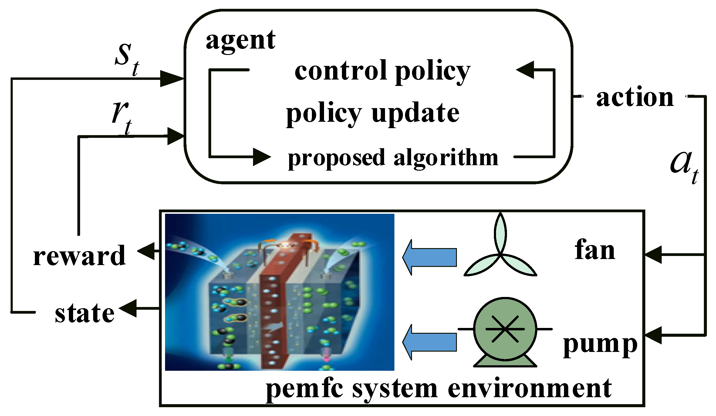
Agents continually interact with the environment to determine the best control approach to maximize the expected return value in the deep reinforcement learning-based temperature regulation of PEM fuel cells [
25]. It consists of a PEM fuel cell system environment, agent, state set S representing the environment, state A representing agent action, and reward R for an agent. The t-interaction process at a particular moment is shown in
Figure 1.
As depicted in
Figure 1, at time
, the PEM fuel cell system environment presents the observed system state
to the agent. The agent determines the cooling system action
using the deep reinforcement learning algorithm and the system state
. The environment updates the state at the next time step based on the action and provides a reward value
to the agent.
In this study, the PEMFC system serves as the environmental context. The actuator, consisting of a fan and water pump, constitutes the control variables. The control objective is to maintain the inlet temperature of PEMFC at 338.15 K through the coordinated operation of the radiator and circulating pump. Additionally, the desired change in the temperature difference between the inlet and outlet of PEMFC, , is set at 5 K.
3.2. State Space
The agent’s state space is ascertained:
The state-space parameters encompass the operational current () of the stack, the operational voltage () of the stack, the operational power () of the stack, the inlet temperature () of the stack, the outlet temperature () of the stack, the desired variation in temperature between the intake and output ( = 5), the target error in the inlet temperature ( = 0), the deviation between the temperature difference in the inlet and outlet and the target value (), and the deviation between the inlet temperature and the target value ().
3.3. Action Space
The PEMFC’s cooling air flow and cooling water flow make up the action space.
3.4. Reward Function
The
representation is stated in the form
when the termination condition (is done) is met.
The scale factor, K, and c must be tested and adjusted during training; this paper takes K = 0.13, and c takes a value of 1.51. The termination condition (is done) refers to when the reward function , exceeds a specific range and directly terminates the training.
3.5. Agent
The agent comprises deep reinforcement learning algorithms and their resultant control strategies. Deep reinforcement learning is categorized into three types: strategy learning, value learning, and actor–critic learning. The actor–critic approach amalgamates the merits of strategy learning and value learning, proficiently addressing the challenge of continuous action space, facilitating single-step updating, and enhancing learning efficiency. Because the state space and action space in the PEMFC temperature control problem involve continuous quantities, this paper uses the PEI-DDPG algorithm based on the actor–critic architecture.
4. PEI-DDPG Algorithm-Based PEMFC Temperature Regulation
This section describes the fuel cell temperature control process based on PEI-DDPG modeling.
4.1. Deep Deterministic Policy Gradient
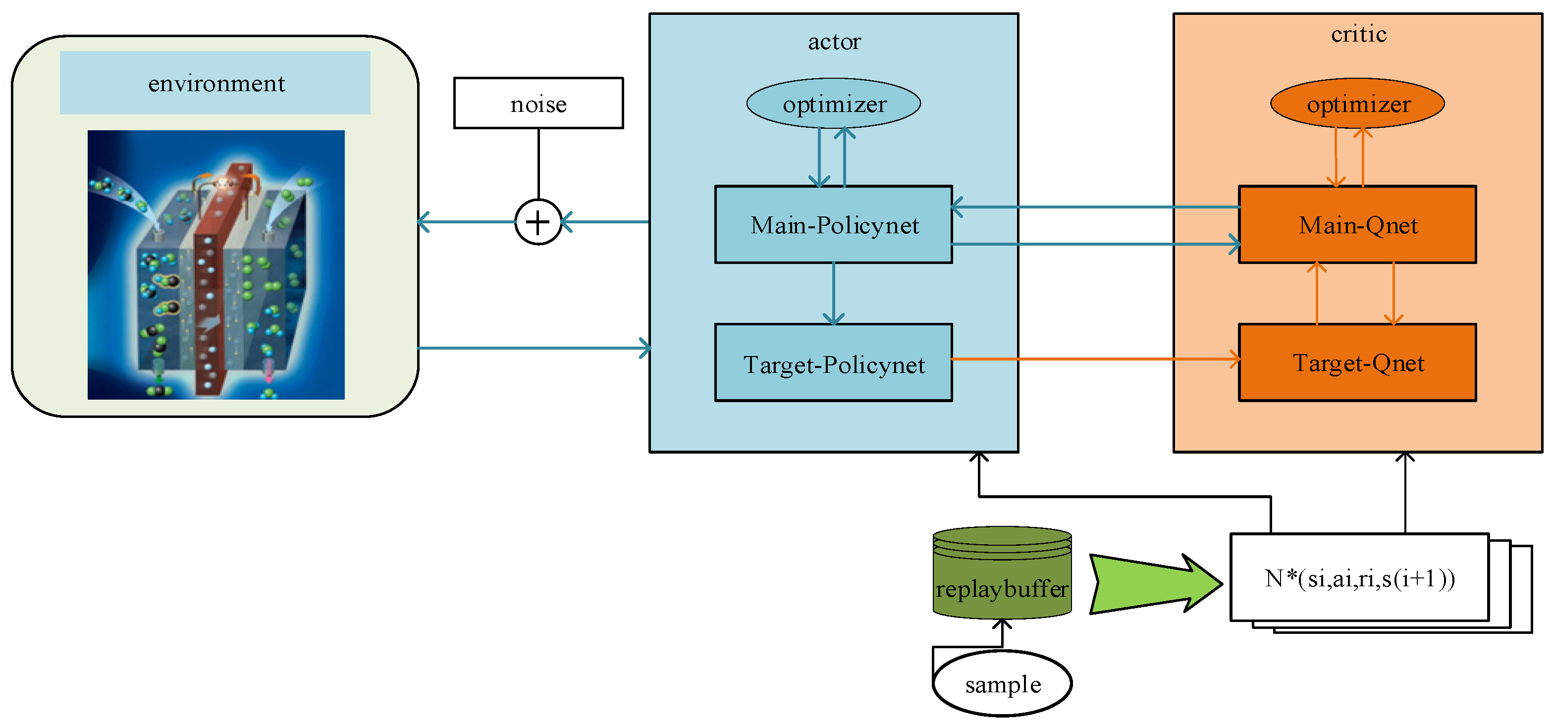
The deep deterministic policy gradient algorithm represents an enhancement and advancement of the actor–critic algorithm. The actor–critic algorithm can filter out random actions based on the learned strategy π within the continuous action space. However, the random strategy encounters slow network convergence and requires training data. Therefore, the random strategy gradient algorithm is replaced with the deterministic policy gradient algorithm, effectively addressing the issue of slow network convergence. Simultaneously, OffPolicy sampling is introduced to address the issue of unexplored environments [
26]. The actor network and the critic network are the two components of the DDPG algorithm. Main-PolicyNet and Target-PolicyNet make up the policy network, and Main-QNet and TargetQNet make up the value network. The specific structure is illustrated in
Figure 2.
We define
and
to represent the policy network function and value network function, respectively, where
and
denote the neural network parameters of Main-PolicyNet and Target-PolicyNet, respectively, and
and
denote the neural network parameters of Main-QNet and Target-QNet, respectively.
is updated by the gradient method, as in Equation (13),
is updated by minimizing the loss function, as in Equation (14), and
and
are updated using a soft method as shown in Equation (15).
In Equations (13) and (14), represents the number of samples. In Equation (14), is the output value of Target-QNet, and is the output value of Main-QNet. signifies the expected return at moment .
4.2. Priority Experience Playback
Policy optimization in reinforcement learning entails an approximate fitting process for various types of neural networks. Nevertheless, as a supervised learning model, deep neural networks demand independent and homogeneously distributed data. To address the instability associated with the traditional policy gradient method when integrated with neural networks, DDPG employs an empirical playback mechanism to eliminate correlations within the training data.
Experience playback comprises two components: storage sampling and experience sampling. In traditional empirical sampling, the agent utilizes incoming interactive data for training. During experience playback, the agent acquires interactive data, such as
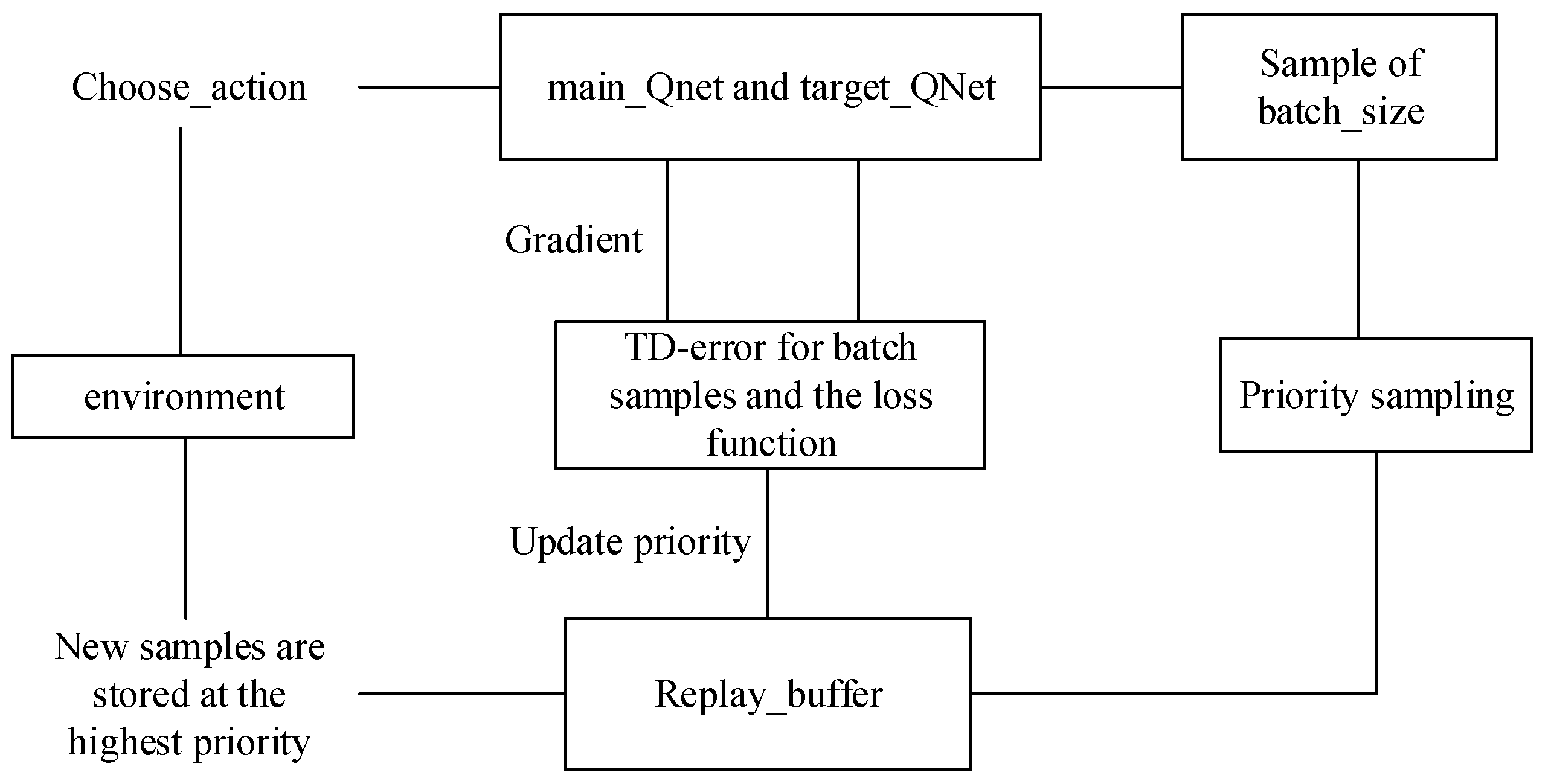
. These data are not directly employed for neural network training but are stored in the experience pool. Subsequently, batch experiences are extracted from the experience pool for training. The batch sampling of experience data from the buffer is termed experience playback. However, traditional empirical sampling and empirical playback employ uniform and random sampling as inefficient methods to utilize data. The proposed PER sampling strategy calculates the priority for each sample in the experience pool, enhancing the likelihood of valuable training samples. The principle of PER is illustrated in
Figure 3.
Because TD-error is usually used to update the action value function
in reinforcement learning, TD-error can implicitly reflect the learning effect of the agent from experience. This paper selects the absolute value |δ| of TD-error as the index to evaluate the experience value, as shown in Equation (16):
where
is as in Equation (14). The traditional DDPG algorithm employs random and uniform sampling, leading to significant fluctuations in the value of
. This results in poor training outcomes. Therefore, the sequential order of empirical data sampling during agent training becomes crucial in enhancing the algorithm’s performance. Consequently, Equations (17) and (18) delineate the procedures for empirical sampling and priority probability:
In Equation (17), when α equals 0, it represents uniform sampling. In Equation (18), represents the priority probability of the empirical value, and ∈ (0, 1) is introduced to prevent the unsampled from being 0. The larger is, the more positive the correction to the expected action value is, and the higher the corresponding priority probability is.
If each sample needs to be sorted according to the empirical probability, it will increase the computational complexity. Therefore, the Sumtree data structure is employed to store the empirical priority probability values. The specific structure is illustrated in
Figure 4, where the number of leaf nodes is denoted by “
”. Consequently, the total capacity of the Sumtree is
, and the samples are stored in the last layer of leaf nodes within the tree structure. Priority probability: The probability value
of each parent node in the leaf nodes equals the sum of the priority probabilities of all child node samples. Each leaf node corresponds to a unique index value, facilitating access to the corresponding samples using this index. The sample storage structure is depicted in
Figure 5.
When sampling, we divide the priority from 0 to
into n intervals, as shown in Equation (19), and randomly select a value
in each interval. Then, the corresponding leaf node is searched downward from the root node, and the sample data
stored in the corresponding leaf node are extracted. The search rule is as follows: assume that the randomly selected number is
, start the comparison from the root node, and if
, go to the right child node; if
, go to the left child node, but
, until you find the last leaf node.
4.3. Importance Sampling
In priority experience playback (PER), the absolute value of TD-error
is used as an index to evaluate whether the experience value is worth learning, and the experience is prioritized according to the magnitude of
. Experiences with high TD-error are frequently employed for training, leading to an inevitable alteration in state access frequency and causing oscillation or even dispersion in the neural network training process; thus, importance sampling (IS) is introduced. Importance sampling (IS) is introduced to ensure that samples have different probabilities of selection, guaranteeing that gradient descent yields consistent convergence results while simultaneously suppressing oscillations in the neural network training process. We define the importance sampling weight (ISW) as
, as represented in Equation (20).
where
represents the capacity of the empirical pool,
is defined as in Equation (17), and
is the weight coefficient controlling the degree of correction. As the training progresses, the weight coefficient gradually increases linearly to 1. When
equals 1, the impact of the PER on the convergence of the result is entirely nullified. To enhance convergence stability, Equation (20) undergoes normalization to yield Equation (21).
4.4. Exploration Noise of Ornstein–Uhlenbeck
Fuel cells have notable inertial working features. Hence, an Ornstein–Uhlenbeck (
OU) stochastic process—which is ideally suited for inertial systems—is used to describe the exploration noise [
27]. The noise produced by the OU process is shown as follows:
where
stands for the action state at time
,
for the work sampling data mean,
for the stochastic process learning rate,
for the
OU random weight, and
for the Wiener procedure to occur.
4.5. Delayed Strategy Updates
The actor network and the critic network in the conventional DDPG algorithm undergo successive parameter updates, exhibiting a specific correlation. However, errors in the critic network’s valuation can lead to suboptimal strategies. These less-than-ideal approaches magnify mistakes in the strategy network’s parameter update, causing it to update incorrectly and consequently training the critic network. This cyclic degradation between the two networks eventually results in deteriorating performance. By adding a target network, one can lessen the chance of overestimation-induced policy divergence, minimize errors from multi-step updates, and improve reinforcement learning stability. To do this, a strategy network that updates gradually offers the current value required to calculate the target network’s value. The value of the original network, however, is only used for strategy delay updates and action selection and parameter updates. This approach not only minimizes unnecessary and redundant updates but also mitigates the cumulative errors arising from multiple updates. Consequently, it helps to improve training stability and convergence as well as deal with the overestimation problem. A policy delay of two is assumed in the PEI-DDPG algorithm, meaning that the critic network receives two updates before the policy is modified.
4.6. Target Strategy Smoothing
Error propagation and accumulation can lead to a particular failure scenario in which an action’s estimated
Q value can rise unnecessarily high within a small range. The method may quickly exploit a peak that the
Q-function learns to be erroneous for an action, resulting in inaccurate actions. The research employs policy smoothing to mitigate this problem by seeking to reduce error production and improve the objective function’s smoothness. This is achieved by smoothing each dimension of analogous acts and adding noise to the objective policy network. To reduce notable fluctuations, a clip-clipping function is applied to the noise, limiting the maximum and minimum values of the output. In brief, the following is a description of the objective function:
Variance is reduced by smoothing the goal strategy, increases strategy update speed, boosts network stability, and speeds up learning by mitigating potential errors caused by the selection of particular aberrant peaks.
The PEI-DDPG algorithm (Algorithm 1) flow is as follows:
| Algorithm 1. PEI-DDPG. |
| 1: initialize the parameters and of the value network and the strategy network , and the replay_buffer capacity |
| 2: initialize the neural network parameters and of the target network |
| 3: initialize sampling probability and parameters and of IS weight, update frequency of target_Qnet neural network parameters updata_step, sampling batch bath_size |
| 4: for i = 1 to episode |
| 5: initialize state as the first state s of the current state set |
| 6: for = 1 to MAX_STEPS |
| 7: select new action according to new policy |
| 8: get and , store experience (, , , ) in replay_ buffer, and set = |
| 9: if ≥ updata_step and t%updata_every == 0 |
| 10: for to updata_every |
| 11: the sample obeys the empirical sampling probability Equation (17) |
| 12: calculate ISW: according to Equation (21), and calculate sample priority probability according to Equation (18) |
| 13: end for |
| 14: If mod policy_delay = 0, update critic network, update actor network |
| 15: end if |
| 16: end if |
| 17: end if |
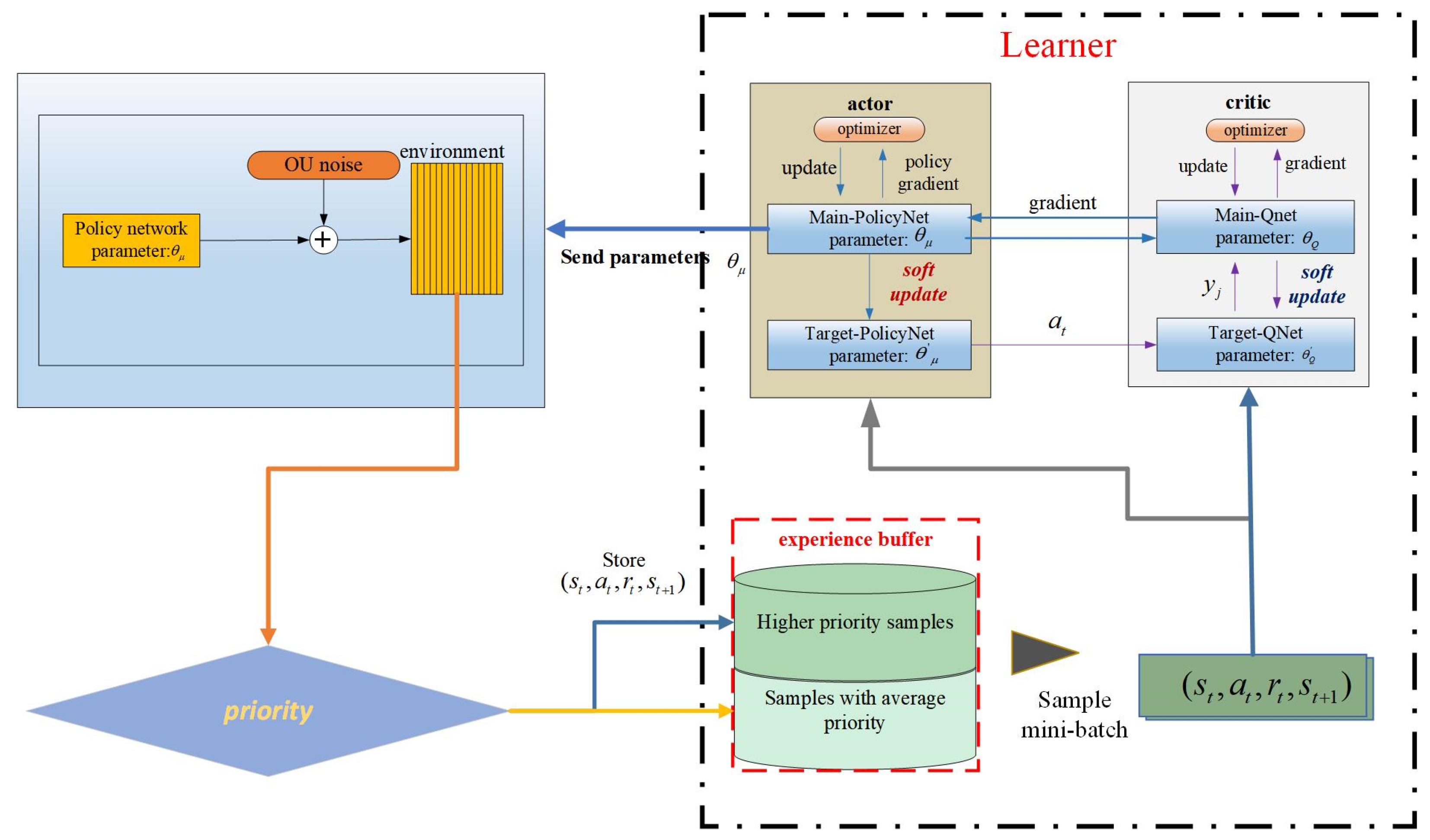
The PEI-DDPG-based PEMFC temperature control flowchart is shown in
Figure 6 5. Simulation Analysis
In this section, the simulation results of the PEI-DDPG model are analyzed under two operating conditions.
5.1. Simulation Conditions
Computer hardware specs for the simulation used in this paper include a 4.90 GHz 12th Gen Intel(R) Core(TM) i7-13620H CPU and 32 GB RAM. The simulation model that was used is the fuel cell temperature control system that was covered in the previous section.
Table 2 enumerates all of the key features of this system. The fuel cell temperature control system was implemented on the Simulink platform (version 2023a); MATLAB version 2023a was used for the simulation. The PEI-DDPG method’s performance was compared in the simulation to a number of algorithms, such as TD3 [
28] (twin delayed deep deterministic policy gradient), genetic algorithm-PID [
29], fuzzy PID [
30], DDPG, and PID.
5.2. Evaluation of Many Deep Reinforcement Learning Methods in Comparison
The simulations involved the selection of six different algorithms for comparison, among which PEI-DDPG, twin delayed deep deterministic policy gradient, and delayed deep deterministic policy gradient were categorized as deep reinforcement learning algorithms. To assess the performance of these algorithms, they were configured with identical parameters for both the training and testing phases, and their average reward values during training were subjected to comparison.
Figure 7 compares average reward values for the three deep reinforcement learning methods.
Analysis of
Figure 7 reveals that the PEI-DDPG algorithm demonstrates a more seamless and rapid learning process, achieving a higher maximum reward value compared to the DDPG and twin delayed deep deterministic policy gradient algorithms. In contrast, the DDPG and twin delayed deep deterministic policy gradient algorithms necessitate an extended learning period and manifest greater variability in their reward values. The PEI-DDPG algorithm integrates various technical enhancements, leading to improved exploration quality and accelerated convergence rates. The simulation results substantiate the efficacy of the PEI-DDPG algorithm in addressing the fuel cell temperature control challenge.
5.3. Temperature Control While Stepping Up the Load Current Continuously
The performance and training effectiveness of the PEI-DDPG algorithm are intricately linked to the architecture of the deep neural network, specifically the number of layers and neurons in each layer. In this specific instance, both the critic and actor networks are structured with three hidden layers, comprising 64, 32, and 16 neurons in each layer. The hyperparameters employed for the PEI-DDPG algorithm are detailed in
Table 3.
Following training, the simulation outcomes were contrasted with the outcomes of the DDPG, TD3, proportional–integral–derivative, genetic algorithm-PID, and fuzzy PID algorithms. The PEI-DDPG method’s performance was compared in the simulation to a number of algorithms, such as the twin delayed deep deterministic policy gradient, fuzzy PID, DDPG, and PID algorithms. The simulation results are illustrated in
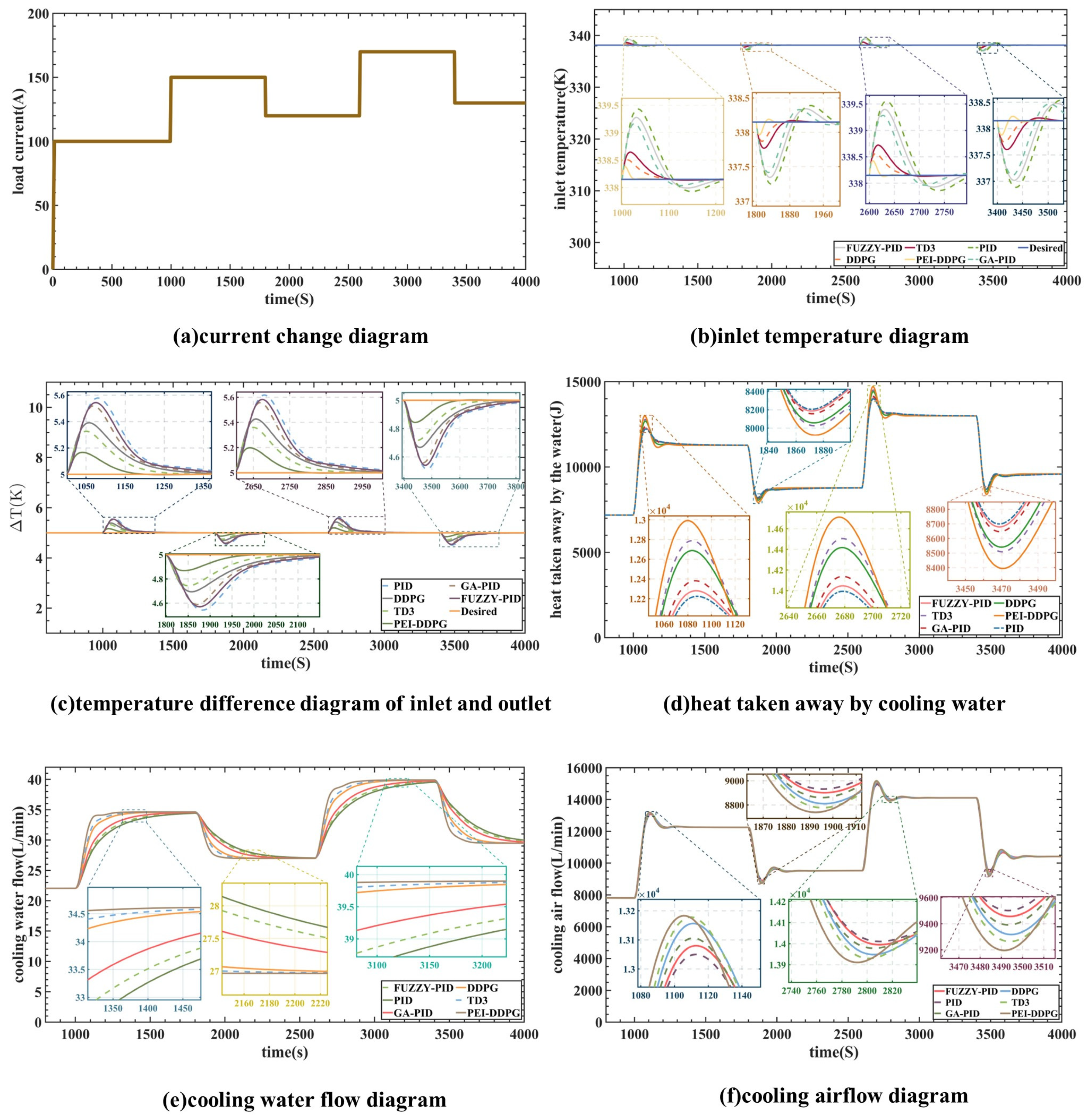
Figure 8. Panel (a) depicts the current changes in steps within the range of 100–170 A. The cooling water’s flow rate and heat transfer are shown in panels (e) and (d), respectively, while panel (f) displays the radiator flow-rate curve. At 1000 and 2600 s, the load increases, which prompts the PEI-DDPG controller to swiftly boost the water-pump flow and further dissipate heat from the stack. Similarly, when the load drops at 1800 and 3400 s, the PEI-DDPG controller quickly lowers the water pump’s flow rate, removing less heat from the stack. By efficiently controlling cooling liquid and airflow, the PEI-DDPG controller outperforms competing algorithms in terms of dynamic performance and response times.
Regarding intake water temperature regulation,
Figure 8b shows the outcomes of the DDPG, TD3, PEI-DDPG, genetic algorithm-PID, fuzzy PID, and PID algorithms. The PEI-DDPG algorithm shows significant improvements over the PID, DDPG, genetic algorithm-PID, fuzzy PID, and TD3 algorithms, with average control time reductions of 55.6 s, 108.4 s, 194.2 s, 257.9 s, and 288.7 s, respectively. In comparison to the genetic algorithm-PID algorithm and the TD3 method, the overshoot in the inlet temperature controlled by the deep deterministic policy gradient with priority experience playback and importance sampling method controller is decreased by 1.712 K and 0.263 K, respectively. The overshoot for the twin delayed deep deterministic policy gradient algorithm is about 0.3 K, but the overshoot for the genetic algorithm-PID method is limited to 0.5 K.
Figure 8e,f, at 2180 and 3100 s, demonstrates how quickly and consistently the suggested method responds to variations in load. In order to maintain the inlet temperature and temperature differential consistently around the reference value, the algorithm skillfully and reliably modifies the pump flow rate as well as the radiator flow rate.
The PEI-DDPG controller exhibits a distinct advantage over other controllers in managing the radiator power and cooling water flow rate to reduce overshoot and offset of and under varying load conditions. It demonstrates quicker response times in restoring to the reference value. Moreover, the PEI-DDPG algorithm efficiently handles the strong coupling between and , leading to enhanced control performance of both variables compared to traditional PID algorithms. The incorporation of various technical improvements into the PEI-DDPG algorithm has resulted in superior control effects when compared to TD3 or DDPG algorithms.
In comparison to alternative algorithms, the PEI-DDPG algorithm provides swifter response times and more precise control, leading to reduced overshoot. Following each parameter change, the DDPG controller effectively stabilizes at 5 K and at approximately 338 K, thereby ensuring the operational reliability of the PEMFC.
5.4. Temperature Control under Parameter Variation
The regulation of fuel cell temperature under steady-state 120 A load circumstances, with changes in anode inlet pressure, cathode inlet pressure, and water content, is covered in this section. We trained the PEI-DDPG with the same parameters as used in the previous section: training time, step size, and network architecture. The study’s hyperparameters are shown in
Table 4.
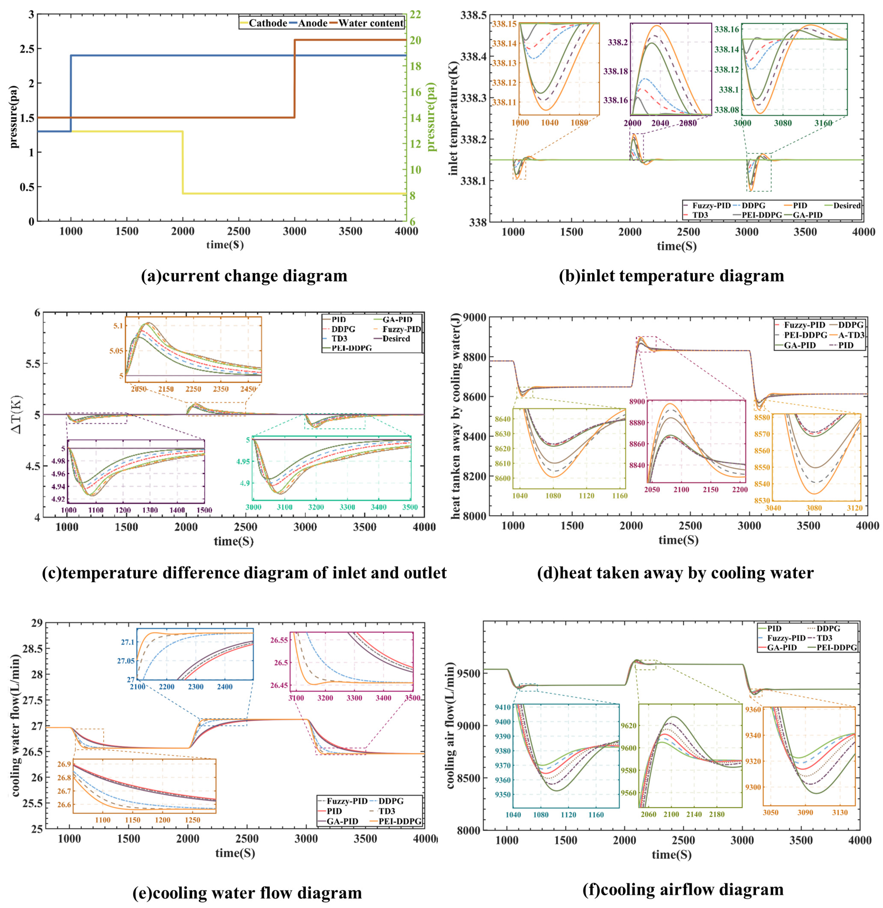
In this instance, the fuel cell current was stabilized at 120 A, as depicted in
Figure 9a. The testing signal duration was set to 1000 s. At the 2000 s mark, there was an increase in anode pressure from 1.3 atm to 2.4 atm. Simultaneously, at 3000 s, the water content of the proton exchange membrane rose from 14 to 20. Furthermore, at the 2000 s mark, the cathode pressure experienced a decrease from 1.3 atm to 0.4 atm.
At the 1000 s mark, there was an increase in anode pressure to 2.4 atm.
Figure 9e,f demonstrates the immediate response of the PEI-DDPG controller, adjusting the water pump and heat dissipation flow rate. This adjustment maintained the temperature difference and inlet temperature close to the reference value. At the 2000 s mark, there was a decrease in cathode pressure, followed by an increase in water content at 3000 s, leading to the same conclusion. Consequently, this illustrates the superior control performance of the PEI-DDPG controller. As depicted in
Figure 9d–f, when fuel cell parameters are changed, the PEI-DDPG algorithm outperforms other algorithms in terms of dynamic reaction and regulatory performance for managing the cooling airflow and circulation pump. This results in increased heat removal, leading to a more reasonable operating range for
and
. Furthermore, as shown in
Figure 9b, the PEI-DDPG algorithm-controlled
shows minimal overshoot when the model parameters are varied and can be promptly adjusted to the reference value. These results suggest that the PEI-DDPG algorithm exhibits greater robustness against diverse parameter variations than other controllers and consistently delivers superior control performance.
When comparing the results of the inlet temperature, , it is evident that the genetic algorithm-PID algorithm exhibits an overshoot up to 4.375 times greater than that of the deep deterministic policy gradient with priority experience playback and importance sampling method’s algorithm. Moreover, due to the high coupling between and , the PEI-DDPG joint controller significantly enhances the control performance of . When comparing the results of ∆T, it can be illustrated that the proportional–integral–derivative algorithm’s overshoot is twice that of the PEI-DDPG algorithm. In terms of controlling ∆T, the DDPG, TD3, and PEI-DDPG systems exhibit more efficient control than deep reinforcement learning algorithms. Despite being a joint control method for the thermal management system of PEMFC, PEI-DDPG improves significantly on its predecessor algorithms. It is better equipped to handle the system characteristics of PEMFC, rendering it more effective in controlling the thermal management system of PEMFC.
As illustrated in
Figure 9b–f, the PEI-DDPG joint control algorithm demonstrates the most efficient control performance, albeit with a slight overshoot compared to other algorithms. It can effectively and rapidly regulate the temperature difference within a range of approximately 5 K, thereby ensuring the fuel cell’s operational reliability. Furthermore, it was observed that the PEI-DDPG controller exhibits superior robustness compared to other controllers.
6. Experimental Verification
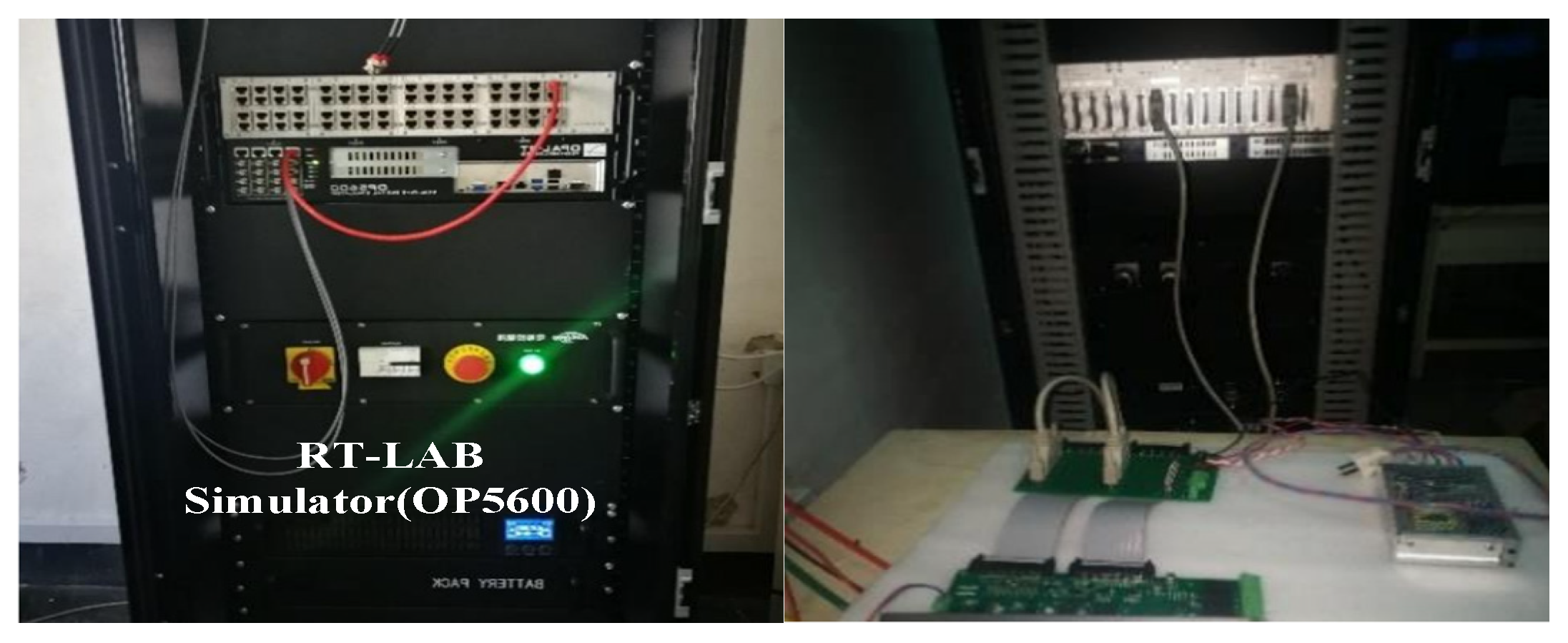
The experimental platform for hardware-in-the-loop testing, as illustrated in
Figure 10, comprises an RT-LAB real-time simulator, a DSP controller, and a monitoring computer. The proposed system implemented is a hardware-in-the-loop (HIL) system using OPAL-RT’s OP5600 real-time digital simulator (RTDS). The ADC of the OP5600 machine has a range of 0–10 V, so the sensed signals are scaled at this acceptable range. The step size of the simulation is set to 10 microseconds. The real-time simulation on RT-LAB consists of two subsystems: SM central and SC monitoring. The SC primary subsystem contains the FC power conditioning unit and SC monitoring system, which are accountable for transmitting the control signal to the SM primary subsystem [
31]. Also, it collects the observation in the central system and displays it in an oscilloscope to realize the real-time analysis. The experimental platform for hardware-in-the-loop testing, as illustrated in
Figure 10, comprises an RT-LAB real-time simulator, a DSP controller, and a monitoring computer. In
Figure 11, the fuel cell system undergoes conversion into C code, processed by the FPGA in the real-time simulator to generate corresponding analog signals. Subsequently, these analog signals are transmitted to the DSP controller for A/D sampling, leading to the formation of a digital signal. The control algorithm processes the digital signal to generate the control signal. Subsequently, the control signal undergoes conversion back to an analog signal through D/A conversion and is fed into the real-time simulator for real-time hardware-in-the-loop testing.
In
Figure 11, the fuel cell system undergoes conversion into C code, processed by the FPGA in the real-time simulator to generate corresponding analog signals. Subsequently, these analog signals are transmitted to the DSP controller for A/D sampling, leading to the formation of a digital signal. The control algorithm processes the digital signal to generate the control signal. Subsequently, the control signal undergoes conversion back to an analog signal through D/A conversion and is fed into the real-time simulator for real-time hardware-in-the-loop testing.
The control algorithm is programmed into the DSP chip of the RTU-BOX204 through a computer. It is crucial to note that the model parameters remain consistent with the simulation process outlined in the previous section during the entire testing process. To assess the hardware-in-the-loop system, experimental results were acquired by applying the load signal illustrated in
Figure 8a. The curves depicting the inlet temperature and temperature difference are shown in
Figure 12 and
Figure 13, respectively. The findings suggest that the PEI-DDPG controller demonstrates an excellent dynamic response with minimal overshoot. The PEI-DDPG controller showcases the optimal control effect, aligning with the simulation results.
7. Conclusions
With the use of a newly built fuel cell model and a deep reinforcement learning algorithm, this research presents a unique fuel cell temperature management approach called PEI-DDPG. This research investigates a PEMFC heat management system and presents a deep reinforcement learning-based temperature control algorithm (PEI-DDPG). By enhancing the initial algorithmic features, this technique improves the PEMFC thermal management system in many ways. It does this by substituting an agent that controls the radiator airflow rate and the pump’s cooling water flow rate, which were previously regulated separately, for the traditional control framework. The suggested temperature control method is assessed using continuous step changes in this current study. The findings of this study suggest that the PEI-DDPG controller outperforms other algorithms, such as the PID, genetic algorithm-PID, fuzzy PID, twin delayed deep deterministic policy gradient, and DDPG algorithms, in terms of resilience and control performance. From the experimental results, the proposed PEI-DDPG algorithm reduces the average adjustment time by 8.3%, 17.13%, and 24.56% and overshoots by 2.12 times, 4.16 times, and 4.32 times compared to the TD3, GA-PID, and PID algorithms, respectively. Experts’ advice is much appreciated. The suggested control scheme is evaluated in a variety of parameter circumstances, and the findings show that PEI-DDPG outperforms other comparative algorithms in terms of control and adaptability. Because of the algorithm’s adaptability and resilience, the PEMFC temperature is consistently controlled.
Although our PEI-DDPG temperature control strategy has been validated on simulation and hardware-in-the-loop testbeds, more complex real-world conditions, such as ambient temperature and humidity variations, equipment aging, etc., will be considered in future studies, and validation tests will be conducted on a PEMFC device to test and improve the adaptability and robustness of our algorithms for a wider range of more complex situations.
