Article

Analysis of Solar Radiation Differences for High-Voltage Transmission Lines on Micro-Terrain Areas

1
Xuefeng Mountain Energy Equipment Safety National Observation and Research Station, Chongqing University, Chongqing 400044, China
2
Chongqing Electric Power Design Institute Co., Ltd., Chongqing 404100, China
*
Author to whom correspondence should be addressed.
Energies 2024, 17(7), 1684; https://doi.org/10.3390/en17071684
Submission received: 11 March 2024 / Revised: 22 March 2024 / Accepted: 25 March 2024 / Published: 1 April 2024
(This article belongs to the Section F6: High Voltage)

Abstract

:
The stable operation of high-voltage transmission lines is significantly affected by atmospheric icing. Research on the physical processes of icing and de-icing of transmission lines in micro-terrain, as well as the factors affecting them, is a crucial theoretical foundation for enhancing current icing prediction capabilities and guiding the planning of transmission lines in mountainous areas. The difficulty lies in the fact that, unlike the calculation of surface radiation, the amount of radiation received by the lines is affected by a combination of terrain, environmental shading, and the orientation of the lines. Therefore, this work initially establishes a method for calculating the total amount of radiant heat received per unit length of the line throughout the day at various heights from the ground, based on the angle of solar incidence and the three-dimensional spatial position of the lines. Furthermore, a method of mapping the regional heat radiation by gridding the direction of the lines was proposed, providing the daily heat radiation and equivalent Joule heat. The proposed mapping method supports anti-icing planning for high-voltage transmission lines in micro-terrain areas.

1. Introduction

In recent years, widespread and long-distance transmission demands have inevitably led transmission lines to pass through micro-terrain areas. In these areas, local weather changes dramatically, making transmission lines more susceptible to collapse, breakage, and other accidents due to icing in adverse weather conditions, thereby affecting the security of the power system [1]. In adverse weather conditions, disturbances occur in the airflow field of micro-terrain areas, thereby affecting the magnitude of wind speed [2] and the spatial distribution of liquid water content in the air. In studies related to the impact of icing on transmission lines in micro-terrain areas, the solar radiation is typically considered to be zero [3,4], which is reasonable when the transmission lines are icing up. When the heat inflow into ice exceeds the outflow, the excess heat gradually raises the temperature of the ice to 0 °C, causing it to undergo a phase transition into liquid water. After adverse weather, solar radiation becomes an important heat source, affecting the heat balance process of the ice [5]. Li [6] proposes a scalable solar–thermal icephobic nanocoating that achieves effective deicing of transmission lines by increasing its absorption rate of solar radiation. There is relatively little research on the optical properties of ice on transmission lines. Frey [7] and Light [8] explore the impact of solar radiation on Arctic sea ice and prove the transmission of solar radiation through the ice layer is crucial for evaluating the heat and mass balance of sea ice.
However, the existing planning of transmission lines does not adequately consider the influence of terrain on the surface solar radiation of transmission lines.
Models for calculating solar radiation include on-site observation, remote sensing observation, and solar radiation models based on digital elevation models. On-site observation relies on data from observation stations. Based on terrain factors and the distribtion of observation stations, algorithms are used to obtain the distribution of solar radiation across the entire area. Ruiz-Arias [9] evaluates four up-to-date solar radiation models based on a digital elevation model (DEM); they were tested using a database provided by 14 radiometric stations. Akarslan [10] proposes five different new models for hourly solar irradiance forecasting. Solar data are measured and collected hourly to test the effectiveness of the proposed models. The prediction results indicated that the proposed models have good accuracy. Pang [11] examines a deep learning algorithm based on a recurrent neural network (RNN) for the prediction of solar radiation. This algorithm is designed to analyze actual meteorological data (AMY) obtained from a local weather station. Bailek [12] investigates the meteorological and radiometric data, encompassing variables such as the sunshine hour fraction (which represents the ratio of sunshine duration to maximum possible sunshine hours) and the relative clearness index and introduces a systematic method for estimating DSR (Direct Solar Radiation) over the Algerian Sahara. Feng [13] employs daily radiation and meteorological data gathered from 17 stations across China spanning from 1993 to 2015 and comprehensively assess 15 typical empirical models for estimating diffuse radiation across various climate zones within mainland China. Kambezidis [14] examined the fluctuations and trends in surface solar radiation levels over Athens during the period from 1992 to 2017. Dong [15] establish a novel convolutional neural network framework for solar irradiance prediction based on the Global Ensemble Forecast System. Feng [16] investigates a novel model for estimating global solar radiation, aiming to generate high-resolution solar radiation and photovoltaic power data over China. Wang [17] employs daily observations from 17 stations spanning from 1993 to 2015 to establish, test, and compare different models for predicting diffuse solar radiation in China. Peter [18] developed an algorithmic model for estimating radiation and humidity using temperature and precipitation data as inputs. The accuracy of this algorithm is dependent on the number and distribution of observation stations. To reduce reliance on observation stations, satellite remote sensing data has become a new data source. Bellaoui [19] uses satellite earth observation data to propose an alternative method for resource assessment. Wang [20] observed that complex terrain impacts the accuracy of estimating surface net solar radiation from high-resolution satellite remote sensing data. Zhang [21] quantifies the influence of complex topography to estimate incoming solar radiation using high-resolution satellite remote sensing data. Fibbi [22] proposed a new approach for predicting global solar radiation over rugged terrains but solar radiation estimates produced using this method are notably more accurate over horizontal surfaces. In desert regions of Northwest China, where meteorological stations are scarce, Yang [23] introduces a model that utilizes FY-4A satellite images to forecast global horizontal solar irradiance. Cornejo-Bueno [24] assesses the effectiveness of various machine learning regression techniques in estimating global solar radiation from geostationary satellite data. The results obtained show the capacity of machine learning to obtain reliable global solar radiation. Bright [25] offers an impartial and unbiased validation of the historical global horizontal irradiance dataset provided by the solar resource assessment and forecasting company. Doorga [26] introduces a novel hybrid forecasting tool that leverages satellite remote sensing data of surface solar irradiation. The mean absolute percentage error of this hybrid system is reported to be the lowest (4.89%) on average for five-consecutive-days-ahead forecasts spanning the years 2013–2015. Ghimire [27] endeavors to identify an effective data-driven machine learning model for predicting the monthly daily average solar radiation using meteorological datasets obtained from Giovanni (Satellite). Zhang [28] put forward a solar radiation model based on the MODIS remote sensing dataset, which is suitable for mountainous areas where observation stations are scarce. Wang [29] employed an artificial neural network model in conjunction with remote sensing data and TOA radiation to estimate solar radiation, subsequently refining the estimates through terrain factors. Liu [30] employed the remote sensing-based Heliosat-2 model and the Angstrom-Prescott regression model, which relies on sunshine duration, across various-resolution digital elevation models. Due to the scarcity and difficulty in obtaining on-site observation data, satellites that regularly measure remote sensing data can serve as a powerful supplement. They provide satisfactory accuracy in predicting solar radiation in specific regions. However, these methods focus on surface solar radiation and do not take into account various buildings on the surface. For various facilities on the surface, a solar radiation model based on digital elevation models is a better choice. Dozier [31] presents a rapid approach for computing the slope, azimuth, solar illumination angle, horizons, and view factors concerning radiation from both the sky and terrain using digital elevation models. Dubayah [32] summarizes the integration of solar radiation models into GIS and their implications on solar radiation due to topography and plant canopies. As distributed energy technology [33,34] becomes increasingly prevalent, there is a growing need for methodologies to assess solar potential on multiple building rooftops. This can be achieved through the implementation of the upward-looking hemispherical viewshed algorithm or pixel-based models. Hong [35] introduced a technique for estimating the potential of rooftop solar photovoltaic (PV) installations using Hillshade analysis. This method relies on the orientation of buildings to identify shadows but does not account for shadows caused by building shading. Tscholl [36] and Chen [37] investigate the impact of different scale grids on the prediction results of solar radiation on complex terrain. Upon completing the solar position chart, viewshed map [38], and surface shape of the facilities, direct and scattered radiation within a certain period can be obtained. Photovoltaic power generation, as an important renewable energy source. Xu [39] and Gardashov [40] discovered that terrain features can induce shading effects on sunlight, impacting the efficiency of photovoltaic power generation. They introduced viewshed maps as a tool to identify the most suitable locations for installing photovoltaic devices in complex terrain.
In this study, a solar radiation model based on digital elevation models is used to calculate the differences in ice melting caused by the terrain in micro-terrain areas on ice-covered transmission lines. The contributions of this paper include (i) establishing a method for calculating solar radiation on transmission lines at a certain height above the ground; (ii) fully considering the influence of terrain variations in micro-terrain areas on the surface solar radiation of transmission lines; (iii) converting solar radiation into differences in ice melting, providing certain reference value for the subsequent planning of transmission lines in micro-terrain areas.

2. Solar Radiation Calculation Method for Transmission Lines Based on DEM

2.1. Calculation of Solar Position
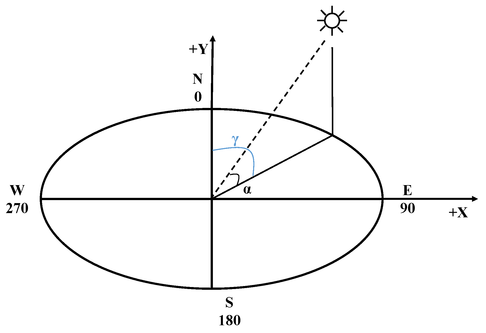
The movement of the sun has a significant impact on the solar irradiance received by surfaces on the Earth’s surface and nearby objects. When sunlight is perpendicular to a surface, the power absorbed by the surface equals the direct solar irradiance. As the angle between the sun and the surface changes, the power absorbed by the surface decreases. When the sunlight is parallel to the absorbing surface, the absorbed power is zero. The position of the solar is shown in Figure 1. The angle between the sun and a fixed location on Earth depends on the latitude and longitude of that location, the day of the year, and the time of day. The altitude angle α is the angular height of the sun measured from the horizontal plane in the sky. It is 0° at sunrise and 90° when the sun is directly overhead. The corresponding angle is the zenith angle ζ, and the sum of the two angles is 90°. The azimuth angle γ is the horizontal angle from the north direction clockwise to the direction of the sun’s incidence.
α = sin 1 [ sin δ sin φ + cos δ cos φ cos ( H R A ) ]
γ = c o s 1 [ s i n δ c o s φ c o s δ s i n φ c o s ( H R A ) c o s α ]
ζ = 90 α
In which, δ represents the declination angle, depending on the day of the year; φ represents latitude; HRA represents the hour angle.
Figure 1. Solar position.
Energies 17 01684 g001

2.2. Viewshed Calculation

Solar radiation originating from the sun passes through the atmosphere and is influenced by terrain and other surface features, being decomposed into direct, scattered, and reflected components. Generally, direct radiation is the largest component of total radiation, while scattered radiation is the second largest component. Radiation reflected from the surrounding terrain features to a location typically only accounts for a small fraction of the total incident radiation and can be considered negligible. Scattered radiation can be considered as uniformly coming from all parts of the sky. The sky is divided into multiple sky sectors, and the scattered radiation from each unobstructed sector is considered as direct radiation emitted from the center of that sector. The total scattered radiation is obtained by summing the scattered radiation emitted from each sky sector. Figure 2 shows 48 uniformly spaced azimuth angle divisions and 9 uniformly spaced zenith angle divisions [41].
As shown in Figure 3, the terrain in micro-terrain areas is uneven. Along the direction of sunlight, larger mountains can block smaller ones behind them. When the transmission line is located on the smaller mountains, the direct component received on the conductor surface will become zero due to shading, while the scattered component can be considered as uniformly coming from all parts of the sky, with its magnitude depending on the size of the visible sky.
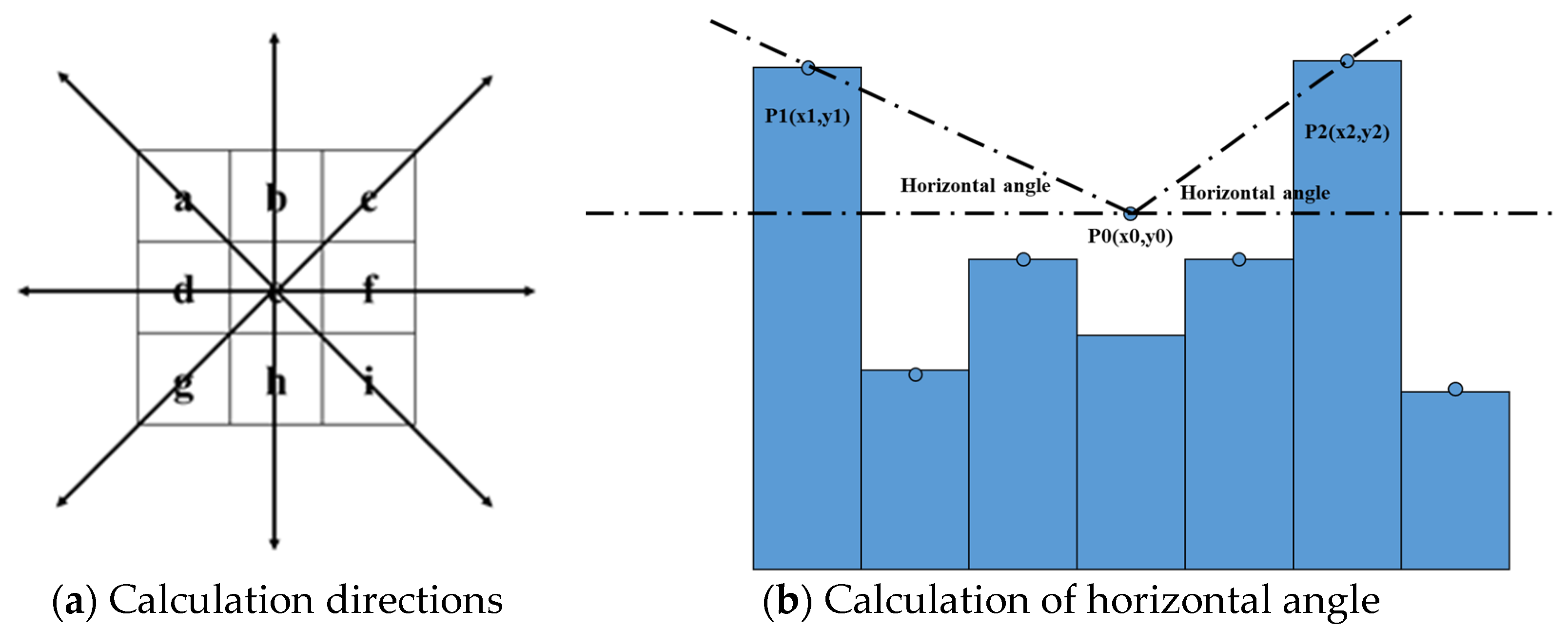
The viewshed map reflects a situation where the sky is obscured by the terrain when looking up from the ground. Therefore, one of the key steps in radiation calculation models is to compute the viewshed map of the location of interest in the terrain. As shown in Figure 4a, the study location is set as the origin. In the specified number of directions around it, the angle between each point and the origin with the horizontal plane is continuously calculated in each search direction. The maximum angle is defined as the maximum horizontal angle [31]. When the sun is in that direction and the altitude angle is lower than the maximum horizontal angle, direct solar radiation from the sun will be blocked. Since scattered radiation is assumed to come from every direction in the sky, it will also be affected.
As shown in Figure 4b, P0 is the observation point, and the maximum horizontal angles occur between the observation point P0 and points P1 and P2 on both sides. If the solar altitude angle is greater than the maximum horizontal angle at a specific point, it is considered that the direct solar component received at that point will not be obstructed by the terrain.
Horizontal   angle = tan 1 ( y 2 y 0 x 2 x 0 )
f h i d e = 1 α > Horizontal   angle 0 α < Horizontal   angle
The shading effect of terrain can be divided into its impact on direct radiation and its impact on scattered radiation. When the solar altitude angle is lower than the maximum horizontal angle, it is equivalent to being below the horizon, and the direct radiation is zero. Scattered radiation is considered to come from point sources in all sky sectors, and terrain-induced shading will also obstruct some of the scattered radiation. Overlaying the viewshed map and the solar position map facilitates the calculation of direct and scattered radiation from every direction in the sky. Some portions of the solar map are obstructed. When calculating scattered radiation, the proportion of unobstructed sectors needs to be computed to correct the scattered radiation amount. The viewshed map and solar position map are overlaid to calculate direct and scattered radiation from every direction in the sky. For points at a certain height above the ground, there is no slope and gradient. The shading coefficient is defined as the ratio of the solar radiation flux considering terrain shading to the solar radiation flux without considering terrain shading.
f s h a d e = Q r e c e i v e d Q a l l

2.3. Direct and Scattered Radiation Flux

For points at a certain height above the ground, the direct radiation flux is calculated based on the position of the sun, atmospheric attenuation, and terrain shading conditions. The total daily radiation can be obtained by summing up the radiation calculated for each time interval throughout the day.
Q s u n D i r = f h i d e Q s u n c o n s t β m ( ζ ) Δ t
Qconst represents the solar intensity outside the Earth’s atmosphere, which can be considered constant. β is the transmittance of the shortest path of sunlight through the atmosphere; this value is typically 0.5 under clear-sky conditions. fhide is the shading coefficient, which is 0 when the location is shaded by terrain and 1 when there is no terrain shading. m(ζ) represents the relative optical path length. When sunlight does not enter from the zenith direction, the path through the atmosphere will be longer, determined by the zenith angle ζ and the altitude z. For zenith angles greater than 80°, atmospheric refraction of solar radiation becomes significant and needs to be corrected.
m ( ζ ) = e ( 0.000118 z 1.638 10 9 z 2 ) cos ( ζ )
Scattered radiation originates from the centroid of each sky sector. Each centroid is treated as a point source of radiation, and the calculation method is the same as for direct radiation.
Q S u n D i f f = f h i d e f w e i g h t Q S u n c o n s t P D i f f 1 P D i f f β m ( ζ )
f w e i g h t = cos ζ 2 cos ζ 1 N
Q S u n = ( Q S u n D i r ( ζ ) + Q S u n D i f f ( ζ ) )
PDiff represents the proportion of scattered radiation. Under clear sky conditions, this value is typically 0.3. z is the altitude, and N is the number of azimuthal divisions. fweight represents the weight of each sector.

2.4. Radiative Flux on Transmission Line Surface

To avoid defining the shape of the transmission lines based on the slope and orientation of the ground, points are established at regular intervals on the DEM, each at the same height above the ground. A transmission line is determined by connecting adjacent points, and four transmission lines form a grid. The transmission line is considered as a straight line. When there is a height difference between adjacent points, an angle is formed between the transmission line and the horizontal plane. This angle is independent of the terrain variations along the route. However, in studies related to solar radiation on the ground, the solar radiation at each point is influenced by both the slope and aspect of the terrain. The position of the sun is defined by the azimuth angle and the zenith angle. The direct radiation component is decomposed into two components: one from the direction of the zenith angle at 0° and the other from the direction of the azimuth angle. The scattering component for each sector is decomposed using the same method. For transmission lines of any orientation, the actual received radiation is corrected using the coefficient fAngle.
f a n g l e = ( sin ( α ) cos ( a n g l e ) ) 2 + ( cos ( α ) cos ( a n g l e ) sin ( γ o r i e n t a t i o n ) ) 2 + ( cos ( α ) sin ( a n g l e ) ) 2
Formulas (7) and (9) can be written as follows:
Q s u n D i r = f a n g l e f h i d e Q s u n c o n s t β m ( ζ ) Δ t
Q s u n d i f f = f a n g l e f h i d e f w e i g h t Q a u n c o n s t P d i f f 1 P d i f f ( β m ( ζ ) )
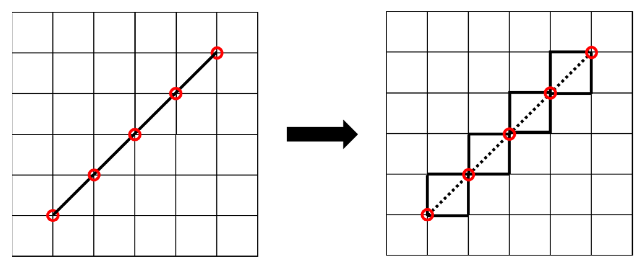
As shown in Figure 5, the solar radiation received by the transmission line oriented at 45° is calculated using the following method. Assuming that within the study map area, sunlight is parallel, and at any given moment, the direction of sunlight is the same for each point. Transmission lines oriented in the north–south direction are considered at 0°, while those in the east–west direction are considered at 90°.
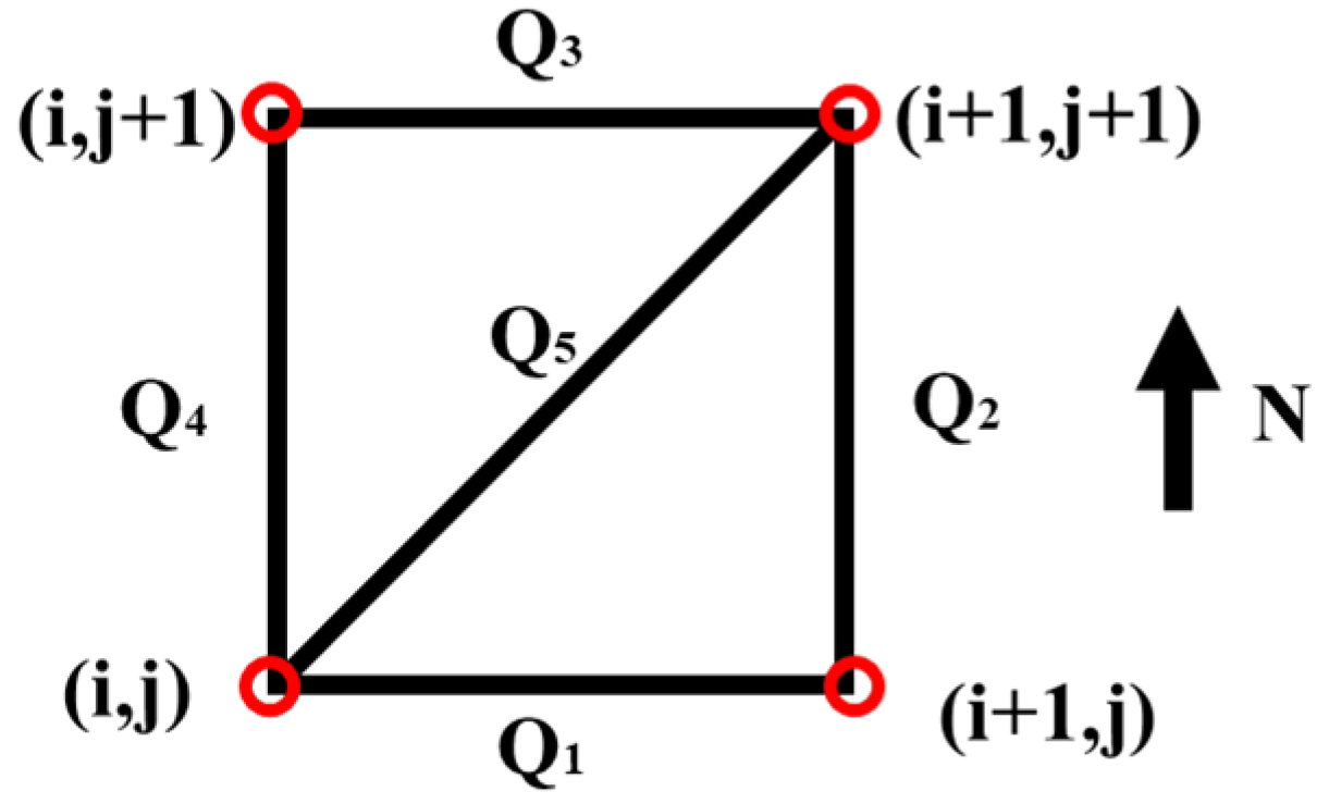
Figure 6 illustrates a grid where point (i, j) is considered as the origin, with adjacent points spaced by distance d. Q represents the radiation received by a transmission line element at a certain moment. While both direct and scattered components are considered, only the discussion on the direct component is presented here.
The slope is defined as the ratio of the height difference between two points to the horizontal distance.
s l o p e = Δ z Δ x 2 + Δ y 2
For the grid in Figure 6, the slope between adjacent points is represented as
s l o p e 1 = z ( i + 1 , j ) z ( i , j ) d s l o p e 2 = z ( i + 1 , j + 1 ) z ( i + 1 , j ) d s l o p e 3 = z ( i + 1 , j + 1 ) z ( i , j + 1 ) d s l o p e 4 = z ( i , j + 1 ) z ( i , j ) d
s l o p e 5 = 1 2 2 ( z ( i + 1 , j + 1 ) z ( i + 1 , j ) d + z ( i + 1 , j ) z ( i , j ) d + z ( i + 1 , j + 1 ) z ( i , j + 1 ) d + z ( i , j + 1 ) z ( i , j ) d )
According to (12), the different horizontal angles and orientations of the transmission lines only affect the magnitude of fAngle.
f 2 A n g l e = b + k sin 2 ( a n g l e )
b = ( sin 2 ( α ) + cos 2 ( α ) sin 2 ( γ a s p e c t ) ) k = ( cos 2 ( α ) sin 2 ( α ) + cos 2 ( α ) sin 2 ( γ a s p e c t ) )
f 2 A n g l e 5 = b 5 + k 5 sin 2 ( arctan ( p = 1 4 tan ( arccos ( 1 2 ( f 2 A n g l e p b p ) k p ) 2 ) 2 2 ) )
At time t = t0, in the absence of obstruction, the direct radiation flux received at each point in space is the same. Equation (13) can be expressed as
Q p = f a n g l e p f h i d e p q 0 , p = 1 , 2 , 3 , 4
q 0 = Q s u n c o n s t β m ( ζ ) Δ t
where q0 shows that the direct radiation flux received at each point in space is the same.
It is worth noting that when the obstruction coefficient was initially defined, it was intended for a point with height. For the definition of the obstruction coefficient applicable to a line, the following is defined, where N is the number of points along the line.
f h i d e l i n e = i = 1 N f h i d e i N
Assuming Qp is the solar radiation of four transmission lines in a grid, Equation (23) can be expressed as
f 2 A n g l e p = Q p 2 q 0 2 f h i d e p 2
Finally, Q5 in Figure 6 can be obtained from the following equation.
Q 5 = f h i d e 5 q 0 b 5 + k 5 sin 2 ( arctan ( p = 1 4 tan ( arccos ( 1 2 ( Q p 2 q 0 2 b p ) k p ) 2 ) 2 2 ) )

2.5. Joule Heating of the Current

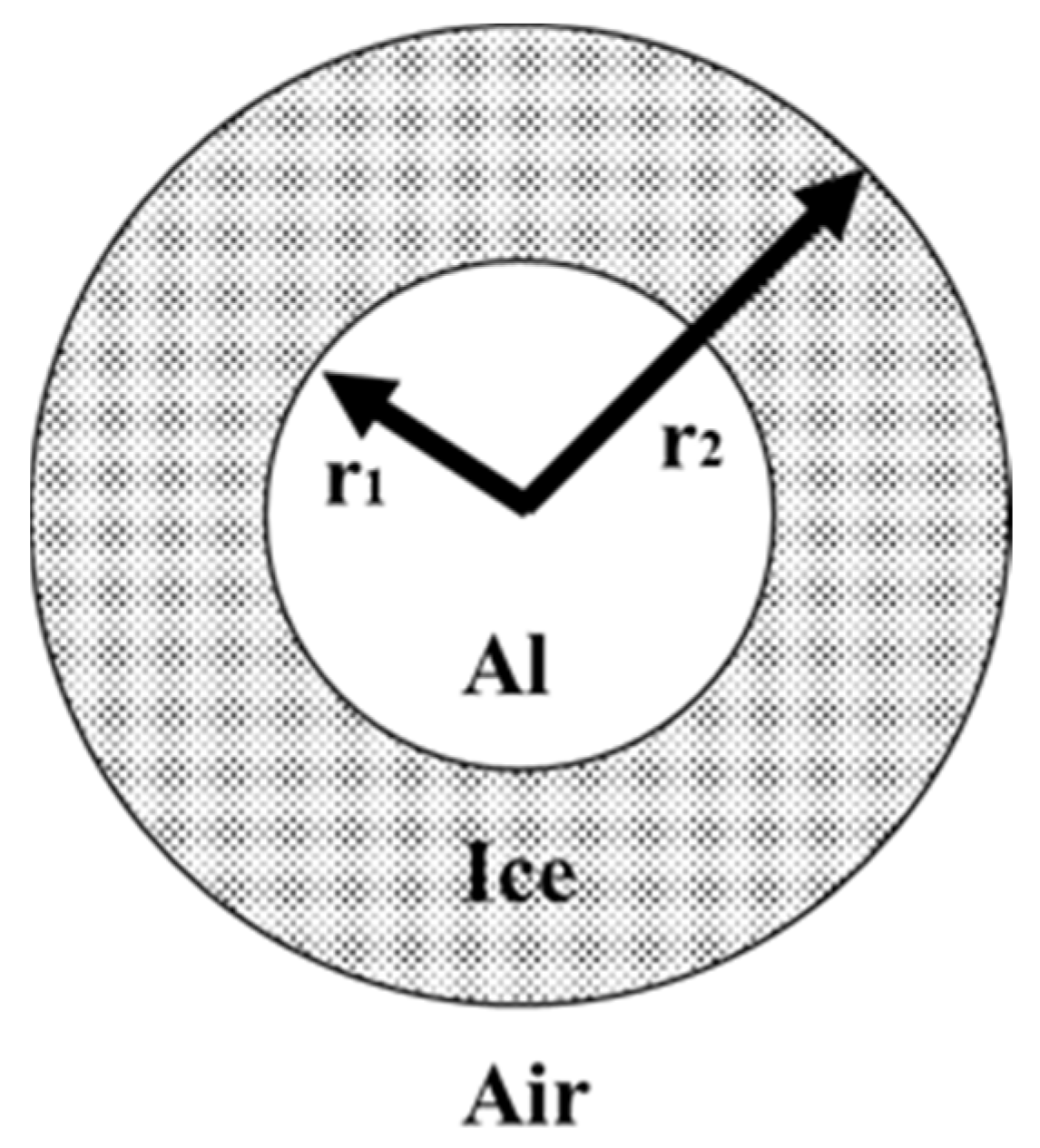
The Joule heating QI is the process of heat generation as a current passes through a conductor. As illustrated in Figure 7, considering an ice-covered conductor with aluminum core and uniform ice layer thickness.
For example, considering an LGJ-240/30 conductor with a radius rc = 21.6 mm and an outer ice layer thickness d = 10 mm, and a resistivity rt = 0.1181 Ω/km, I represents the effective value of the current, h is the forced convection coefficient, ts is the temperature on the outer surface of the ice layer, and λ1, λ2 are, respectively, the thermal conductivities of the conductor and ice. When the temperature on the inner surface of the ice layer is 0 °C, the critical ice-melting current is determined.
Q I = I 2 r t
I 2 r t = h ( t s t a )
0 t s I 2 r t = ln ( r i / r c ) 2 π λ 2 l
I = 2 t s λ 2 π r t ( λ 2 h r 2 + ln r i r c )

2.6. Heat of Ice Melting

The melting process of ice consists of two stages: firstly, absorbing heat until the temperature gradually rises to 0 °C, and then undergoing phase transition from ice to water. The required heat can be calculated using the following equation.
Q i c e = ( t a t s ) m i c e C i c e + m i c e C l a t e n t
where mice is the mass of ice, Cice is the specific heat capacity of ice, and Clatant is the latent heat of fusion of ice.

3. Results and Discussion

3.1. The Impact of Terrain Shading on Solar Radiation

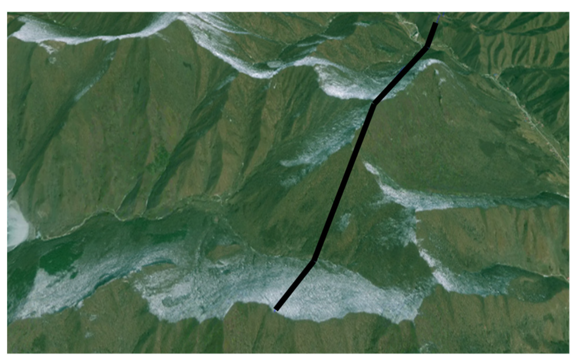
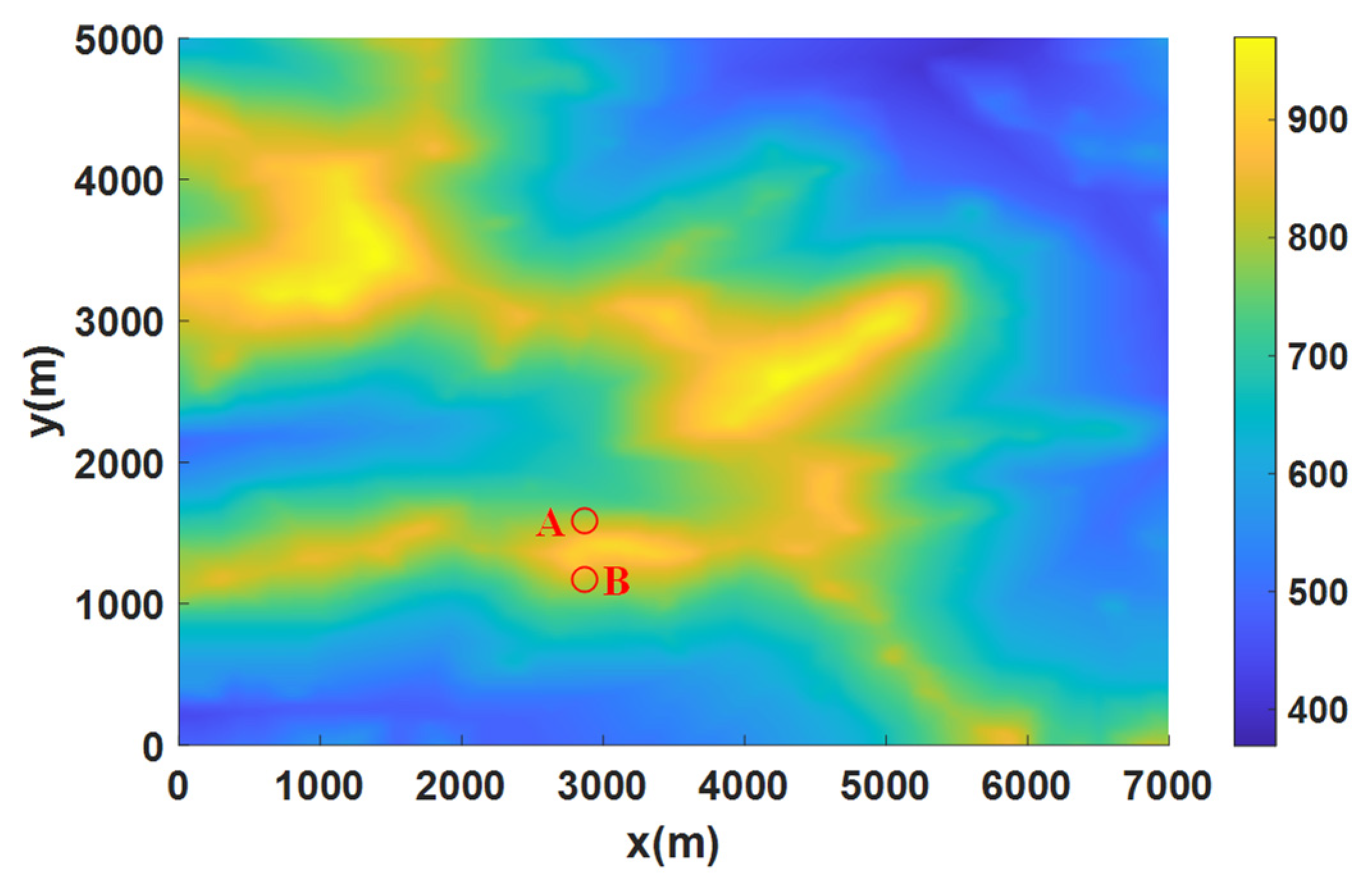
Figure 8 depicts a realistic and complex terrain through which a 220 kV transmission line passes, with the black lines representing the transmission line in the image. In conjunction with Figure 9, after winter snowfall, there is a stark contrast in the snow cover between the side of the mountain facing the sun and the side facing away from the sun. The surface facing away from the sun is more prone to snow accumulation. This phenomenon is attributed to the fact that in the Northern Hemisphere, the side of the mountain facing the sun is more likely to receive solar radiation from the south. The convention is to define the +Y direction as north and the orientation as 0°.
Transmission lines in areas facing away from the sun are more prone to terrain obstruction. Figure 10 illustrates a viewshed for two points at a height of 10 m above the ground. In Figure 11a, the red line represents the position of the sun throughout the day. It can be observed that the solar altitude angle is always smaller than the maximum horizontal angle over the course of a day, indicating that the direct solar radiation flux at point A is zero. Similarly, in Figure 11b, point B is positioned on the south side of the mountain at the same height above the ground. The viewshed shows that this point obstructs direct solar radiation from the north. In the northern hemisphere, sunlight is only received from the north, so this point does not actually obstruct direct solar radiation. Locations at a certain height above the ground cannot receive direct solar radiation, and the same applies to locations on the ground. However, as the height increases, the obstructive effect of the terrain should gradually decrease.
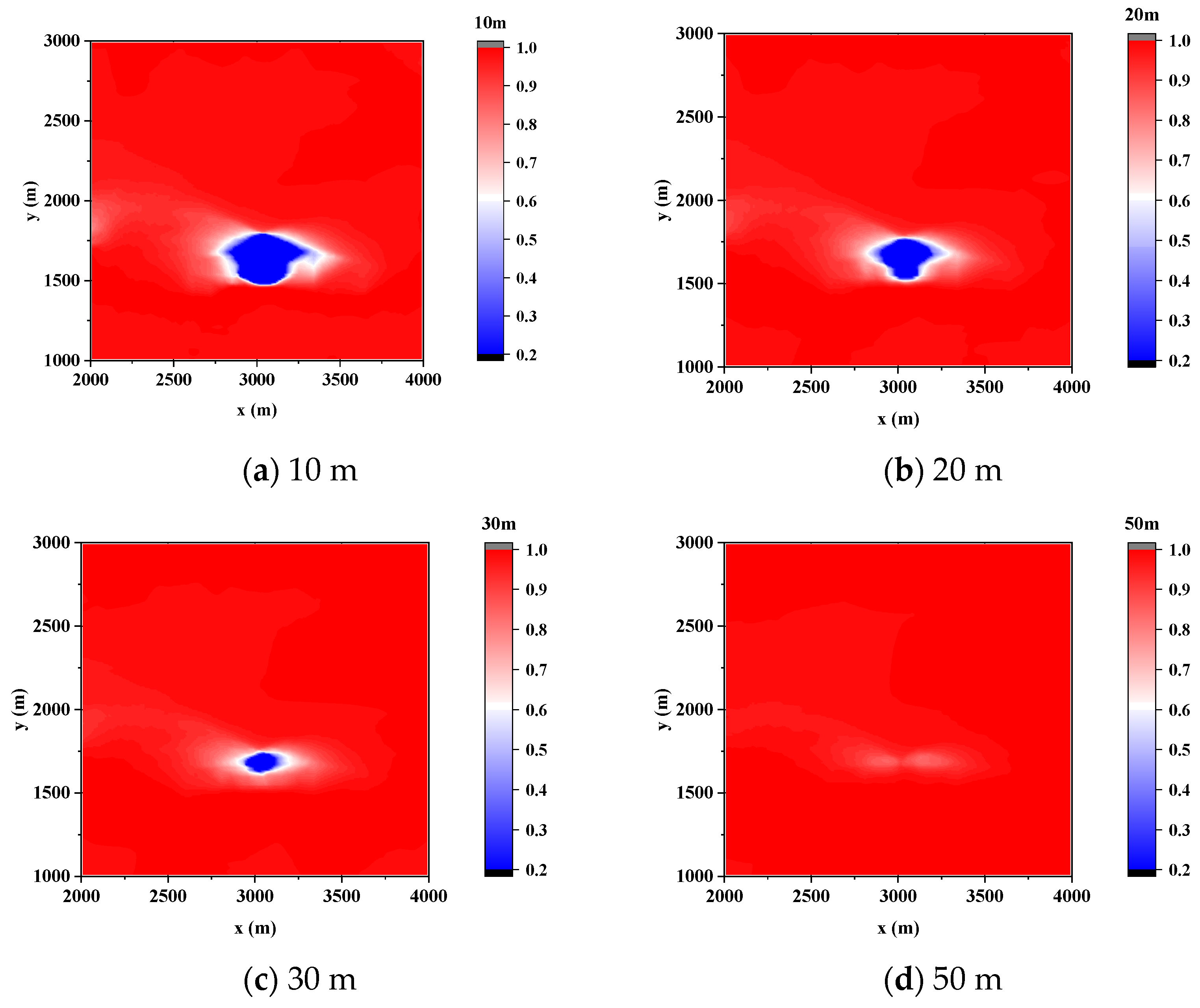
The shading effect is expressed using the normalization coefficient fshade, which varies with different heights above the ground. Figure 12 illustrates the shading effect at various heights above the ground. At a height of 10 m, some locations are unable to receive direct solar radiation throughout the day and can only receive scattered radiation. As direct sunlight constitutes the majority of solar radiation, the absence of this component can lead to a maximum reduction in daily radiation of up to 78%. As the height above the ground increases, the obstruction of terrain to direct solar radiation gradually diminishes. Once the height above the ground reaches 50 m, the shading effect of terrain on solar radiation becomes negligible.

3.2. Analysis of Factors Affecting Radiation Received by Transmission Lines

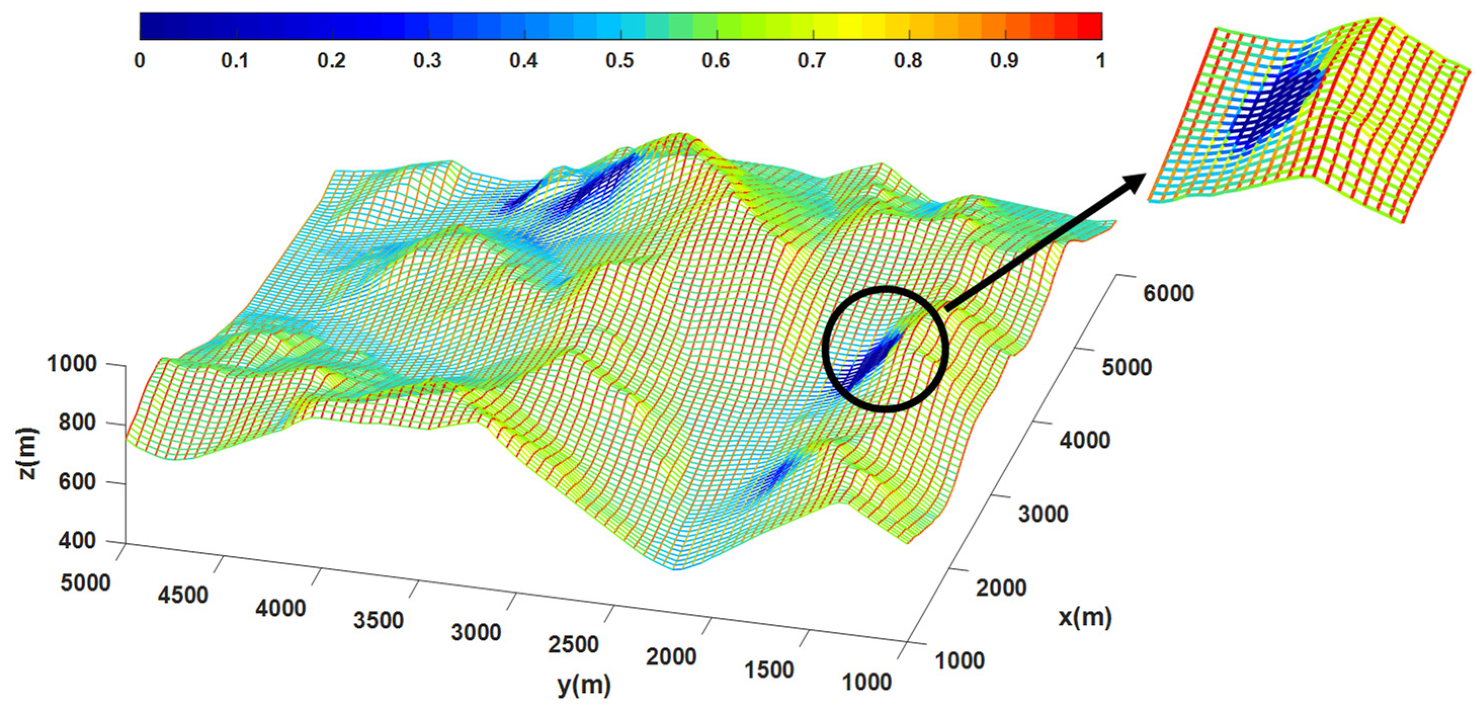
The actual terrain is divided into square grids of equal size, with adjacent nodes determining the slope and orientation of the transmission lines. The orientation increases clockwise, with a spacing set at L = 50 m. The daily radiation flux for each transmission line is normalized, as shown in Figure 13. Upon zooming into a specific area in the figure, it can be observed that the solar radiation for transmission lines with a 90° orientation is significantly higher than those with a 0° orientation. This is because, in the northern hemisphere, the sun rises from the southeast, passes through the south, and eventually sets in the southwest, making transmission lines with a 0° orientation more susceptible to receiving solar radiation.
At the same location, the solar radiation received by transmission lines varies with different orientations, and the data for other orientations cannot be obtained through the interpolation of grid data. Therefore, Figure 13 only displays data for 0° and 90° orientations, with each edge of the grid representing a transmission line. As for the data for other orientations, the method for calculating the solar radiation received by transmission lines at a 45° orientation is provided in Section 2.3, based on four data points within a grid.
The solar radiation flux values for three orientations are recorded in Table 1, with the minimum occurring when the terrain completely obstructs the direct component, leaving only scattered radiation. Starting from 0° orientation, the maximum values increased by 14.1% and 18.2%, respectively, while the minimum values increased by 12.3% and 13.7%, and the average increased by 25.4% and 17.4%.

3.3. Sensitivity Analysis

3.3.1. The Impact of Solar Position

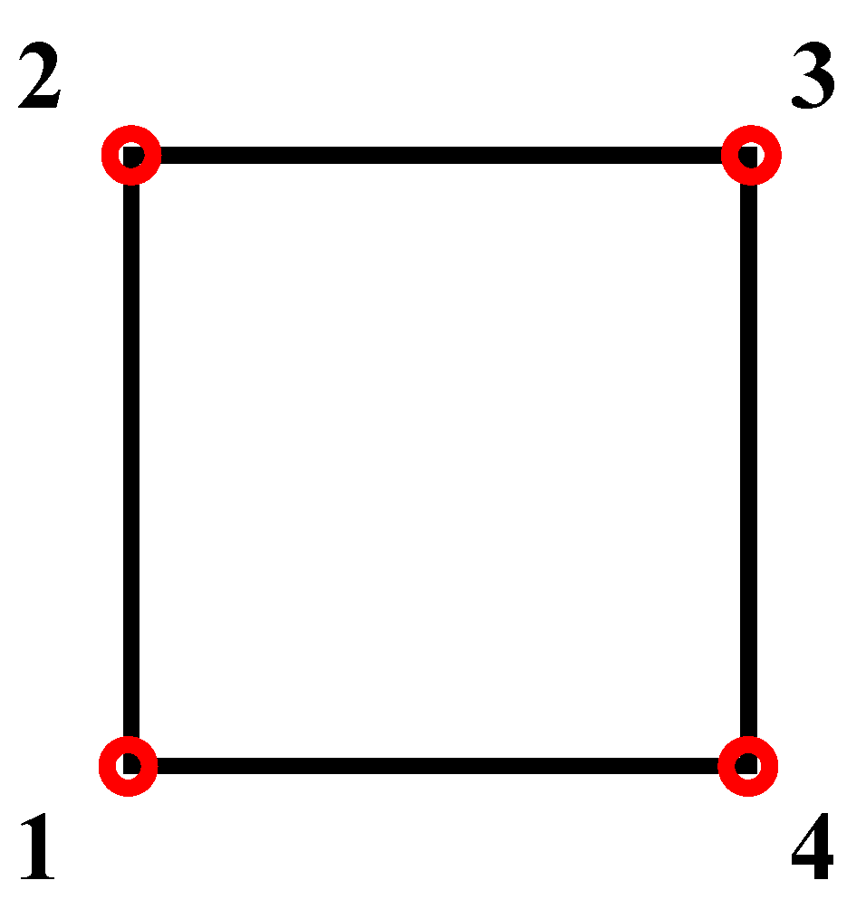
The solar position is assumed to be the same for every location within the region. This assumption is reasonable for a small spatial area. As shown in Figure 14, Four coordinates representing the edges of the study area were selected, with the central coordinates as the reference point. The maximum influence of latitude and longitude differences on the data is 0.26% in Table 2. The sensitivity to changes in latitude is higher than that to changes in longitude. Therefore, within the micro-terrain area shown in the figure, differences in solar position can be disregarded.

3.3.2. The Azimuthal Resolution

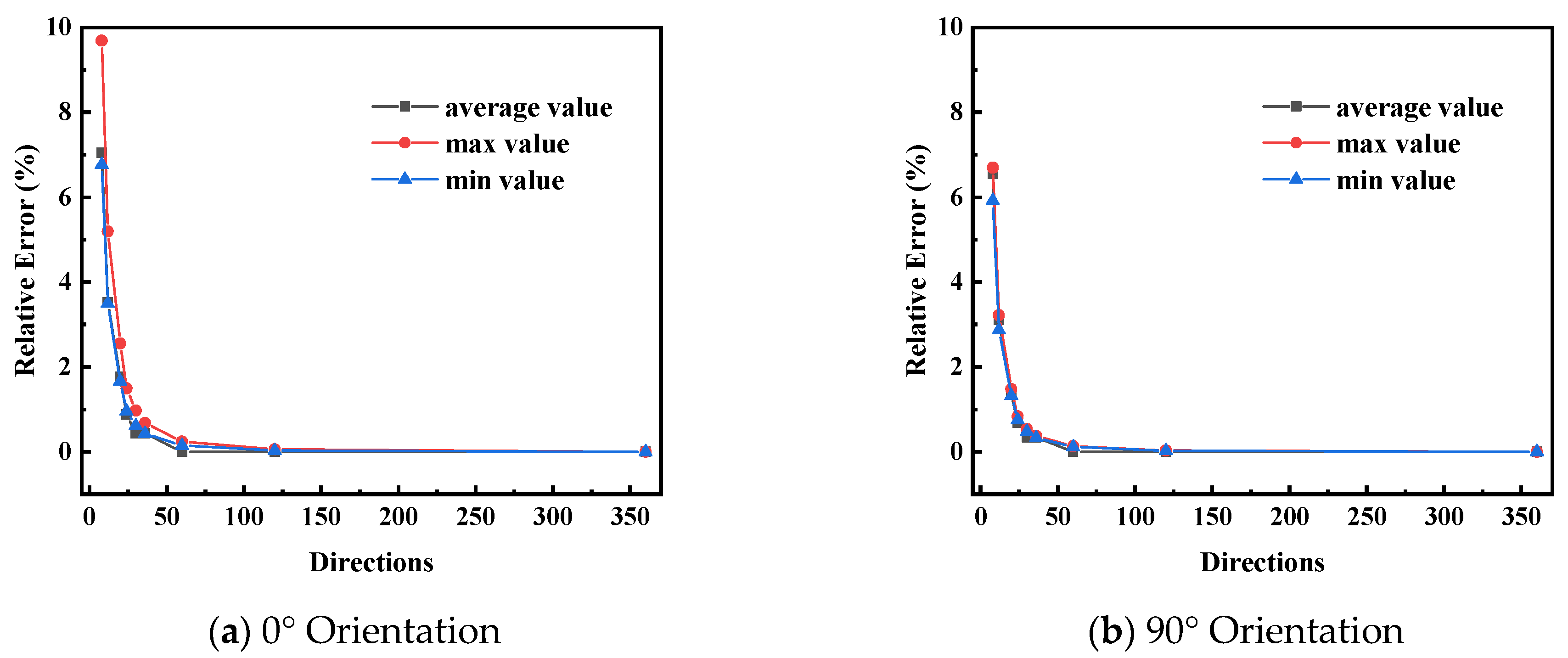
When calculating the scattered radiation, the entire sky is divided into multiple sky sectors based on azimuthal and elevation angle resolutions. With an azimuthal resolution of 45°, there are only eight directions, just like in Figure 4a, and the remaining directions are calculated through interpolation, which cannot fully reflect the impact of terrain shading. A higher number of directions will result in higher accuracy. Figure 15 shows the relative error of scattered radiation for different numbers of directions, with the data for 360 directions as the reference. After the number of directions reaches 60, the results will no longer fluctuate with an increase in the number of directions.

3.4. Equivalent Ice Melting

The transparency of ice on the surface of the transmission line is affected by the internal air content. Glazed ice has a hard and transparent texture and hoarfrost is white. The absorption rate of ice is taken as 0.2. When the environmental temperature is −5 °C and the wind speed is 5 m/s, the critical ic-melting current for the LGJ-240/30 conductor is 509 A, with a power of 30.6 W. When the ice temperature is equal to the environmental temperature, it requires 344 J of heat to convert 1 g of ice to water at 0 °C. In Table 3, solar radiation is converted into equivalent ice melting amount For each unit length of a transmission line, the maximum radiation received per day can reduce 528.7 g of ice. This is equivalent to a 509 A current working for 12.4 min.

4. Conclusions

The mechanism of ice formation on transmission lines in micro-terrain and microclimate conditions requires an accurate analysis of the relationship between the transmission lines and the local environment affected by surface terrain. Solar radiation is one of the external heat sources for transmission lines; however, there is a lack of assessment methods for calculating the radiant heat of transmission lines in related research. This work, based on the evaluation method of solar angles in existing ground radiation calculation methods, further proposes a method to calculate the effective radiation received by transmission lines in three-dimensional space. This allows for the determination of the total amount of radiant heat affected by surrounding terrain at different heights of the transmission lines under varying solar angles throughout the day. In response to the engineering needs of power grid route planning for a distribution map of line radiation levels, a method for drafting a grid-based thermal radiation map of transmission lines has been proposed. This involves setting a series of equidistant points, with the transmission line identified by a line connecting two adjacent points. The grid is considered to be composed of transmission lines oriented at 0° and 90°, and data for other orientations can be calculated using the four data points on the grid. This method offers the daily thermal radiation received by transmission lines varying with the orientation of the ground terrain and further provides their equivalent Joule heat based on the phase change heat absorption model of ice.
The outcomes of this project serve as a robust tool for power grid planning in areas with micro-topography and microclimates. As a method to assessing the influence of radiation on OHL, it can be applied to calculation of thermal sag in transmission lines and other aspects related to the thermal stability of high-voltage equipment.

Author Contributions

Conceptualization, H.Z. and Y.W.; methodology, H.Z. and Y.W.; software, Y.W.; validation, D.X., Z.Z. and X.J.; formal analysis, Y.W.; investigation, Y.W.; resources, Y.W.; data curation, Y.W.; writing—original draft preparation, H.Z.; writing—review and editing, Y.W.; visualization, Y.W.; supervision, D.X.; project administration, Z.Z.; funding acquisition, X.J. All authors have read and agreed to the published version of the manuscript.

Funding

This research was supported by Project No. 2022CDJJJ-016 supported by the Fundamental Research Funds for the Central Universities, and Project No. 2024CDJCGJ-004, supported by the Fundamental Research Funds for the Central Universities.

Data Availability Statement

The data presented in this study are available on request from the corresponding author.

Conflicts of Interest

Author Dexin Xie was employed by the company Chongqing Electric Power Design Institute Co., Ltd. The remaining authors declare that the research was conducted in the absence of any commercial or financial relationships that could be construed as a potential conflict of interest.

References

  1. Wang, L.; Chen, Z.; Zhang, W.; Lu, Z.; Cheng, Y.; Qu, X.; Gul, C.; Yang, Y. The Causes and Forecasting of Icing Events on Power Transmission Lines in Southern China: A Review and Perspective. Atmosphere 2023, 14, 1815. [Google Scholar] [CrossRef]
  2. Deng, Y.; Jiang, X.; Wang, H.; Yang, Y.; Virk, M.S.; Liao, Y.; Wu, J.; Zhao, M. Multimodal analysis of saddle micro-terrain prone to wind disasters on overhead transmission lines. Electr. Power Syst. Res. 2024, 229, 110143. [Google Scholar] [CrossRef]
  3. Lu, J.; Guo, J.; Hu, J.; Yang, L.; Feng, T. Analysis of ice disasters on ultra-high-voltage direct-current transmission lines. Nat. Hazards 2017, 86, 203–217. [Google Scholar] [CrossRef]
  4. Tan, L.; Liu, Y.; Yuan, Z.; Li, R. Linear modeling analysis of the heat balance of the transmission line in high frequency critical ice melting state. Int. J. Low-Carbon Technol. 2024, 19, 508–516. [Google Scholar] [CrossRef]
  5. Zhang, Z.; Zhang, H.; Yue, S.; Zeng, W. A Review of Icing and Anti-Icing Technology for Transmission Lines. Energies 2023, 16, 601. [Google Scholar] [CrossRef]
  6. Li, Y.; Ma, W.; Kwon, Y.S.; Li, W.; Yao, S.; Huang, B. Solar deicing nanocoatings adaptive to overhead power lines. Adv. Funct. Mater. 2022, 32, 2113297. [Google Scholar] [CrossRef]
  7. Frey, K.E.; Perovich, D.K.; Light, B. The spatial distribution of solar radiation under a melting Arctic sea ice cover. Geophys. Res. Lett. 2011, 38, L22501. [Google Scholar] [CrossRef]
  8. Light, B.; Grenfell, T.C.; Perovich, D.K. Transmission and absorption of solar radiation by Arctic sea ice during the melt season. J. Geophys. Res. Oceans 2008, 113, C03023. [Google Scholar] [CrossRef]
  9. Ruiz-Arias, J.A.; Tovar-Pescador, J.; Pozo-Vázquez, D.; Alsamamra, H. A comparative analysis of DEM-based models to estimate the solar radiation in mountainous terrain. Int. J. Geogr. Inf. Sci. 2009, 23, 1049–1076. [Google Scholar] [CrossRef]
  10. Akarslan, E.; Hocaoglu, F.O.; Edizkan, R. Novel short term solar irradiance forecasting models. Renew. Energy 2018, 123, 58–66. [Google Scholar] [CrossRef]
  11. Pang, Z.; Niu, F.; O’neill, Z. Solar radiation prediction using recurrent neural network and artificial neural network: A case study with comparisons. Renew. Energy 2020, 156, 279–289. [Google Scholar] [CrossRef]
  12. Bailek, N.; Bouchouicha, K.; Al-Mostafa, Z.; El-Shimy, M.; Aoun, N.; Slimani, A.; Al-Shehri, S. A new empirical model for forecasting the diffuse solar radiation over Sahara in the Algerian Big South. Renew. Energy 2018, 117, 530–537. [Google Scholar] [CrossRef]
  13. Feng, L.; Lin, A.; Wang, L.; Qin, W.; Gong, W. Evaluation of sunshine-based models for predicting diffuse solar radiation in China. Renew. Sustain. Energy Rev. 2018, 94, 168–182. [Google Scholar] [CrossRef]
  14. Kambezidis, H.D. The solar radiation climate of Athens: Variations and tendencies in the period 1992–2017, the brightening era. Sol. Energy 2018, 173, 328–347. [Google Scholar] [CrossRef]
  15. Dong, N.; Chang, J.-F.; Wu, A.-G.; Gao, Z.-K. A novel convolutional neural network framework based solar irradiance prediction method. Int. J. Electr. Power Energy Syst. 2020, 114, 105411. [Google Scholar] [CrossRef]
  16. Feng, Y.; Zhang, X.; Jia, Y.; Cui, N.; Hao, W.; Li, H.; Gong, D. High-resolution assessment of solar radiation and energy potential in China. Energy Convers. Manag. 2021, 240, 114265. [Google Scholar] [CrossRef]
  17. Wang, L.; Lu, Y.; Zou, L.; Feng, L.; Wei, J.; Qin, W.; Niu, Z. Prediction of diffuse solar radiation based on multiple variables in China. Renew. Sustain. Energy Rev. 2019, 103, 151–216. [Google Scholar] [CrossRef]
  18. Thornton, P.E.; Hasenauer, H.; White, M.A. Simultaneous estimation of daily solar radiation and humidity from observed temperature and precipitation: An application over complex terrain in Austria. Agric. For. Meteorol. 2000, 104, 255–271. [Google Scholar] [CrossRef]
  19. Bellaoui, M.; Bouchouicha, K.; Oulimar, I. Estimation of daily global solar radiation based on MODIS satellite measurements: The case study of Adrar region (Algeria). Measurement 2021, 183, 109802. [Google Scholar] [CrossRef]
  20. Wang, K.; Zhou, X.; Liu, J.; Sparrow, M. Estimating surface solar radiation over complex terrain using moderate-resolution satellite sensor data. Int. J. Remote. Sens. 2005, 26, 47–58. [Google Scholar] [CrossRef]
  21. Zhang, C.; Guo, Y.; He, Z.; He, L.; Xu, H. Analysis of influence mechanism of spatial distribution of incoming solar radiation based on DEM. Earth Sci. Inform. 2022, 15, 635–648. [Google Scholar] [CrossRef]
  22. Fibbi, L.; Maselli, F.; Pieri, M. Improved estimation of global solar radiation over rugged terrains by the disaggregation of Satellite Applications Facility on Land Surface Analysis data (LSA SAF). Meteorol. Appl. 2020, 27, e1940. [Google Scholar] [CrossRef]
  23. Yang, L.; Gao, X.; Li, Z.; Jia, D.; Jiang, J. Nowcasting of surface solar irradiance using FengYun-4 satellite observations over China. Remote Sens. 2019, 11, 1984. [Google Scholar] [CrossRef]
  24. Cornejo-Bueno, L.; Casanova-Mateo, C.; Sanz-Justo, J.; Salcedo-Sanz, S. Machine learning regressors for solar radiation estimation from satellite data. Sol. Energy 2019, 183, 768–775. [Google Scholar] [CrossRef]
  25. Bright, J.M. Solcast: Validation of a satellite-derived solar irradiance dataset. Sol. Energy 2019, 189, 435–449. [Google Scholar] [CrossRef]
  26. Doorga, J.R.S.; Dhurmea, K.R.; Rughooputh, S.; Boojhawon, R. Forecasting mesoscale distribution of surface solar irradiation using a proposed hybrid approach combining satellite remote sensing and time series models. Renew. Sustain. Energy Rev. 2019, 104, 69–85. [Google Scholar] [CrossRef]
  27. Ghimire, S.; Deo, R.C.; Downs, N.J.; Raj, N. Self-adaptive differential evolutionary extreme learning machines for long-term solar radiation prediction with remotely-sensed MODIS satellite and Reanalysis atmospheric products in solar-rich cities. Remote. Sens. Environ. 2018, 212, 176–198. [Google Scholar] [CrossRef]
  28. Zhang, S.; Li, X.; She, J.; Peng, X. Assimilating remote sensing data into GIS-based all sky solar radiation modeling for mountain terrain. Remote Sens. Environ. 2019, 231, 111239. [Google Scholar] [CrossRef]
  29. Wang, T.; Yan, G.; Mu, X.; Jiao, Z.; Chen, L.; Chu, Q. Toward operational shortwave radiation modeling and retrieval over rugged terrain. Remote Sens. Environ. 2018, 205, 419–433. [Google Scholar] [CrossRef]
  30. Liu, M.; Bárdossy, A.; Li, J.; Jiang, Y. GIS-based modelling of topography-induced solar radiation variability in complex terrain for data sparse region. Int. J. Geogr. Inf. Sci. 2012, 26, 1281–1308. [Google Scholar] [CrossRef]
  31. Dozier, J.; Frew, J. Rapid calculation of terrain parameters for radiation modeling from digital elevation data. IEEE Trans. Geosci. Remote Sens. 1990, 28, 963–969. [Google Scholar] [CrossRef]
  32. Dubayah, R.; Rich, P.M. Topographic solar radiation models for GIS. Int. J. Geogr. Inf. Syst. 1995, 9, 405–419. [Google Scholar] [CrossRef]
  33. Kodysh, J.B.; Omitaomu, O.A.; Bhaduri, B.L.; Neish, B.S. Methodology for estimating solar potential on multiple building rooftops for photovoltaic systems. Sustain. Cities Soc. 2013, 8, 31–41. [Google Scholar] [CrossRef]
  34. Li, Y.; Ding, D.; Liu, C.; Wang, C. A pixel-based approach to estimation of solar energy potential on building roofs. Energy Build. 2016, 129, 563–573. [Google Scholar] [CrossRef]
  35. Hong, T.; Lee, M.; Koo, C.; Jeong, K.; Kim, J. Development of a method for estimating the rooftop solar photovoltaic (PV) potential by analyzing the available rooftop area using Hillshade analysis. Appl. Energy 2017, 194, 320–332. [Google Scholar] [CrossRef]
  36. Tscholl, S.; Tasser, E.; Tappeiner, U.; Vigl, L.E. Coupling solar radiation and cloud cover data for enhanced temperature predictions over topographically complex mountain terrain. Int. J. Clim. 2022, 42, 4684–4699. [Google Scholar] [CrossRef]
  37. Chen, N. Deriving the slope-mean shielded astronomical solar radiation spectrum and slope-mean possible sunshine duration spectrum over the Loess Plateau. J. Mt. Sci. 2020, 17, 133–146. [Google Scholar] [CrossRef]
  38. Baek, J.; Choi, Y.J.E. Comparative study on shading database construction for urban roads using 3d models and fisheye images for efficient operation of solar-powered electric vehicles. Energies 2022, 15, 8228. [Google Scholar] [CrossRef]
  39. Xu, L.; Long, E.; Wei, J.; Cheng, Z.; Zheng, H. A new approach to determine the optimum tilt angle and orientation of solar collectors in mountainous areas with high altitude. Energy 2021, 237, 121507. [Google Scholar] [CrossRef]
  40. Gardashov, R.; Eminov, M.; Kara, G.; Kara, E.G.E.; Mammadov, T.; Huseynova, X. The optimum daily direction of solar panels in the highlands, derived by an analytical method. Renew. Sustain. Energy Rev. 2020, 120, 109668. [Google Scholar] [CrossRef]
  41. Fu, P. A Geometric Solar Radiation Model with Applications in Landscape Ecology. Ph.D. Thesis, University of Kansas, Lawrence, KS, USA, 2000. [Google Scholar]
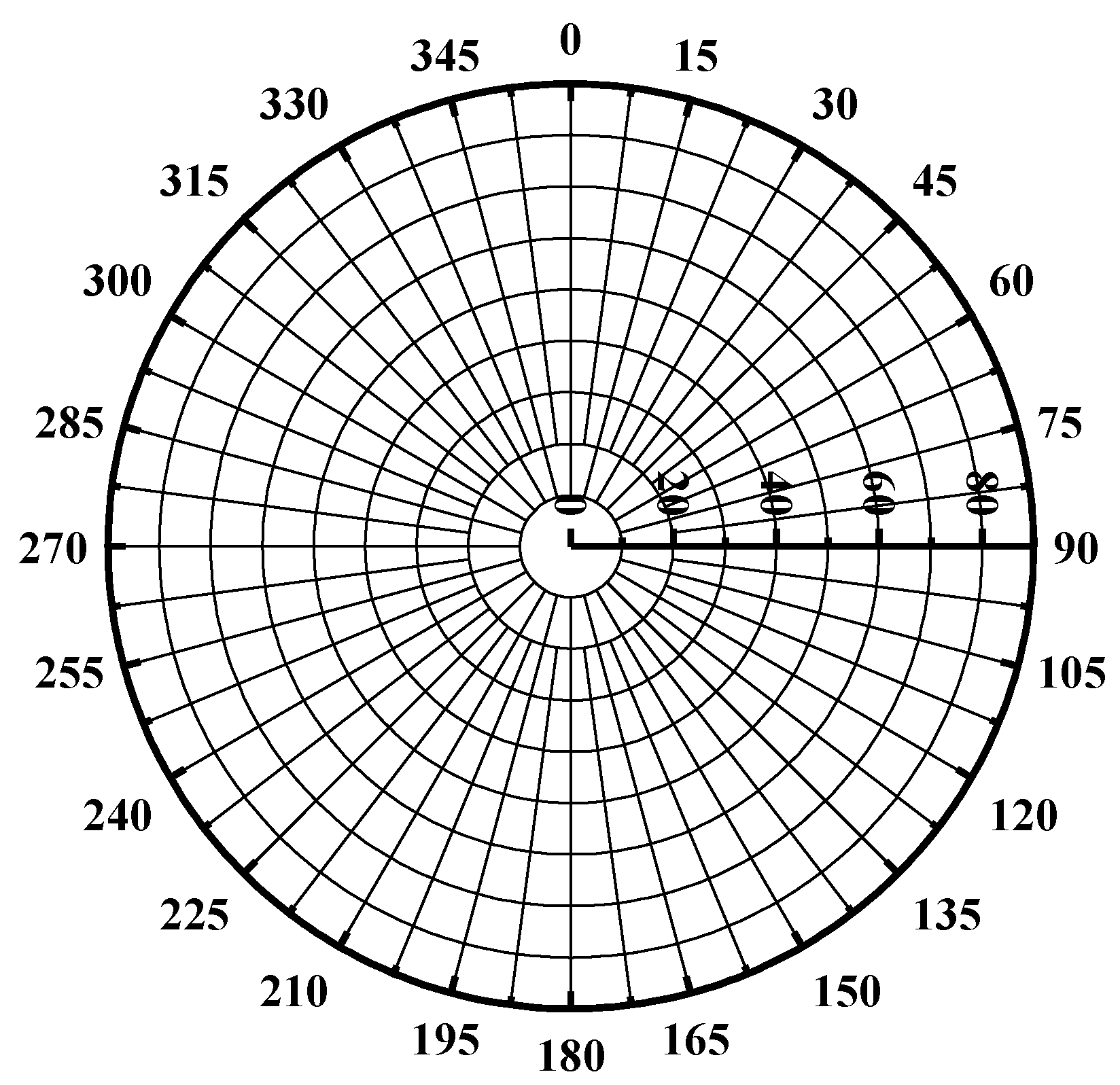
Figure 2. Solar sectors.
Energies 17 01684 g002
Figure 3. Terrain shading.
Energies 17 01684 g003
Figure 4. Calculation of horizontal angle.
Energies 17 01684 g004
Figure 5. Transmission line oriented at 45°.
Energies 17 01684 g005
Figure 6. Schematic illustration of the calculation for a transmission line oriented at 45°.
Energies 17 01684 g006
Figure 7. Ice-covered conductor.
Energies 17 01684 g007
Figure 8. The satellite image displays the icing situation in mountainous areas after an icing event, with the white areas indicating the unthawed icing, while the solid black lines indicate a 220 kV transmission line.
Energies 17 01684 g008
Figure 9. Accumulated surface radiation on 15 January.
Energies 17 01684 g009
Figure 10. Locations of two observation points showing in DEM.
Energies 17 01684 g010
Figure 11. Overlay o f a viewshed with a skymap.
Energies 17 01684 g011
Figure 12. Shading effects at different heights.
Energies 17 01684 g012
Figure 13. Solar radiation flux of transmission line grid at a height of 10 m above ground. (In the diagram, the positive Y-direction aligns with the north direction, and the positive X-direction aligns with the east direction. Clockwise direction is considered positive.)
Energies 17 01684 g013
Figure 14. The selected point locations.
Energies 17 01684 g014
Figure 15. Error caused by different directions.
Energies 17 01684 g015
Table 1. Solar radiation flux values for different orientations throughout the day.
OrientationMax Value (Wh/m2)Min Value (Wh/m2)Average Value (Wh/m2)
14492271181
45°16542551481
90°19552901792
Table 2. The error caused by different latitudes and longitudes.
Orientation 1234
Max value0.26%0.20%0.20%0.26%
Min value0.25%0.19%0.19%0.25%
90°Max value0.23%0.18%0.18%0.23%
Min value0.25%0.20%0.20%0.25%
Table 3. Ice-melting capacity of transmission lines with different orientations.
OrientationMaximum Daily Ice Melting (g)The Minimum Daily Ice Melting (g)
402.166.5
45°452.469.8
90°528.774.1
Disclaimer/Publisher’s Note: The statements, opinions and data contained in all publications are solely those of the individual author(s) and contributor(s) and not of MDPI and/or the editor(s). MDPI and/or the editor(s) disclaim responsibility for any injury to people or property resulting from any ideas, methods, instructions or products referred to in the content.