Article

Preventive-Security-Constrained Optimal Power Flow Model Considering IPFC Control Modes

1
Economic Research Institute, State Grid Jiangsu Electric Power Co., Ltd., Nanjing 210008, China
2
School of Electrical Engineering, Southeast University, Nanjing 210096, China
*
Author to whom correspondence should be addressed.
Energies 2024, 17(7), 1660; https://doi.org/10.3390/en17071660
Submission received: 22 February 2024 / Revised: 25 March 2024 / Accepted: 28 March 2024 / Published: 30 March 2024
(This article belongs to the Special Issue Future Acceptance of Renewable Energy System Economics and Policies)

Abstract

:
The interline power flow controller (IPFC) is one of the most versatile integrated flexible alternating current transmission systems (FACTS) controllers and can realize power flow control for multiple transmission lines in modern power systems. However, control characteristics are ignored in conventional IPFC models, in which unreasonable assumptions about injected voltages may lead to security problems in realistic operation. Besides, preventive security constraints considering IPFC control modes are not included in optimal power flow (OPF) control of the system with IPFC, squandering IPFC control potential. To solve these problems, a preventive-security-constrained optimal power flow (PSCOPF) model considering IPFC control modes is proposed in this paper. IPFC control characteristics under different control modes are analyzed and employed as constraints of the optimization model. The iterative updates of converter output voltages for different control modes are derived respectively for power flow calculation, and the power and voltages required in the objective function and constraints of the proposed model can then be obtained. Through optimal selection of IPFC control modes and control parameters, the proposed model can better reconcile the economical and secure operation of the system. Numerical results demonstrate the efficient performance and superiority of the PSCOPF model considering IPFC control modes.

1. Introduction

With the expansion of power grids and the integration of renewable energy, the problem of transmission overload is becoming increasingly serious [1]. The challenge deteriorates the economic operation of power systems and may even lead to severe threats to the safety of the system [2]. FACTS technologies provide rapid voltage or power flow regulation to overcome the challenge, thus effectively improving the operation of the system [3]. IPFC is one of the most potent and versatile integrated FACTS controllers [4]. With excellent potential and broad application prospects, IPFC provides full control for transmitted active power and reactive power flow simultaneously for multiple transmission lines [5]. IPFC has the capability to adjust main transmission parameters including voltage amplitude and angle, line impedance, and power flow based on corresponding control modes [6]. It is characterized as one of the best-featured FACTS devices, with an appropriate strategy, IPFC can improve static security of the power systems and mitigate power transmission bottlenecks [7,8].
For the system with IPFC, optimal power flow (OPF) is generally used to improve the economy and security of the power system in steady state [9]. OPF has been attracting researchers due to its contributions to the steady operation of the system, which is extremely important for a system with large regulation demand due to the integration of renewable energy [10]. The optimization of security-constrained economic dispatch is studied in [11], which sets economic indicators as the objective function and safety indicators as constraints [12]. OPF in [13] is used to realize congestion management and improve the economic operation of the system. OPF in [14] sets multi-objectives, including generation cost, active power loss, and voltage stability, for the economic and secure operation of the system. The obtained optimal operating point struck a balance between minimization of operating cost, voltage profile deviation, and feeder congestion [15].
IPFC models are required to be constructed at first for the OPF of the system. Variable-impedance-based models were proposed in [16], and impedance was introduced as decision variables to realize an economic optimum. However, the physical characteristics and operation constraints are hard to describe in terms of impedance, and low-impedance branches could cause ill conditioning of the admittance matrix. Voltage source models and power injection models are more suitable for the OPF problem [17]. In voltage source models, converters of IPFC devices are equalized by controllable voltage sources, but the introduction of additional buses in voltage source models leads to an asymmetric admittance matrix [18]. In power injection models, injected power and symmetric admittance matrices can be obtained and used for Newton–Raphson power flow calculation [19], for which Jacobian codes can be reused to reduce redundant matrix correction and programming complexity [20].
However, there are still limitations in the current research on OPF with IPFC [21]. Continuity and reliability of the power supply are important in existing power systems, and the current research about OPF focuses on the steady state of the power system [22,23]. IPFC control modes will affect power flow distribution after contingencies, but conventional IPFC and other FACTS models ignore control characteristics and regard injected voltages as unchanged before and after contingencies [24]. The unreasonable assumptions about injected voltages may lead to security problems in realistic operation. Additionally, remote contingencies are difficult to detect, so IPFC is hard to adjust accurately and rapidly after contingencies, which requires early selection of the IPFC control mode to realize preventive control [25].
To solve the OPF model with an IPFC, a nonlinear interior point algorithm incorporating a generalized IPFC is implemented in [26] to solve the OPF model and minimize operating costs. A sequential linear programming algorithm for the nonconvex OPF problem is proposed in [27], which captures transmission losses and reactive power, realizing more accurate locational marginal prices using LP solvers. Multi-objective OPF problems with IPFC were solved by an adaptive clonal selection algorithm and sequential quadratic programming respectively in [14,28]. However, the iterative update schemes for different IPFC control modes are not devised and no practical method can be used to calculate the required power and voltage in the optimization, making it difficult to solve the OPF model when IPFC control modes are considered [29].
To overcome the drawbacks above, a PSCOPF model considering IPFC control modes and a corresponding solution method are proposed. Note that we concentrate on 15 min level optimization in the paper without consideration of dynamic characteristics, which will be studied in the future research. The main contributions of this paper include:
(1)
A PSCOPF model considering IPFC control modes is established to fully utilize IPFC control potential, improving the economy and security of the system. IPFC control modes affect power flow distribution after contingencies and control characteristics under different control modes are analyzed, which are then employed as constraints of the optimization model. Economy and security margin are taken as the multi-objective function in the optimization, and the preventive-security-constrained technique is involved in realizing the optimal selection of IPFC control modes and control parameters in advance.
(2)
The corresponding method to solve the proposed model is deduced. Iterative schemes of converter output voltages and equivalent injected power for different IPFC control modes are derived respectively, and the power and voltages required in the proposed model can then be obtained. The calculated power and voltages in the objective function and constraints are further used to obtain the optimal result of the proposed model.
(3)
Advantages of the proposed model are proved in the case study through comparison with the original system, with the conventional model, and with optimization not considering IPFC control modes. Numerical results show that the optimal solution of the proposed model can decrease operation costs, improve voltage stability, and eliminate the risk of overload.
The remainder of this paper is as follows. The PSCOPF model considering IPFC control modes is constructed in Section 2. The solution method for the proposed model is provided in Section 3. The case study and conclusion are given in Section 4 and Section 5, respectively.

2. PSCOPF Model Considering IPFC Control Modes

2.1. Objective Function

To realize the optimal operation of the system in economy and security, the multi-objective function of the PSCOPF model can then be expressed as:
min F = E C + λ S e ,
where F is the overall objective function, EC is the economy function, Se is the security function, and λ is the weight coefficient to keep the economy and security indexes at the same level and measure the respective ratio.
(1)
Economy Function
In addition to IPFC regulation, some generators can also participate in optimal power flow control. The economy objective function intends to minimize the operating cost of the system under the same load distribution and can be calculated as:
E C = i = 1 N g ( c 2 i P g i 2 + c 1 i P g i + c 0 i ) ,
where Ng is the number of generators involved in optimal regulation; Pgi is the active power output of generator i; and c2i, c1i, and c0i are the cost coefficients of generator i.
(2)
Security Function
As renewable energy integration increases, the intermittent and stochastic characteristics of the output power have a significant impact on system operation, especially voltage stability [30]. The L-index, proposed by Kessel and Glavitsch in 1986, is used to predict voltage stability margins and is included in the security objective function [31]. For the PQ node βL and the PV node βG in the system, the corresponding relationship between voltages and currents can be expressed as:
V L I G = Z L L F L G K G L Y G G I L V G ,
where VL, IL, VG, and IG are voltage and current vectors of the PQ and PV nodes, respectively, and ZLL, FLG, KGL, and YGG are corresponding matrices and can be calculated from the admittance matrix as:
Z L L = ( Y L L ) 1 F L G = Y L G ( Y L L ) 1 K G L = Y G L ( Y L L ) 1 Y G G = ( Y L L Y G G Y L G Y G L ) ( Y L L ) 1 .
For any PQ node j, the voltage stability index Lj can be calculated as:
L j = 1 i β G F j i V i θ i V j θ j ,   j β L ,
where Fji is the (j,i) element in matrix FLG and is the load participation factor, Viθi is the ith PV node voltage in polar coordinates while iβG, and Vjθj is the jth PQ node voltage in polar coordinates while jβL.
Lj will reach 1.0 when the voltage of bus j reaches its collapse point [32]. Therefore, if Lj of a PQ node reaches 1.0, the system is at the critical point of voltage stability. If Lj of a PQ node is larger than 1.0, voltage instability has occurred. If Lj is less than 1.0 for all PQ nodes, the system is voltage-stable.
Vsi is the voltage stability index of the system under normal operation and can be expressed as:
V s i = max j β L L j .
To maintain stability before and after contingencies, the preventive-security-constrained technique is integrated to optimize the security of the system under various circumstances. After N − 1 contingency, the N − 1 line disconnects and admittance matrix Y and corresponding matrices in (4) change accordingly. Voltage stability index Li(c) and index of the system Vsi(c) after N − 1 contingency can be obtained as:
L j ( c ) = 1 i β G F j i ( c ) V i ( c ) θ i ( c ) V j ( c ) θ j ( c ) ,   j β L ,
V s i ( c ) = max j β L L j ( c ) ,
where (·)(c) represents the variables under contingency set NC.
As a part of the security objective function, the voltage stability index of the system Vs is then given by:
V s = V s i + c N c V s i ( c ) / N c .
The other part of the security objective function adds the number of overloaded lines Nlo as a penalty function to avoid transmission overload under normal operation and after contingencies, which is expressed as:
N l o = N l o i + c N c N l o i ( c ) / N c ,
where Nloi is the number of overloaded lines under normal operation and Nloi(c) is the number of overloaded lines after contingencies.
Combined with (9) and (10), the security objective function Se is calculated as:
S e = V s + σ N l o ,
where σ is the penalty parameter, indicating punishment intensity with a large value.

2.2. Constraints

The integration of IPFC will introduce new constraints to the system. To construct the constraints of the system and IPFC, an equivalent IPFC model is required first. IPFC compensates for multiple transmission lines simultaneously by insertion of series voltage source converters (VSC). The series converters can be equivalent to additional injected power to nodes based on the power injection method, and the IPFC equivalent power injection model with two series branches is shown in Figure 1.
Converters selected by the operator are then given priority to achieve control objectives, which are referred to as the “Master” converters. The other converter is referred to as the “Slave” and controls DC voltage to keep the stability of the converters. In Figure 1, the “Master” line of the system is transmission line ij, and the “Slave” line is transmission line ik. Nodes m and n are added as additional nodes for subsequent model derivation and power flow calculation. Pinj_i, Qinj_i, Pinj_m, Qinj_m, Pinj_n, and Qinj_n are equivalent injected power generated by converters at buses i, m, and n, respectively. Xseim and Xsein are equivalent impedances of the series output voltages. Viθi, Vjθj, and Vkθk are voltages of buses i, j, and k, respectively. Rij, Rik, Xij, Xik, Bcij, and Bcik are resistance, reactance, and admittance against the ground of transmission lines ij and ik, respectively.
(1)
Equality Constraints
Combined with IPFC equivalent injected power, the constraints of power balance can be modified as:
P g i P d i P i n j _ i = V i j = 1 N b V j ( G i j cos θ i j + B i j sin θ i j ) Q g i Q d i Q i n j _ i = V i j = 1 N b V j ( G i j sin θ i j B i j cos θ i j ) ,
where Nb is the total number of buses, including additional buses m and n. Nodes i and j are any nodes of the system, and i, jNb. Pgi and Qgi are the active and reactive power, respectively, of the generator at bus i. Pdi and Qdi are the active and reactive loads, respectively, at bus i. Pinj_i and Qinj_i are the active and reactive injected powers, respectively, at bus i. Pinj_i and Qinj_i are corresponding values related to IPFC injected power, and Pinj_i = 0, Qinj_i = 0 when buses i and j are not directly connected with IPFC. Gij and Bij are the conductance and susceptance, respectively, of transmission line ij. θij is the phase angle difference between nodes i and j.
Power balance after N − 1 contingency should also be satisfied as:
P g i ( c ) P d i ( c ) P i n j _ i ( c ) = V i ( c ) j = 1 N b V j i ( c ) ( G i j cos θ i j ( c ) + B i j sin θ i j ( c ) ) Q g i ( c ) Q d i ( c ) Q i n j _ i ( c ) = V i ( c ) j = 1 N b V j i ( c ) ( G i j sin θ i j ( c ) B i j cos θ i j ( c ) ) .
IPFC converters are connected to series transformers respectively on the AC side, and all converters are linked together at their DC terminals. Active power can be exchanged through the common DC link of VSCs. Therefore, accurate and flexible power flow control of multiple transmission lines can be realized at the same time. To maintain stability of the common DC bus voltage, the balance of active power exchange between converters of IPFC must be guaranteed and the sum of active power flowing through the DC link of converters must be zero. Ignoring the active power loss of IPFC, the active power conservation between converters can be deduced as:
V m sin ( θ s e i m θ m ) + V i sin ( θ i θ s e i m ) V s e i m / X s e i m + V n sin ( θ s e i n θ n ) + V i sin ( θ i θ s e i n ) V s e i n / X s e i n = 0 .
For the master converter of IPFC, there are four control modes, including impedance compensation control mode (ICCM), phase regulation control mode (PRCM), voltage regulation control mode (VRCM), and constant power control mode (CPCM) [6]. ICCM can match the existing capacitive line compensation in the system and controls the equivalent impedance, PRCM can be used for phase shifting and controls the voltage phase angle difference between connected buses, VRCM changes and controls the magnitude of the bus voltage, and CPCM schedules power flow directly and controls active and reactive power of the transmission line. The control mode variable X∈{1, 2, 3, 4} is incorporated into the optimization model for the optimal control mode, and corresponding settings are obtained as the optimization results as well.
X = 1 represents that the master converter works in ICCM. The equivalent impedances Zim and Zim(c) are intended to be equal to the set control target Zref as follows:
Z im = Z im ( c ) = Z r e f ,   X = 1 .
X = 2 represents that the master converter works in PRCM. The voltage phase angle differences θmi and θmi(c) between bus m and bus i, respectively, are intended to be equal to the set control target θref, and the voltage amplitude at bus m is intended to stay the same as that of bus i. These are given by:
θ m i = θ m i ( c ) = θ r e f V m = V i V m ( c ) = V i ( c ) ,   X = 2 .
X = 3 represents that the master converter works in VRCM. The voltage amplitudes Vm and Vm(c) at bus m are intended to be equal to the set control target Vref, and the voltage phase angle at bus m is intended to stay the same as at bus i and can be obtained as:
V m = V m ( c ) = V r e f θ m = θ i θ m ( c ) = θ i ( c ) ,   X = 3 .
X = 4 represents that the master converter works in CPCM. The active power and reactive power Pmj, Qmj, Pmj(c), and Qmj(c) of the transmission line mj are intended to be equal to the set control targets Pmjref, Qmjref, respectively, as follows:
P m j = P m j ( c ) = P m j r e f Q m j = Q m j ( c ) = Q m j r e f ,   X = 4 .
The slave converter needs to control the DC bus voltage, and only one control dimension remains. There are merely two modes: constant active power mode and quadrature compensating voltage control mode, and the former mode is generally selected for the emphasis of active power in actual system operation [6]. The active powers Pnk and Pnk(c) of the transmission line nk are intended to be equal to the set control target Pnkref and are given by:
P n k = P n k ( c ) = P n k r e f .
It is intended that thermal stability be realized after PSCOPF optimization, so in addition to converters, the generator output plan is intended to remain unchanged before and after N − 1 contingency. The constraint should be satisfied as:
V g i = V g i ( c ) P g i = P g i ( c ) ,
where Vgi is the voltage amplitude of the generator at PV bus i.
(2)
Inequality Constraints
In the power system, voltage amplitudes of the buses and output active power of the generators are required to satisfy the upper and lower bounds:
V i min V i V i max ,   V i min V i ( c ) V i max P i min P g i P i max ,   P i min P g i ( c ) P i max ,
where Vimin and Vimax are the minimum and maximum magnitudes, respectively, of voltage amplitude at any bus and Pgimin and Pgimax are the minimum and maximum magnitudes, respectively, of generator output active power.
Additionally, IPFC converters are required to meet the corresponding inequality constraints as follows:
0 | Re   ( V s e I i σ ) | P d c max ,   0 | Re   ( V s e ( c ) I i σ ( c ) ) | P d c max 0 V s e V s e max ,   0 V s e ( c ) V s e max 0 θ s e 2 π ,   0 θ s e ( c ) 2 π 0 I i σ I i σ max ,   0 I i σ ( c ) I i σ max ,
where Vse, Vse, and θse are the converter output AC voltage, voltage amplitude, and phase angle, respectively; I and I are the current and current amplitude through the converter, respectively; and Pdcmax, Vsemax, and Imax are the maximum interactive active power, output AC voltage amplitude, and output AC current of the converter, respectively.
Control modes of IPFC converters correspond to the control mode variable X and are analyzed in the proposed optimization model. In the optimization, the optimized objective function and control setting under each control mode are calculated, and the final optimized result of the proposed model is the optimum of all control modes in which the optimal control mode and setting values are included.

3. Solution Method for the PSCOPF Model Considering IPFC Control Modes

3.1. Framework of the Solution Method

The PSCOPF model above is a complex nonlinear optimization model that is hard to solve by the traditional method. The PSO algorithm is easy to implement and is applied to solve the model. Objective functions are set as the fitness function in the PSO algorithm. The optimization variables include IPFC control modes, IPFC control targets, voltage amplitudes of PV buses, and generator output active power. The equality constraints are satisfied in power flow calculation, and the inequality constraints are treated by introducing the penalty function.
Iterative schemes of converter output voltages and equivalent injected power for different IPFC control modes are derived respectively and used in the power flow calculation. The power and voltages required in the proposed model can then be obtained by power flow calculation. The calculated power and voltages in the objective function and constraints are further used to obtain the optimal result of the proposed optimization model. Figure 2 shows the process of solving the proposed model.
During the solving process, power flow iterative calculation is greatly related to IPFC control modes and is illustrated in detail in the next section.

3.2. Power Flow Calculation in the PSCOPF Model Solution Process

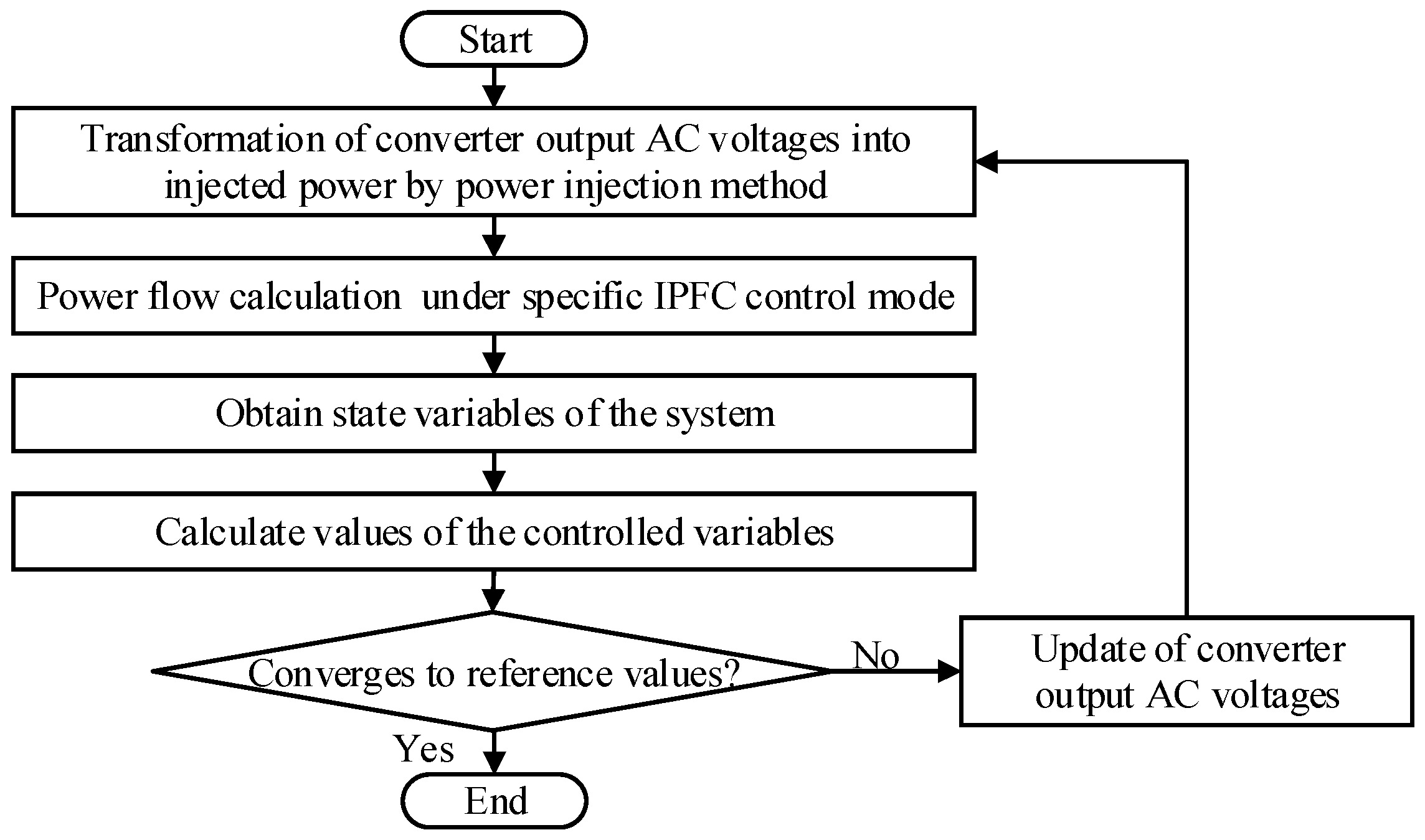
The power flow calculation method considering IPFC control modes can generally be divided into two parts. The first part transforms converter output AC voltages into injected power via the power injection method and updates the voltages based on reference values of the controlled variables and iteration values of state variables [33]. The other part calculates the power flow using general methods, such as Newton–Raphson, when iteration values of IPFC injection power are available. The iterative update of converter output AC voltages is crucial, which realizes the variable exchange between the two calculation parts. Figure 3 shows the overall flow chart for power flow calculation considering IPFC, and iterative schemes for each control mode are subsequently derived.
In the IPFC equivalent power injection model in Figure 1, series converters inject power into the common bus i and additional buses m and n equivalently. Then, the power flow of lines ij and ik are adjusted. Equivalent injected power generated by the converters at buses i, m, and n can be calculated as:
P i n j _ i = V i V s e i m sin ( θ i θ s e i m ) X s e i m + V i V s e i n sin ( θ i θ s e i n ) X s e i n ,
Q i n j _ i = V i V s e i m cos ( θ i θ s e i m ) X s e i m V i V s e i n cos ( θ i θ s e i n ) X s e i n ,
P i n j _ m = V m V s e i m sin ( θ m θ s e i m ) X s e i m ,
Q i n j _ m = V m V s e i m cos ( θ m θ s e i m ) X s e i m ,
P i n j _ n = V n V s e i n sin ( θ n θ s e i n ) X s e i n ,
Q i n j _ n = V n V s e i n cos ( θ n θ s e i n ) X s e i n .
Output voltages of series converters in the injected power calculation in (23)–(28) depend on IPFC control modes, and the iterative updates of series output voltages during power flow calculation are derived as follows.
(1)
Iterative Updates of Series Output Voltages for the Master Converter
When the master converter works in ICCM, equivalent impedance Zim and current Iim between bus i and bus m can be calculated as follows:
Z i m = V i θ i V m θ m I i m ,
I i m = V m θ m V j θ j R i j + j X i j + V m θ m j B c i j 2 .
ε is the accuracy of the convergence. After the kth iteration of power flow calculation, if the criterion of convergence Z r e f Z i m ( k ) < ε is not met, the iteration process will continue. The converter output AC voltage can be updated as:
V s e i m ( k + 1 ) = V s e i m ( k + 1 ) θ s e i m ( k + 1 ) = V i m ( k ) + V x i m ( k ) = ( V i ( k ) θ i ( k ) V m ( k ) θ m ( k ) ) + V i ( k ) θ i ( k ) V m ( k ) θ m ( k ) Z r e f j X s e i m .
Then, the equivalent injected power can be calculated based on (25) and (26). After the (k + 1)th iteration of power flow calculation with the (k + 1)th injected power, values of state variables can be updated, and the (k + 1)th value of equivalent impedance Zim between bus i and bus m can be calculated by (29) and (30). In the iteration process, the equivalent impedance Zim will tend to the control target Zref.
When the master converter works in PRCM, the voltage phase angle difference θmi between bus m and bus i is intended to be equal to the control target θref, and the voltage amplitude at bus m is intended to keep the same as bus i. After the kth iteration of power flow calculation, if the criterion of convergence θ r e f θ m i ( k ) < ε is not met, the voltage difference between bus m and bus i can be modified to:
V m i r e f ( k ) = 2 V i ( k ) sin θ r e f 2 θ m i r e f ( k ) ,
θ m i r e f ( k ) = θ r e f 2 + ( 1 ) n π 2 + θ i ( k ) ,   n = 0 ,   θ r e f 0 1 ,   θ r e f < 0 .
The converter output AC voltage can be updated with values of state variables can be updated as:
V s e i m ( k + 1 ) θ s e i m ( k + 1 ) = V m i r e f ( k ) + V x i m ( k ) = V m i r e f ( k ) + I i m ( k ) j X s e i m .
Calculation of the current Iim between bus i and bus m is the same as (30) with kth values of state variables. Then, the iteration process of power flow calculation is consistent with ICCM. The controlled variable, the voltage phase angle difference θmi, will tend to the control target θref.
When the master converter works in VRCM, the voltage amplitude Vm at bus m is intended to be equal to the control target Vref, and the voltage phase angle at bus m is intended to keep the same as that at bus i. After the kth iteration of power flow calculation, if the criterion of convergence V r e f V m ( k ) < ε is not met, the voltage difference between bus m and bus i can be modified to:
V m i r e f ( k ) = ( V r e f V i ( k ) ) θ i ( k ) .
The converter output AC voltage can be updated with values of state variables after the kth iteration, and the calculation of Vseimθseim is the same as (34). The iteration process is consistent with that of ICCM. The controlled variable, the voltage amplitude Vm at bus m, will tend to the control target Vref.
When the master converter works in CPCM, the active power and reactive power Pmj, Qmj of the transmission line mj are intended to be equal to the control targets Pmjref and Qmjref, respectively. Power of the transmission line mj can be obtained as follows:
P m j = V m V i sin ( θ i θ m ) + V s e i m sin ( θ s e i m θ m ) X s e i m ,
Q m j = V m V i cos ( θ m θ i ) + V s e i m cos ( θ m θ s e i m ) V m X s e i m .
After the kth iteration of power flow calculation, if the criteria P m j r e f P m i ( k ) < ε and Q m j r e f Q m i ( k ) < ε are not met, the converter output AC voltages after PQ decomposition Vseimp and Vseimq can be deduced from (36) and (37), respectively, as follows:
V s e i m p ( k ) = V m ( k ) cos θ m i ( k ) X s e i m V m ( k ) P m j r e f ( k ) sin θ m i ( k ) + X s e i m V m ( k ) Q m j r e f ( k ) cos θ m i ( k ) V i ( k ) ,
V s e i m q ( k ) = V m ( k ) sin θ m i ( k ) + X s e i m V m ( k ) P m j r e f ( k ) cos θ m i ( k ) + X s e i m V m ( k ) Q m j r e f ( k ) sin θ m i ( k ) .
Therefore, the converter output AC voltage can be updated as:
V s e i m ( k + 1 ) = ( V s e i m p ( k ) ) 2 + ( V s e i m q ( k ) ) 2 ,
θ s e i m ( k + 1 ) = θ i ( k ) + arctan V s e i m q ( k ) V s e i m p ( k ) .
Then, the (k + 1)th equivalent injected power, values of state variables and power of the transmission line can be successively calculated. In the iteration process, the controlled variables—the active power and reactive power Pmj and Qmj, respectively—will tend to the control targets Pmjref Qmjref, respectively.
(2)
Iterative Updates of Series Output Voltages for the Slave Converter
For transmission line nk with the slave converter, the active power is intended to be equal to the control target Pnkref in constant active power control mode. After the kth iteration of power flow calculation, if the criterion of convergence P n k r e f P n k ( k ) < ε is not met, active and reactive components of the converter output AC voltage amplitudes Vseinq, Vseinp after the kth iteration can be obtained successively by (14) and (36), respectively:
V se i n q ( k ) = X se i n V i ( k )   P n k ref + V se i m ( k ) V m ( k ) sin ( θ se i m ( k ) θ m ( k ) ) X se i m V se i m ( k ) V i ( k ) sin ( θ se i m ( k ) θ i ( k ) ) X se i m V i ( k ) V n ( k ) sin ( θ i ( k ) θ n ( k ) ) X se i n ,
V se i n p ( k ) = 1 sin ( θ i ( k ) θ n ( k ) ) V n ( k )   P n k ref X se i n V n ( k ) V i ( k ) sin ( θ i ( k ) θ n ( k ) ) V n ( k ) V se i n q ( k ) cos ( θ i ( k ) θ n ( k ) ) .
The output AC voltage of the slave converter can be updated as:
V s e i n ( k + 1 ) = ( V s e i n p ( k ) ) 2 + ( V s e i n q ( k ) ) 2 ,
θ s e i n ( k + 1 ) = θ i ( k ) + arctan V s e i n q ( k ) V s e i n p ( k ) .
The equivalent injected power of the master converter and the slave converter can be obtained according to the specific control modes. The PSCOPF model considers the four control modes of the IPFC master converter, and power flow calculation of the system under a specific IPFC control mode can be realized. The optimal result of the PSCOPF model is the optimal scheduling strategy of the system with IPFC.

4. Case Studies

In order to verify the optimization results of the proposed model and corresponding solution method, the overall PSCOPF model is compared to three scenarios, including the original system, optimization not considering preventive-security-constrained control, and optimization not considering IPFC control modes. Numerical calculation and analysis are conducted based on the IEEE 39-bus New England case, as shown in Figure 4. Considering the imbalanced power flow distribution of Line 2–3 (active power is nearly 320 MW) and Line 2–1 (active power is nearly 160 MW), the master converter and slave converter of IPFC are placed on Line 2–3 and Line 2–1, respectively, to realize a better power flow distribution.

4.1. Optimization Results of the PSCOPF Model Considering IPFC Control Modes

Equivalent impedance Xseim and Xsein of the IPFC series output voltages are taken as Xseim = Xsein = 0.04 p.u. The contingency set NC in the security objective function includes Lines 3–4, 3–18, 4–14, 6–7, 10–13, 15–16, 16–21, 17–18, 21–22, 23–24, and 28–29. PSO algorithm is applied to solve the PSCOPF model, with parameters of IPFC and generators optimized jointly. Related coefficients to be set mainly include inertia coefficient w and acceleration coefficients c1 and c2. The inertia coefficient w controls the momentum of the particle by weighing the contribution of the previous velocity to ensure convergent behavior and optimal tradeoff of exploration and exploitation. Acceleration coefficients c1 and c2 control the stochastic influence of the cognitive and social components on the overall velocity of a particle, where c1 expresses how much confidence a particle has in itself and c2 expresses how much confidence a particle has in its neighbors. Referring to [34,35], which have similar optimization problems, the inertia coefficient w is set as 0.729, and acceleration coefficients c1 and c2 are both set as 1.4962. The number of particle swarms is 50, the number of iterations is 150, weight coefficient λ in the objective function is 20,000, and the penalty parameter σ in the security objective function is 5000.
Based on the coefficients set above, the program is implemented in MATLAB R2018b. After 150 iterations, the result shows that the optimal control mode is ICCM, and the corresponding control target is Zref = −0.03462 + j 0.01887p.u. The control target of the slave converter is set as Pnkref = 0.7843p.u.
The conventional FACTS model ignores control characteristics and regards injected voltages unchanged before and after N − 1 contingencies [36]. However, IPFC usually works in constant power control mode in actual operation, where the injected voltage would vary when contingencies occur. The unreasonable assumptions in the conventional model may lead to security problems. In order to reveal the potential risk of the conventional model and indicate the ability and reliability of IPFC power flow regulation with the proposed PSCOPF method, respective optimization results are compared. Table 1 shows the numerical results in the four corresponding circumstances, and the corresponding objective function values of the system without IPFC are calculated based on the original state parameters.
Table 1 shows that the security of the system has been significantly improved through the proposed PSCOPF model, including voltage stability and the risk of overload. The conventional strategy seems to eliminate the risk of overload, but these results are obtained under the unrealistic assumption that the injected voltage remains unchanged before and after contingencies. When the conventional strategy is under realistic operation, i.e., the constant power control mode, the risk of overload is inevitable, indicating the potential security problem of the unreasonable assumption in the conventional model. Additionally, both the operation cost and voltage stability of the conventional model under realistic operation deteriorated compared to the proposed model.
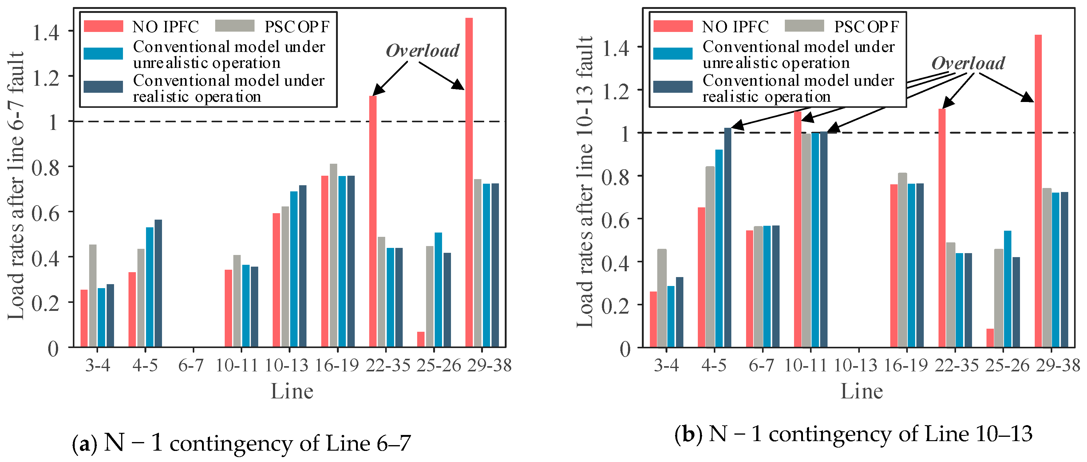
Figure 5 shows that there are risks of overload in the actual operation of the system without IPFC, while IPFC helps to regulate power flow distribution and improve the security of the system. Load violations can be eliminated after N − 1 contingencies under the proposed PSCOPF model and unrealistic conventional model. However, ignorance of IPFC control characteristics is unreasonable. Overload appears under the realistic operation, which may even lead to cascading failure in certain extreme situations. The proposed model considers the actual operation properties of IPFC, and the system is secure under all N − 1 contingencies, proving the feasibility and effectiveness of the proposed model.

4.2. Comparison with a Fixed IPFC Control Mode

To verify the importance of considering IPFC control modes, a PSCOPF model that does not consider IPFC control modes is also compared. The objective function, constraints, contingency set NC and corresponding optimization parameters keep consistent with the proposed PSCOPF model considering IPFC control modes. The only difference is that the master converter of IPFC uses the fixed and most common control mode, CPCM. After implementation in MATLAB, the optimization results of the two models are compared, as shown in Table 2.
Table 2 shows that due to the priority to satisfy the elimination of load violations, operation cost is slightly sacrificed when considering IPFC control modes. However, the PSCOPF model with the fixed CPCM control mode cannot satisfy the prerequisite to eliminate the risk of overload, and the voltage stability of the system is also worse. Therefore, it is meaningful to consider IPFC control modes in the PSCOPF optimization.
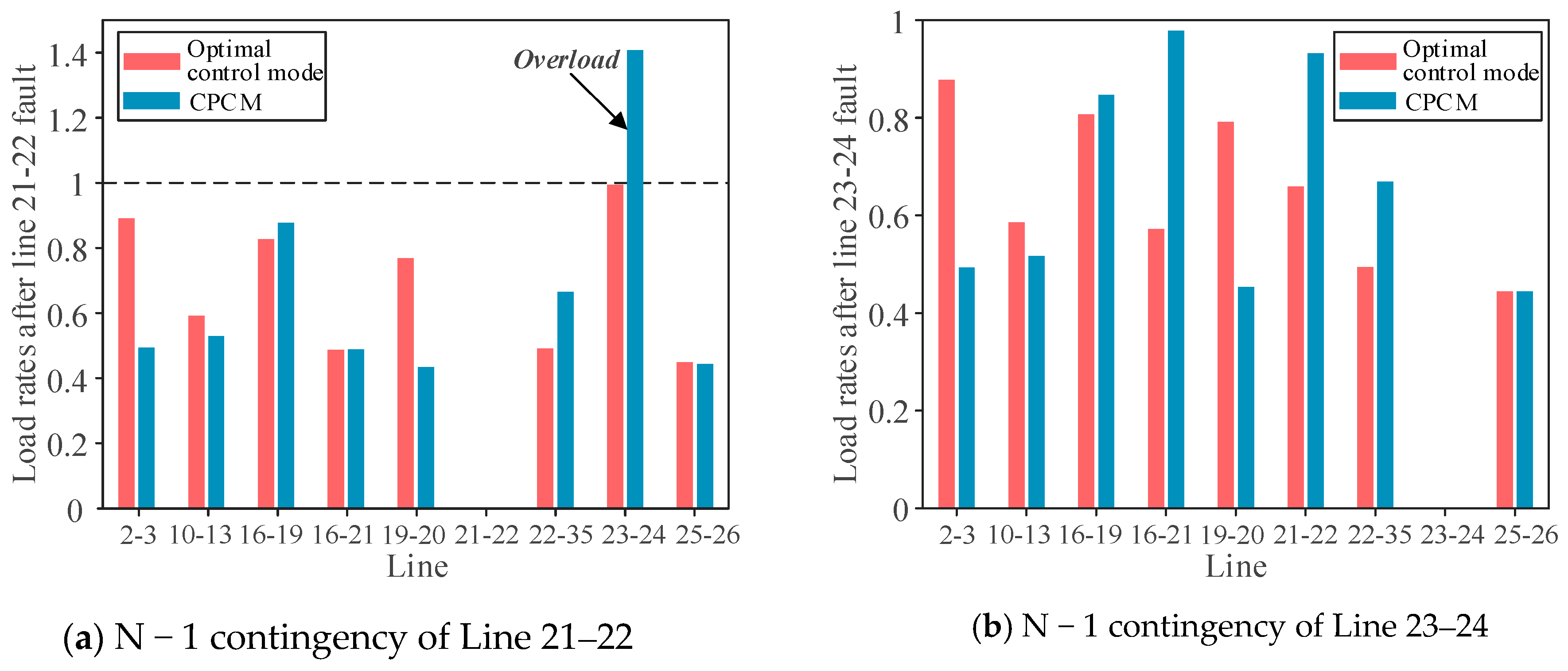
Load rates of typical transmission lines before and after considering IPFC control modes are shown in Figure 6, and compared scenarios include N − 1 contingencies of Lines 21–22 and 23–24.
In Figure 6, CPCM corresponds to the fixed IPFC control mode. The optimal control mode corresponds to the optimization results considering four control modes of the master converter and ICCM is the calculated optimal result in the tested system. ICCM reveals better performance in heavy load lines and helps to eliminate overload after N − 1 contingencies. However, load violation exists after the N − 1 contingency of line 21–22 under the fixed IPFC control mode, dissatisfying the security constraints in actual operation. The security problem can be addressed by changing to the optimal IPFC control mode without the need for additional equipment costs, proving the superiority of the proposed model considering IPFC control modes.
The power and voltages required in the objective function and constraints of the proposed model are obtained through power flow calculation. Iterative updates of converter output voltages and equivalent injected power under each IPFC control mode are utilized to obtain the required parameters and further solve the optimization model. The optimal solution of the proposed model can decrease operation cost and improve the security of the system.

5. Future Research

IPFC control modes are considered in the PSCOPF model to improve security-constrained OPF. Security is given priority in the paper, and potential overloads are avoided through the proposed model. Dynamic voltage stability as well as the transition duration of IPFC control mode switching can be considered in the optimization to avoid avalanche-like voltage decrease after emergency disturbances. After considering the dynamic process, field experiments can be conducted in hardware and then in the real power system.

6. Conclusions

A PSCOPF model considering IPFC control modes is established in this paper. It reconciles the economy and security of the system, and the preventive-security-constrained technique is involved in achieving IPFC control potential after contingencies. Constraints of the proposed model generally include power system operation constraints and IPFC operation constraints, in which IPFC control characteristics under different control modes are fully analyzed. The optimal selection of IPFC control modes and control parameters can then be obtained to improve economy and security of the system. Numerical results prove the superiority of the proposed model considering IPFC control modes, avoiding overloads under unrealistic assumption of the constant converter output voltages or fixed control modes.

Author Contributions

Conceptualization, X.W.; formal analysis, H.C. and C.H.; funding acquisition, H.C.; investigation, H.C.; project administration, X.W.; resources, H.C.; software, C.H.; supervision, X.W.; validation, C.H.; writing—original draft, C.H.; writing—review and editing, X.W. All authors have read and agreed to the published version of the manuscript.

Funding

This work was supported by Science and Technology Project of State Grid Corporation of China “Planning technologies and applications to improve the flexibility of regional power grid structures with high proportions of new energy consumption” (5100-202318036A-1-1-ZN).

Data Availability Statement

The original contributions presented in the study are included in the article, further inquiries can be directed to the corresponding author.

Conflicts of Interest

Author Hui Cai was employed by the company State Grid Jiangsu Electric Power Co., Ltd. The remaining authors declare that the research was conducted in the absence of any commercial or financial relationships that could be construed as a potential conflict of interest.

References

  1. Bavafa, F.; Niknam, T.; Azizipanah-Abarghooee, R.; Terzija, V. A New Biobjective Probabilistic Risk-Based Wind-Thermal Unit Commitment Using Heuristic Techniques. IEEE Trans. Ind. Inform. 2017, 13, 115–124. [Google Scholar] [CrossRef]
  2. Claeys, S.; Deconinck, G.; Geth, F. Voltage-dependent Load Models in Unbalanced Optimal Power Flow Using Power Cones. IEEE Trans. Smart Grid 2021, 12, 2890–2902. [Google Scholar] [CrossRef]
  3. Kumar, A.; Kumar, J. ATC Determination with FACTS Devices Using PTDFs Approach for Multi-transactions in Competitive Electricity Markets. Int. J. Electr. Power Energy Syst. 2013, 44, 308–317. [Google Scholar] [CrossRef]
  4. Jiang, S.; Gole, A.M.; Annakkage, U.D.; Jacobson, D.A. Damping Performance Analysis of IPFC and UPFC Controllers Using Validated Small-signal Models. IEEE Trans. Power Deliv. 2011, 26, 446–454. [Google Scholar] [CrossRef]
  5. Azbe, V.; Mihalic, R. The Control Strategy for an IPFC Based on the Energy Function. IEEE Trans. Power Syst. 2008, 3, 1662–1669. [Google Scholar] [CrossRef]
  6. Eremia, M.; Liu, C.C.; Edris, A.A. Interline Power Flow Controller (IPFC). In Advanced Solutions in Power Systems: HVDC, FACTS, and Artificial Intelligence; John Wiley & Sons: Hoboken, NJ, USA, 2016; pp. 638–640. [Google Scholar]
  7. Moghadasi, S.; Kazemi, A.; Firuzabad, M.F.; Edris, A. Composite System Reliability Assessment Incorporating an Interline Power-flow Controller. IEEE Trans. Power Deliv. 2008, 23, 1191–1199. [Google Scholar] [CrossRef]
  8. Jiang, X.; Chow, J.H.; Edris, A.; Fardanesh, B.; Uzunovic, E. Transfer Path Stability Enhancement by Voltage-sourced Converter-based FACTS Controllers. IEEE Trans. Power Deliv. 2010, 25, 1019–1025. [Google Scholar] [CrossRef]
  9. Mishra, A.; Kumar, G.V.N. Congestion Management of Power System with Interline Power Flow Controller Using Disparity Line Utilization Factor and Multi-objective Differential Evolution. CSEE J. Power Energy Syst. 2015, 1, 76–85. [Google Scholar] [CrossRef]
  10. Soofi, A.F.; Manshadi, S.D.; Liu, G.; Dai, R. A SOCP Relaxation for Cycle Constraints in the Optimal Power Flow Problem. IEEE Trans. Smart Grid 2021, 12, 1663–1673. [Google Scholar] [CrossRef]
  11. Vijay, K.Y.N.; Sivanagaraju, S.; Suresh, C.V. Analyzing the Effect of Dynamic Loads on Economic Dispatch in the Presence of Interline Power Flow Controller Using Modified BAT Algorithm. J. Electr. Syst. Inf. Technol. 2016, 3, 45–67. [Google Scholar] [CrossRef]
  12. Rostami, M.; Lotfifard, S. Optimal Remedial Actions in Power Systems Considering Wind Farm Grid Codes and UPFC. IEEE Trans. Ind. Inform. 2020, 16, 7264–7274. [Google Scholar] [CrossRef]
  13. Gong, L.; Wang, C.H.; Zhang, C.X.; Fu, Y. High-Performance Computing Based Fully Parallel Security-Constrained Unit Commitment with Dispatchable Transmission Network. IEEE Trans. Power Syst. 2019, 34, 931–941. [Google Scholar] [CrossRef]
  14. Yan, M.; Shahidehpour, M.; Paaso, A.; Zhang, L.; Alabdulwahab, A.; Abusorrah, A. A Convex Three-Stage SCOPF Approach to Power System Flexibility with Unified Power Flow Controllers. IEEE Trans. Power Syst. 2021, 36, 1947–1960. [Google Scholar] [CrossRef]
  15. Dawn, S.; Kumar, T.P.; Kumar, G.A.; Panda, R. An Approach for System Risk Assessment and Mitigation by Optimal Operation of Wind Farm and FACTS Devices in a Centralized Competitive Power Market. IEEE Trans. Sustain. Energy 2019, 10, 1054–1065. [Google Scholar] [CrossRef]
  16. Liu, B.; Yang, Q.; Zhang, H.; Wu, H. An Interior-point Solver for AC Optimal Power Flow Considering Variable Impedance-based FACTS Devices. IEEE Access 2021, 9, 154460–154470. [Google Scholar] [CrossRef]
  17. Wang, L.; Li, H.; Wu, C. Stability Analysis of an Integrated Offshore Wind and Seashore Wave Farm Fed to a Power Grid Using a Unified Power Flow Controller. IEEE Trans. Power Syst. 2013, 28, 2211–2221. [Google Scholar] [CrossRef]
  18. Park, B.; DeMarco, C.L. Advanced Modeling of DERs and UPFC Devices with Sparse Tableau Formulation for ACOPF. Electr. Power Syst. Res. 2019, 174, 105870. [Google Scholar] [CrossRef]
  19. Hussein, M.E.; Rabea, F.; Kamel, S.; Oda, E.S. Effective Modeling of OUPFC Into Newton-Raphson Power Flow Considering Multi-Control Modes and Operating Constraints. IEEE Access 2021, 9, 129394–129406. [Google Scholar] [CrossRef]
  20. Bhowmick, S.; Das, B.; Kumar, N. An Advanced IPFC Model to Reuse Newton Power Flow Codes. IEEE Trans. Power Syst. 2009, 24, 525–532. [Google Scholar] [CrossRef]
  21. Ding, T.; Bo, R.; Li, F.; Sun, H. Optimal Power Flow with the Consideration of Flexible Transmission Line Impedance. IEEE Trans. Power Syst. 2016, 31, 1655–1656. [Google Scholar] [CrossRef]
  22. Galvani, S.; Hagh, M.T.; Sharifian, M.B.B.; Mohammadi-Ivatloo, B. Multiobjective Predictability-Based Optimal Placement and Parameters Setting of UPFC in Wind Power Included Power Systems. IEEE Trans. Ind. Inform. 2019, 15, 878–888. [Google Scholar] [CrossRef]
  23. Singh, P.; Senroy, N.; Tiwari, R. Guaranteed Convergence Embedded System for SSSC and IPFC. IEEE Trans. Power Syst. 2021, 36, 2725–2728. [Google Scholar] [CrossRef]
  24. Naveen Kumar, G.; Surya Kalavathi, M. Cat Swarm Optimization for Optimal Placement of Multiple UPFC’s in Voltage Stability Enhancement Under Contingency. Int. J. Electr. Power Energy Syst. 2014, 57, 97–104. [Google Scholar] [CrossRef]
  25. Hou, Q.C.; Zhang, N.; Kirschen, D.S.; Du, E.; Cheng, Y.H.; Kang, C.Q. Sparse Oblique Decision Tree for Power System Security Rules Extraction and Embedding. IEEE Trans. Power Syst. 2021, 36, 1605–1615. [Google Scholar] [CrossRef]
  26. Padullaparti, H.V.; Nguyen, Q.H.; Santoso, S. Optimal Placement and Dispatch of LV-SVCs to Improve Distribution Circuit Performance. IEEE Trans. Power Syst. 2019, 34, 2892–2900. [Google Scholar] [CrossRef]
  27. Mhanna, S.; Mancarella, P. An Exact Sequential Linear Programming Algorithm for the Optimal Power Flow Problem. IEEE Trans. Power Syst. 2022, 37, 666–679. [Google Scholar] [CrossRef]
  28. Thomas, J.J.; Grijalva, S. Flexible Security-constrained Optimal Power Flow. IEEE Trans. Power Syst. 2015, 30, 1195–1202. [Google Scholar] [CrossRef]
  29. Wu, X.; Wang, R.; Wang, Y.; Wang, L. A Novel UPFC Model and its Convexification for Security-Constrained Economic Dispatch. IEEE Trans. Power Syst. 2022, 37, 4202–4213. [Google Scholar] [CrossRef]
  30. Arroyo, J.M.; Fernandez, F.J. Application of a Genetic Algorithm to N-k Power System Security Assessment. Int. J. Electr. Power Energy Syst. 2013, 49, 114–121. [Google Scholar] [CrossRef]
  31. Kessel, P.; Glavitsch, H. Estimating the Voltage Stability of a Power System. IEEE Trans. Power Deliv. 1986, 1, 346–354. [Google Scholar] [CrossRef]
  32. Wang, Y.; Wang, C.; Lin, F.; Li, W.; Wang, L.Y.; Zhao, J. Incorporating Generator Equivalent Model into Voltage Stability Analysis. IEEE Trans. Power Syst. 2013, 28, 4857–4866. [Google Scholar] [CrossRef]
  33. Zhang, Y.; Zhang, Y.; Chen, C. A Novel Power Injection Model of IPFC for Power Flow Analysis Inclusive of Practical Constraints. IEEE Trans. Power Syst. 2006, 21, 1550–1556. [Google Scholar] [CrossRef]
  34. Wu, X.; Zhou, Z.Y.; Liu, G.; Qi, W.C.; Xie, Z.J. Preventive Security-constrained Optimal Power Flow Considering UPFC Control Modes. Energies 2017, 10, 1199. [Google Scholar] [CrossRef]
  35. Engelbrecht, A.P. Particle Swarm Optimization. In Computational Intelligence: An Introduction; John Wiley & Sons: Chichester, UK, 2007; pp. 289–314. [Google Scholar]
  36. Athay, T.; Podmore, R.; Virmani, S. A Practical Method for the Direct Analysis of Transient Stability. IEEE Trans. Power Appar. Syst. 1979, PAS-98, 573–584. [Google Scholar]
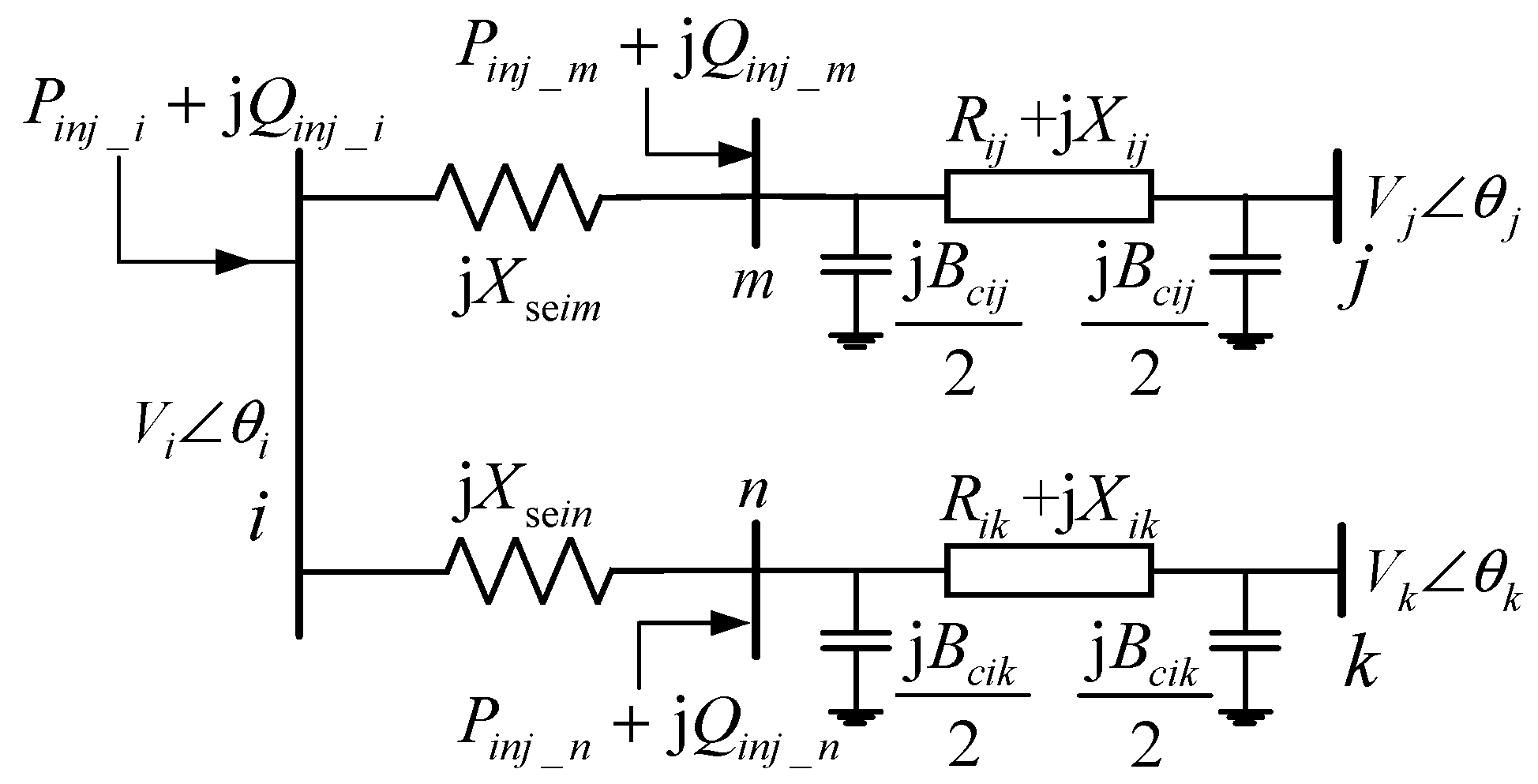
Figure 1. Equivalent IPFC model with two series branches based on the power injection model.
Energies 17 01660 g001
Figure 2. Framework of the solution method.
Energies 17 01660 g002
Figure 3. Flow chart for power flow calculation considering IPFC control modes.
Energies 17 01660 g003
Figure 4. Diagram of IEEE 39-bus New England case.
Energies 17 01660 g004
Figure 5. Comparison of load rates under different scenarios.
Energies 17 01660 g005
Figure 6. Comparison of load rates before and after considering IPFC control mode.
Energies 17 01660 g006
Table 1. Results of the PSCOPF model compared with the conventional model and the system without IPFC.
ParametersPSCOPF ModelConventional Model under Unrealistic OperationConventional Model under Realistic OperationSystem without IPFC
Objective function value7.6793 × 1047.7404 × 1041.8264 × 1073.4553 × 108
Economy function reflecting operation cost4.7546 × 1044.6786 × 1044.8213 × 1044.5613 × 104
Security function about voltage stability index1.46241.53091.67701.5155
Number of average overloaded lines (N − 1)000.18183.4545
Table 2. Results compared with optimization with a fixed IPFC control mode.
ParametersPSCOPF Model Considering IPFC Control Modes PSCOPF Model with a Fixed IPFC Control Mode
Objective function value7.6793 × 1049.1656 × 106
Control mode and corresponding control targetICCM, Zref = −0.03462 + j 0.01887p.u.CPCM, Pmjref = 2.0745p.u., Qmjref = 1.3372p.u.
Control target of the slave converterPnkref = 0.7843p.u.Pnkref = 2.0975p.u.
Economy function reflecting operation cost4.7546 × 1044.5192 × 104
Voltage stability index of the security function1.46241.4765
Number of average overloaded lines (N − 1)00.0909
Disclaimer/Publisher’s Note: The statements, opinions and data contained in all publications are solely those of the individual author(s) and contributor(s) and not of MDPI and/or the editor(s). MDPI and/or the editor(s) disclaim responsibility for any injury to people or property resulting from any ideas, methods, instructions or products referred to in the content.