
Research on Wave Energy Converters


Abstract
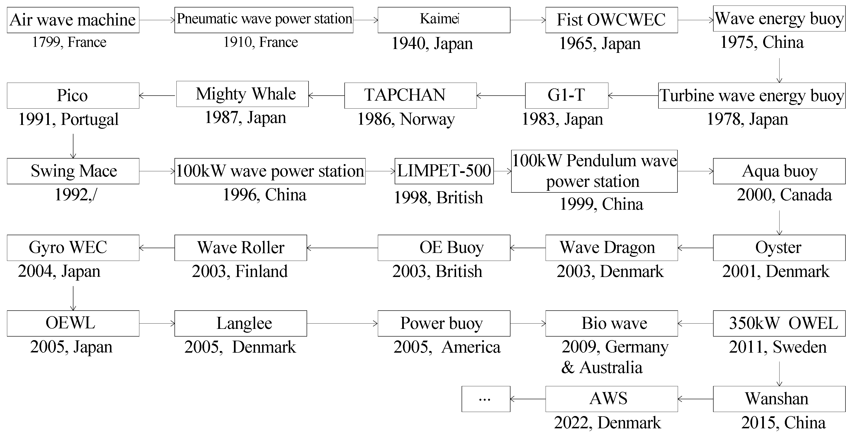
1. Introduction
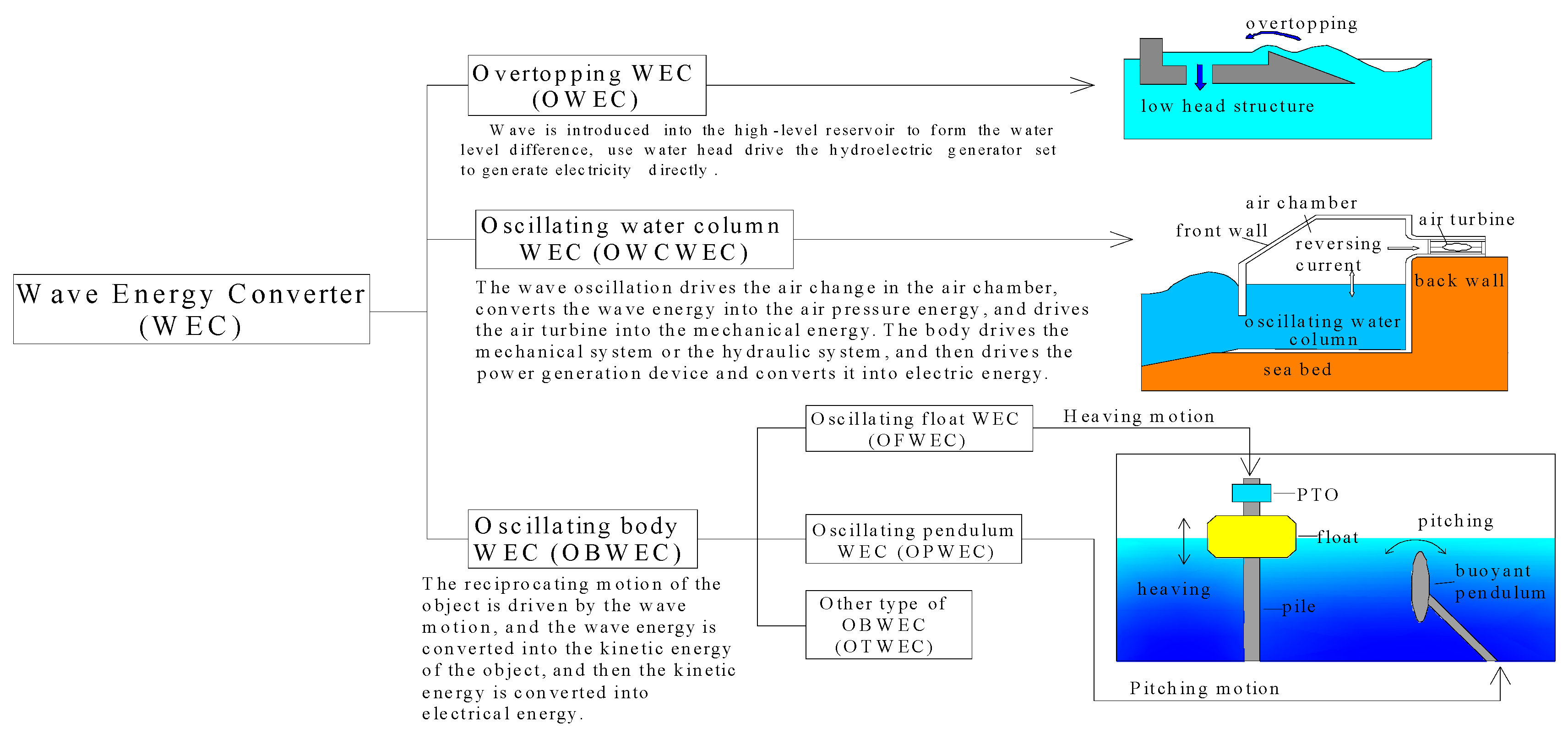
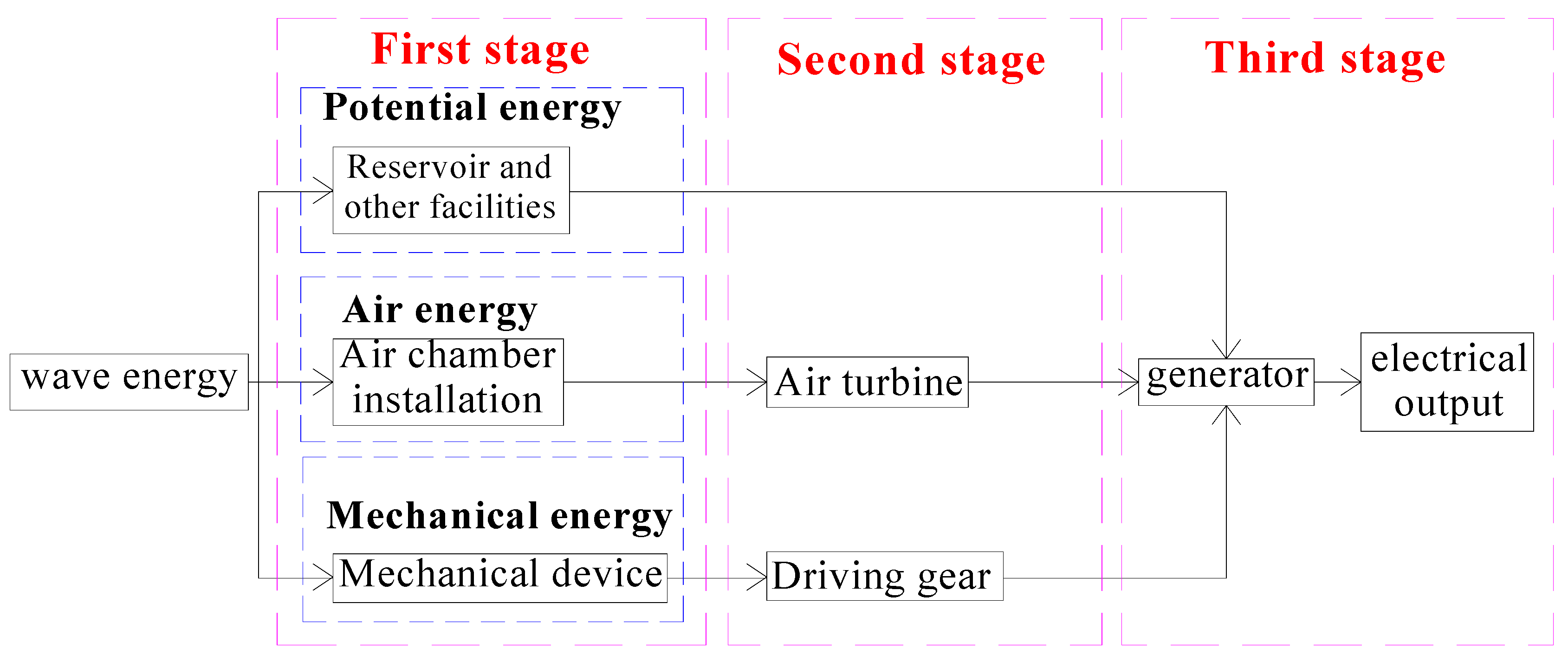
2. Classification and Working Principle of WEC
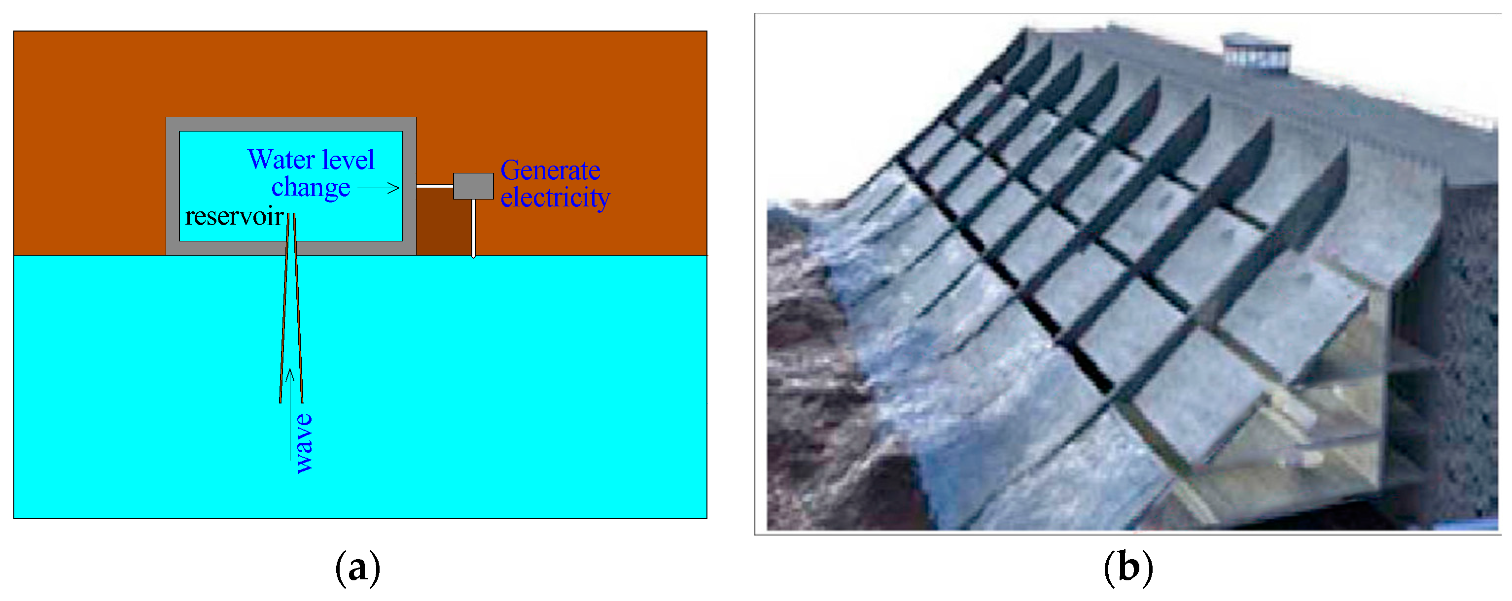
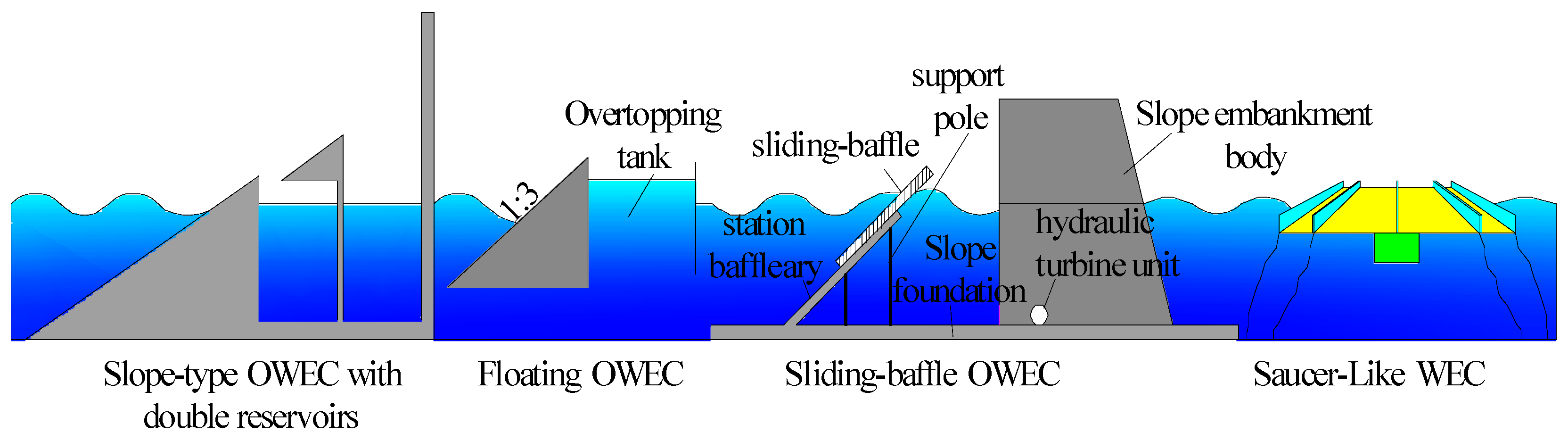
2.1. Overtopping Wave Energy Converter (OWEC)
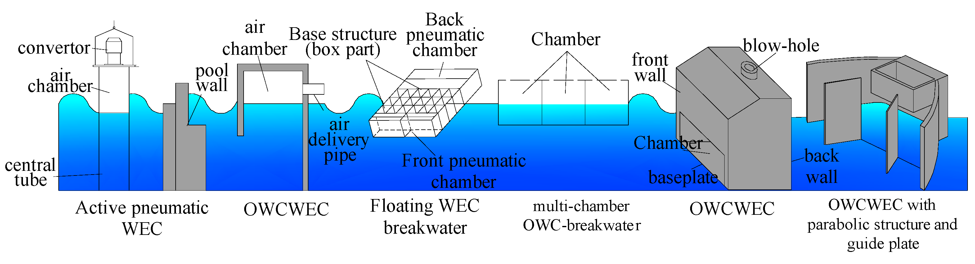
2.2. Oscillating Water Column WEC (OWCWEC)
2.3. Oscillating Body WEC (OBWEC)
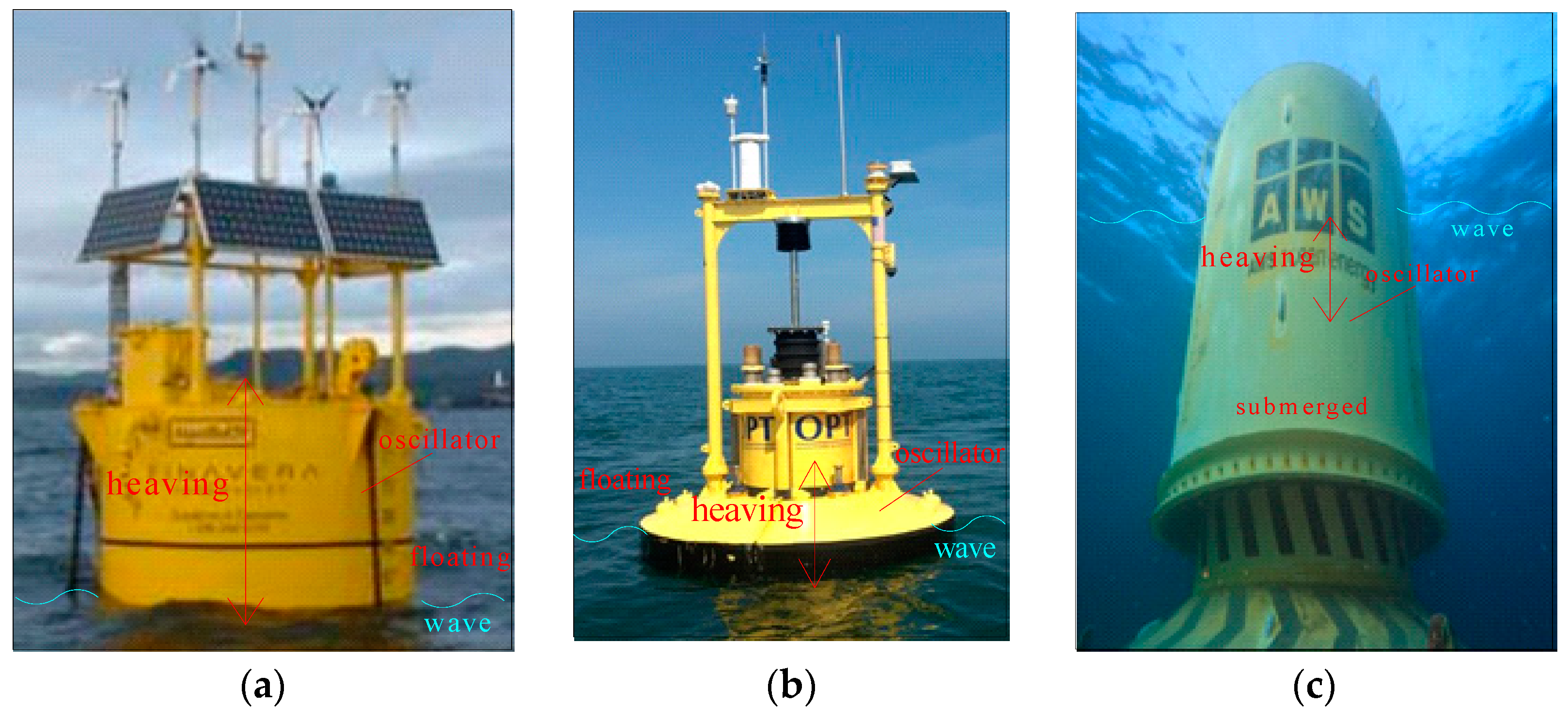
2.3.1. Oscillating Float WEC (OFWEC)
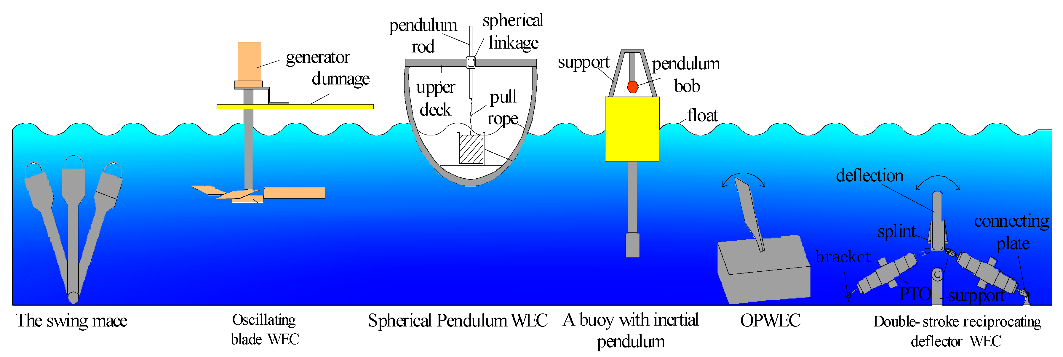
2.3.2. Oscillating Pendulum WEC (OPWEC)
2.3.3. Other Types of WEC (OTWEC)
3. Analysis and Summary
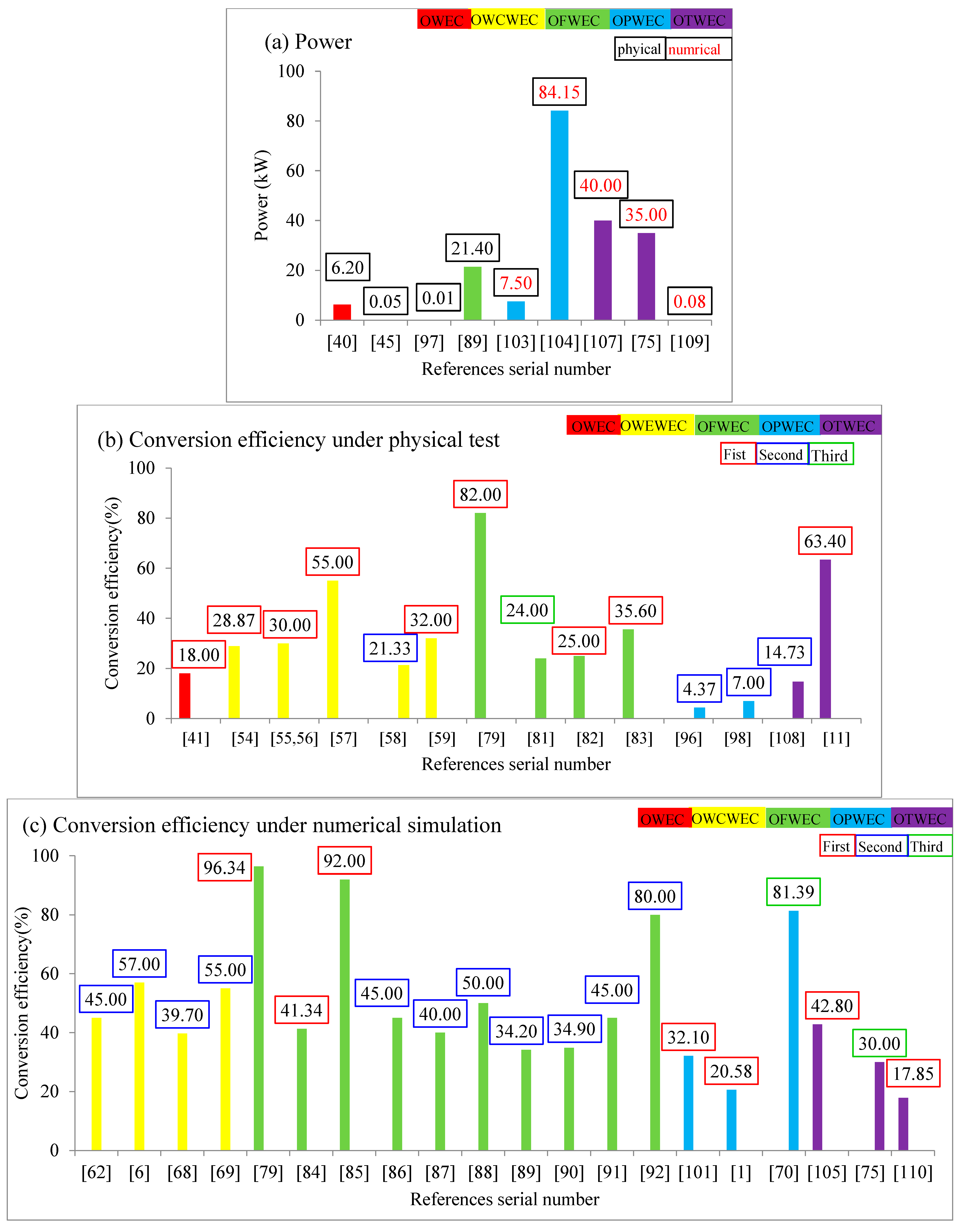
3.1. Analysis
3.2. Problems and Disadvantages
- (1)
- Fewer studies on physical experiments
- (2)
- Fewer studies on power generation efficiency
- (3)
- Lower generating efficiency
- (4)
- Lower engineering applicability
- (5)
- Greater influence on sea ecological environment
- (6)
- Greater wave force subjected
- (7)
- Less information about current WEC engineering
- (8)
- High cost
- (9)
- Lack of standards and norms
3.3. Prospect
4. Conclusions
- (1)
- It can be seen that the comprehensive performance of OBWEC is better, and the power generation efficiency under the test condition reached 21.33%.
- (2)
- The numerical simulation or theoretical research on wave energy power generation devices is relatively important, and it is hoped to conduct more physical experiment research.
- (3)
- There are many studies on primary or secondary efficiency conversion of WECs, and it is suggested to increase the research on power generation efficiency.
- (4)
- It is hoped that wave energy discovery devices will continue to be developed with higher power generation efficiency and less wave load.
Author Contributions
Funding
Data Availability Statement
Conflicts of Interest
Nomenclature
| T | Period of the wave, s |
| h | depth of water, m |
| H | height of the wave, m |
| L | length of the wave, m |
| ω | wave angular frequency, rad/s |
| γ | JONSWAP spectral shape factor |
| η1 | captured energy efficiency, % |
| η2 | second stage conversion efficiency, % |
| η | third stage (generating efficiency), % |
| Abbreviations | |
| WEC | wave energy converter |
| OWEC | overtopping WEC |
| OWCWEC | oscillating water column WEC |
| OBWEC | oscillating body WEC |
| OFWEC | oscillating float type WEC |
| OPWEC | oscillating pendulum wave WEC |
| OTWEC | other type of OBWEC |
| PTO | power take-off |
References
- Fan, M.; Zhao, J.; Jia, Y.; Wei, Y.; Wang, J. Analysis of energy capture characteristics of buoyancy oscillating wave power generation convertor. China Shiprep. 2020, 33, 51–55. [Google Scholar]
- Zhang, Y.; Yu, H. Development of experimental teaching platform for ocean wave power generation based on multi-energy harvesting principle. Exp. Technol. Manag. 2018, 35, 22–25. [Google Scholar] [CrossRef]
- Lindroth, S.; Leijon, M. Offshore wave power measurements–A review. Renew. Sustain. Energy Rev. 2011, 15, 4274–4285. [Google Scholar] [CrossRef]
- Dalton, G.J.; Alcorn, R.; Lewis, T. Case study feasibility analysis of the Pelamis wave energy convertor in Ireland, Portugal and North America. Renew. Energy 2010, 35, 443–455. [Google Scholar] [CrossRef]
- Chinese Journal of Science. “Wan Shan” Eagle Wave Power Generation Device Successfully Generated Electricity. 2015. Available online: https://www.eworldship.com/html/2015/OperatingShip_1126/109190.html (accessed on 20 November 2023).
- Xiu, W. Study on the Aerodynamic Performance of Impulse Turbine Used in Wave Energy. Unpublished MA Dissertation, Kunming University of Science and Technology, Kunming, China, 2021. [Google Scholar] [CrossRef]
- Ross, D. Power from Sea Waves; Count, B., Ed.; Oxford University Press: Oxford, UK, 1995; pp. 10–11. [Google Scholar]
- Masuda, Y.; McCormick, M.E. Experiences in pneumatic wave energy conversion in Japan. In Coastal Engineering; ASCE: Reston, VA, USA, 1986; pp. 1–33. [Google Scholar]
- Zhang, Y.; Zhao, Y.; Sun, W.; Li, J. Ocean wave energy converters: Technical principle, device realization, and performance evaluation. Renew. Sustain. Energy Rev. 2021, 141, 110764. [Google Scholar] [CrossRef]
- Wu, Y.; Zhigang, B.; Haitao, Y.; Xuan, M..; Ying, Z.; Cheng, C.; Lei, D. Flexible capsule model tests on the ocean wave energy generation system. Ocean. Eng. 2016, 34, 101–108. [Google Scholar]
- Hirohisa, T. Sea trial of a heaving buoy wave power absorber. In Proceedings of the 2nd International Symposium on Wave Energy Utilization, Trondheim, Norway, 15–17 June 1982; pp. 403–417. [Google Scholar]
- Mawooa, D.; Latchoomun, L.; Kaully, R.G.; Busawon, K. An overview of wave energy technologies in the Mauritian context. In Proceedings of the 2018 5th International Symposium on Environment-Friendly Energies and Applications (EFEA), Rome, Italy, 24–26 September 2018; pp. 1–6. [Google Scholar]
- Washio, Y.; Osawa, H.; Nagata, Y.; Fujii, F.; Furuyama, H.; Fujita, T. The offshore floating type wave power device “Mighty Whale”: Open sea tests. In Proceedings of the ISOPE International Ocean and Polar Engineering Conference, Seattle, WA, USA, 27 May–2 June 2000; ISOPE: Mountain View, CA, USA, 2000; p. ISOPE-I. [Google Scholar]
- Lagoun, M.S.; Benalia, A.; Benbouzid, M.E.H. Wave electric power generation technologies: State of the art and current status. In Proceedings of the 1st International Symposium on Environment Friendly Energies in Electrical Applications, Manama, Bahrain, 18–22 December 2010. [Google Scholar]
- Salter, S.H. The swinging mace. In Proceedings of the Workshop Wave Energy R&D, Cork, Ireland, 6–10 July 1992; pp. 197–206. [Google Scholar]
- Health, T.; Whittaker, T.J.T.; Boake, C.B. The design, construction and operation of the LIMPET wave energy converter (Islay, Scotland). In Proceedings of the 4th European Wave Energy Conference, Aalborg, Denmark, 4–6 December 2000; pp. 49–55. [Google Scholar]
- WAVE ENERGY: Aquabuoy 2.0 Wave Power Generator. 2007. Available online: https://inhabitat.com/wave-energy-aquabuoy-20-wave-power-generator/ (accessed on 20 November 2023).
- Fadaeenejad, M.; Shamsipour, R.; Rokni, S.D.; Gomes, C. New approaches in harnessing wave energy: With special attention to small islands. Renew. Sustain. Energy Rev. 2014, 29, 345–354. [Google Scholar] [CrossRef]
- Kofoed, J.P.; Frigaard, P.; Friis-Madsen, E.; Sorensen, H.C. Prototype testing of the wave energy converter wave dragon. Renew. Energy 2006, 31, 181–189. [Google Scholar] [CrossRef]
- Shen Du Shi Xun: Xisha Yongxing Island Set Up ‘Pilot No.1’ Wave Energy Power Generation Device! Provide Clean Energy for the Island. 2019. Available online: http://www.360doc.com/content/19/0526/20/30724179_838375575.shtml (accessed on 20 November 2023).
- Franzitta, V.; Colucci, A.; Curto, D.; Di Dio, V.; Trapanese, M. A linear generator for a waveroller power device. In Proceedings of the OCEANS 2017, Aberdeen, Scotland, 19–22 June 2017; pp. 1–5. [Google Scholar]
- Liu, Y. Gyro-type wave power generation system. Popularelectricity 2015, 56, 53. [Google Scholar]
- Pecher, A.; Kofoed, J.P.; Weisz, A. Experimental Study on the Langlee Wave Energy Converter. Unpublished MA Dissertation, Department of Civil Engineering, Aalborg University, Aalborg, Denmark, 2009. [Google Scholar]
- Ocean News. Eni Deploys Ocean Power Technologies’ PowerBuoy™ in the Adriatic Sea. 2018. Available online: https://www.oceannews.com/news/energy/eni-deploys-ocean-power-technologies-powerbuoy-in-the-adriatic-sea. (accessed on 20 November 2023).
- Dai, Y.; Chen, Y.; Xie, L. A study on a novel two-body floating wave energy converter. Ocean. Eng. 2017, 130, 407–416. [Google Scholar] [CrossRef]
- AWS: AWS Wave Swing Trials Exceed Expectations. 2022. Available online: https://awsocean.com/2022/11/aws-waveswing-trials-exceed-expectations/ (accessed on 20 November 2023).
- Han, B.F.; Chu, J.K.; Xiong, Y.S.; Yao, F. Progress of Research on Ocean Wave Energy Power Generation. Power Syst. Clean Energy 2012, 28, 6. [Google Scholar]
- Wang, L.; You, Y.; Zhang, Y. Research Status of the Power Take-off System for Wave Energy Converters. Mach. Tool Hydraul. 2013, 41, 165–168. [Google Scholar]
- Liu, D.; Zheng, Y.; Zhang, J. Research and application prospects of oscillating water column converter. J. Dalian Ocean. Univ. 2015, 30, 6. [Google Scholar]
- Chen, R.; Liu, C.; Zhang, Y. Research Status and Perspective of Direct Ocean Wave Energy Harvesters. J. Data Acquis. Process. 2019, 34, 195–204. [Google Scholar]
- Shi, H.; Liu, Z. Research status and development tendency of ocean wave energy. Sci. Technol. Rev. 2021, 39, 22–28. [Google Scholar]
- Chen, J.; Lan, F.; Guo, H.; Li, J. Review of wave energy power generation control technology research. Electr. Power Autom. Equip. 2023, 43, 124–136. [Google Scholar]
- Sun, C.; Shang, J.; Luo, Z.; Lu, Z.; Wang, R. A review of wave energy extraction technology. In IOP Conference Series: Materials Science and Engineering; IOP Publishing: Bristol, UK, 2018; Volume 394, p. 042038. [Google Scholar]
- Triasdian, B.; Indartono, Y.S.; Ningsih, N.S.; Novitasari, D. Device Selection of the Potential Wave Energy Site in Indonesian Seas. In IOP Conference Series: Earth and Environmental Science; IOP Publishing: Bristol, UK, 2019; Volume 291, p. 012040. [Google Scholar]
- JBao, J.; Xu, C.; Yang, X. Experimental study on wave force of U-shaped oscillating water column wave energy generation device. China Water Transp. Second Half Mon. 2020, 20, 65–66+157. [Google Scholar]
- He, J.; Fan, R. Structural design of floating bucket wave energy power generation system. In Proceedings of the 2022 International Conference on Wireless Communications, Electrical Engineering and Automation (WCEEA), Indianapolis, IN, USA, 15–16 October 2022; pp. 29–32. [Google Scholar]
- Vicinanza, D.; Margheritini, L.; Kofoed, J.P.; Buccino, M. The SSG wave energy converter: Performance, status and recent developments. Energies 2012, 5, 193–226. [Google Scholar] [CrossRef]
- Lagstroem, G.; Lagstroem, G. Sea Power international—floating wave power vessel, FWPV. In Wave Power Moving towards Commercial Viability; Institution ofMechanical Engineers Seminar: London, UK, 1999. [Google Scholar]
- Huang, Y.; Shi, H.D.; Liu, Z. Experimental Study of the Overtopping Performance on Saucer-Like Wave Energy Convertor. Period. Ocean. Univ. China 2011, 41, 93–98. [Google Scholar]
- Huang, Y.; Shi, H.; Liu, Z. A Systematic Study on Saucer-Like Wave Energy Converter. Coast. Eng. 2012, 31, 33–39. [Google Scholar]
- Chen, B.; Yang, Z.; Tom, B. Hydraulic characteristics study of an overtopping wave energy converter. Renew. Energy Resour. 2013, 31, 6. [Google Scholar]
- Yang, Z.; Liu, X. The Experimental Study on Overtopping Discharge and Wave Pressure of an Overtopping Wave Energy Converter. Coast. Eng. 2016, 35, 63–73. [Google Scholar]
- Xu, G.; Ji, J.; Qu, H.; Liu, Z. An Experimental Study on Structural Stress of Slope-type OWEC of Double Reservoirs. Coast. Eng. 2017, 36, 48–57. [Google Scholar]
- Ma, S.; Pan, X.; Liang, B. 2D numerical simulation of layered slope-type overtopping wave energy generation device. Acta Energiae Solaris Sin. 2017, 38, 2904–2908. [Google Scholar]
- Hur, D.S.; Jeong, Y.M.; Lee, J.L.; Kim, I.H.; Lee, W.D. Energy generation efficiency due to wave overtopping on floating-overflow-type wave energy converter. J. Coast. Res. 2018, 85, 1341–1345. [Google Scholar] [CrossRef]
- Liu, Y.; Liu, Z.; Hyum, B.S.; Hong, K.Y.; Ji, J. 2D Numerical study on overtopping wave energy convertor. J. Hydroelectr. Eng. 2012, 31, 7. [Google Scholar]
- You, Z.; Ge, K.; Sheng, C.; Huang, X. Force study of sliding-baffle type wave overtopping power generation device. Acta Energiae Solaris Sin. 2017, 38, 1699–1705. [Google Scholar]
- Liu, D.; Liu, Z.; Zhang, G. 3D Numerical Simulation of the Overtopping Performance of Circular Ramp Wave Energy Convertor. Coast. Res. 2020, 39, 237–245. [Google Scholar]
- Torre-Enciso, Y.; Ortubia, I.; De Aguileta, L.L.; Marqués, J. Mutriku wave power plant: From the thinking out to the reality. In Proceedings of the 8th European Wave and Tidal Energy Conference, Uppsala, Sweden, 7–11 September 2009; Volume 710, pp. 319–329. [Google Scholar]
- Heath, T.V. The development of a turbo-generation system for application in OWC breakwaters. In Proceedings of the 7th European Wave and Tidal Energy Conference, Porto, Portugal, 11–13 September 2007. [Google Scholar]
- Gomes, R.P.F.; Henriques, J.C.C.; Gato, L.M.C.; Falcão, A.D.O. Hydrodynamic optimization of an axisymmetric floating oscillating water column for wave energy conversion. Renew. Energy 2012, 44, 328–339. [Google Scholar] [CrossRef]
- Rea, J.; Kelly, J.; Alcorn, R.; O’Sullivan, D. Development and operation of a power take off rig for ocean energy research and testing. In Proceedings of the 9th European Wave and Tidal Energy Conference, Southampton, UK, 5–9 September 2011. [Google Scholar]
- Gao, X.; Jiang, N.; Liang, X. An Experimental Facility for Simulating Pneumatic Wave-Energy Conversion by Active Model in Static Pond. Coastal Res. 1983, 01, 84–91. [Google Scholar]
- Shi, H.; Shang, R.; Liu, Z.; Jiao, J. Owc Experimental Study on Pressure Drop of the Impulse Turbine of OWC. Period. Ocean. Univ. China 2012, 42, 113–119. [Google Scholar]
- He, F.; Huang, Z.; Law, A.W.K. An experimental study of a floating breakwater with asymmetric pneumatic chambers for wave energy extraction. Appl. Energy 2013, 106, 222–231. [Google Scholar] [CrossRef]
- He, F.; Leng, J.; Zhao, X. An experimental investigation into the wave power extraction of a floating box-type breakwater with dual pneumatic chambers. Appl. Ocean. Res. 2017, 67, 21–30. [Google Scholar] [CrossRef]
- Zhao, X.; Zhang, L.; Li, M.; Johanning, L. Experimental investigation on the hydrodynamic performance of a multi-chamber OWC-breakwater. Renew. Sustain. Energy Rev. 2021, 150, 111512. [Google Scholar] [CrossRef]
- Meng, Z.; Ding, Y.; Chen, Y.; Li, S. Experimental study on heave performance of a new wave energy power generation device based on regular waves. Ocean. Eng. 2022, 252, 111099. [Google Scholar] [CrossRef]
- Fan, C. Experimental study on conversion efficiency of caisson as OWC device. China Water Transp. Second. Half Mon. 2016, 16, 288–292. [Google Scholar]
- Shi, H.; Liu, H.; Liu, Z. Numerical Analysis of Wave Field in OWC Chamber Using VOF Model. Period. Ocean. Univ. China 2009, 39, 526–530. [Google Scholar]
- Liu, Z.; Shi, H.; Xiong, C. Analysis of an Impulse Turbine in an OWC (Ocean Wave Converter) Wave Energy Device. J. Eng. Therm. Energy Power 2009, 24, 105–108. [Google Scholar]
- Liu, Z.; Shi, H.; Hyun, B. Numerical simulation investigation on the impulse turbine for the oscillating water column wave power conversion device. Acta Aerodyn. Sin. 2009, 27, 352–357. [Google Scholar]
- Ji, J.; Liu, Z.; Ji, L. 3D Numerical Simulation for Oscillating Water Column Chamber in Wave-power Convertor. Coast. Res. 2011, 30, 8–12. [Google Scholar]
- Du, X.; Zhao, J.; Zhang, Y.; Zhu, W.; Wen, A.; Zhao, J. Analysis on the Hydrodynamic Pressure in the OWC Air Chamber for Wave Energy Harvesting. J. Ocean. Technol. 2016, 35, 81–86. [Google Scholar]
- Du, X.; Zhao, J.; Zhang, Y.; Zhu, W.; Zeng, Q. Theoretical Research on the Air Pressure in Oscillation Water Column Chamber for the Wave Energy Conversion System. Period. Ocean. Univ. China 2017, 47, 135–141. [Google Scholar]
- Du, X.; Liu, X.; Wang, G.; Zhu, S.; Zhao, Y. CFD Analysis of Oscillating Water Column Power Generation System Based on Piezoelectric Effect. Piezoelectrics Acoustooptics 2019, 41, 5. [Google Scholar]
- Wang, Y.; Yin, G.; Yin, S.; Yu, J.; Li, Q. Optimization of the Wave Energy Collection Structure in Oscillating Water Column Type Wave Power Generation Device. Hydropower New Energy 2022, 36, 27–32. [Google Scholar]
- Yang, X.; Liu, Z.; Zhang, X. Numerical study on a radial air turbine for the oscillating water column wave energy system. Ocean. Eng. 2021, 39, 8. [Google Scholar]
- ZZhang, Z.; Liu, Z.; Zhang, X. Numerical Study on Optimization of Impulse Air Turbines for OWC Wave Energy Conversion. Coast. Res. 2021, 40, 9. [Google Scholar]
- Chuang, D. Study on A New Double-Stroke Reciprocating Deflector Wave Energy Convertor. Unpublished MA Dissertation, Guilin University of Electronic Technology, Guilin, China, 2022. [Google Scholar] [CrossRef]
- Budal, K.; Falnes, J.; Iversen, L.C.; Lillebekken, P.M.; Oltedal, G.; Hals, T.; Onshus, T.; Høy, A.S. The Norwegian wave-power buoy project. In Proceedings of the 2nd International Symposium on Wave Energy Utilization, Trondheim, Norway, 22–24 June 1982; pp. 323–344. [Google Scholar]
- Waters, R.; Stålberg, M.; Danielsson, O.; Svensson, O.; Gustafsson, S.; Strömstedt, E.; Eriksson, M.; Sundberg, J.; Leijon, M. Experimental results from sea trials of an offshore wave energy system. Appl. Phys. Lett. 2007, 90, 90–93. [Google Scholar] [CrossRef]
- Elwood, D.; Schacher, A.; Rhinefrank, K.; Prudell, J.; Yim, S.; Amon, E.; Brekken, T.; von Jouanne, A. Numerical modeling and ocean testing of a direct-drive wave energy device utilizing a permanent magnet linear generator for power take-off. In Proceedings of the International Conference on Offshore Mechanics and Arctic Engineering, Honolulu, HI, USA, 31 May–6 June 2009; Volume 43444, pp. 817–824. [Google Scholar]
- Edwards, K.; Mekhiche, M. Ocean power technologies powerbuoy®: System-level design, development and validation methodology. In Proceedings of the 2nd Marine Energy Technology Symposium, Seattle, WA, USA, 15–18 April 2014. [Google Scholar]
- Fei, Y. Study on the Coupled Motion and Performance of Mushroom Wave Energy Conversion. Unpublished MA Dissertation, Harbin Engineering University, Harbin, China, 2019. [Google Scholar] [CrossRef]
- Lendenmann, H.; Strømsem, K.C.; Dai Pre, M.; Arshad, W.; Leirbukt, A.; Tjensvoll, G.; Gulli, T. Direct generation wave energy converters for optimized electrical power production. In Proceedings of the 7th European Wave Tidal Energy Conference, Porto, Portugal, 11–13 September 2007. [Google Scholar]
- Bai, Z.; Li, N.; Li, J. Construction, installation and offshore test of hydraulic buoy wave energy generation device. China Sci. Technol. Overv. 2015, 13, 70–71. [Google Scholar]
- Qingdao News: Qingdao Wave Power Breakthrough the First Batch of Residents Will Use Green Energy. 2014. Available online: http://news.qingdaonews.com/qingdao/2014-01/19/content_10237624_all.htm (accessed on 20 November 2023).
- Madhi, F.; Sinclair, M.E.; Yeung, R.W. The “Berkeley Wedge”: An asymmetrical energy-capturing floating breakwater of high performance. Mar. Syst. Ocean. Technol. 2014, 9, 5–16. [Google Scholar] [CrossRef]
- Zheng, X.; Zhang, L.; Jiang, J.; Ma, Y. Movement and Energy Conversion Performance of the Wave Energy Device. Sci. Technol. Rev. 2014, 32, 15–18. [Google Scholar]
- Ning, D.; Zhao, X.; Göteman, M.; Kang, H. Hydrodynamic performance of a pile-restrained WEC-type floating breakwater: An experimental study. Renew. Energy 2016, 95, 531–541. [Google Scholar] [CrossRef]
- Shi, H.; Qu, N.; Cao, F.; Han, G. Underactuated AUV Systems Optimal Disturbance Rejection Control with Disturbances. Period. Ocean. Univ. China 2017, 47, 124–130+145. [Google Scholar]
- Xiao, L.; Shuling, C. Experiment research on oscillating floater wave energy capture devices. J. Jiangsu Univ. Sci. Technol. Nat. Sci. Ed. 2019, 9–17. [Google Scholar]
- Mao, L.; Zhang, J.; Qu, Q.; He, H. Research and analysis of oscillating wave energy power generation device in South China Sea. Ocean. Dev. Manag. 2013, 30, 22–26. [Google Scholar]
- Zhang, H.; Zhou, B.; Vogel, C.; Willden, R.; Zang, J.; Zhang, L. Hydrodynamic performance of a floating breakwater as an oscillating-buoy type wave energy converter. Appl. Energy 2020, 257, 113996. [Google Scholar] [CrossRef]
- Chen, Q.; Zang, J.; Birchall, J.; Ning, D.; Zhao, X.; Gao, J. On the hydrodynamic performance of a vertical pile-restrained WEC-type floating breakwater. Renew. Energy 2020, 146, 414–425. [Google Scholar] [CrossRef]
- Ji, Q.; Xu, C.; Jiao, C. Numerical investigation on the hydrodynamic performance of a vertical pile-restrained reversed L type floating breakwater integrated with WEC. Ocean. Eng. 2021, 238, 109635. [Google Scholar] [CrossRef]
- Zhao, X.; Ning, D.; Zhang, C.; Kang, H. Hydrodynamic investigation of an oscillating buoy wave energy converter integrated into a pile-restrained floating breakwater. Energies 2017, 10, 712. [Google Scholar] [CrossRef]
- Zhang, X.; Zeng, Q.; Liu, Z. Hydrodynamic performance of rectangular heaving buoys for an integrated floating breakwater. J. Mar. Sci. Eng. 2019, 7, 239. [Google Scholar] [CrossRef]
- Ma, Z.; Mao, Y.; Cheng, Y.; Zhai, G. Effect of the PTO dam** force on the 2D oscillating buoy wave energy converter integrated into a pile-restrained floating breakwater. Iran. J. Sci. Technol. Trans. Mech. Eng. 2020, 44, 961–973. [Google Scholar] [CrossRef]
- Cheng, Y.; Fu, L.; Dai, S.; Collu, M.; Ji, C.; Yuan, Z.; Incecik, A. Experimental and numerical investigation of WEC-type floating breakwaters: A single-pontoon oscillating buoy and a dual-pontoon oscillating water column. Coast. Eng. 2022, 177, 104188. [Google Scholar] [CrossRef]
- Zhou, B.; Zhang, Q.; Jin, P.; Li, Y.; Liu, Y.; Zheng, S.; Ning, D. Geometric asymmetry in the energy conversion and wave attenuation of a power-take-off-integrated floating breakwater. Ocean. Eng. 2022, 246, 110576. [Google Scholar] [CrossRef]
- He, G.; Wang, P.; Liu, C.; Luan, Z. Establishment of load matching model of an oscillating float type wave energy power generation device. J. Vib. Shock 2022, 41, 55–62. [Google Scholar]
- Yan, H. Research on the optimization of the buoy quality of the oscillating buoy wave energy power generation device. China Water Transp. Second. Half Mon. 2017, 7, 263–265. [Google Scholar]
- Rahmati, M.T.; Aggidis, G.A. Numerical and experimental analysis of the power output of a point absorber wave energy converter in irregular waves. Ocean. Eng. 2016, 111, 483–492. [Google Scholar] [CrossRef]
- Li, B.; Li, G.; Liu, J.; Yang, S.; Ying, X. Research on application of wave energy generating device of oscillating blade type to ship. J. Water Resour. Water Eng. 2015, 26, 137–141. [Google Scholar]
- Song, W.J.; Shi, H.D.; Liu, P. Simulation of Oscillating Buoy Wave Energy Generation system Based on Double-Stroke Hydraulic Transmission. Acta Energiae Solaris Sin. 2016, 37, 256–260. [Google Scholar]
- Shi, H.; Li, X.; Zhao, C.; Huang, B.; Tao, J.; Zhang, Y. Hydrodynamic Study on Eccentric Pendulum Wave Energy Converter. Acta Energiae Solaris Sin. 2020, 41, 296–301. [Google Scholar]
- Wang, D.; Gou, Y. Numerical Simulation Study on Electric Power Parameters of Pelamis Wave Energy Converter. Port Eng. Technol. 2015, 52, 68–72. [Google Scholar]
- Yu, N.; Zhan, L.; Chen, W.; Zhang, Q. Spherical Pendulum Wave Power Generating Device. Mach. Des. Manuf. 2018, 4, 200–202. [Google Scholar]
- Wang, D.; Wang, Y.; Qiu, S.; Liu, K.; Ye, J.; Liang, F. Hydrodynamics of a buoy with inertial pendulum power generation device. Mach. Des. Manuf. 2019, 23, 420–429. [Google Scholar]
- Yao, T.; Wang, Z.; Zhang, X.; Wang, Y. Numerical Study on the Fluid-Structure Interaction of Wave Energy Power Direct Driven by Bottom-Hinged Flap. J. Ocean. Technol. 2020, 39, 72–78. [Google Scholar]
- Aminuddin, J.; Effendi, M.; Nurhayati, N.; Widiyani, A.; Razi, P.; Wihantoro, W.; Aziz, A.N.; Abdullatif, R.F.; Sunardi, S.; Bilalodin, B.; et al. Numerical analysis of energy converter for wave energy power generation-pendulum system. Int. J. Renew. Energy Dev. 2020, 9, 255–261. [Google Scholar] [CrossRef]
- Fan, H.; Liang, S.; Han, S.; Huang, J. Performance Of Flap-Type Wave Energy Converter Inirregular Waves. Acta Energiae Solaris Sin. 2022, 43, 82. [Google Scholar]
- Qu, Q.; He, H.; Zhang, J.; Li, H. Numerical simulation of buoy system in floating and pendular-type wave energy converter. J. Hydroelectr. Eng. 2014, 33, 221–227. [Google Scholar]
- Qu, Q.Y.; He, H.Z.; Li, H. Floating & pendular type wave energy converter. Ocean. Eng. 2013, 31, 82–88. [Google Scholar]
- Zheng, S.M.; Zhang, Y.L. Study on the wave power absorption of a raft-typed wave energy collector. J. Eng. Heilongjiang Univ. 2014, 5, 7–13. [Google Scholar]
- Fang, Z.F.; Ma, Z.H.; Fang, J.; Gao, S.; He, K.D. Research and development of multi section floating mechanical wave energy power generation device. Appl. Mech. Mater. 2014, 494, 711–716. [Google Scholar] [CrossRef]
- Chen, Y.; Huang, J.; Lin, Y.; Chen, W. Research on hydrodynamic analysis and energy capture of raft wave power generation device. China Water Transp. Second. Half Mon. 2020, 20, 98–100+107. [Google Scholar]
- Chen, Z.; Ji, C.; Guo, J.; Bian, X. Performance Investigation of an Integrated Device of Oscillating Buoy Wave Energy Converter and Floating Breakwater. Ship Eng. 2021, 43, 22–30. [Google Scholar]
- Flocard, F.; Finnigan, T.D. Experimental investigation of power capture from pitching point absorbers. In Proceedings of the Eight European Wave and Tidal Energy Conference, Uppsala, Sweden, 7–11 September 2009. [Google Scholar]
- Chongwei, Z. Analysis of Wave Energy and Offshore Wind Energy Resources. Unpublished Ph.D. Dissertation, National University of Defense Technology, Changsha, China, 2018. [Google Scholar] [CrossRef]
- Dacheng Education Library. Analysis of Wave Energy Power Generation Prospects and Power Generation Devices at Home and Abroad. Available online: http://www.360doc.com/content/20/0827/19/31655491_932536704.shtml (accessed on 20 November 2023).


| Name | Location | Category | Capacity (kW) | Date |
|---|---|---|---|---|
| IPS buoy [3] | Sweden | OWCWEC | 17 | 1980, 1981 |
| N2 buoy [3] | Norway | OWCWEC | - | 1981, 1982 |
| Swedish hose-pump [3] | Sweden | OBWEC | 30 | 1983–1984 |
| Kaiyo [3] | Japan | OBWEC | 1, 5, 10 | 1984 |
| Kaimei [3] | Japan | OWCWEC | 185 | 1985 |
| TAPCHAN [12] | Norway | OWEC | 350 | 1986 |
| BBDB [3] | Japan | OWCWEC | 5 | 1996 |
| Might Whale [3] | Japan | OWCWEC | 120 | 1998 |
| Pico [14] | Portugal | OWCWEC | 400 | 2000 |
| LIMPET [32] | UK | OWCWEC | 500 | 2001 |
| Mutuku [49] | Spain Norway | OWCWEC | 300 | 2001 |
| Wave Dragon [3] | Denmark | OWEC | 20 | 2003 |
| Lyselil [3] | Sweden | OBWEC | 10 | 2006 |
| Pelamis [4] | UK | OBWEC | 750 | 2007 |
| SSG [37] | Norway | OWEC | 350 | 2008 |
| Biowave [111] | Australia | OBWEC | 250 | 2008 |
| Wave Rider [32] | Australia | OBWEC | 1000 | 2011 |
| DEXA [37] | Denmark | OBWEC | 160 | 2011 |
| Oyster [32] | UK | OBWEC | 800 | 2012 |
| StingRay [32] | America | OBWEC | 500 | 2019 |
| AWS [26] | Netherlands | OBWEC | 10 | 2022 |
| Wan Shan [5] | China | - | 120 | 2015 |
| Zhoushan [32] | China | OBWEC | 500 | 2020 |
| Region | Energy Flux Density kW/m | Region | Effective Storage Energy 104 kW/(h·m) |
|---|---|---|---|
| South Indian Ocean, south of Australia | 60–100 | Westerlies of the Southern Hemisphere | 50 |
| North Pacific westerlies, North Atlantic westerlies | 30–50 | Westerlies in the Northern Hemisphere | 30–50 |
| Mid-low latitudes of the Atlantic Ocean | 10–20 | Middle and low latitudes | 5–30 |
| The northern Indian Ocean, the East China Sea and the northern South China Sea | 10 |
| District | Power Density (kW/m) |
|---|---|
| Bohai Strait | 7.73 |
| The north and south ends of Taiwan | 6.21–6.36 |
| Central Zhejiang | 6.29 |
| Haitan Island, Fujian | 5.32–5.51 |
| Xisha region coast | 4.05 |
| Southern and northern Zhejiang | 2.76–2.82 |
| Eastern Guangdong | 3.62 |
| South of Haitan Island, Fujian | 2.25–2.48 |
| The southern coast of Shandong Peninsula | 2.23 |
Disclaimer/Publisher’s Note: The statements, opinions and data contained in all publications are solely those of the individual author(s) and contributor(s) and not of MDPI and/or the editor(s). MDPI and/or the editor(s) disclaim responsibility for any injury to people or property resulting from any ideas, methods, instructions or products referred to in the content. |
© 2024 by the authors. Licensee MDPI, Basel, Switzerland. This article is an open access article distributed under the terms and conditions of the Creative Commons Attribution (CC BY) license (https://creativecommons.org/licenses/by/4.0/).
Share and Cite
Lian, J.; Wang, X.; Wang, X.; Wu, D. Research on Wave Energy Converters. Energies 2024, 17, 1577. https://doi.org/10.3390/en17071577
Lian J, Wang X, Wang X, Wu D. Research on Wave Energy Converters. Energies. 2024; 17(7):1577. https://doi.org/10.3390/en17071577
Chicago/Turabian StyleLian, Jijian, Xiaowei Wang, Xiaoqun Wang, and Dongke Wu. 2024. "Research on Wave Energy Converters" Energies 17, no. 7: 1577. https://doi.org/10.3390/en17071577
APA StyleLian, J., Wang, X., Wang, X., & Wu, D. (2024). Research on Wave Energy Converters. Energies, 17(7), 1577. https://doi.org/10.3390/en17071577