Review

Systematic Review of Bidirectional, Multiport Converter Structures and Their Derivatives: A Case Study of Bidirectional Dual Input Dual Output Converters

by
Ali Jawad Alrubaie
1,2,
Mahmood Swadi
3,*,
Mohamed Salem
1,*,
Anna Richelli
4,
Ali Bughneda
1 and
Mohamad Kamarol
1
1
School of Electrical and Electronic Engineering, Universiti Sains Malaysia (USM), Nibong Tebal 14300, Penang, Malaysia
2
Department of Electrical Power Engineering Techniques, Al-Mussaib Technical College, Al-Furat Al-Awsat Technical University, Najaf 54001, Iraq
3
Department of Electrical Engineering, College of Engineering, University of Baghdad, Baghdad 10001, Iraq
4
Department of Information Engineering, University of Brescia, 25121 Brescia, Italy
*
Authors to whom correspondence should be addressed.
Energies 2024, 17(7), 1575; https://doi.org/10.3390/en17071575
Submission received: 30 December 2023 / Revised: 25 February 2024 / Accepted: 15 March 2024 / Published: 26 March 2024
(This article belongs to the Section F: Electrical Engineering)

Abstract

:
This study thoroughly compares multiple single bidirectional and multiport converters (MPCs), highlighting the significant role of MPCs in multi-input and multi-output (MIMO) systems. MPCs offer a more efficient and cost-effective solution than multiple single converters, especially in applications involving photovoltaic (PV), electric vehicles (EVs) with storage systems, and power grids. This research emphasizes the importance of multi-input converters (MICs) in integrating diverse voltage sources. It notes the rising popularity of multi-output DC-DC converters in portable electronics, owing to their reduced component count, lower costs, and compact design. This paper emphasizes comparisons based on diverse aspects and applications, shedding light on recent developments in basic bidirectional converters. Additionally, it delves into the advancements in MPC topologies, focusing on efficiency, reliability, and modularity improvements. These advancements are crucial for harnessing cost reduction, simplicity, and compactness. Furthermore, this paper introduces an innovative multiport DC-DC converter tailored for integrating and managing renewable sources. This new converter design enhances PV system and battery storage performance by reducing power conversion steps, using fewer components, and improving voltage-boosting capabilities. Its unique bidirectional buck-boost structure allows for versatile connections between sources and loads with varying voltage and power requirements. The performance of this novel converter is evaluated through MATLAB/Simulink simulations under different scenarios. Experimental studies further validate its effectiveness, marking a significant contribution to power conversion and management in integrating renewable sources such as DC microgrids.

1. Introduction

Bidirectional DC-DC converters (BDCs) have recently attracted much interest because of the rising need for systems that can transfer energy in both directions between two DC buses. Energy storage for renewable energy systems, fuel cells, hybrid electric vehicles (HEVs), and uninterruptible power supply (UPS) are only some of the emerging applications for BDCs (UPS). A bidirectional converter is ideal as a backup in the case of a system failure or if the energy system’s output fluctuates due to climatic conditions.
Many research efforts [1] analyze alternative topologies for constructing bidirectional DC-to-DC converters. Due to switch losses and leakage inductance, traditional bidirectional converters fail to achieve high gain and efficiency [2]. Figure 1 depicts the general design of a bidirectional DC-to-DC converter [3]. A single converter is used in a bidirectional system for forward and backward power flow. The voltage may be stepped up or down with the ability to flow electricity in the previously described modes, as bidirectional converters can do. As a result, the system will be smaller and more effective thanks to the bidirectional setups. As a result of its unique qualities, a bidirectional converter may be used in systems where both directions of current flow are needed. The significant tasks of a bidirectional converter are to transmit transient and overload power from batteries to loads in a forward mode and to recharge batteries in the reverse mode. It is possible to classify bidirectional converters according to how much galvanic isolation is provided between the output. Bidirectional DC-to-DC converters come in the following two varieties: non-isolated converters that do not provide isolation and isolated converters that do provide isolation. This circumstance necessitates high-efficiency bidirectional DC-to-DC converters with exceptionally soft switching [4,5,6].
Various bidirectional DC-DC converters have been evaluated due to the increased usage of renewable energy sources in electrical systems. When comprehending renewable energy systems, knowing the working notion of a bidirectional converter is vital. These converters are classified as isolated or non-isolated in Section 2. The arrangement of each group and tables for comparisons have been supplied to aid in comprehending the information. Section 3 highlights the derivation of bidirectional multiport from conventional bidirectional converters. Multiport techniques are divided into major classes based on topological categorization, which are discussed in Section 4. Section 5 proposes a dual-input single-input converter as a case study. Section 6 highlights some of the future aspects and recommendations for upcoming researchers. Conclusions and summaries are provided in Section 7.

2. Classification of Bidirectional DC-DC Converters

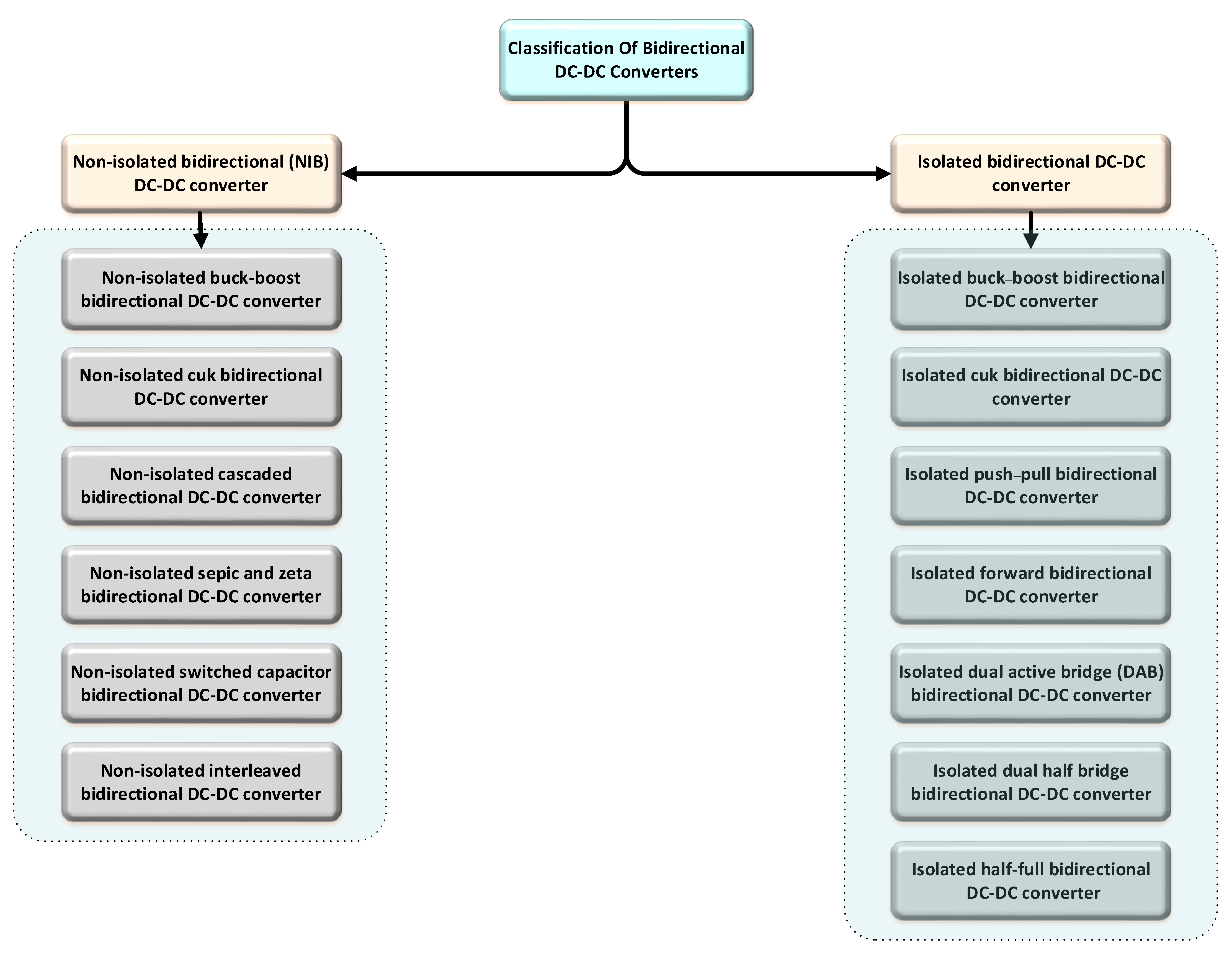
Galvanic isolation between outputs and inputs is used to classify a bidirectional converter [7]. Non-isolated bidirectional converters, or NIBDCs for short, do not provide magnetic isolation while transferring power. As a result of their simple design, little magnetic interference, and high weight owing to the transformer, they are advantageous. Because of these features, they are well-suited for applications where weight and size are vital considerations. DC voltage is transformed into an AC waveform using a high-frequency transformer, which is then rectified back to DC using an isolated topology. Isolated topologies have a more considerable voltage gain than non-isolated topologies. However, with these converters, reduced leakage inductance and transformer design are significant considerations. The topology of these converters will be examined in the following sub-sections. Figure 2 highlights the classification of bidirectional converters.

2.1. Non-Isolated Bidirectional (NIB) DC-to-DC Converter

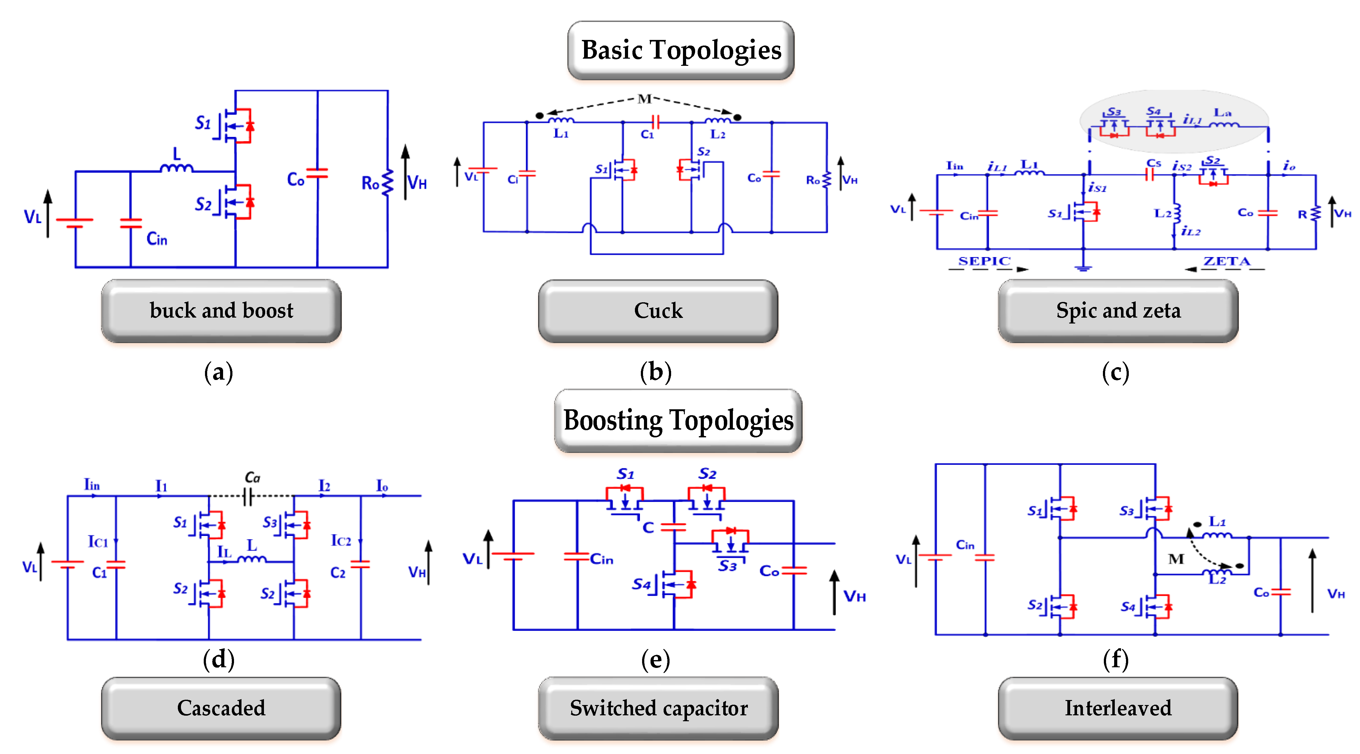
An NIBDC converter has no electrical isolation between the sources and loads. With the addition of an antiparallel diode to the switch, you can make a non-isolated bidirectional converter (assuming it is not already there). High-power converters like this one tend to be avoided because of this drawback. However, these converters are now more efficient and less expensive in low-power applications, where weight and controllability are more critical than power [8,9,10]. Figure 3 represents different topologies of non-isolated bidirectional converters, which are the buck and boost converter [11,12,13], cuk converter [14,15], cascaded converter [16,17,18,19,20,21], switched-capacitor converter [22,23,24], and interleaved converter [25,26,27,28,29,30]. In Table 1, the non-isolated bidirectional topology is compared for voltage gain ratio, switch count, passive components, circuit characteristics, and application.

2.2. Isolated Bidirectional (IB) DC-DC Converter

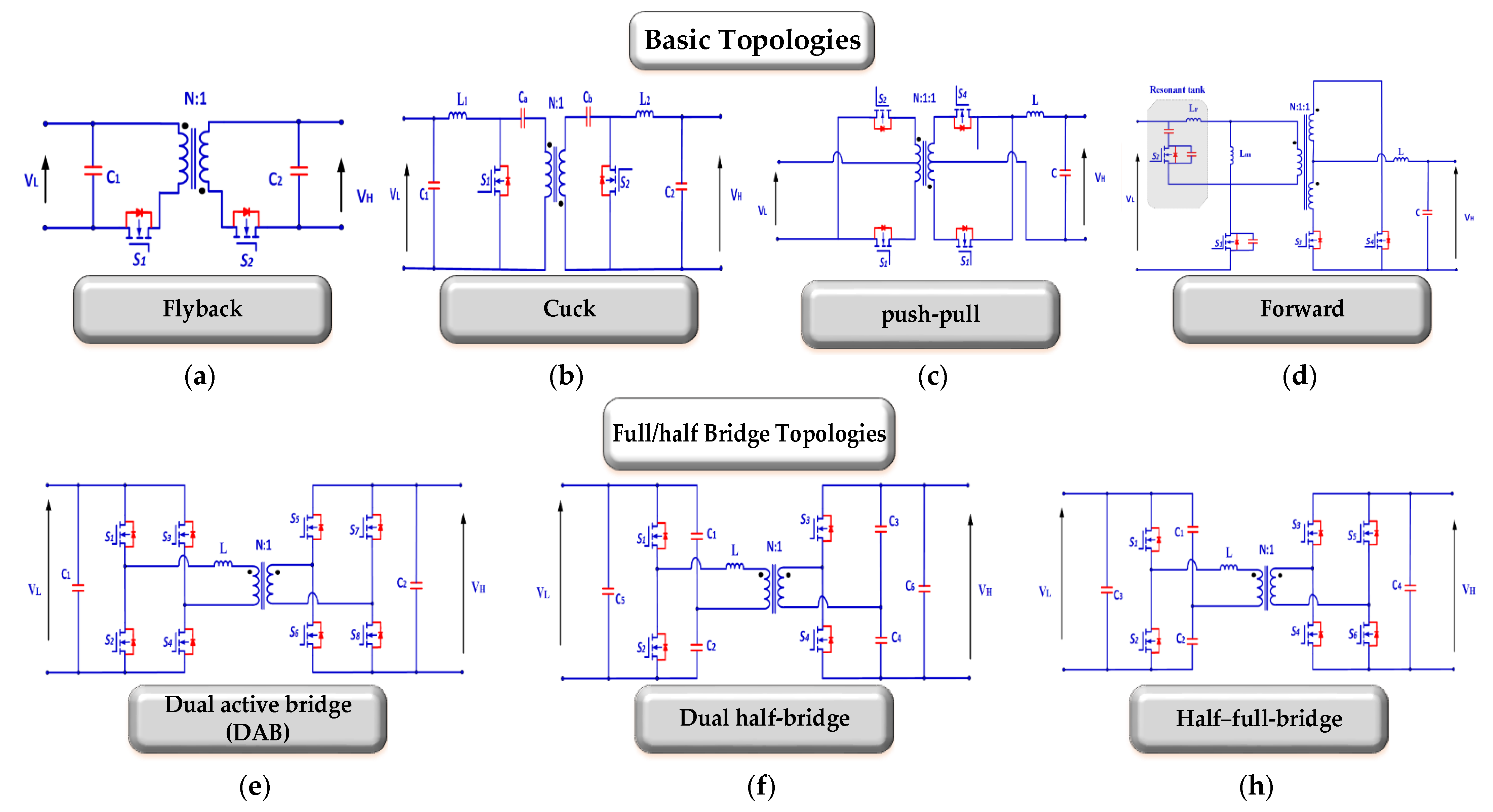
For galvanic isolation high frequency, there is a transformer in an isolated bidirectional DC-to-DC converter, making it bigger and heavier. Many applications need isolation to protect safety sources from overload, reduce noise, and match voltages between circumstances [40]. Furthermore, isolation provides other advantages, including the ability to implement multi-input/multi-output topologies and the ability to isolate sensitive loads from the input or output side. Switching converters come in two varieties. Stiff current characteristics are present at the terminals of current-type (or “current-fed”) structures’ inductors, which serve as a conventional boost converter at the input terminals. It features a capacitance with stiff voltage characteristics at its terminals that functions as a standard buck converter at its input terminals in a voltage-type construction. There are many operational differences among these converters. There are many uses for isolated bidirectional converters, but they are particularly well-suited to things like aero-planes, electric cars, and alternative energy sources. Many researchers are interested in dual active bridge phase shift converters because of their simple construction and bidirectional power flow capability. Renewable energy systems use them because of their unique characteristics. A bidirectional converter with a buck and boost function is known as a dual active bridge converter, and it was first presented in [41]. Many applications may benefit from its simple construction, control, isolation of converter ports, and bidirectional power flow [42,43,44]. Due to this wide variety of use cases, greater attention is paid to the converter’s features, such as the soft-switching range and efficiency [45,46,47,48]. A full bridge or current-fed full bridge performs DC-AC conversion; b) in the second stage, a high-frequency transformer raises the AC voltage and provides galvanic isolation. DAB’s general structure is shown in the following diagram, Figure 4. Depending on the desired application, AC-DC rectification may be completed using either an AC voltage-fed full bridge or an AC current-fed full bridge. ZVS/ZCS may be achieved using the resonant tank and transformer. Figure 5 demonstrates some isolated bidirectional converters, such as the buck–boost converter (Bidirectional Flyback) [43,49,50,51], cuk converter [33,52,53,54], push–pull converter [55], IB forward converter [49,56,57,58,59], dual half-bridge converter [45,60,61,62,63], and half–full-bridge converter [64]. Comparisons of isolated bidirectional topologies’ voltage gains, switch/inductor counts, circuit characteristics, and use cases are shown in Table 2.

3. Bidirectional Improvements towards Bidirectional Multiport Converters

Bidirectional DC-DC converters, essential for enabling power flow in both directions, are increasingly used in energy storage, UPSs, electric vehicles, and renewable energy systems. A 2019 study by reference [1] delved into their design and control, highlighting non-isolated and isolated types, each with various groupings, schematics, and summaries. It examined conventional control strategies, including PID, sliding mode, and digital controls. Isolated converters saw advancements with phase-shifting techniques for improved configurations and selection for specific applications.
JIAQI YUAN et al., in 2021 [76], provided a comprehensive review of bidirectional OBC technologies, focusing on designs, smart modes, and industry standards. It detailed promising topologies and discussed wideband technologies, thermal management, and system integration, including wireless charging.
Albert Bassa de Los Mozos and colleagues [77], in 2019, explored a three-port converter for EV charging from PV panels, considering various technical aspects to determine the most efficient and compact design.
Rafael et al.’s 2018 research [78] proposed a novel, bidirectional, multi-level EV battery charger, integrating AC-DC and DC-DC converters with a split DC-link for varied voltage levels to enhance smart grid integration.
Wang, H. et al. (2023) [79] introduced a technique leveraging a physics-informed network to pinpoint the maximum torque per ampere (Mtpa) and flux-weakening trajectories in electric drives, obviating the requirement for calibration.
Yang, X. et al. (2023) [80] developed a finite-time adaptive dynamic surface control strategy for dual-motor servo systems, aimed at mitigating backlash and dynamic uncertainties. Their study contributes to enhancing the synchronization and operational performance of these systems, providing critical insights for the advancement of control technologies in industrial environments.
Majid Hosseinpour et al., in 2020 [81], introduced a bidirectional multilevel inverter with fewer switches, suitable for medium voltage applications, and tested its performance and efficiency through simulation and experimentation.
Andrei Blinov’s 2018 study [82] presented a soft-switching bidirectional DC-DC converter, demonstrating its functionality and efficiency through experimental validation and highlighting its potential for low-voltage DC source integration into higher-voltage DC buses.
The advantages of multiport bidirectional DC-DC converters over traditional ones, as discussed in references [83,84,85], include their capability to integrate multiple energy sources and loads, offering enhanced power management, system efficiency, and reduced complexity and costs, which are vital for evolving energy systems and increased renewable energy integration.
A multiport bidirectional DC-DC converter is typically proposed as an alternative to a conventional bidirectional DC-DC converter due to its many valuable features and the many situations in which it is superior [83,86,87,88,89,90,91].
Lin et al. (2022) [92] investigate the stability of three-phase grid-connected inverters under weak grids with asymmetrical impedance, utilizing Ltp theory in the time domain. In another study [93], they enhance passivity in grid-connected inverters through improved synchronization units for weak grids.
Mohseni et al. (2018) [94] introduce a new high step-up multi-input multi-output DC-DC converter, enhancing power conversion efficiency. Dezhbord et al. (2022) [95] develop a high step-up three-port DC-DC converter with reduced voltage stress, aimed at improving hybrid energy systems.
Chen et al. (2022) [96] present a new technique for the subdomain method in predicting the electromagnetic performance of surface-mounted permanent magnet motors with shaped magnets and a quasi-regular polygon rotor core. Li et al. (2022) [97] introduce a fast and accurate calculation method for line breaking power flow based on Taylor Expansion.
Reliability and redundancy are enhanced with multiport converters. Managing multiple power sources and paths increases the system’s resilience to failures or disruptions in one or more energy sources. This reliability is invaluable in critical applications, such as healthcare facilities or data centers, where uninterrupted power supply is essential. Additionally, the redundancy provided by multiport converters ensures continuous operation, an essential requirement in many industrial and commercial settings [98,99].
Advanced control strategies are often incorporated into multiport converters, enabling more dynamic and responsive power management. These strategies are necessary for systems like microgrids, which operate independently and in conjunction with larger grids. The advanced control capabilities allow for real-time adjustments in power flow, optimizing the system’s performance under varying conditions. This level of control is significant in applications where energy demands fluctuate significantly, thus ensuring that the system remains efficient and stable [21,100,101].
The benefits of multiport bidirectional DC-DC converters that make them preferred include the following:
  • Multiport converters can handle multiple energy sources and loads simultaneously. This is particularly beneficial in systems like renewable energy, where solar, wind, and other energy sources might need to be integrated.
  • These converters offer more flexibility in managing power flow between different ports, which can lead to increased overall system efficiency. They can optimally distribute power based on the demand and availability of each source.
  • By integrating multiple functions into a single converter, the complexity and cost of the overall system can be reduced. This integration eliminates the need for multiple separate converters and the associated interconnections.
  • Multiport converters can provide higher reliability and redundancy. If one energy source fails, the system can continue using other sources without interruption.
  • These converters can implement advanced control strategies for power management, which are crucial in systems like microgrids and hybrid electric vehicles.
  • With the increasing use of distributed energy resources and the need for smart grid technologies, multiport converters align well with these modern requirements, offering better integration and control capabilities.

4. Multiport DC-DC Converters

Traditional approaches, which necessitate an extra converter for the energy storage system, are often considered inefficient. This requirement for an additional converter is seen as a substantial drawback. The multi-stage structure inherent in these methods can result in increased final costs, lower power density, and a larger overall system size [77]. To address these limitations, a multiport converter is employed in applications requiring multiple input energy sources, like fuel cells, wind turbines, and solar photovoltaic (PV) systems. This approach streamlines the integration of various energy sources into a single system, enhancing efficiency and reducing the complexity associated with conventional methods [102].
This type of converter, falling under the multi-input converter category, can supply the necessary power to the load using a single-stage method. Since these converters do not incorporate an energy storage system, they may face limitations in meeting the required power demands, significantly when the output power exceeds the input power. This constraint highlights the need to carefully consider power management in systems that rely solely on multi-input converters without energy storage backup [103].
Multiport DC/DC converters have a range of applications, including hybrid energy systems, fuel cells, and systems requiring an uninterrupted electricity supply. These converters are categorized into (a) isolated and (b) non-isolated.
Isolated converters separate the low- and high-voltage sides, allowing for high-voltage conversion to match different voltage levels while minimizing the risk of shock hazards by avoiding using semiconductors with high current/voltage ratings. This type typically employs high-frequency transformers. However, a significant drawback of isolated converters is their size and cost, primarily due to the substantial material requirements for the transformer core.
On the other hand, while differing in structure, non-isolated converters also play a crucial role in various applications, each type having its specific benefits and limitations [104,105]. In contrast, non-isolated converters have a less complex design and are utilized when galvanic isolation between the power source and the load is unnecessary.
This approach, particularly in non-isolated converters, can achieve high power density at a lower cost, primarily due to the reduced number of components required. While non-isolated converters efficiently match the input and output impedances of the source and load, they cannot achieve a high voltage conversion ratio. This constraint highlights a trade-off between the benefits of simplicity, component reduction, and the ability to handle large voltage conversions [106,107].
Many studies have been conducted on TPCs, but only a select handful have systematically investigated the process of TPC topology derivation or provided in-depth analyses of various TPC classes. In ref. [108], a generic topology is provided, demonstrating the combination of DC-link and magnetic coupling, from which a series of multiport bidirectional DC-DC converters are built. The converters derived from this straightforward process are highly integrated and inexpensive. Isolated TPCs are built with full-bridge or half-bridge converters; non-isolated TPCs cannot be generated this way. It follows that the general configuration lacks robust universality. Ref. [95] suggests a method for building TPCs using pulsing source cells (PSCs) and output filter cells derived from standard non-isolated DC/DC converters. This method is easy to understand, versatile, and regular. However, the resultant TPCs still have drawbacks, such as high switching costs, low power density, and inadequate power transfer.
In ref. [109], a family of non-isolated TPCs is built by a combination and optimization construction approach from dual-input and dual-output converters; these TPCs are instructive and valuable. Nonetheless, there is a lack of comprehensive knowledge about TPCs. Power flow diagrams are used in [110] to methodically obtain the construction approach of double-input single-output (DISO) DC/DC converters. Based on these diagrams, thirteen different configurations of DISO converters are provided, each consisting of two basic units; four converter configurations are appropriate for battery-connected applications. To obtain DISO converters, simple units are swapped out for those with two outputs.
Additionally, the efficiency of various configurations is computed and compared between theoretical estimates and experimental measurements. Because some parts of the basic units, like inductors, are not shared, the power density of these derived converters is low. In addition, other TPCs cannot be derived from these four configurations, including the TPCs shown in [111,112,113,114,115,116,117,118,119,120,121], which comprise three fundamental units. In ref. [26,99], converter designs are used to categorize, analyze, and compare isolated and non-isolated TPCs, providing a more thorough overview of TPCs. As a result, the findings offer promising directions for the further study of TPCs.

4.1. The Fundamental Principles of Operation for a Three-Port DC-DC Converter

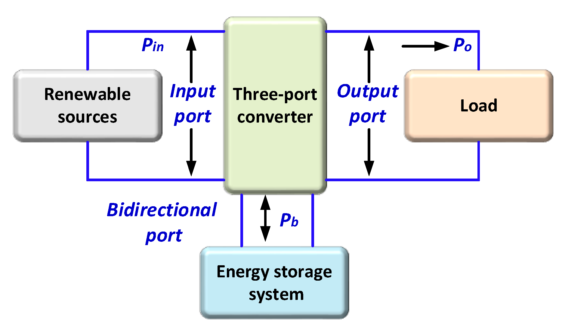
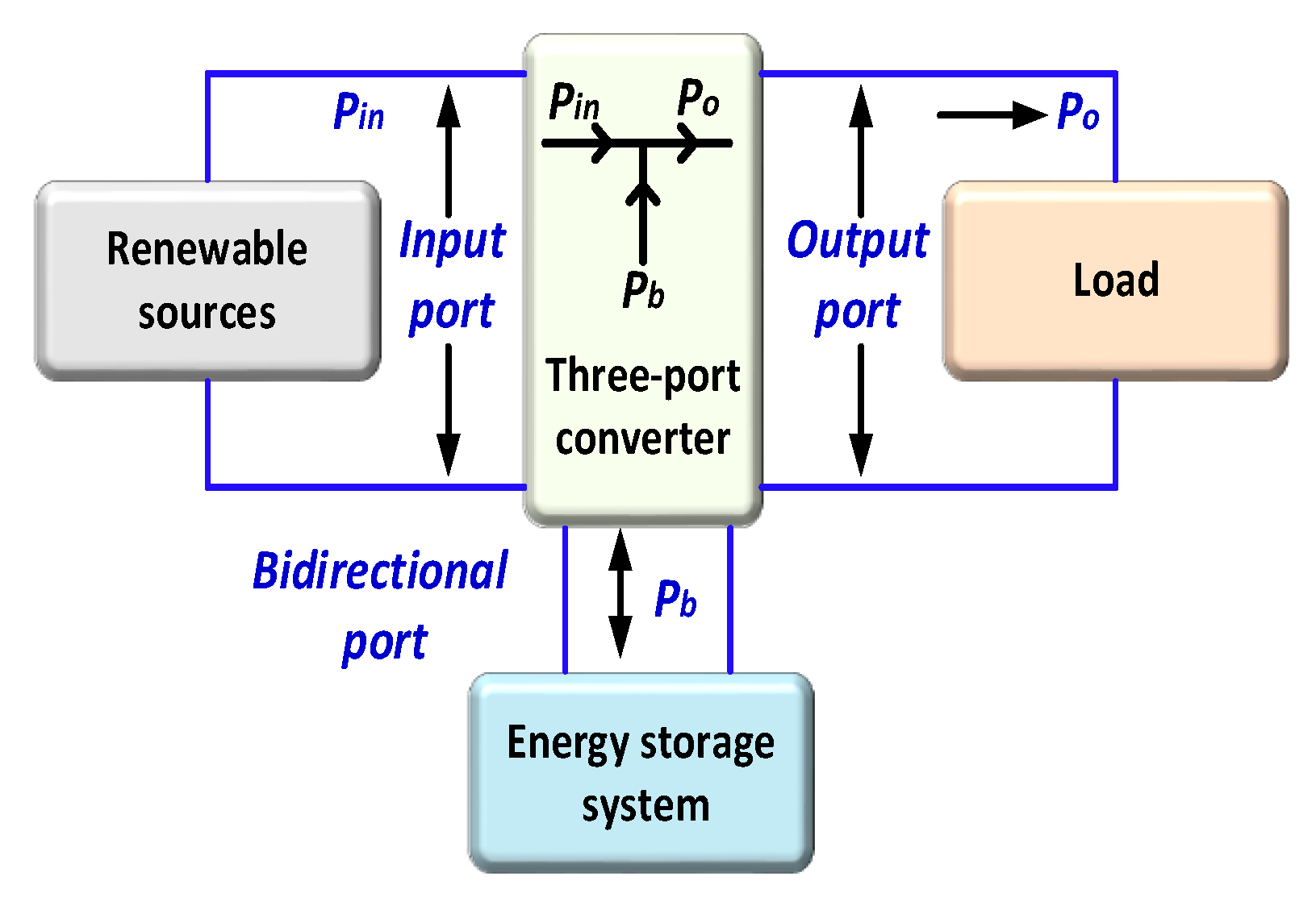
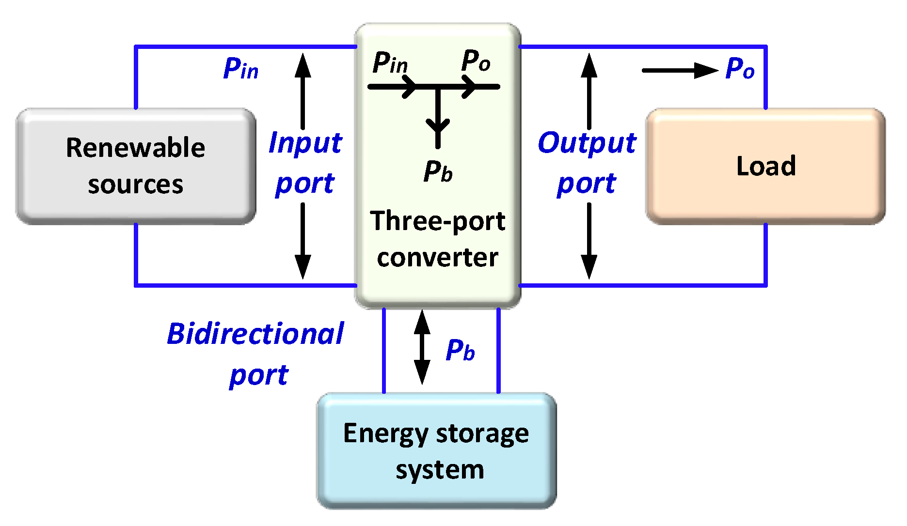
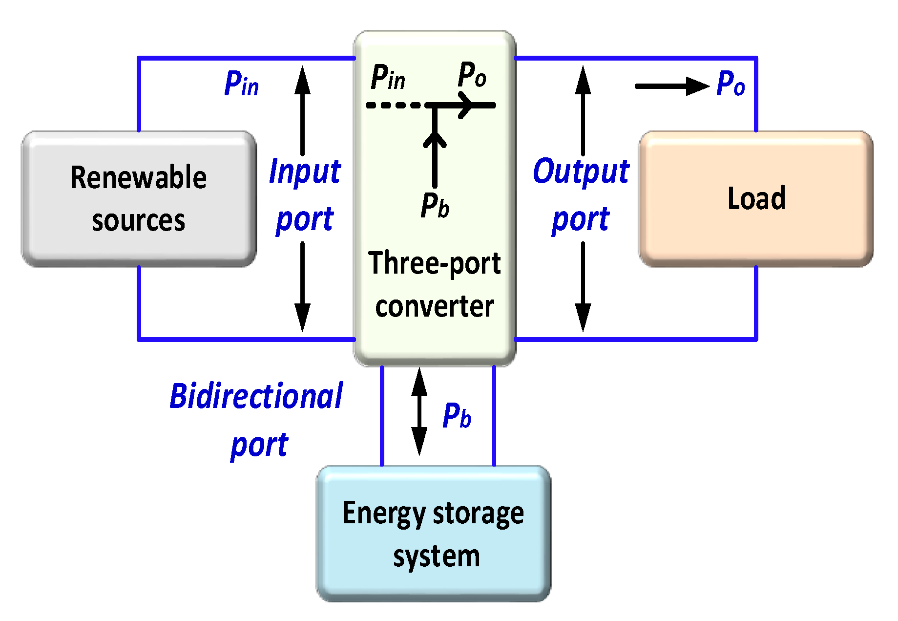
In order to combine multiple DC sources in a single component, a three-port DC-DC converter is utilized [108]. The configuration of the three-port DC-DC converter with three input sources is shown in Figure 6.
These three ports are connected to the three output DC sources as the following renewable energy source: the DC bidirectional port is connected to the battery, and the third port is connected to the wind energy source [109]. The powers among these three ports can be illustrated in the following relationship:
P o u t = P i n + P b
where P o u t represent the DC output power, P i n acts as the DC input power from the renewable energy source, and P b illustrates the DC input power from the battery [86]. Several types of three-port DC-DC converters are illustrated in the next section.

4.2. Non-Isolated Three-Port DC-DC Converters

Various non-isolated three-port DC-DC converters have been explored in the literature, each employing different control and modulation techniques. Some of these converters utilize a single inductor design, which helps maintain a smaller size and increases power density. Additionally, there are three-port DC-DC converters that incorporate coupled inductors. Coupled inductors are a strategic choice to enhance the voltage conversion ratio, thereby addressing the limitations typically associated with non-isolated converters in achieving high-voltage conversions. This diversity in design and functionality demonstrates the adaptability of three-port DC-DC converters to different application requirements.

4.2.1. Dual-Input–Single-Output DC-DC Converters (DISO)

This type of converter proposed double input and single output for high and low voltage. The buck–boost and the buck converter are combined in this converter, as shown in Figure 7. There are four major operational modes based on the availability of input voltage sources and the state of their respective switches’ conductivity ( S 1 and S 2 ). The low-voltage source ( V l o w ) is used to supply the base load, while a high-voltage source   V h i meets the needs of the supplementary load. The input voltage sources charge the inductor when their respective switches are ON. The diodes are reverse-biased when the switches are ON, and the diodes allow for the discharge of the inductor current when the switches are off [110]. Figure 7 presents the block diagram of the DISO mode.
The relationship between the input–output voltage can be delivered from the volt-second balance principle
V 0 = d 1 1 d 2 V h i + d 2 1 d 2 V l o w
where:
d 1 and d 2 : the duty ratio of switches S 1 and S 2 , respectively;
V 0 : the output voltage.
Passive lossless switching can be connected in the circuit to reduce the switching loss and increase overall efficiency [111].

4.2.2. Single-Input–Dual-Output DC-DC Converters (SIDO)

The SIDO is employed in many applications such as (mobile phones, digital cameras, hand smartphones, and MP3 players). Figure 8 shows a block diagram of this type. Various switches rapidly conduct inductor current to their output voltages in this method. The other technique obtains output energy from the inductor complementary terminals [112]. In the third approach, the switched nodes charge the capacitors. A family of SISO is delivered from the boost converter to step up or down applications. As a result, when the number of switches is reduced, the converter’s overall cost decreases. The major problems, such as high ripple and cross-regulation of output voltages, are solved using a SIDO buck converter [113].
The output voltages are controlled by adjusting the duty cycles, d 1   and d 2 , and the relationship between the input and output steady state is given by:
V 0,1 V i n = d 1 d 2 R 1 d 2 2 R 1 + ( 1 d 2 ) 2 R 2
V 0,2 V i n = d 1 ( 1 d 2 ) R 2 d 2 2 R 1 + ( 1 d 2 ) 2 R 2
The duty cycles are calculated as follows:
d 1 = I 0,1 I 0,1 + I 0,2 ,   I 0,1 + I 0,2 = I L
d 2 = V 0,1 [ d 2 2 R 1 + ( 1 d 2 ) 2 R 2 V i n d 2 R 1

4.2.3. Single-Input–Single-Output Mode (SISO)

The equivalent circuit of this mode is presented in Figure 9. In this type, one switch is ON, and the other switch is OFF. The battery supplies power to the load alone, while the converter acts as a traditional boost converter [114].
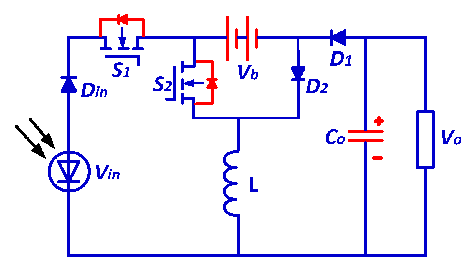
A non-isolated converter is proposed in [116,118,119] for solar PV applications that contain a single inductor, three switches, and three diodes, as illustrated in Figure 10. The suggested converter is built from a dual-input converter by the addition of a new power flow line, resulting in an additional control variable that can be implemented with any of the six standard DC-DC converters, such as the buck, boost, buck–boost, zeta, sepic, and cuk converters, and it is a part of the non-isolated three port DC-DC converter family [116]. Using appropriate control techniques, the power flow can be controlled between any two of the three ports. Its benefits are high power capacity, smaller size, and higher efficiency.
In [119], a traditional buck–boost converter consists of a general cell with a diode, switch, and battery storage, as shown in Figure 11, where the details of the analysis are provided in [120]. This general cell can be connected to any traditional converter to form a new three-port DC-DC converter, which is the advantage of this work because of its simple computation and small size [119].
In [121], a novel non-isolated three-port DC-DC converter was proposed by connecting a traditional buck converter with a boost converter between these two converters, as an additional switch, as illustrated in Figure 12. The benefit of this circuit is the ease of operation and simplicity of control [121].
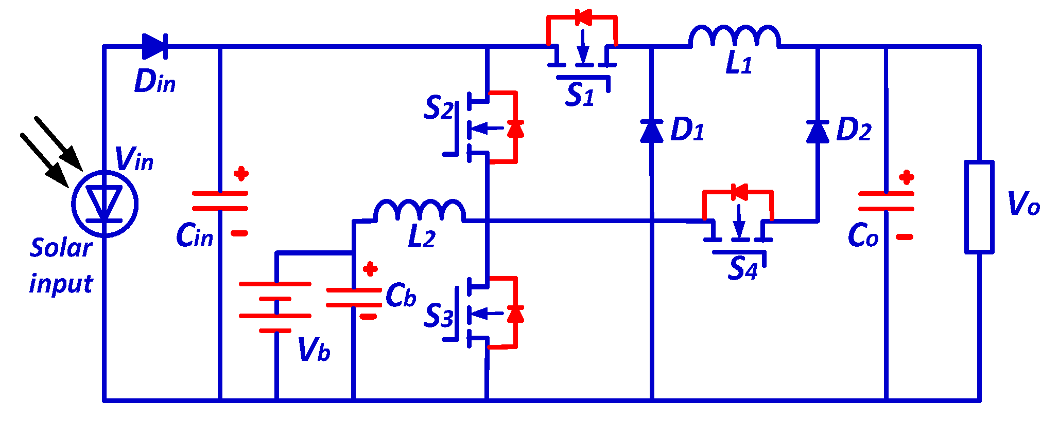
A three-port DC-DC converter is proposed in another work by connecting a bidirectional power flow path of the traditional converter with two unidirectional power flow paths, as shown in Figure 13 [122]. By applying a multi-regulator competition control technique used to track a maximum power point tracking (MPPT), which is used to control the fluctuation in the PV system with the environment and weather, the experimental results explain in detail the operation of this converter [122]. The advantage of this converter is higher reliability and higher power capacity.

4.3. Partly Isolated Three-Port DC-DC Converters

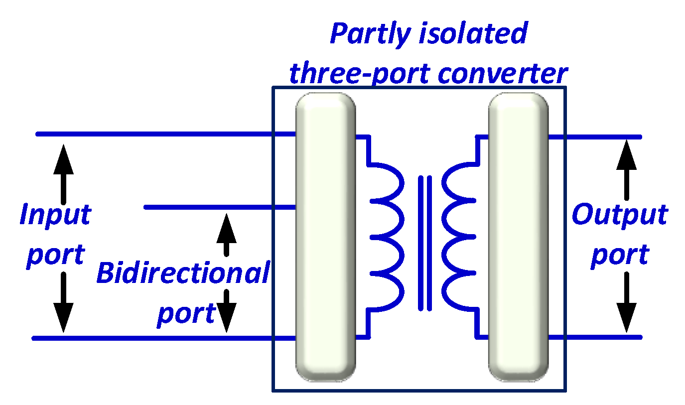
Partly isolated three-port DC-DC converters mean that one or two ports in the circuit are isolated [109]. There are usually two types including the following: the first contains two directly connected ports, while the third is connected with galvanic isolation. The input to this third port is the output of these two ports. Then, they are connected to the isolated output port, as illustrated in Figure 14 [123].
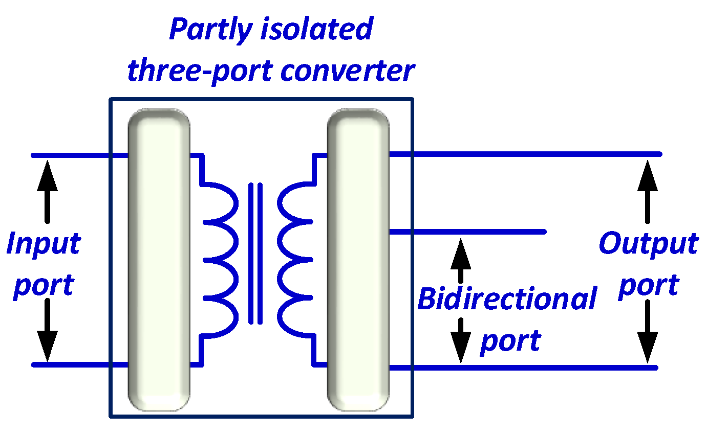
The second type connected the two output ports directly without galvanic isolation, and then a high-frequency transformer was connected to the input port, as shown in Figure 15 [123].
Based on a half-bridge converter, the three-port DC-DC converter is proposed in [104,124], as briefly in Figure 16.
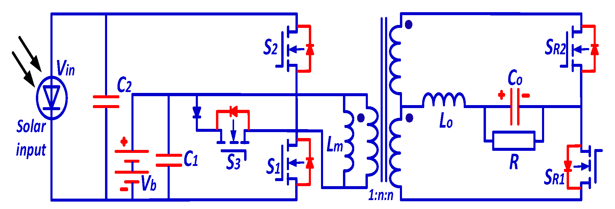
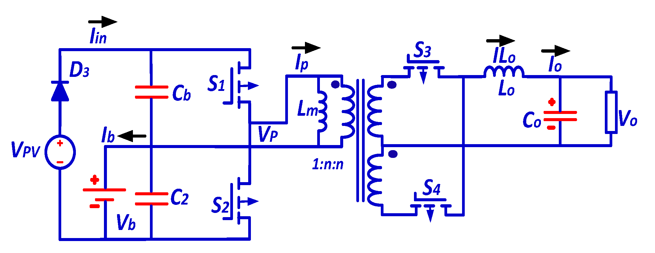
The traditional half-bridge converter with a switch and a diode is connected to the transformer’s primary side and uses two switches to replace the diode in the output port. All the switches on the primary side can operate under zero voltage switches to a wide range [124]. The duty cycle controls the power flow among these three ports by controlling the two primary-side switches. The application of this converter is briefly explained in [125,126,127]. The advantage of this circuit is strict load control and a wide range of conduction [124,125,126,127]. Based on a half-bridge converter, a novel partly isolated three-port DC-DC converter has been proposed [128,129]. This converter is utilized for the renewable power system application, as shown in Figure 17 [129].
The two switches at the transformer’s secondary side for synchronous regulation of the voltage of the three ports can be regulated independently. The advantages of this converter are high integration, simple structure, and fewer device numbers [130].

4.4. Fully Isolated Three-Port DC-DC Converters

Isolated three-port DC-DC converters employ a high-frequency transformer with multiple windings, facilitating power transmission between the three ports. The essential advantage of this type of converter is its high degree of galvanic isolation. Each of the three outputs in this converter configuration has its dedicated component. In practical applications, most isolated converters typically rely on either full-bridge or half-bridge converters, or a combination of both, to manage the energy transition [131].

4.4.1. Multi-Input Total Bridge Converter (FBC)

A full-bridge DC-DC converter with a multi-winding transformer is shown in Figure 18. This converter includes two input sources of varying amplitudes and the magnetic flux produced in the transformer core. It has two power supplies, three winding transformers, and a single output port. Increasing the number of input sources is possible while keeping the output port and coupling transformer the same [132]. The voltage across the inductor is given as follows:
V L 1 = V S 1 n 1 n 3 V 0 θ 1 T S 2 + V S 1 ( 1 θ 1 ) T S 2 = 0
where:
  • n 1 , n 3 : The primary and secondary turns of the transformer;
  • V S 1 : The first input voltage supply; V L 1 : the voltage across the inductor;
  • θ 1 : The percentage of phase shift for Input Source 1; V 0 : The output voltage;
  • T S : The switching time.
  • The relationship between the first input source and output voltage and the second input source and output voltage can be given as follows:
V S 1 = n 1 n 3 θ 1 V 0
V S 2 = n 2 n 3 θ 2 V 0
where θ 2 : the percentage of phase shift for Input Source 2.

4.4.2. Multi-Input Half-Bridge DC-DC Converters (HBCs)

The half-bridge converter (HBC) is recognized as one of the most straightforward isolating topologies. The primary switches are usually operated in an alternating or complementary sequence in this setup. The input capacitors are often treated as voltage sources in a half-bridge converter. This converter is called a “symmetrical half bridge” because it utilizes two similar switches controlled by identical signals that are phase-shifted by 180 degrees. Conversely, an asymmetrical half-bridge employs driving signals that are not identical. Figure 19 illustrates the equivalent circuit of a three-port half bridge [60].
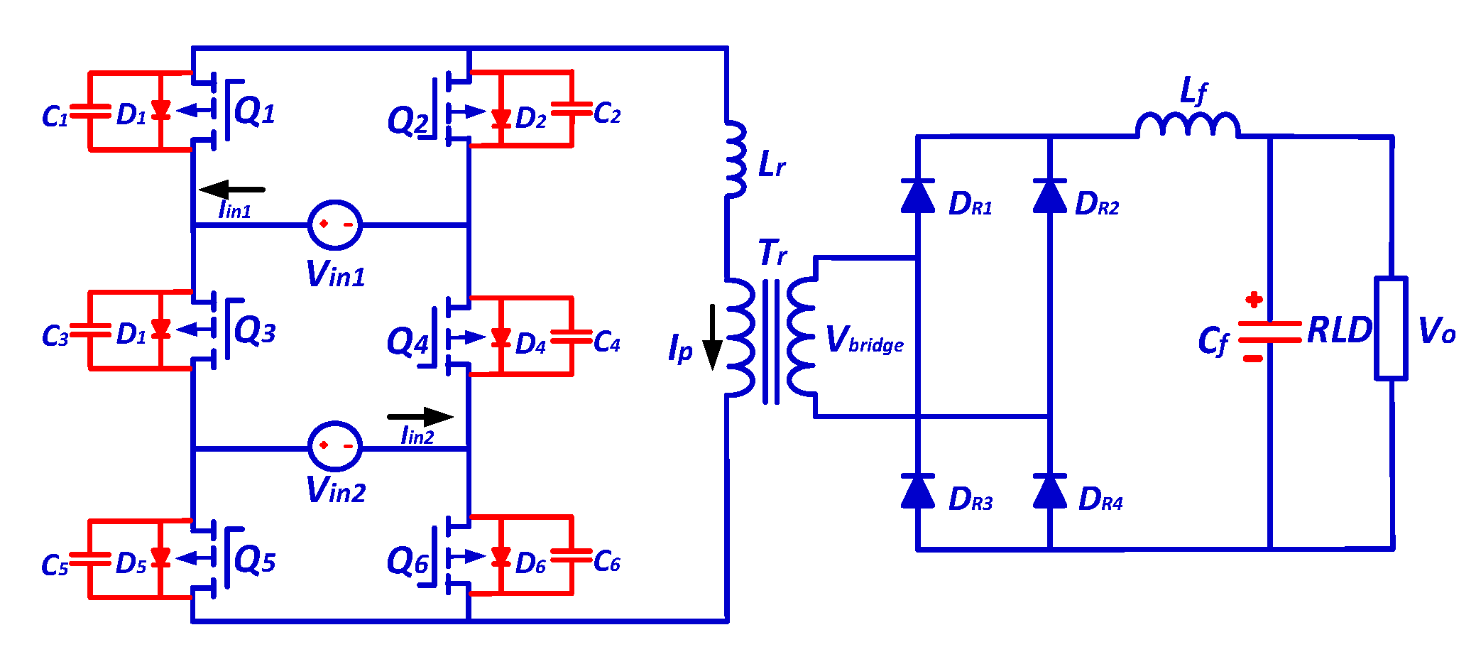
In ref. [131], as proposed with the three-port converter topology, the battery charger and DC-DC converter are combined in a single device. One port of the three-port converter is inactive, while the other two are active. A virtual isolation system is presented to prevent electricity from flowing into an idling port. The proposed converter is shown in Figure 20.
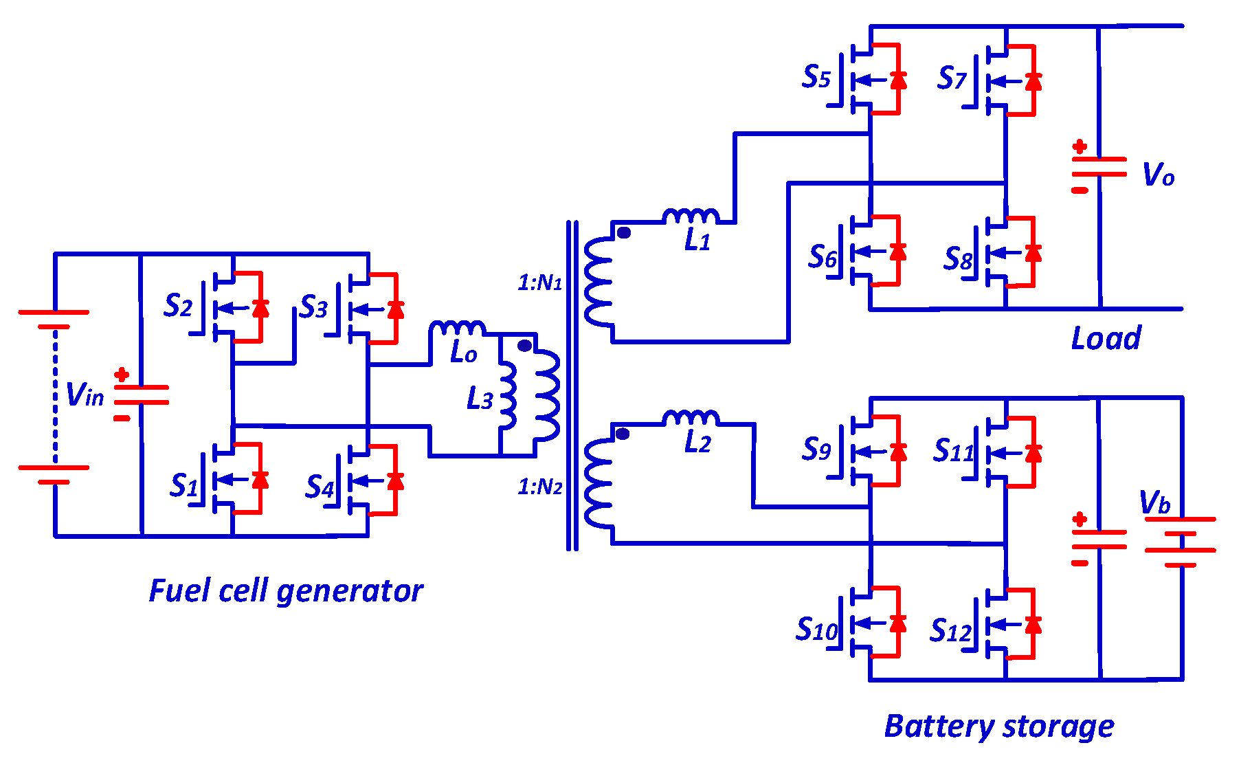
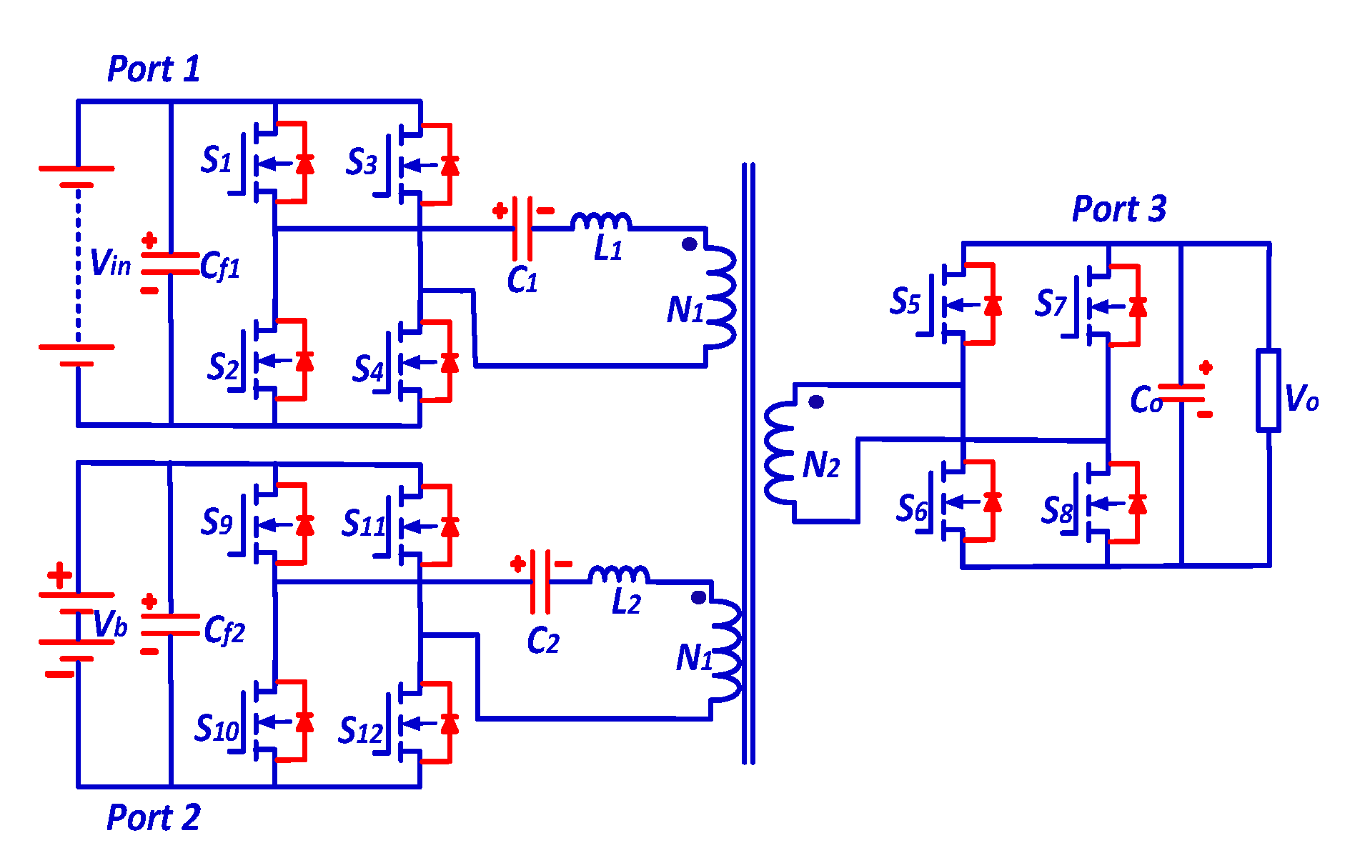
Reference [135] proposes a three-port converter design that includes three active full bridges, two series-resonant tanks, and a three-winding transformer, all integrated into a single power conversion stage. This design employs a high-frequency link to regulate the power flow among batteries, load, and a renewable energy source like a fuel cell. The converter can complete bidirectional power transfers between the battery and the load. This proposed converter design is showcased in Figure 21.
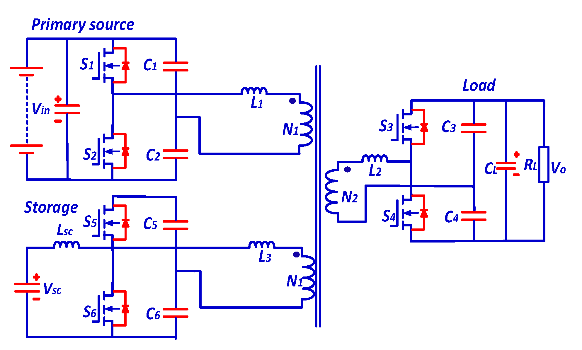
In reference [136], a new three-port DC/DC converter design is introduced, featuring three half-bridge structures as a replacement for the full-bridge structures typically used in converters, as depicted in Figure 22. Additionally, this converter incorporates a boost half-bridge circuit as one of its three half-bridge components. This particular circuit facilitates the energy storage system’s bidirectional charging and discharging functions.
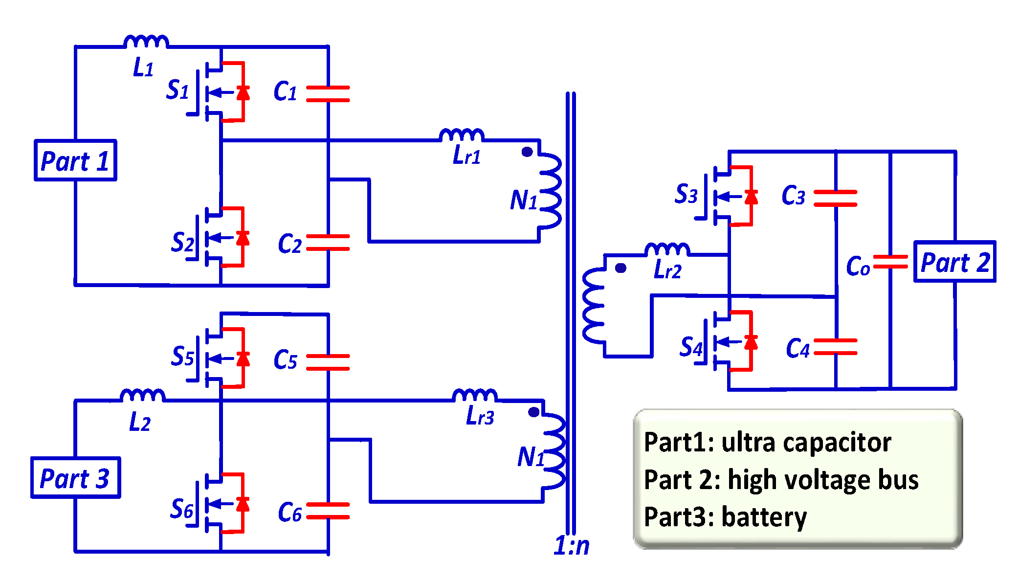
Ref. [137] investigated the use of an inductor in the input port to minimize ripples in the input current, as shown in Figure 23.

4.4.3. Comparison of Three-Port Converters

The primary objective of these three-port DC-DC converter architectures is to mitigate the intermittent characteristics of renewable energy by utilizing energy storage and a single DC-DC converter with dual inputs. Over the past ten years, numerous designs for three-port DC-DC converters have emerged, each with unique advantages and challenges. This study provides a comparative analysis, focusing on factors such as the number of components, cost, complexity, and reliability of these converters. This comparison aims to facilitate the selection of appropriate three-port converters for practical applications, as detailed in Table 3 [138].
Regarding the cost of control circuits, non-isolated three-port converters are generally more affordable. They require fewer power-switching devices and have a lower total component count than their partly isolated and fully isolated counterparts. However, the cost of fully isolated and partially isolated three-port converters can increase due to the necessity of a high-frequency transformer. Non-isolated converters employing coupled-inductor topologies are more expensive than other converter types.
System complexity is primarily determined by the number of components and controllers, with complexity rising as these increase. The design of non-isolated three-port converters is the simplest as they do not include transformers and have fewer components than the fully isolated and partially isolated versions. The fully isolated converter is more complex, incorporating three winding transformers and accommodating unidirectional and bidirectional ports.
Reliability is a crucial metric for evaluating the performance of converters. Generally, reliability tends to diminish as the operational time increases. At the component level, reliability decreases with an increased number of switches used in the converter. Consequently, non-isolated and partially isolated converters often exhibit higher reliability than fully isolated converters.
Several factors influence efficiency, including the topological structure, rated power, switching frequency, and selection of components. Systems with fewer power conversion stages typically show improved efficiency. Thus, the topological structure significantly affects the system’s efficiency. Since in many designs, a large portion of the power is transmitted directly to the load port along the primary path, reducing the number of power conversion stages is possible, further enhancing efficiency.
Based on the most recent research in this area, a comparative analysis of prior studies was conducted to aid in choosing the appropriate type of DC/DC converter for renewable energy applications. The key findings and insights from these previous studies are conveniently summarized in Table 4.

5. Proposed Three-Port DC-DC Converter

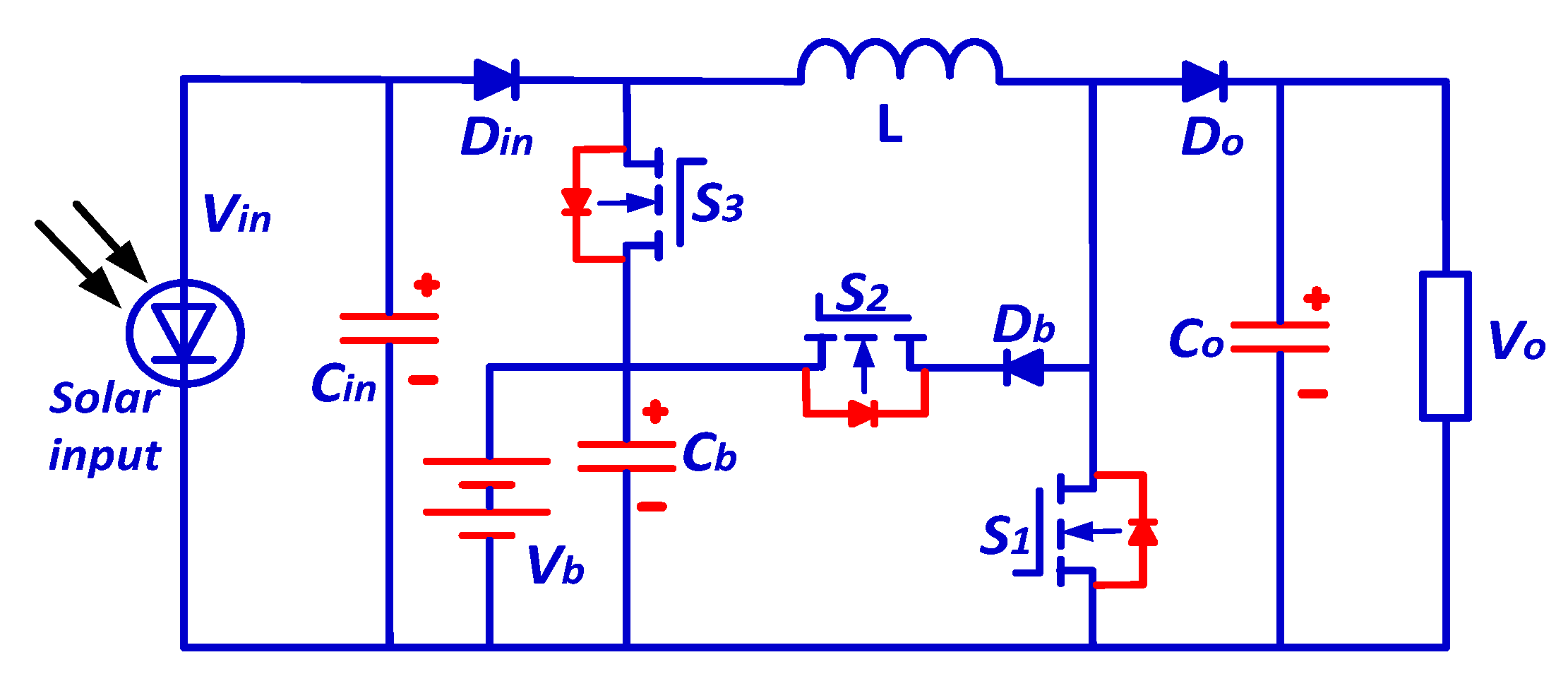
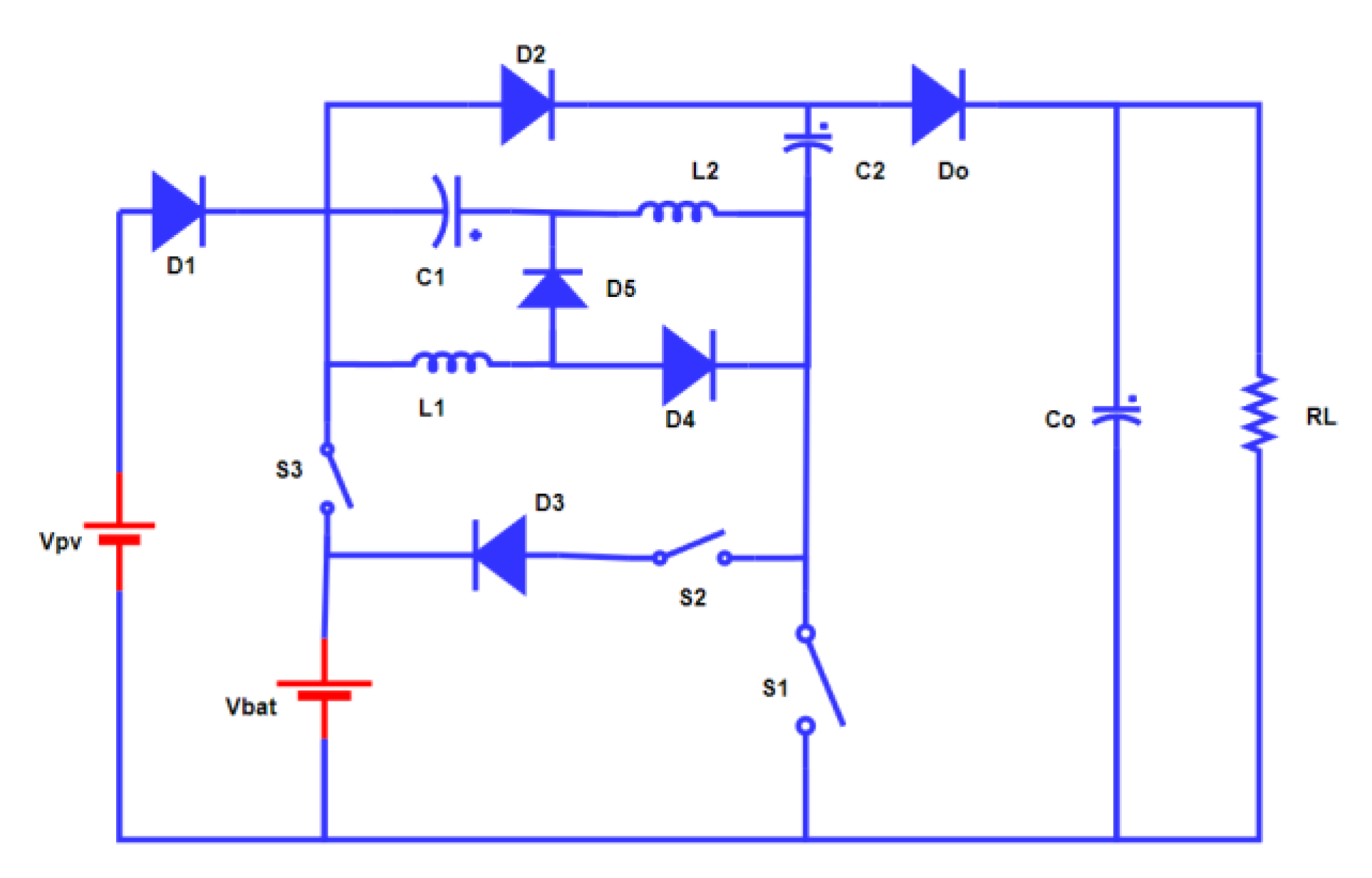
The proposed three-port dual-input bidirectional DC-DC converter is well suited for standalone renewable energy systems that incorporate a battery pack for consistent energy supply and require efficient power flow management, as shown in Figure 24. The converter’s design includes three switches, six diodes, two inductors, and three capacitors, enabling it to handle various operational scenarios, particularly in photovoltaic systems where the energy input is subject to climatic variations. The converter operates in two main phases as follows: Phase I, which manages power from both the PV source and the battery (with the battery discharging), and Phase II, where it directs power from the PV to both the battery and the load. Each phase encompasses three specific operational modes, making for a total of six, to ensure a steady and regulated output voltage across different weather conditions.
In Phase I, the converter’s modes adjust to changes in the relative voltages of the PV and the battery to optimize power flow to the load. For instance, when the battery voltage exceeds the PV voltage, sure diodes switch off to direct power flow appropriately, and similarly, when the PV voltage becomes dominant, the configuration changes to leverage this source. Phase II’s modes are designed to optimize the charging of the battery while also supplying power to the load, with specific switches and diodes activating or deactivating to manage the dual outputs efficiently.
The converter’s operational efficiency and adaptability are further supported by detailed voltage and current equations for each mode, following principles such as Kirchhoff’s Voltage Law and the volt-second balance law. These equations help understand the dynamics of power flow through the converter and are crucial for designing a control strategy that ensures optimal performance under varying conditions. The converter’s design, characterized by its specific combinations of active and passive components and operational modes, show cases a sophisticated solution for managing power in standalone renewable energy systems, ensuring reliability and efficiency in energy conversion and supply.
The mathematical equations of the proposed converter depend on two distinct phases to conclude the proposed converter. In Phase I, the converter functions with two inputs including the PV (VPV) and the battery (Vb), with the battery in a discharging state. Phase II features the converter operating with dual outputs, where the PV source supplies power to both the battery and the load. In each phase, the converter operates in three modes as follows: 1, 2, and 3 for Phase I and 4, 5, and 6 for Phase II.
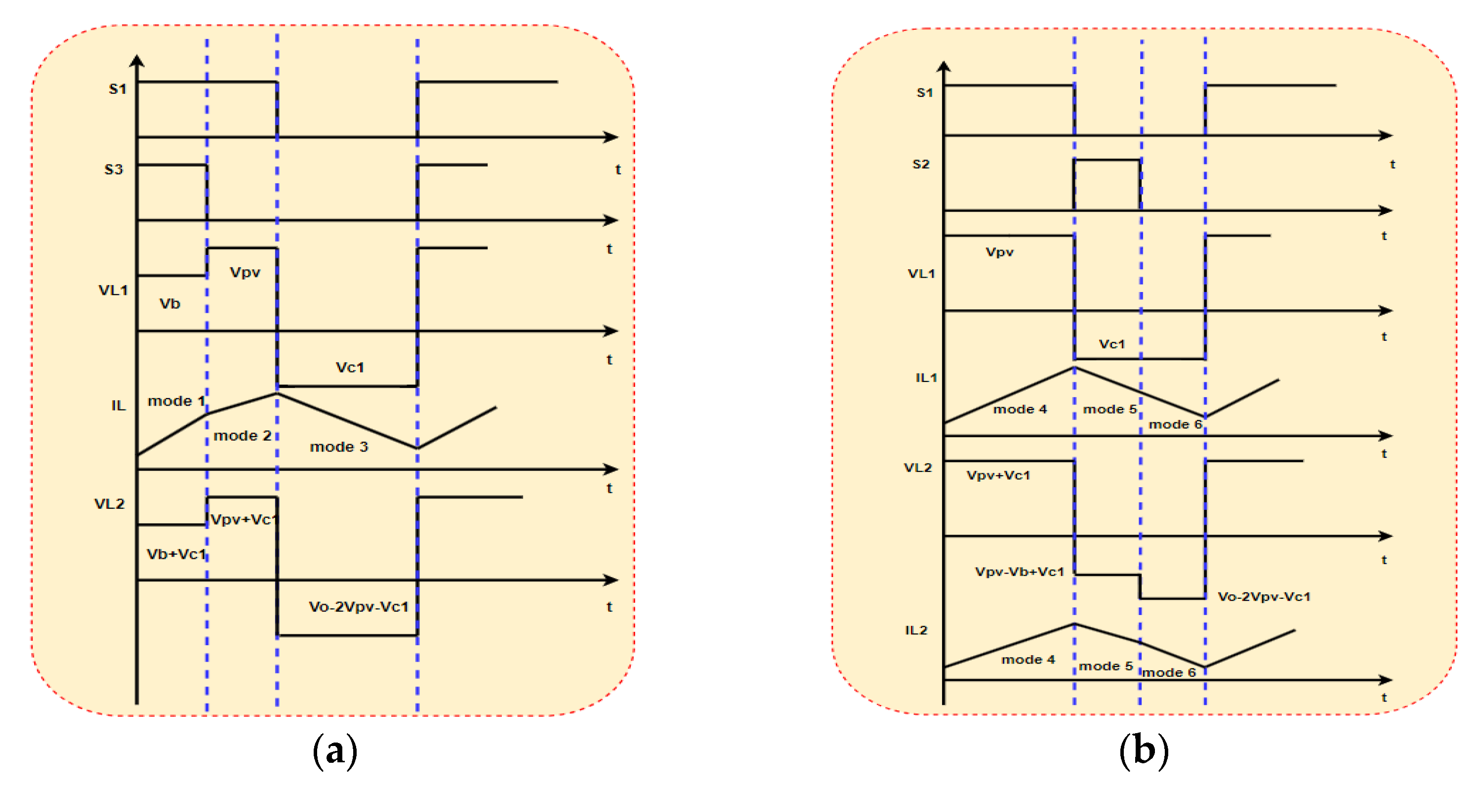
The six operational states of the converter are comprehensively discussed in this section, as depicted in Figure 25a–c and Figure 26a–c, respectively. The components of the converter include switches S1, S2, and S3, diodes D1, D2, D3, D4, and Do, inductors L1 and L2, and capacitors C1, C2, and Co.

5.1. Dual Input

During Phase I, the VPV and Vb sources supply power to the load. In this phase, switches S1 and S3 are sequentially activated and deactivated, while switch S2 remains deactivated, as depicted in Figure 27a.

5.1.1. Mode 1

In this scenario, both switches S1 and S3 remain in the ON state. Diodes D1, D3, and D5 are OFF if the battery voltage exceeds the PV voltage, as depicted in Figure 25a. During this mode, the capacitors and the inductor are charging. The capacitors are in the process of charging and, simultaneously, the capacitor CO discharges to the load. By applying Kirchhoff’s Voltage Law (KVL), the voltage across the inductors and capacitors can be described as:
V L 1 = V b V L 2 = V b + V C 1 V C 2 = V b

5.1.2. Mode 2

In this situation, switch S1 remains closed while S3 is open, as Figure 25b depicts. Diode D1 enters a forward-biased state because the battery voltage Vb is no longer more significant than the PV voltage VPV, thereby removing the reverse bias across diode D1. Diodes D2 and D4 continue to be in a forward-biased state. Capacitors C and inductors L keep charge throughout this mode, but the PV source powers them this time. Diode Do, connected to the output filter, remains OFF. The capacitors maintain their state as in the previous mode. The voltage across the inductors and capacitors can be described as:
V L 1 = V p v V L 2 = V p v + V C 1 V C 2 = V p v

5.1.3. Mode 3

In this state, switches S1, S2, and S3 are non-conductive, as Figure 25c shows. Diodes D1 and D5 are ON, enabling the PV voltage (VPV) to power the load. All remaining diodes, however, are in the OFF state. Specifically, diode Do is connected to the output filter. The photovoltaic (PV) source supplies power to the system, while the capacitors and inductors discharge to increase the output voltage. At the same time, capacitor CO charges and discharges to the load. The voltage across the inductors and capacitors can be characterized as:
V L 1 = V C 1
V p v + V C 1 V L 2 + V C 2 V O = 0
V L 2 = 2 V p v + V C 1 V O
The equations of the modes above can be expressed as a result of applying the volt-second balance law at a steady state to the inductor equations:
V L 1 T O N = V L 1 T O F F
where T O N = D 1 T and T O F F = ( 1 D 1 ) T or T O N = D 3 T and T O F F = 1 D 3 T .
V C 1 = D 3 V b 1 D 3   o r   V C 1 = D 1 V p v 1 D 1
V L 2 T O N = V L 2 T O F F
V b + V C 1 D 3 T + V p v + V C 1 ( D 1 D 3 ) T = ( V O 2 V p v V C 1 ) ( 1 D 1 ) T
The output voltage is determined by simplifying Equation (18) and substituting Equation (16):
V O = V p v D 1 D 1 2 D 3 + 2 ( 1 D 1 ) 2 + V b D 3 1 D 1 1 D 3
The output current ( I o ) equals ( I o = V o R ), and by substituting Equation (19), and it can be expressed as:
I o = V p v D 1 D 1 2 D 3 + 2 ( 1 D 1 ) 2 + V b D 3 1 D 1 1 D 3 1 R

5.2. Dual Output

During Phase II, the power is supplied to Vb, and the load comes from the input source VPV. Switch S3 continues to be OFF throughout this phase, while switches S1 and S2 are subject to varying degrees of conduction.

5.2.1. Mode 4

Switch S1 stays in the ON state in this scenario. Diode D1 becomes reverse-biased if the storage element (SE) voltage exceeds the PV source voltage. During this mode, the capacitors and the inductors are charged. Diodes D2 and D4 remain in a forward-biased state, while diode Do, connected to the output filter, remains in the OFF state, as shown in Figure 26a. Energy is stored in capacitors and inductors, and capacitor CO discharges to the load. Figure 27b illustrates different modes of analysis and the waveforms of the proposed topology. By applying Kirchhoff’s Voltage Law (KVL), the voltage across the inductors and capacitors can be described as:
V L 1 = V P V V L 2 = V p v + V C 1 V C 2 = V p v

5.2.2. Mode 5

In this mode, distinct from Phase I, switch S2 remains in the ON state, as shown in Figure 27b. The battery charges in this mode, with the PV source supplying power to both the battery and the load, marking it as a dual output mode, as shown in Figure 26b. Switches S1 and S3 are in an open condition. Diode D1 is in a forward-biased state as the battery voltage Vb is no longer higher than the PV voltage VPV, effectively removing the reverse bias across diode D1. Diodes D2 and D4 are non-conducting. During this mode, the inductors and capacitors continue to charge, but the PV source powers them this time. Diode Do, connected to the output filter, conducts as the reverse bias across it is removed, allowing capacitor Co to transfer energy toward the load.
V L 1 = V C 1
V L 2 = V p v + V C 1 V b

5.2.3. Mode 6

Switch S1 is not conducting in this particular segment, and S2 and S3 remain OFF, as shown in Figure 26c. Diode D1 remains forward-biased, with the PV voltage (VPV) supplying power to the load. Diodes D2 and D4 are in the OFF state. The capacitors and the inductors continue to discharge during this mode, with the power supplied by the PV source. Diode Do, connected to the output filter, remains conducting. The voltage across the inductors and capacitors can be described as:
V L 1 = V C 1
V p v + V C 1 V L 2 + V C 2 V O = 0 , then:
V L 2 = 2 V p v + V C 1 V O
The equations of the modes above can be expressed as a result of applying the volt-second balance law at a steady state to the inductor equations:
V L 1 T O N = V L 1 T O F F
where T O N = D 1 T and T O F F = ( 1 D 1 D 2 ) T .
V C 1 = D 1 V p v 1 D 1 D 2
V L 2 T O N = V L 2 T O F F
V p v + V C 1 D 1 T + V p v + V C 1 V b D 2 T                                                                                                       = ( V O 2 V p v V C 1 ) ( 1 D 1 D 2 ) T
The output voltage is determined by simplifying Equation (29) and substituting Equation (27):
V O = V p v 2 D 2 2 + 2 D 1 D 2 2 D 1 3 D 2 + 2 ( 1 D 1 D 2 ) 2 V b D 2 1 D 1 D 2
The output current ( I o ) equals ( I o = V o R ), and substituting Equation (30), and it can be expressed as:
I o = V p v 2 D 2 2 + 2 D 1 D 2 2 D 1 3 D 2 + 2 ( 1 D 1 D 2 ) 2 V b D 2 1 D 1 D 2 1 R
Reducing current and voltage stress in a proposed converter significantly impacts the reduction in power loss. By minimizing the current flowing through components during both the ON and OFF periods, as detailed in the equations for current stress, the I2R losses, which are proportional to the square of the current through resistive components, are substantially decreased. Similarly, reducing voltage stress, as outlined in the voltage stress equations, decreases the electrical stress on components, leading to lower leakage currents and capacitive losses, which are voltage functions. Lowering these stresses enhances the converter’s efficiency by reducing power dissipation and potentially extends the components’ lifespan by operating them within more favorable conditions. This combined effect produces a more efficient, reliable, and durable power conversion system. In the below section, current stress and voltage stress equations are presented.

5.3. Current Stress Equations

Equations (32) and (33) describe the charge dynamics of the output capacitor CO during the switching cycle. Co+ represents the charge accumulated during the ON time (when the switch is closed), and Co- represents the charge during the OFF time (when the switch is open). The net charge over a cycle should balance to maintain steady-state conditions, implying that the charge gained during the ON time equals the charge lost during the OFF time.
Equation (34) gives the current through the output capacitor Co during the OFF period, denoted as ICo− off. This equation assumes that the net charge change over one cycle is zero, leading to a relationship between the duty cycles (D1 and D3) and the output current Io.
Equation (35) is a variation of (34), expressing ICo− off in terms of the output voltage Vo and load resistance R, assuming Ohm’s law, where Io = Vo/R.
Equations (36) to (38) describe the current through diode Do during its OFF period, denoted as IDo− off. This current is the sum of the capacitor’s OFF and output current, reflecting the diode’s role in directing the current flow when the switch is open.
Equation (39) establishes that the currents through the inductor L2 and capacitor C2 are equal to IDo− off during the OFF period, indicating these components discharge their stored energy to the output and load.
Equation (40) focuses on the current through capacitor C1 during the ON period, derived from the charge balance over a switching cycle. It shows how the duty cycle affects the charging current of C1.
Equation (41) states that the current through capacitor C1 during the OFF period is the difference between the currents through inductors L2 and L1, reflecting energy redistribution in the circuit.
The output capacitor Co is discharged during the ON time and charged again during the OFF period. Therefore, at steady state, the charge across Co at each switching cycle is:
Q C O + = I o D 1 D 3 T
Q C o = I C o o f f ( 1 D 1 ) T
During each cycle of the switching process, Q C O + = Q C O , and as a result, the current that flows through a capacitor during its off period is determined by an ideal output capacitor (CO).
I C O o f f = D 1 D 3 ( 1 D 1 ) I o
I C O o f f = D 1 D 3 ( 1 D 1 ) V o R
The current through a diode, denoted by Do, during the period in which it is not conducting, is:
I D o o f f = I C o o f f + I o
I D o o f f = D 1 D 3 ( 1 D 1 ) I o + I o
I D o o f f = ( 1 D 3 ) ( 1 D 1 ) I o
Also, the current of inductors and capacitors ( L 2 , C 2 ) during switching are OFF, and they are connected in series to discharge their stored energy to the output capacitor (CO) and the load through the output diode ( D o ) . As a consequence:
I L 2 = I C 2 = I D o o f f = ( 1 D 3 ) ( 1 D 1 ) I o
During the ON and OFF periods, capacitor C1’s charge increases and decreases, respectively. In each switching cycle, Q C 1 + = Q C 1 , and as a result, the capacitor’s current during the on period is:
Q C 1 + = Q C 1
I C 1 o n = ( 1 D 1 ) D 1 D 3 × ( 1 D 3 ) ( 1 D 1 ) I o = ( 1 D 3 ) I o D 1 D 3
I C 1 o f f = I L 2 I L 1

5.4. Voltage Stress Equations

Equations (42)–(46) relate to the voltage stresses across various diodes (Do, D2, and D1) during different operational phases. These equations are derived from Kirchhoff’s Voltage Law (KVL), ensuring that the sum of voltages around a closed loop is zero. They show how the voltages across the diodes are influenced by the output voltage Vo, the photovoltaic voltage Vpv, and the battery voltage Vb.
Equations (47) and (48) describe the voltage stress across diode D5 during the ON-switch phase, considering the voltages of the photovoltaic source, capacitor C1, and the diode itself.
Equations (49)–(51) focus on the voltage stresses across the MOSFET switches (S1, S2, and S3) during the OFF-switch phase, applying KVL to determine the relationships between the switch voltages, the photovoltaic source, and the battery.
Equation (52) describes the voltage stress across diode D4 during the OFF-switch phase, considering inductor VL1, photovoltaic Vpv, and switch voltage VS.
V p v V d o V O = 0   or   V b V d o V O = 0
V d o = ( V O V p v )
During the OFF switch, the voltage stress across D2 is:
V p v V d 2 V O = 0
V d 2 = V O V p v
V d 1 = V p v V b
Also, the voltage stress across D5 during the ON switch is:
V p v + V C 1 + V d 5 = 0
V d 5 = V p v + V C 1
According to KVL, the voltage stress across the MOSFET switch during the OFF switch is:
V S 1 + V C 2 + V O = 0 V S 1 = V O V p v  
V S 3 = V p v V b
V S 2 = V o V b
During the OFF switch, the voltage stress across D4 is:
V d 4 = V p v + V L 1 V S

5.5. Design of Passive Elements

To achieve optimal performance and explore the objectives of this topology, this section focuses on the design of inductors (L) and capacitors (C).
The L 1 can be designed during the ON switch, and we obtain the following:
V p v = V L 1 = L 1 i L 1 t
L 1 = V p v t i L 1
L 1 = V p v D 1 D 3 f s i L 1
Similarly, for L2, during the ON switch, we obtain the following:
V L 2 = V p v + V C 1
L 2 = V p v D 1 D 3 f s i L 2 ( 1 D 1 )
The storage of energy concept can be used to design the output capacitor CO ( Q = C V O , Q = I O 1 D 1 T ,   Q = V O 1 D 1 R   f s ) as:
C o = V O ( 1 D 1 ) R   f s V O
The value of capacitor C1 can be estimated as follows, based on the relationship between the current flowing through the capacitor and the voltage across it:
i C 1 = C 1 V C 1 t C 1 = i C 1 t V C 1
Similarly, for capacitor C2, we obtain:
i C 2 = C 2 V C 2 t C 2 = i C 2 t V C 2

5.6. Simulation and Experimental Results

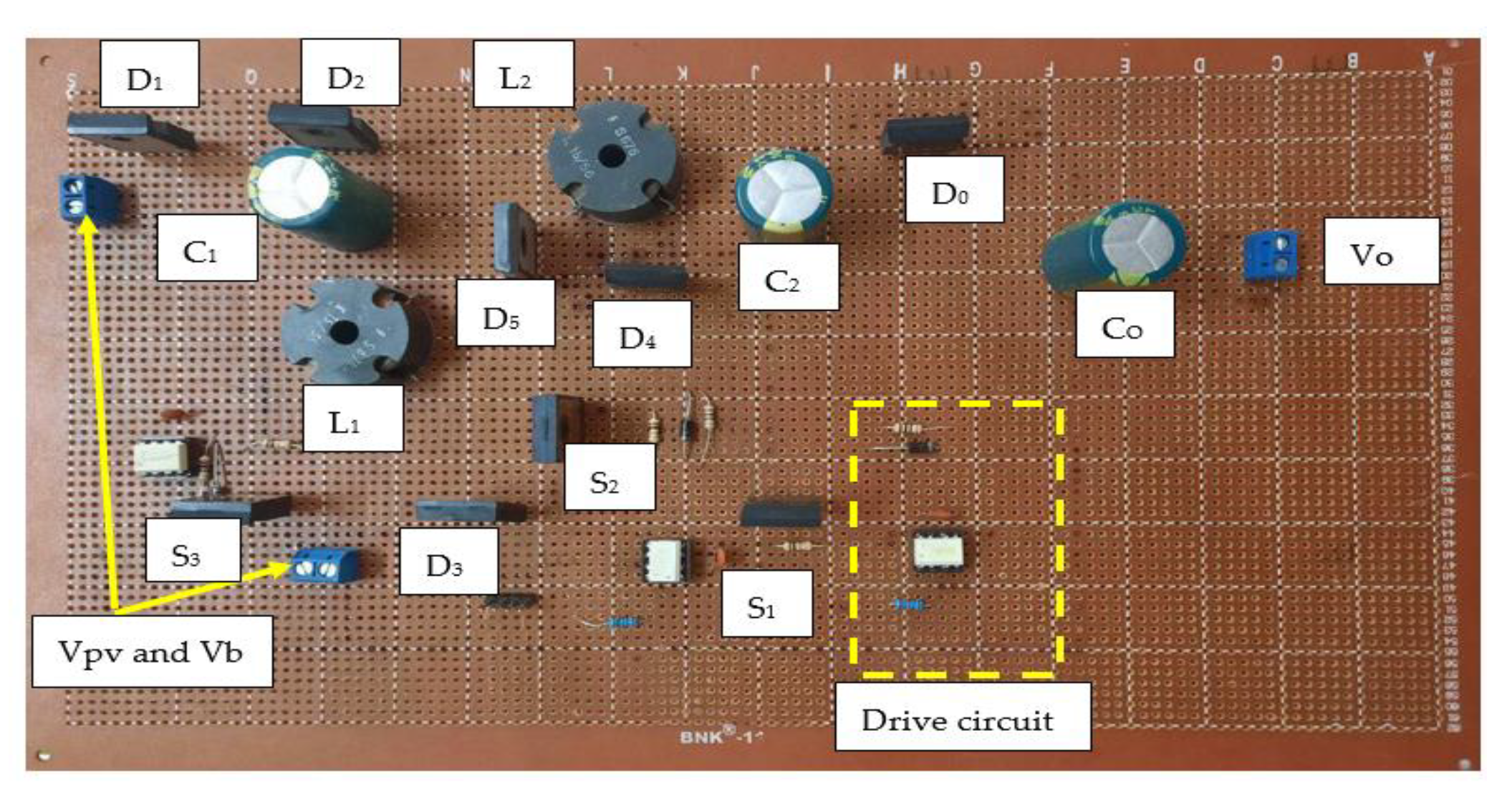
The empirical evaluation of the described system through prototype testing offers a compelling insight into the functionality of a dual-input converter designed to harness energy from both a photovoltaic solar panel emulator and a battery. The setup utilized a 12 V battery in conjunction with a 20 V solar panel emulator, effectively simulating a hybrid energy system that combines the reliability of stored energy with the sustainability of solar power. The system’s configuration was meticulously engineered to achieve an output voltage of 84.923 V and a converter output power rating of 250 W, with a switching frequency maintained at 50 kHz. This high-frequency switching is instrumental in reducing the size of the inductors and capacitors, which were carefully selected to be 670 μH for the inductors (L1 and L2) and 100 μF for the capacitors (C1, C2, and Co), optimizing the system for energy efficiency and stability, the prototype circuit of the proposed dual input converter can be shown in the Figure 28.
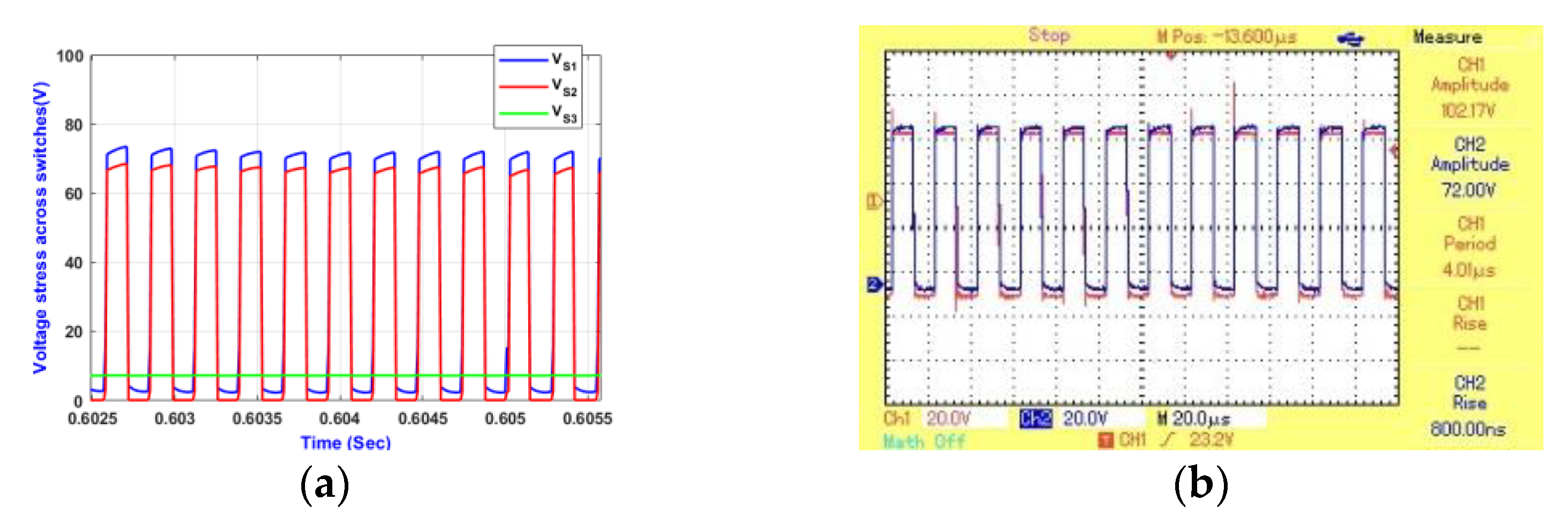
The waveforms depicted in Figure 29, Figure 30, Figure 31, Figure 32, Figure 33 and Figure 34 provide a detailed view of the system’s performance, showcasing the converter’s ability to step up the input voltage to meet the higher voltage requirements of the load. This feature is particularly notable in scenarios where the energy supplied by the solar panel exceeds the immediate demands of the load, allowing the system to operate without drawing power from the battery. Such operational efficiency extends the battery’s lifespan and emphasizes the converter’s capability to prioritize renewable energy sources over stored energy, thus aligning with sustainable energy utilization goals.
Furthermore, the system demonstrated an exceptional efficiency of 97.78%, a testament to its design and operational effectiveness. This high efficiency level ensures minimal energy loss during conversion, making the system highly suitable for applications where energy conservation and efficiency are paramount. The successful validation of the converter’s performance through theoretical analysis and empirical testing confirms its practical feasibility. It underscores its potential application in various domestic and industrial settings, where integrating renewable energy sources with traditional energy storage is desirable. The findings from this experiment highlight the advancements in converter technology, paving the way for more sustainable and efficient energy systems.

5.7. Comparative Study

Various multiport DC-DC converters are compared in Table 5. Each system’s reference numbers, including the proposed system, range from [126,127,128,129,130,131,132,133,134,135,136,137]. Each output voltage and four parameters (number of inductors (NL), number of capacitors (NC), number of switches (NS), and number of diodes (ND)) are listed in the table. The last column shows whether the systems are bidirectional or unidirectional, where “Yes” indicates bidirectionality and “No” indicates unidirectionality. As a new model, the “proposed” system is more straightforward and can function in both directions.
The proposed multiport DC-DC converter, characterized by its relatively straightforward design featuring two inductors, two capacitors, three switches, and six diodes, stands out for its bidirectional capability, allowing energy flow in both directions, which is crucial for applications like renewable energy systems, battery storage, and grid-tied systems. Its output voltage equation, V p v D 1 D 1 2 D 3 + 2 ( 1 D 1 ) 2 + V b D 3 1 D 1 1 D 3 , indicates a sophisticated relationship between duty cycles and input voltages, suggesting a need for precise control strategies to manage the complex power flow dynamics. Despite its higher diode count, which hints at a complex internal topology, the converter’s design balances simplicity in the component count with the advanced functionality afforded by its bidirectionality, making it a compelling choice for modern energy conversion and management applications.

6. Discussion and Future Recommendations

Because of their capacity to incorporate numerous renewable resources and energy storage systems into a single conversion stage, multiport DC-DC converters are gaining prominence in renewable energy applications. This integration allows for various ports to meet their energy needs more effectively. Peak shaving, PV firming, and BSS charging are standard power flow modes in these systems. The design and choice of converter structure are influenced by the specific operating states of the multiport converter, which define each mode. Significant features of these systems include optimizing grid profiles, reducing energy costs during off-peak and peak periods, and utilizing control approaches customized to the converter’s operating states. Battery storage systems are increasingly used for tasks such as PV firming and peak shaving as energy storage costs continue to decline and the practicality of renewable energy sources expands [151,152].
Future recommendations for multiport DC-DC converters in renewable energy systems emphasize the importance of ongoing development and optimization. This incorporates improving control strategies to regulate power distribution among different ports, advancing converter design to enhance efficiency, and integrating emerging technologies such as machine learning for predictive analytics. Furthermore, an increasing emphasis is on creating economical, easily expandable solutions to promote broader acceptance and the utilization of various renewable energy applications. As technology advances, these converters will have a crucial role in optimizing the capacity of renewable energy sources. There are several future recommendations as follows:
  • Power flow management among an electric vehicle’s battery, photovoltaic system, and fuel cell can be achieved with the help of advanced control algorithms. Adaptive responses to fluctuating energy demands and storage capacities are part of this process, which also involves real-time monitoring.
  • Optimal energy harvesting from PV systems, efficient energy storage in EVs, and effective use of fuel cells as a backup or supplementary power source are all areas that could benefit from better energy management.
  • Emphasize a smooth integration of these systems, focusing on electric vehicles, PV modules, and fuel cells so that the converters can efficiently balance the load and source dynamics.
  • Improved interoperability: Considering different protocols and standards, work on making multiport converters more compatible with electric vehicles, PV systems, and fuel cell technologies of all kinds.
  • Get a feel for how these technologies will affect the environment through thorough life-cycle and sustainability analyses; the goal should be to find environmentally friendly and long-lasting solutions.
  • Examining the potential interactions between these interconnected systems and the grid to enhance grid stability is an essential area of research, particularly in scenarios with a high penetration of renewable energy sources.
  • Investigate novel converter topologies that can improve system performance by effectively managing the power demands and properties of electric vehicles, PV systems, and fuel cells.
  • Dependability and longevity: Highlight the dependability and longevity of converters in a range of operating conditions, such as harsh weather, heavy usage, and extended operation.
  • Analyze the market potential, scalability, and cost–benefit analysis of integrating these technologies to drive commercial adoption and policy support. Also, consider the economic viability of the project.
  • The development and influence of standardization and regulatory frameworks is an important area to focus on to ensure these technologies’ smooth and efficient integration.

7. Conclusions

This study examined several bidirectional DC-DC converter topologies and their uses. According to this study, multiport converters, or MPCs, have demonstrated exceptional performance compared with multiple independent power supplies, especially in grid-connected setups and electric vehicles (EVs). By lowering complexity and the number of components needed, MPCs make integrating multi-output applications and hybrid energy sources easier. Furthermore, their straightforward control circuit design improves energy management between the input and the load and facilitates load regulation. MPCs are, therefore, becoming more and more critical in scenarios involving multiple inputs and outputs.
According to the literature review, no single converter topology can fully capture the advantages of low-power devices, passive components, complex control, and high reliability. Each topology has advantages and disadvantages of its own. Ongoing efforts aim to create new multiport converters for various uses. This article’s difficulties and potential paths will help create MPCs with improved performance.
A unique multiport DC-DC converter intended for stand-alone applications is also presented in this paper. By combining two sources into a single load, this converter minimizes the number of components, thereby lowering power losses and system dimensions. Its bidirectional buck–boost design connects sources and loads with different voltage and power levels with great versatility. Simulation and experimental results demonstrate the converter’s ability to maintain the boosted DC link voltage with or without PV availability.

Author Contributions

A.J.A., M.S. (Mahmood Swadi) and M.S. (Mohamed Salem) conceptualized the problem, provided the methodology and analysis, and prepared the original draft; A.B., A.R., M.K. and M.S. (Mohamed Salem) reviewed and edited this manuscript and provided valuable insights into the overall system. All authors have read and agreed to the published version of the manuscript.

Funding

This research laboratory work was funded and done at power system lab, School of Electrical and Electronic Engineering, Universiti Sains Malaysia.

Data Availability Statement

Data sharing is not applicable.

Conflicts of Interest

The authors declare no conflicts of interest.

References

  1. Gorji, S.A.; Sahebi, H.G.; Ektesabi, M.; Rad, A.B. Topologies and Control Schemes of Bidirectional Dc–Dc Power Converters: An Overview. IEEE Access 2019, 7, 117997–118019. [Google Scholar] [CrossRef]
  2. Mughis, M.A.; Sudiharto, I.; Ferdiansyah, I.; Yanaratri, D.S. Design and Implementation of Partial M-Type Zero Voltage Resonant Circuit Interleaved Bidirectional Dc–Dc Converter (Energy Storage and Load Sharing). In Proceedings of the 2018 International Electronics Symposium on Engineering Technology and Applications (IES-ETA), Bali Island, Indonesia, 29–30 October 2018. [Google Scholar]
  3. Forouzesh, M.; Siwakoti, Y.P.; Gorji, S.A.; Blaabjerg, F.; Lehman, B. Step-up Dc–Dc Converters: A Comprehensive Review of Voltage-Boosting Techniques, Topologies, and Applications. IEEE Trans. Power Electron. 2017, 32, 9143–9178. [Google Scholar] [CrossRef]
  4. Zeng, Y.; Li, H.; Zhang, Z.; Zheng, T.Q.; Shang, Z.; Qiu, Z.; Yuan, L.; Ding, Y. A Parallel-Resonant Isolated Bidirectional Dc-Dc Converter with Low Current Ripple for Battery Storage Systems. In Proceedings of the 2019 IEEE Energy Conversion Congress and Exposition (ECCE), Baltimore, MD, USA, 29 September–3 October 2019. [Google Scholar]
  5. Ma, X.; Wang, P.; Bi, H.; Wang, Z. A Bidirectional Llcl Resonant Dc-Dc Converter with Reduced Resonant Tank Currents and Reduced Voltage Stress of the Resonant Capacitor. IEEE Access 2020, 8, 125549–125564. [Google Scholar] [CrossRef]
  6. Li, Y.; Wang, Y.; Song, H. Bidirectional Dc-Dc Converter Based on Clc Network. In Proceedings of the 2019 22nd International Conference on Electrical Machines and Systems (ICEMS), Harbin, China, 11–14 August 2019. [Google Scholar]
  7. Alatai, S.; Salem, M.; Ishak, D.; Das, H.S.; Alhuyi Nazari, M.; Bughneda, A.; Kamarol, M. A Review on State-of-the-Art Power Converters: Bidirectional, Resonant, Multilevel Converters and Their Derivatives. Appl. Sci. 2021, 11, 10172. [Google Scholar] [CrossRef]
  8. Ravi, D.; Reddy, B.M.; Shimi, S.; Samuel, P. Bidirectional Dc to Dc Converters: An Overview of Various Topologies, Switching Schemes and Control Techniques. Int. J. Eng. Technol. 2018, 7, 360–365. [Google Scholar] [CrossRef]
  9. Yanna, V.S.R.; Bhajana, V.S.K.; Drabek, P.; Popuri, M. A Novel Soft-Switching Bidirectional Dc-Dc Converter for Energy Storage Applications. In Proceedings of the 2020 International Conference on Applied Electronics (AE), Pilsen, Czech Republic, 8–9 September 2020. [Google Scholar]
  10. Wang, H.; Xu, Z.; Ge, X.; Liao, Y.; Yang, Y.; Zhang, Y.; Yao, B.; Chai, Y. A Junction Temperature Monitoring Method for Igbt Modules Based on Turn-Off Voltage with Convolutional Neural Networks. IEEE Trans. Power Electron. 2023, 38, 10313–10328. [Google Scholar] [CrossRef]
  11. Salem, M.; Jusoh, A.; Idris, N.R.N. Implementing Buck Converter for Battery Charger Using Soft Switching Techniques. In Proceedings of the 2013 IEEE 7th International Power Engineering and Optimization Conference (PEOCO), Langkawi Island, Malaysia, 3–4 June 2013. [Google Scholar]
  12. Xiao, S.; Wang, Z.; Wu, G.; Guo, Y.; Gao, G.; Zhang, X.; Cao, Y.; Zhang, Y.; Yu, J.; Liu, P. The Impact Analysis of Operational Overvoltage on Traction Transformers for High-Speed Trains Based on the Improved Capacitor Network Methodology. IEEE Trans. Transp. Electrif. 2023. [Google Scholar] [CrossRef]
  13. Schupbach, R.M.; Balda, J.C. Comparing Dc-Dc Converters for Power Management in Hybrid Electric Vehicles. In Proceedings of the IEEE International Electric Machines and Drives Conference, IEMDC’03, Madison, WI, USA, 1–4 June 2003. [Google Scholar]
  14. Cuk, S. A New Zero-Ripple Switching Dc-to-Dc Converter and Integrated Magnetics. IEEE Trans. Magn. 1983, 19, 57–75. [Google Scholar] [CrossRef]
  15. Zhou, S.; Zhou, G.; He, M.; Mao, S.; Zhao, H.; Liu, G. Stability Effect of Different Modulation Parameters in Voltage-Mode Pwm Control for Ccm Switching Dc-Dc Converter. IEEE Trans. Transp. Electrif. 2023. [Google Scholar] [CrossRef]
  16. Waffler, S.; Kolar, J.W. A Novel Low-Loss Modulation Strategy for High-Power Bidirectional Buck+Boost Converters. IEEE Trans. Power Electron. 2009, 24, 1589–1599. [Google Scholar] [CrossRef]
  17. Waffler, S.; Biela, J.; Kolar, J.W. Output Ripple Reduction of an Automotive Multi-Phase Bi-Directional Dc-Dc Converter. In Proceedings of the 2009 IEEE Energy Conversion Congress and Exposition, San Jose, CA, USA, 20–24 September 2009. [Google Scholar]
  18. Shahin, M. Analysis of Bidirectional Sepic/Zeta Converter with Coupled Inductor. In Proceedings of the 2015 International Conference on Technological Advancements in Power and Energy (TAP Energy), Kollam, India, 24–26 June 2015. [Google Scholar]
  19. Kim, I.-D.; Lee, Y.-H.; Min, B.-H.; Nho, E.-C.; Ahn, J.-W. Design of Bidirectional Pwm Sepic/Zeta Dc-Dc Converter. In Proceedings of the 2007 7th Internatonal Conference on Power Electronics, Daegu, South Korea, 22–26 October 2007. [Google Scholar]
  20. Zhou, S.; Zhou, G.; Liu, X.; Zhao, H. Dynamic Freewheeling Control for Sido Buck Converter with Fast Transient Performance, Minimized Cross-Regulation, and High Efficiency. IEEE Trans. Ind. Electron. 2022, 70, 1467–1477. [Google Scholar] [CrossRef]
  21. Liu, S.; Liu, C. Virtual-Vector-Based Robust Predictive Current Control for Dual Three-Phase Pmsm. IEEE Trans. Ind. Electron. 2020, 68, 2048–2058. [Google Scholar] [CrossRef]
  22. Alatai, S.; Salem, M.; Ishak, D.; Kamarol, M.; Jamil, M.; Bughneda, A. Design and Analysis of Five-Level Cascaded Llc Resonant Converter. In Proceedings of the 2020 IEEE International Conference on Power and Energy (PECon), Penang, Malaysia, 7–8 December 2020. [Google Scholar]
  23. Salem, M.; Jusoh, A.; Idris, N.R.N.; Tan, C.W.; Alhamrouni, I. Phase-Shifted Series Resonant Dc-Dc Converter for Wide Load Variations Using Variable Frequency Control. In Proceedings of the 2017 IEEE Conference on Energy Conversion (CENCON), Kuala Lumpur, Malaysia, 30–31 October 2017. [Google Scholar]
  24. Chung, H.S.-H.; Ioinovici, A.; Cheung, W.-L. Generalized Structure of Bi-Directional Switched-Capacitor Dc/Dc Converters. IEEE Trans. Circuits Syst. I Fundam. Theory Appl. 2003, 50, 743–753. [Google Scholar] [CrossRef]
  25. Li, J.; Sullivan, C.R.; Schultz, A. Coupled-Inductor Design Optimization for Fast-Response Low-Voltage Dc-Dc Converters. In Proceedings of the APEC. Seventeenth Annual IEEE Applied Power Electronics Conference and Exposition (Cat. No. 02CH37335), Dallas, TX, USA, 10–14 March 2002. [Google Scholar]
  26. Wong, P.-L.; Wu, Q.; Xu, P.; Yang, B.; Lee, F.C. Investigating Coupling Inductors in the Interleaving Qsw Vrm. In Proceedings of the APEC 2000. Fifteenth Annual IEEE Applied Power Electronics Conference and Exposition (Cat. No. 00CH37058), New Orleans, LA, USA, 6–10 February 2000. [Google Scholar]
  27. Ni, L.; Patterson, D.J.; Hudgins, J.L. High Power Current Sensorless Bidirectional 16-Phase Interleaved Dc-Dc Converter for Hybrid Vehicle Application. IEEE Trans. Power Electron. 2011, 27, 1141–1151. [Google Scholar] [CrossRef]
  28. Garcia, O.; Zumel, P.; De Castro, A.; Cobos, A. Automotive Dc-Dc Bidirectional Converter Made with Many Interleaved Buck Stages. IEEE Trans. Power Electron. 2006, 21, 578–586. [Google Scholar] [CrossRef]
  29. Garinto, D. Multi-Interleaved Zero-Ripple Vrm to Power Future Microprocessors. In Proceedings of the 2007 European Conference on Power Electronics and Applications, Aalborg, Denmark, 2–5 September 2007. [Google Scholar]
  30. Xu, P.; Lan, D.; Wang, F.; Shin, I.J.E. In-Memory Computing Integrated Structure Circuit Based on Nonvolatile Flash Memory Unit. Electronics 2023, 12, 3155. [Google Scholar] [CrossRef]
  31. Sunkara, S.; Kondrath, N. Design and Pspice Simulation of Synchronous Bidirectional Pwm Dc-Dc Buck-Boost Converter Operating in Ccm. In Proceedings of the 2013 Annual IEEE India Conference (INDICON), Mumbai, India, 13–15 December 2013. [Google Scholar]
  32. Kim, E.-S.; Kim, C.-J.; Kim, Y.-T. Development of Bidirectional Ac-Dc Converter for Energy Storage Systems. In Proceedings of the 2019 22nd International Conference on Electrical Machines and Systems (ICEMS), Harbin, China, 11–14 August 2019. [Google Scholar]
  33. Rahman, M.M.; Uddin, M.N.; Islam, M.K. Performance Enhancement of a Bi-Directional Dc-Dc Converter Using a Ćuk Converter for Electric Vehicle Applications. In Proceedings of the 2015 IEEE 28th Canadian Conference on Electrical and Computer Engineering (CCECE), Halifax, NS, Canada, 3–6 May 2015. [Google Scholar]
  34. Bhajana, V.S.K.; Drabek, P. A Novel Zcs Non-Isolated Bidirectional Buck-Boost Dc-Dc Converter for Energy Storage Applications. In Proceedings of the 2015 IEEE 24th International Symposium on Industrial Electronics (ISIE), Rio de Janeiro, Brazil, 3–5 June 2015. [Google Scholar]
  35. Lee, Y.-S.; Cheng, G.-T. Quasi-Resonant Zero-Current-Switching Bidirectional Converter for Battery Equalization Applications. IEEE Trans. Power Electron. 2006, 21, 1213–1224. [Google Scholar] [CrossRef]
  36. Osman, I.; Xiao, D.; Rahman, M. Analysis of a Cascaded High-Boost Non-Isolated Dc-Dc Converter with Bidirectional Power Flow. In Proceedings of the 2016 IEEE 2nd Annual Southern Power Electronics Conference (SPEC), Auckland, New Zealand, 5–8 December 2016. [Google Scholar]
  37. Vazquez, J.; Salmeron, P. Active Power Filter Control Using Neural Network Technologies. IEE Proc.-Electr. Power Appl. 2003, 150, 139–145. [Google Scholar] [CrossRef]
  38. Mu, Y.; Yang, X.; Xue, Y.; Lin, Z.; Zheng, T.Q.; Igarashi, S. A Bidirectional Switched-Capacitor Based Ac-Ac Resonant Converter. In Proceedings of the 2016 IEEE 11th Conference on Industrial Electronics and Applications (ICIEA), Hefei, China, 5–7 June 2016. [Google Scholar]
  39. Jangir, P.; Kumar, R. Closed-Loop Control Analysis of Interleaved Non-Isolated Bidirectional Dc-Dc Converter. In Proceedings of the 2017 IEEE International WIE Conference on Electrical and Computer Engineering (WIECON-ECE), Dehradun, India, 18–19 December 2017. [Google Scholar]
  40. Paul, P.; Jose, B.R.; Shahana, T.; Abraham, C.; Mathew, J. Isolated Switched Boost Dc-Dc Converter with Coupled Inductor and Transformer. In Proceedings of the TENCON 2019—2019 IEEE Region 10 Conference (TENCON), Kochi, India, 17–20 October 2019. [Google Scholar]
  41. Kheraluwala, M.; Gascoigne, R.W.; Divan, D.M.; Baumann, E.D. Performance Characterization of a High-Power Dual Active Bridge Dc-to-Dc Converter. IEEE Trans. Ind. Appl. 1992, 28, 1294–1301. [Google Scholar] [CrossRef]
  42. Sorrentino, N.; Barone, G.; Brusco, G.; Motta, M.; Menniti, D.; Pinnarelli, A.; Burgio, A. A Dual Active Bridge Dc-Dc Converter for Application in a Smart User Network. In Proceedings of the 2014 Australasian Universities Power Engineering Conference (AUPEC), Perth, Australia, 28 September–1 October 2014. [Google Scholar]
  43. Kumar, A.; Bhat, A.; Agarwal, P. Comparative Analysis of Dual Active Bridge Isolated Dc to Dc Converter with Flyback Converters for Bidirectional Energy Transfer. In Proceedings of the 2017 Recent Developments in Control, Automation & Power Engineering (RDCAPE), Noida, India, 26–27 October 2017. [Google Scholar]
  44. Kumar, B.M.; Kumar, A.; Bhat, A.; Agarwal, P. Comparative Study of Dual Active Bridge Isolated Dc to Dc Converter with Single Phase Shift and Dual Phase Shift Control Techniques. In Proceedings of the 2017 Recent Developments in Control, Automation & Power Engineering (RDCAPE), Noida, India, 26–27 October 2017. [Google Scholar]
  45. Peng, F.Z.; Li, H.; Su, G.-J.; Lawler, J.S. A New Zvs Bidirectional Dc-Dc Converter for Fuel Cell and Battery Application. IEEE Trans. Power Electron. 2004, 19, 54–65. [Google Scholar] [CrossRef]
  46. Jung, J.-H.; Kim, H.-S.; Ryu, M.-H.; Baek, J.-W. Design Methodology of Bidirectional Cllc Resonant Converter for High-Frequency Isolation of Dc Distribution Systems. IEEE Trans. Power Electron. 2012, 28, 1741–1755. [Google Scholar] [CrossRef]
  47. Alatai, S.; Salem, M.; Ishak, D.; Bughneda, A.; Kamarol, M.; Luta, D.N. Cascaded Multi-Level Inverter for Battery Charging-Discharging Using Buck-Boost Switch. In Proceedings of the 2021 IEEE Industrial Electronics and Applications Conference (IEACon), Penang, Malaysia, 22–23 November 2021. [Google Scholar]
  48. Yang, Y.; Zhang, Z.; Zhou, Y.; Wang, C.; Zhu, H. Design of a Simultaneous Information and Power Transfer System Based on a Modulating Feature of Magnetron. IEEE Trans. Microw. Theory Tech. 2022, 71, 907–915. [Google Scholar] [CrossRef]
  49. Zhang, F.; Yan, Y. Novel Forward-Flyback Hybrid Bidirectional Dc-Dc Converter. IEEE Trans. Power Electron. 2009, 56, 1578–1584. [Google Scholar]
  50. Kashif, M. Bidirectional Flyback Dc-Dc Converter for Hybrid Electric Vehicle: Utility, Working and Pspice Computer Model. In Proceedings of the 2012 Asia Pacific Conference on Postgraduate Research in Microelectronics and Electronics, Hyderabad, India, 5–7 December 2012. [Google Scholar]
  51. Wang, Y.; Xia, F.; Wang, Y.; Xiao, X. Harmonic Transfer Function Based Single-Input Single-Output Impedance Modeling of Lcchvdc Systems. J. Mod. Power Syst. Clean Energy 2023. [Google Scholar]
  52. Aboulnaga, A.; Emadi, A. Performance Evaluation of the Isolated Bidirectional Cuk Converter with Integrated Magnetics. In Proceedings of the 2004 IEEE 35th Annual Power Electronics Specialists Conference (IEEE Cat. No. 04CH37551), Aachen, Germany, 20–25 June 2004. [Google Scholar]
  53. Mohammadi, M.R.; Farzanehfard, H. A New Bidirectional Zvs-Pwm Cuk Converter with Active Clamp. In Proceedings of the 2011 19th Iranian Conference on Electrical Engineering, Tehran, Iran, 17–19 May 2011. [Google Scholar]
  54. Wang, Y.; Chen, P.; Yong, J.; Xu, W.; Xu, S.; Liu, K. A Comprehensive Investigation on the Selection of High-Pass Harmonic Filters. IEEE Trans. Power Deliv. 2022, 37, 4212–4226. [Google Scholar] [CrossRef]
  55. Xiangli, K.; Li, S.; Smedley, K. Analysis and Modelling of a Bidirectional Push-Pull Converter with Pwm Plus Phase-Shift Control. In Proceedings of the IECON 2016—42nd Annual Conference of the IEEE Industrial Electronics Society, Florence, Italy, 23–26 October 2016. [Google Scholar]
  56. Tao, H.; Duarte, J.L.; Hendrix, M.A. Three-Port Triple-Half-Bridge Bidirectional Converter with Zero-Voltage Switching. IEEE Trans. Power Electron. 2008, 23, 782–792. [Google Scholar]
  57. Lu, Y.-J.; Liang, T.-J.; Lin, C.-H.; Chen, K.-H. Design and Implementation of a Bidirectional Dc-Dc Forward/Flyback Converter with Leakage Energy Recycled. In Proceedings of the 2017 Asian Conference on Energy, Power and Transportation Electrification (ACEPT), Singapore, 24–26 October 2017. [Google Scholar]
  58. Shirkhani, M.; Tavoosi, J.; Danyali, S.; Sarvenoee, A.K.; Abdali, A.; Mohammadzadeh, A.; Zhang, C. A Review on Microgrid Decentralized Energy/Voltage Control Structures and Methods. Energy Rep. 2023, 10, 368–380. [Google Scholar] [CrossRef]
  59. Vieira, A.; Mazza, L.; Antunes, F.; Oliveira, D. Bidirectional Dual-Active-Bridge Dc-Dc Converter for Vehicle-to-Grid Applications in Dc Microgrids. In Proceedings of the 2018 Simposio Brasileiro de Sistemas Eletricos (SBSE), Niteroi, Brazil, 12–16 May 2018. [Google Scholar]
  60. Bhajana, V.S.K.; Reddy, S.R. A Novel Zvs-Zcs Bidirectional Dc-Dc Converter for Fuel Cell and Battery Application. In Proceedings of the 2009 International Conference on Power Electronics and Drive Systems (PEDS), Taipei, Taiwan, 2–5 November 2009. [Google Scholar]
  61. Sun, Q.; Lyu, G.; Liu, X.; Niu, F.; Gan, C. Virtual Current Compensation-Based Quasi-Sinusoidal-Wave Excitation Scheme for Switched Reluctance Motor Drives. IEEE Trans. Ind. Electron. 2023, 1–12. [Google Scholar] [CrossRef]
  62. Shen, Y.; Liu, D.; Liang, W.; Zhang, X. Current Reconstruction of Three-Phase Voltage Source Inverters Considering Current Ripple. IEEE Trans. Transp. Electrif. 2022, 9, 1416–1427. [Google Scholar] [CrossRef]
  63. Salem, M.; Richelli, A.; Yahya, K.; Hamidi, M.N.; Ang, T.-Z.; Alhamrouni, I. A Comprehensive Review on Multilevel Inverters for Grid-Tied System Applications. Energies 2022, 15, 6315. [Google Scholar] [CrossRef]
  64. Thummala, P.; Maksimovic, D.; Zhang, Z.; Andersen, M.A.E. Digital Control of a High-Voltage (2.5 Kv) Bidirectional Dc–Dc Flyback Converter for Driving a Capacitive Incremental Actuator. IEEE Trans. Power Electron. 2016, 31, 8500–8516. [Google Scholar] [CrossRef]
  65. Kim, H.-W.; Park, J.-H. Isolated Bidirectional Switched-Capacitor Flyback Converter. In Proceedings of the 2014 International Power Electronics and Application Conference and Exposition, Shanghai, China, 5–8 November 2014. [Google Scholar]
  66. Li, C.; Herrera, L.; Jia, J.; Fu, L.; Isurin, A.; Cook, A.; Huang, Y.; Wang, J. Design and Implementation of a Bidirectional Isolated Ćuk Converter for Low-Voltage and High-Current Automotive Dc Source Applications. IEEE Trans. Veh. Technol. 2013, 63, 2567–2577. [Google Scholar] [CrossRef]
  67. Ling, R.; Dan, Q.; Wang, L.; Li, D. Energy Bus-Based Equalization Scheme with Bi-Directional Isolated Cuk Equalizer for Series Connected Battery Strings. In Proceedings of the 2015 IEEE Applied Power Electronics Conference and Exposition (APEC), Charlotte, NC, USA, 15–19 March 2015. [Google Scholar]
  68. Kosenko, R.; Zakis, J.; Blinov, A.; Chub, A.; Veligorskyi, O. Full Soft-Switching Bidirectional Isolated Current-Fed Dual Inductor Push-Pull Dc-Dc Converter for Battery Energy Storage Applications. In Proceedings of the 2016 57th International Scientific Conference on Power and Electrical Engineering of Riga Technical University (RTUCON), Riga, Latvia, 13–14 October 2016. [Google Scholar]
  69. Mukhtar, N.M.; Lu, D.D.-C. An Isolated Bidirectional Forward Converter with Integrated Output Inductor-Transformer Structure. In Proceedings of the 2018 IEEE 4th Southern Power Electronics Conference (SPEC), Singapore, 10–13 December 2018. [Google Scholar]
  70. Park, K.-B.; Moon, G.-W.; Youn, M.-J. Two-Switch Active-Clamp Forward Converter with One Clamp Diode and Delayed Turnoff Gate Signal. IEEE Trans. Ind. Electron. 2011, 58, 4768–4772. [Google Scholar] [CrossRef]
  71. Das, D.; Weise, N.; Basu, K.; Baranwal, R.; Mohan, N. A Bidirectional Soft-Switched Dab-Based Single-Stage Three-Phase Ac–Dc Converter for V2g Application. IEEE Trans. Transp. Electrif. 2018, 5, 186–199. [Google Scholar] [CrossRef]
  72. Han, W.; Corradini, L. General Closed-Form Zvs Analysis of Dual-Bridge Series Resonant Dc–Dc Converters. IEEE Trans. Power Electron. 2018, 34, 9289–9302. [Google Scholar] [CrossRef]
  73. He, P.; Khaligh, A. Comprehensive Analyses and Comparison of 1 Kw Isolated Dc–Dc Converters for Bidirectional Ev Charging Systems. IEEE Trans. Transp. Electrif. 2016, 3, 147–156. [Google Scholar] [CrossRef]
  74. Morrison, R.; Egan, M.G. A New Power-Factor-Corrected Single-Transformer Ups Design. IEEE Trans. Ind. Appl. 2000, 36, 171–179. [Google Scholar] [CrossRef]
  75. Du, Y.; Lukic, S.; Jacobson, B.; Huang, A. Review of High Power Isolated Bi-Directional Dc-Dc Converters for Phev/Ev Dc Charging Infrastructure. In Proceedings of the 2011 IEEE Energy Conversion Congress and Exposition, Phoenix, AZ, USA, 17–22 September 2011. [Google Scholar]
  76. Yuan, J.; Dorn-Gomba, L.; Callegaro, A.D.; Reimers, J.; Emadi, A. A Review of Bidirectional on-Board Chargers for Electric Vehicles. IEEE Access 2021, 9, 51501–51518. [Google Scholar] [CrossRef]
  77. Bassa de los Mozos, A.; Chandra Mouli, G.R.; Bauer, P. Evaluation of Topologies for a Solar Powered Bidirectional Electric Vehicle Charger. IET Power Electron. 2019, 12, 3675–3687. [Google Scholar] [CrossRef]
  78. Leite, R.S.; Afonso, J.L.; Monteiro, V. A Novel Multilevel Bidirectional Topology for on-Board Ev Battery Chargers in Smart Grids. Energies 2018, 11, 3453. [Google Scholar] [CrossRef]
  79. Wang, H.; Sun, W.; Jiang, D.; Qu, R. A Mtpa and Flux-Weakening Curve Identification Method Based on Physics-Informed Network without Calibration. IEEE Trans. Power Electron. 2023, 38, 12370–12375. [Google Scholar] [CrossRef]
  80. Yang, X.; Wang, X.; Wang, S.; Wang, K.; Sial, M.B. Finite-Time Adaptive Dynamic Surface Synchronization Control for Dual-Motor Servo Systems with Backlash and Time-Varying Uncertainties. ISA Trans. 2023, 137, 248–262. [Google Scholar] [CrossRef] [PubMed]
  81. Hosseinpour, M.; Seifi, A.; Rahimian, M.M. A Bidirectional Diode Containing Multilevel Inverter Topology with Reduced Switch Count and Driver. Int. J. Circuit Theory 2020, 48, 1766–1785. [Google Scholar] [CrossRef]
  82. Kosenko, R.; Blinov, A.; Vinnikov, D.; Chub, A. Asymmetric Snubberless Current-Fed Full-Bridge Isolated Dc-Dc Converters. Sci. J. Riga. Tech. Univ.-Electr. Control Commun. Eng. 2018, 14, 5–11. [Google Scholar] [CrossRef]
  83. Karthikeyan, B.; Sundararaju, K.; Palanisamy, R.; Manivasagam, R.; Hossain, I.; Bajaj, M.; Shouran, M.; Kamel, S. A Dual Input Single Output Non-Isolated Dc-Dc Converter for Multiple Sources Electric Vehicle Applications. Front. Energy Res. 2022, 10, 979539. [Google Scholar] [CrossRef]
  84. Lu, L.; Wu, W.; Gao, Y.; Pan, C.; Yu, X.; Zhang, C.; Jin, Z. Study on Current Discrepancy and Redistribution of Hts Non-Insulation Closed-Loop Coils During Charging/Discharging and Subsequent Transient Process toward Steady-State Operation. Supercond. Sci. Technol. 2022, 35, 095001. [Google Scholar] [CrossRef]
  85. Gao, Y.; Doppelbauer, M.; Ou, J.; Qu, R. Design of a Double-Side Flux Modulation Permanent Magnet Machine for Servo Application. IEEE J. Emerg. Sel. Top. Power Electron. 2021, 10, 1671–1682. [Google Scholar] [CrossRef]
  86. Lavanya, A.; Jegatheesan, R.; Vijayakumar, K. Design of Novel Dual Input Dc–Dc Converter for Energy Harvesting System in Iot Sensor Nodes. Wirel. Pers. Commun. 2021, 117, 2793–2808. [Google Scholar] [CrossRef]
  87. Kim, S.-H.; Byun, H.-J.; Yi, J.; Won, C.-Y. A Bi-Directional Dual-Input Dual-Output Converter for Voltage Balancer in Bipolar Dc Microgrid. Energies 2022, 15, 5043. [Google Scholar] [CrossRef]
  88. Suresh, K.; Bharatiraja, C.; Chellammal, N.; Tariq, M.; Chakrabortty, R.K.; Ryan, M.J.; Alamri, B. A Multifunctional Non-Isolated Dual Input-Dual Output Converter for Electric Vehicle Applications. IEEE Access 2021, 9, 64445–64460. [Google Scholar] [CrossRef]
  89. Fernão Pires, V.; Cordeiro, A.; Foito, D.; Silva, J.F. A High-Voltage Gain Non-Isolated Dc–Dc Converter Designed for Bipolar Dc Microgrids. Electr. Power Compon. Syst. 2023, 51, 1171–1181. [Google Scholar] [CrossRef]
  90. Kim, S.; Nam, H.-T.; Cha, H.; Kim, H.-G. Investigation of Self-Output Voltage Balancing in Input-Parallel Output-Series Dc–Dc Converter. IEEE J. Emerg. Sel. Top. Power Electron. 2019, 8, 2850–2860. [Google Scholar] [CrossRef]
  91. Aravind, R.; Chokkalingam, B.; Mihet-Popa, L. A Transformerless Non-Isolated Multi-Port Dc–Dc Converter for Hybrid Energy Applications. IEEE Access 2023, 11, 52050–52065. [Google Scholar] [CrossRef]
  92. Lin, X.; Liu, Y.; Yu, J.; Yu, R.; Zhang, J.; Wen, H. Stability Analysis of Three-Phase Grid-Connected Inverter under the Weak Grids with Asymmetrical Grid Impedance by Ltp Theory in Time Domain. Int. J. Electr. Power Energy Syst. 2022, 142, 108244. [Google Scholar] [CrossRef]
  93. Lin, X.; Wen, Y.; Yu, R.; Yu, J.; Wen, H. Improved Weak Grids Synchronization Unit for Passivity Enhancement of Grid-Connected Inverter. IEEE J. Emerg. Sel. Top. Power Electron. 2022, 10, 7084–7097. [Google Scholar] [CrossRef]
  94. Mohseni, P.; Hosseini, S.H.; Sabahi, M.; Jalilzadeh, T.; Maalandish, M. A New High Step-up Multi-Input Multi-Output Dc–Dc Converter. IEEE Trans. Ind. Electron. 2018, 66, 5197–5208. [Google Scholar] [CrossRef]
  95. Dezhbord, M.; Mohseni, P.; Hosseini, S.H.; Mirabbasi, D.; Islam, M.R. A High Step-up Three-Port Dc–Dc Converter with Reduced Voltage Stress for Hybrid Energy Systems. IEEE J. Emerg. Sel. Top. Ind. Electron. 2022, 3, 998–1009. [Google Scholar] [CrossRef]
  96. Chen, C.; Wu, X.; Yuan, X.; Zheng, X. A New Technique for the Subdomain Method in Predicting Electromagnetic Performance of Surface-Mounted Permanent Magnet Motors with Shaped Magnets and a Quasi-Regular Polygon Rotor Core. IEEE Trans. Energy Convers. 2022, 38, 1396–1409. [Google Scholar] [CrossRef]
  97. Li, S.; Zhao, X.; Liang, W.; Hossain, T.; Zhang, Z. A Fast and Accurate Calculation Method of Line Breaking Power Flow Based on Taylor Expansion. Front. Energy Res. 2022, 10, 943946. [Google Scholar] [CrossRef]
  98. Zhang, X.; Gong, L.; Zhao, X.; Li, R.; Yang, L.; Wang, B. Voltage and Frequency Stabilization Control Strategy of Virtual Synchronous Generator Based on Small Signal Model. Energy Rep. 2023, 9, 583–590. [Google Scholar] [CrossRef]
  99. Song, X.; Wang, H.; Ma, X.; Yuan, X.; Wu, X. Robust Model Predictive Current Control for a Nine-Phase Open-End Winding Pmsm with High Computational Efficiency. IEEE Trans. Power Electron. 2023, 38, 13933–13943. [Google Scholar] [CrossRef]
  100. Liu, S.; Liu, C. Direct Harmonic Current Control Scheme for Dual Three-Phase Pmsm Drive System. IEEE Trans. Ind. Electron. 2021, 36, 11647–11657. [Google Scholar] [CrossRef]
  101. Huang, N.; Chen, Q.; Cai, G.; Xu, D.; Zhang, L.; Zhao, W. Fault Diagnosis of Bearing in Wind Turbine Gearbox under Actual Operating Conditions Driven by Limited Data with Noise Labels. IEEE Trans. Instrum. Meas. 2020, 70, 3502510. [Google Scholar] [CrossRef]
  102. Sun, K.; Zhang, L.; Xing, Y.; Guerrero, J.M. A Distributed Control Strategy Based on Dc Bus Signaling for Modular Photovoltaic Generation Systems with Battery Energy Storage. IEEE Trans. Power Electron. 2011, 26, 3032–3045. [Google Scholar] [CrossRef]
  103. Rehman, Z.; Al-Bahadly, I.; Mukhopadhyay, S. Multiinput Dc–Dc Converters in Renewable Energy Applications–An Overview. Renew. Sustain. Energy Rev. 2015, 41, 521–539. [Google Scholar] [CrossRef]
  104. Qian, Z.; Abdel-Rahman, O.; Al-Atrash, H.; Batarseh, I. Modeling and Control of Three-Port Dc/Dc Converter Interface for Satellite Applications. IEEE Trans. Power Electron. 2009, 25, 637–649. [Google Scholar] [CrossRef]
  105. Nasiri, A.; Nie, Z.; Bekiarov, S.B.; Emadi, A. An on-Line Ups System with Power Factor Correction and Electric Isolation Using Bifred Converter. IEEE Trans. Ind. Electron. 2008, 55, 722–730. [Google Scholar] [CrossRef]
  106. Zhang, Z.; Thomsen, O.C.; Andersen, M.A.E.; Nielsen, H.R. Dual-Input Isolated Full-Bridge Boost Dc–Dc Converter Based on the Distributed Transformers. IET Power Electron. 2012, 5, 1074–1083. [Google Scholar] [CrossRef]
  107. Zhang, Z.; Thomsen, O.C.; Andersen, M.A.E. Modeling and Control of a Dual-Input Isolated Full-Bridge Boost Converter. In Proceedings of the 2012 Twenty-Seventh Annual IEEE Applied Power Electronics Conference and Exposition (APEC), Orlando, FL, USA, 5–9 February 2012. [Google Scholar]
  108. Yalla, S.P.; Subudhi, P.S.; Ramachandaramurthy, V.K. Topological Review of Hybrid Res Based Multi-Port Converters. IET Renew. Power Gener. 2022, 16, 1087–1106. [Google Scholar] [CrossRef]
  109. Zhang, N.; Sutanto, D.; Muttaqi, K.M. A Review of Topologies of Three-Port Dc–Dc Converters for the Integration of Renewable Energy and Energy Storage System. Renew. Sustain. Energy Rev. 2016, 56, 388–401. [Google Scholar] [CrossRef]
  110. Yalamanchili, K.P.; Ferdowsi, M. Review of Multiple Input Dc-Dc Converters for Electric and Hybrid Vehicles. In Proceedings of the 2005 IEEE Vehicle Power and Propulsion Conference, Chicago, IL, USA, 7 September 2005. [Google Scholar]
  111. Chen, Y.-M.; Liu, Y.-C.; Lin, S.-H. Double-Input Pwm Dc/Dc Converter for High-/Low-Voltage Sources. IEEE Trans. Ind. Electron. 2006, 53, 1538–1545. [Google Scholar] [CrossRef]
  112. Belloni, M.; Bonizzoni, E.; Maloberti, F. On the Design of Single-Inductor Double-Output Dc–Dc Buck, Boost and Buck-Boost Converters. In Proceedings of the 2008 15th IEEE International Conference on Electronics, Circuits and Systems, St. Julian’s, Malta, 31 August–3 September 2008. [Google Scholar]
  113. Ray, O.; Josyula, A.P.; Mishra, S.; Joshi, A. Integrated Dual-Output Converter. IEEE Trans. Ind. Electron. 2014, 62, 371–382. [Google Scholar] [CrossRef]
  114. Hosseini, S.; Haghighian, S.K.; Danyali, S.; Aghazadeh, H. Multi-Input Dc Boost Converter Supplied by a Hybrid Pv/Wind Turbine Power Systems for Street Lighting Application Connected to the Grid. In Proceedings of the 2012 47th International Universities Power Engineering Conference (UPEC), London, UK, 4–7 September 2012. [Google Scholar]
  115. Nejabatkhah, F.; Danyali, S.; Hosseini, S.H.; Sabahi, M.; Niapour, S.M. Modeling and Control of a New Three-Input Dc–Dc Boost Converter for Hybrid Pv/Fc/Battery Power System. IEEE Trans. Ind. Electron. 2011, 27, 2309–2324. [Google Scholar] [CrossRef]
  116. Wu, H.; Sun, K.; Ding, S.; Xing, Y. Topology Derivation of Nonisolated Three-Port Dc–Dc Converters from Dic and Doc. IEEE Trans. Power Electron. 2012, 28, 3297–3307. [Google Scholar] [CrossRef]
  117. Wu, H.; Xing, Y.; Xia, Y.; Sun, K. A Family of Non-Isolated Three-Port Converters for Stand-Alone Renewable Power System. In Proceedings of the IECON 2011—37th Annual Conference of the IEEE Industrial Electronics Society, Melbourne, Australia, 7–10 November 2011. [Google Scholar]
  118. Ding, S.; Wu, H.; Xing, Y.; Fang, Y.; Ma, X. Topology and Control of a Family of Non-Isolated Three-Port Dc-Dc Converters with a Bidirectional Cell. In Proceedings of the 2013 Twenty-Eighth Annual IEEE Applied Power Electronics Conference and Exposition (APEC), Long Beach, CA, USA, 17–21 March 2013. [Google Scholar]
  119. Chen, Y.; Wen, G.; Peng, L.; Kang, Y.; Chen, J. A Family of Cost-Efficient Non-Isaolated Single-Inductor Three-Port Converters for Low Power Stand-Alone Renewable Power Applications. In Proceedings of the 2013 Twenty-Eighth Annual IEEE Applied Power Electronics Conference and Exposition (APEC), Long Beach, CA, USA, 17–21 March 2013. [Google Scholar]
  120. Chen, Y.; Zhang, P.; Zou, X.; Kang, Y. Dynamical Modeling of the Non-Isolated Single-Inductor Three-Port Converter. In Proceedings of the 2014 IEEE Applied Power Electronics Conference and Exposition-APEC 2014, Fort Worth, TX, USA, 16–20 March 2014. [Google Scholar]
  121. Vazquez, N.; Sanchez, C.; Hernandez, C.; Vazquez, E.; Lesso, R. A Three Port Converter for Renewable Energy Applications. In Proceedings of the 2011 IEEE International Symposium on Industrial Electronics, Gdańsk, Poland, 27–30 June 2011. [Google Scholar]
  122. Zhou, Z.; Wu, H.; Ma, X.; Xing, Y. A Non-Isolated Three-Port Converter for Stand-Alone Renewable Power System. In Proceedings of the IECON 2012—38th Annual Conference on IEEE Industrial Electronics Society, Montreal, QC, Canada, 25–28 October 2012. [Google Scholar]
  123. Bayat, P.; Baghramian, A. Partly Isolated Three-Port Dc-Dc Converter Based on Impedance Network. IET Power Electron. 2020, 13, 2175–2193. [Google Scholar] [CrossRef]
  124. Qian, Z.; Abdel-Rahman, O.; Reese, J.; Al-Atrash, H.; Batarseh, I. Dynamic Analysis of Three-Port Dc/Dc Converter for Space Applications. In Proceedings of the 2009 Twenty-Fourth Annual IEEE Applied Power Electronics Conference and Exposition, Washington, DC, USA, 15–19 February 2009. [Google Scholar]
  125. Qian, Z.; Abdel-Rahman, O.; Pepper, M.; Batarseh, I. Analysis and Design for Paralleled Three-Port Dc/Dc Converters with Democratic Current Sharing Control. In Proceedings of the 2009 IEEE Energy Conversion Congress and Exposition, San Jose, CA, USA, 20–24 September 2009. [Google Scholar]
  126. Qian, Z.; Abdel-Rahman, O.; Hu, H.; Batarseh, I. Multi-Channel Three-Port Dc/Dc Converters as Maximum Power Tracker, Battery Charger and Bus Regulator. In Proceedings of the 2010 Twenty-Fifth Annual IEEE Applied Power Electronics Conference and Exposition (APEC), Palm Springs, CA, USA, 21–25 February 2010. [Google Scholar]
  127. Qian, Z.; Abdel-Rahman, O.; Zhang, K.; Hu, H.; Shen, J.; Batarseh, I. Design and Analysis of Three-Port Dc/Dc Converters for Satellite Platform Power System. In Proceedings of the 2011 IEEE Energy Conversion Congress and Exposition, Phoenix, AZ, USA, 17–22 September 2011. [Google Scholar]
  128. Wu, H.; Chen, R.; Zhang, J.; Xing, Y.; Hu, H.; Ge, H. A Family of Three-Port Half-Bridge Converters for a Stand-Alone Renewable Power System. IEEE Trans. Power Electron. 2011, 26, 2697–2706. [Google Scholar] [CrossRef]
  129. Wu, H.; Xing, Y.; Chen, R.; Zhang, J.; Sun, K.; Ge, H. A Three-Port Half-Bridge Converter with Synchronous Rectification for Renewable Energy Application. In Proceedings of the 2011 IEEE Energy Conversion Congress and Exposition, Phoenix, AZ, USA, 17–22 September 2011. [Google Scholar]
  130. Zhang, J.; Wu, H.; Cao, F.; Xing, Y.; Ma, X. Analysis and Design of Dc Distributed Dc Power System with Modular Three-Port Converter. In Proceedings of the 2014 IEEE 23rd International Symposium on Industrial Electronics (ISIE), Istanbul, Turkey, 1–4 June 2014. [Google Scholar]
  131. Duarte, J.L.; Hendrix, M.; Simões, M.G. Three-Port Bidirectional Converter for Hybrid Fuel Cell Systems. IEEE Trans. Power Electron. 2007, 22, 480–487. [Google Scholar] [CrossRef]
  132. Tao, H.; Kotsopoulos, A.; Duarte, J.L.; Hendrix, M.A. Family of Multiport Bidirectional Dc–Dc Converters. IEE Proc.-Electr. Power Appl. 2006, 153, 451–458. [Google Scholar] [CrossRef]
  133. Tao, H.; Duarte, J.L.; Hendrix, M.A. Multiport Converters for Hybrid Power Sources. In Proceedings of the 2008 IEEE Power Electronics Specialists Conference, Rhodes, Greece, 15–19 June 2008. [Google Scholar]
  134. Liu, D.; Li, H.; Marlino, L.D. Design of a 6 Kw Multiple-Input Bi-Directional Dc-Dc Converter with Decoupled Current Sharing Control for Hybrid Energy Storage Elements. In Proceedings of the APEC 07-Twenty-Second Annual IEEE Applied Power Electronics Conference and Exposition, Anaheim, CA, USA, 25 February–1 March 2007. [Google Scholar]
  135. Wen, G.; Chen, Y.; Kang, Y. A Family of Cost-Efficient Integrated Single-Switch Three-Port Converters. In Proceedings of the 2013 Twenty-Eighth Annual IEEE Applied Power Electronics Conference and Exposition (APEC), Long Beach, CA, USA, 17–21 March 2013. [Google Scholar]
  136. Parthiban, R.; Rajambal, K. Performance Investigation of Three-Port Converter for Hybrid Energy Systems. In Proceedings of the 2014 IEEE 2nd International Conference on Electrical Energy Systems (ICEES), Chennai, India, 7–9 January 2014. [Google Scholar]
  137. Sun, X.; Liu, F.; Xiong, L.; Wang, B. Research on Dual Buck/Boost Integrated Three-Port Bidirectional Dc/Dc Converter. In Proceedings of the 2014 IEEE Conference and Expo Transportation Electrification Asia-Pacific (ITEC Asia-Pacific), Beijing, China, 31 August–3 September 2014. [Google Scholar]
  138. Yang, S.; Bryant, A.; Mawby, P.; Xiang, D.; Ran, L.; Tavner, P. An Industry-Based Survey of Reliability in Power Electronic Converters. IEEE Trans. Ind. Appl. 2011, 47, 1441–1451. [Google Scholar] [CrossRef]
  139. Li, W.; He, X. Review of Nonisolated High-Step-up Dc/Dc Converters in Photovoltaic Grid-Connected Applications. IEEE Trans. Ind. Electron. 2010, 58, 1239–1250. [Google Scholar] [CrossRef]
  140. Zhao, C.; Round, S.D.; Kolar, J.W. An Isolated Three-Port Bidirectional Dc-Dc Converter with Decoupled Power Flow Management. IEEE Trans. Power Electron. 2008, 23, 2443–2453. [Google Scholar] [CrossRef]
  141. Oggier, G.G.; Botalla, L.P.; García, G.O. Soft-Switching Analysis for Three-Port Bidirectional Dc-Dc Converters. In Proceedings of the 2010 9th IEEE/IAS International Conference on Industry Applications-INDUSCON 2010, São Paulo, Brazil, 8–10 November 2010. [Google Scholar]
  142. Piris-Botalla, L.; Oggier, G.G.; Airabella, A.M.; García, G.O. Analysis and Evaluation of Power Switch Losses for Three-Port Bidirectional Dc-Dc Converter. In Proceedings of the 2012 IEEE International Conference on Industrial Technology, Athens, Greece, 19–21 March 2012. [Google Scholar]
  143. Piris-Botalla, L.; Oggier, G.G.; Airabella, A.M.; García, G.O. Power Losses Evaluation of a Bidirectional Three-Port Dc–Dc Converter for Hybrid Electric System. Int. J. Electr. Power Energy Syst. 2014, 58, 1–8. [Google Scholar] [CrossRef]
  144. Phattanasak, M.; Gavagsaz-Ghoachani, R.; Martin, J.-P.; Nahid-Mobarakeh, B.; Pierfederici, S.; Davat, B. Control of a Hybrid Energy Source Comprising a Fuel Cell and Two Storage Devices Using Isolated Three-Port Bidirectional Dc–Dc Converters. IEEE Trans. Ind. Appl. 2014, 51, 491–497. [Google Scholar] [CrossRef]
  145. Krishnaswami, H.; Mohan, N. Three-Port Series-Resonant Dc–Dc Converter to Interface Renewable Energy Sources with Bidirectional Load and Energy Storage Ports. IEEE Trans. Power Electron. 2009, 24, 2289–2297. [Google Scholar] [CrossRef]
  146. Wang, L.; Wang, Z.; Li, H. Asymmetrical Duty Cycle Control and Decoupled Power Flow Design of a Three-Port Bidirectional Dc-Dc Converter for Fuel Cell Vehicle Application. IEEE Trans. Power Electron. 2011, 27, 891–904. [Google Scholar] [CrossRef]
  147. Wang, H.; Zhou, D.; Blaabjerg, F. A Reliability-Oriented Design Method for Power Electronic Converters. In Proceedings of the 2013 Twenty-Eighth Annual IEEE Applied Power Electronics Conference and Exposition (APEC), Long Beach, CA, USA, 17–21 March 2013. [Google Scholar]
  148. Kumaravel, S.; Achathuparambil Narayanankutty, R.; Rao, V.S.; Sankar, A. Dual Input-Dual Output Dc-Dc Converter for Solar Pv/Battery/Ultra-Capacitor Powered Electric Vehicle Application. IET Power Electron. 2019, 12, 3351–3358. [Google Scholar] [CrossRef]
  149. Rooholahi, B.; Siwakoti, Y.P.; Eckel, H.-G.; Blaabjerg, F.; Bahman, A.S. Enhanced Single-Inductor Single-Input Dual-Output Dc–Dc Converter with Voltage Balancing Capability. IEEE Trans. Ind. Electron. 2023. [Google Scholar] [CrossRef]
  150. Zhu, B.; Chen, S.; Zhang, Y.; Huang, Y. An Interleaved Zero-Voltage Zero-Current Switching High Step-up Dc-Dc Converter. IEEE Access 2020, 9, 5563–5572. [Google Scholar] [CrossRef]
  151. Liu, Y.; Liu, X.; Li, X.; Yuan, H.; Xue, Y. Model Predictive Control-Based Dual-Mode Operation of an Energy-Stored Quasi-Z-Source Photovoltaic Power System. IEEE Trans. Ind. Electron. 2022, 70, 9169–9180. [Google Scholar] [CrossRef]
  152. Shanmugam, S.; Sharmila, A. Multiport Converters for Incorporating Solar Photovoltaic System with Battery Storage: A Pilot Survey Towards Modern Influences, Challenges and Future Scenarios. Front. Energy Res. 2022, 10, 947424. [Google Scholar] [CrossRef]
Figure 1. The general structure of a bidirectional DC-DC converter.
Energies 17 01575 g001
Figure 2. Classification of bidirectional DC-DC converters.
Energies 17 01575 g002
Figure 3. (af) represent non-isolated bidirectional DC-DC converter topology classification.
Energies 17 01575 g003
Figure 4. The general layout of DAB.
Energies 17 01575 g004
Figure 5. (a-h) represent isolated bidirectional DC-to-DC converter topology classification.
Energies 17 01575 g005
Figure 6. The basic structure of a three-port converter-based renewable energy producing system.
Energies 17 01575 g006
Figure 7. The general configuration of three port converter DISO mode [111].
Energies 17 01575 g007
Figure 8. The general configuration of the three-port converter (SIDO) mode [113].
Energies 17 01575 g008
Figure 9. The general configuration of the three-port converter (SISO) mode [115].
Energies 17 01575 g009
Figure 10. The converter proposed in [116].
Energies 17 01575 g010
Figure 11. The proposed converter in [120].
Energies 17 01575 g011
Figure 12. The converter proposed in [121].
Energies 17 01575 g012
Figure 13. The converter proposed in [122].
Energies 17 01575 g013
Figure 14. The structure of the three-port DC-DC converter partly isolated type 1.
Energies 17 01575 g014
Figure 15. The structure of the three-port DC-DC converter partly isolated type 2.
Energies 17 01575 g015
Figure 16. The converter proposed in [104].
Energies 17 01575 g016
Figure 17. The converter proposed in [128].
Energies 17 01575 g017
Figure 18. Multi-input full bridge DC/DC converter [133].
Energies 17 01575 g018
Figure 19. Multi-input half-bridge DC/DC converter [134].
Energies 17 01575 g019
Figure 20. The proposed converter in [131].
Energies 17 01575 g020
Figure 21. The proposed converter in [135].
Energies 17 01575 g021
Figure 22. The proposed converter in [136].
Energies 17 01575 g022
Figure 23. The proposed converter in [137].
Energies 17 01575 g023
Figure 24. Circuit of the proposed dual-input bidirectional DC-DC converter.
Energies 17 01575 g024
Figure 25. Operation modes of dual-input (a) mode 1, (b) mode 2, and (c) mode 3.
Energies 17 01575 g025
Figure 26. Operation modes of dual-output (a) mode 4, (b) mode 5, and (c) mode 6.
Energies 17 01575 g026
Figure 27. Fundamental waveforms for the six operation modes based on (a) dual input and (b) dual output.
Energies 17 01575 g027
Figure 28. Prototype circuit of the proposed dual input converter.
Energies 17 01575 g028
Figure 29. Gate pulses of three switches: (a) simulation, (b) experimental: S1 and S2, and (c) experimental: S1 and S3.
Energies 17 01575 g029
Figure 30. Response of input and output voltage: (a) simulation, (b) experimental: VO and VB, and (c) experimental: VO and VPV.
Energies 17 01575 g030
Figure 31. Waveform of voltage across inductor VL1 and VL2: (a) simulation and (b) experimental.
Energies 17 01575 g031
Figure 32. The waveform of voltage across capacitors: (a) simulation, (b) experimental: VC1, and (c) experimental: VC2.
Energies 17 01575 g032
Figure 33. The waveform of voltage across diodes: (a) simulation, (b) experimental: D2, Do, and (c) experimental: D4, D5.
Energies 17 01575 g033
Figure 34. The waveform of voltage across switches: (a) simulation and (b) experimental: VS1 and VS3.
Energies 17 01575 g034
Table 1. Comparison of non-isolated bidirectional converters.
Types of NIBDCVoltage Gain V H / V L Number of SwitchesNumber of Passive ComponentsCharacteristicsApplications
Basic buck and boost 1 1 D 23
  • A low number of elements.
Rechargeable power supply units [31].
Energy storage system [9,32].
Cuk D 1 D 45
  • Continuous Iin and Io.
  • Eliminated ripples of Iin by coupling the inductors.
Vehicle application [33]
Energy storage application [34].
Battery equalization
ultracapacitor–battery interface circuits [35].
Sepic/zeta D 1 D 25
  • Positive output voltage.
  • Reduced current ripples using an auxiliary branch.
Distributed power system [19].
Cascaded 1 1 D 43
  • Higher voltage gain.
  • Lower current stress.
Electric vehicle
motor drive application [36].
Switched capacitor 2 1 D 43
  • Low size and weight (no inductor).
  • Continuous input current (needs parallel strings to operate in anti-phase).
Uninterruptable power supplies (UPSs) [37].
Battery charging–discharging.
Automotive system
voltage conversion [38].
Interleaved 1 1 D 2n = 42 + n
  • Low switching frequency current ripple.
  • A smaller EMI filter is required.
Hybrid vehicle application [28].
High-power applications [39].
Table 2. Comparison of isolated bidirectional converters.
Types of IBDCVoltage Gain
V H / V L
Number of SwitchesNumber of Passive ComponentsCharacteristicsApplications
Flyback N D 1 D 22Basic isolated topology.
Discontinuity of Iin.
Switched-mode power converters [64].
Low–medium power application [65].
Cuk N D 1 D 26Continuous Iin and Io.
Eliminated ripples of I i n I o by input/output-coupled inductors.
Electric vehicles [49,66]; energy bus-based equalization network [67].
Push–pull N D 42Continuous I o number of windings of more than two.Energy storage [55,68].
Forward N D 32Continuous Io.
Limited D.
Low-power level apps.
Energy storage system [69].
Low to medium applications [70].
DABVaries W.R.T
control scheme
82Isolated bidirectional topology is the most prevalent.
Suitable for applications requiring high power or voltage.
DC microgrid [41,42,59].
Automotive applications [71].
Dual half-bridgeVaries W.R.T
control scheme
46There are fewer semiconductors in use.
A lower-power alternative to digital audio broadcasting (DAB).
Energy storage system [72].
Automotive
battery [73].
Half–full-bridgeVaries W.R.T
control scheme
64For UPS systems, this is the best.
Incorporates two switch converters seamlessly.
Uninterruptable power supply (power factor-corrected) [74].
Electric vehicles [75].
Table 3. Comparison of three-port converters [138,139].
Structure of ConverterNo. of ComponentCostComplexityReliabilityEfficiency
Non-isolatedFewLowSimpleHighLess
Partially isolatedMediumMediumMediumHighMedium
Fully isolatedMoreHighComplexLowHigh
Table 4. Summary of the previous work.
Refs.Structure of ConverterNo. of
Semiconductors
No. of InductorsNo of WindingCapacityEfficiencyBenefits
[116,117,118]Non-isolated3 switches and 3 diodes1NW1 KW97.2%1—High power capacity.
2—Smaller size.
3—Higher efficiency.
[119,120]Non-isolated2 switches and 2 diodes1NW24 W-1—Simple computation.
2—Small size.
[121]Non-isolated3 switches and 3 diodes2NW100 W-1—Ease of operation.
2—Simplicity of control.
[117]Non-isolated4 switches and 3 diodes2NW400 W92%1—Higher reliability.
2—Higher power capacity.
[135]Non-isolated1 switch and 5 diodes2NW24W-1—Only one switch.
2—Small size. 3—Long life span of the battery.
4—Cost efficient.
[104,124,125,126,127]Partially isolated5 switches and 1 diode1 transformer3200 W-1—Strict load control.
2—Wide range of conduction.
[128,129,130]Partially isolated4 switches and 1 diode1 transformer3120 W 1—High integration.
2—Simple structure.
3—Fewer no. of devices.
[136]Partially isolated4 switches and 4 diode1 transformer2180 W94%1—Bidirectional power flow.
2—Reduced input current ripple.
[137]Partially isolated6 switches2, 1 transformer2300 W-1—Minimized input current ripples.
2—Bidirectional power flow between any two ports.
3—Soft switching of all switches and cost efficient.
[131,140,141,142,143,144]Isolated12 switches1 transformer31.5 KW91.7%1—Higher voltage conversion ratio.
2—All three ports have galvanic isolation.
[145]Isolated12 switches1 transformer3500 W 1—High switching frequency.
2—Higher voltage conversion ratio.
[56]Isolated6 switches1 transformer31 KW92%The voltage across the half-bridge remains constant.
[146]Isolated6 switches2, 1 transformer32.5 KW-Continuous input current.
[147]Isolated10 switches2, 1 transformer3--1—Small input current ripples. 2—Naturally soft switching. 3—Low voltage stresses of the primary side switches.
Table 5. Comparison of the proposed with the related work.
Ref.Output VoltageNLNCNSNDBidirectional
[83] V o u t p u t = D 1 1 D 1 V P V + D 2 2 D 1 D 2 ( 1 D 1 ) ( 1 D 2 ) V P V 3342no
[86] V o u t p u t = V P V ( 2 D 1 D 3 ) + V b D 3 ( 1 D 1 ) 1234no
[87] V o u t p u t V i n 1 = 1 ( 1 d 1 )
V o u t p u t V i n 2 = 1 ( 1 d 2 )
3460Yes
[88] V o u t p u t = 1 ( 1 d 1 ) V P V 2332Yes
[148] V O 1 = V s 1 d s s 1 + V s 2 ( 1 d s s 1 + d s s 2 ) ( 1 d s o 1 )
V O 2 = V s 2 ( d s o 2 + d s s 12 d s s 1 ) + V s 1 ( d s o 2 + d s s 1 1 )
2265Yes
[149] V O = ( 1 d 1 d 2 ) ( 1 d 1 ) ( 1 d 2 ) 1322Yes
[89] V o = V i 2 1 2 δ 1425No
[89] V O = 2 ( 1 d ) 224-No
[91] V o = [ 1 + ( α 2 + α 3 ) ( α 4 2 ) ] V 1 + ( 2 α 4 ) [ ( α 1 + α 2 ) + V 2 + α 3 V 3 ] 1 α 4 2 2244no
[150] V O = 4 ( 1 d ) 4629no
[94] V O = m ( 1 d ) 4747no
[95] d ( 1 + 2 n ) / ( 1 d ) 1435yes
proposed V p v D 1 D 1 2 D 3 + 2 ( 1 D 1 ) 2 + V b D 3 1 D 1 1 D 3 2236yes
Disclaimer/Publisher’s Note: The statements, opinions and data contained in all publications are solely those of the individual author(s) and contributor(s) and not of MDPI and/or the editor(s). MDPI and/or the editor(s) disclaim responsibility for any injury to people or property resulting from any ideas, methods, instructions or products referred to in the content.