1. Introduction
Despite the recent trend of offshore wind farms expanding from shallower coastal waters to deeper offshore regions, it remains noteworthy that approximately 90% of offshore wind turbines (OWTs) continue to rely on fixed foundations. This type of foundation, renowned for its technological maturity and cost-effectiveness, is particularly advantageous in waters within depths of 50 m [
1,
2,
3]. However, fixed foundations in coastal shallow waters also encounter many challenges, which encompass scour induced by tidal streams and waves and the impact of extreme factors such as typhoons [
4]. Although the scour around the foundation may not generate immediate structural damage akin to that caused by typhoons on OWTs, the resulting scour pits can degenerate the load-bearing capacity of the OWT foundations and eventually present a substantial safety concern for the overall integrity of the OWTs [
5]. Research that considers pure wave conditions has indicated that the depth of scour pits tends to increase as the wave heights and wavelengths rise, whereas it decreases with the increase in the sediment grain diameter and water depth [
6]. It is also found that tailing vortices and horseshoe vortices play pivotal roles in the scouring process [
7]. The evolution of these flow structures primarily hinges on the change in the Keulegan–Carpenter (KC) number, which appears to be a critical parameter governing the equilibrium scour depth of the active bed, whereas OWT monopile foundations in real life are exposed to both waves and tidal currents simultaneously, which may boost each other’s influence on scour. Further, sea waves and tides and their effects on piles for offshore structures are paramount for wind turbine facilities. These systems are generally combined with wave harvesting systems and solar panels [
8,
9]. Hence, an exploration of the synergistic impact of waves and tidal currents on scour was carried out through experiments in a large-scale wave flume [
10]. The findings from these tests reveal that, when subjected to low KC numbers, the actual damage inflicted on the scour protection layer is notably less severe than what the KC numbers had initially predicted. In addition, the research reported in [
11] unveils an additional phenomenon, i.e., waves also have a substantial influence on the soil pore water pressure, causing cyclical fluctuations in the soil pore water pressure and even triggering seabed liquefaction in extreme cases. This phenomenon clarifies why sediments atop the seabed surface are more susceptible to erosion under the combined influence of tidal currents and waves, thereby imposing a substantial threat to OWTs. Furthermore, the impacts of irregular waves propagating in a direction that is divergent from the tidal currents’ direction are examined in [
12]. This study revealed that the scour depth around monopiles under wave–current conditions is not only influenced by the KC number but also by the dimensionless parameter Ucw. This intriguing insight triggered a series of subsequent investigations aimed at scrutinizing scour phenomena around monopile foundations across various combinations of Ucw and KC numbers [
4,
13].
Scholarly attention has also turned to the combined effects of marine environmental factors and the movements of an operating OWT on scour. It is widely acknowledged that OWT foundations undergo vibrations generated by the cyclic loading stemming from wind, waves, tidal currents, and blade rotation [
14]. It is predicted that an OWT may experience more than 10
7–10
8 cyclic loads throughout its design life [
15]. While these cyclic loads have the potential to induce substantial fatigue within OWT structures [
16], they concurrently intensify interactions between monopiles and soil. Consequently, such interactions provoke alterations in the nature of the surrounding soil and, in turn, affect the load-bearing capacity of the foundation [
17]. Moreover, cyclic monopile vibrations contribute to soil densification, increasing foundation stiffness, altering intrinsic frequencies, and reducing damping [
17]. The research in [
18] showcases how an increased loading or loading frequency augments bed settlement and convective sediment areas around vibrating monopiles. The work documented in [
19] uncovers the varying roles that monopile vibration plays during distinct stages of monopile scour. This study was further advanced in [
20], revealing that the vibration amplitude of the monopile has a greater influence over its vibration frequency in shaping scour outcomes, and strong monopile vibration will exacerbate scouring, whereas weak monopile vibration will cause the soil to be densified and consequently slow down the formation of scour pits. Recent research has also revealed that cyclic loading can trigger foundation settlement and the convective movement of sediments around the foundation [
21,
22,
23]. This will impact the foundation’s load-bearing capacity to a certain extent [
24], thereby threatening the reliability of this specific type of OWT foundation.
Although previous studies have significantly enriched our knowledge about OWT foundation scour, the influences of other crucial factors on scour and fluid–monopile–seabed interactions still require exploration. For example, extensive research has examined the effects of waves on monopile scour, encompassing investigations under pure wave conditions and combined wave–current conditions. Scholars have also extensively explored the combined impacts of foundation vibration and tidal currents on scour. Nevertheless, an important gap remains in understanding how diverse types of waves (e.g., deep water waves, shallow water waves, etc.) and pile vibration direction influence the scour around a vibrating monopile foundation situated in tidal currents. Notably, such scenarios are much closer to the real-world operational environments of OWTs. Therefore, the objective of the study reported in this paper is to address this knowledge gap.
The remaining sections of this paper are organized as follows:
Section 2 provides an introduction to the experimental setup.
Section 3 outlines a comprehensive testing matrix, delineating a series of scenarios characterized by various environmental conditions and vibration states of the OWT monopile foundation. In
Section 4, experiments are conducted to understand how the pile vibration direction impacts foundation scour. The effects of diverse types of waves on seabed erosion are investigated through numerical calculations presented in
Section 5. Building upon this,
Section 6 delves into experimental investigations to uncover the impacts of various types of waves on the scour of a monopile foundation. Furthermore, this section studies the interplay between waves and pile vibration during the period of scouring. Finally, the work is concluded in
Section 7.
2. Experimental Setup
The experimental study was conducted within an annular flume that was specifically designed to replicate offshore conditions, as illustrated in
Figure 1.
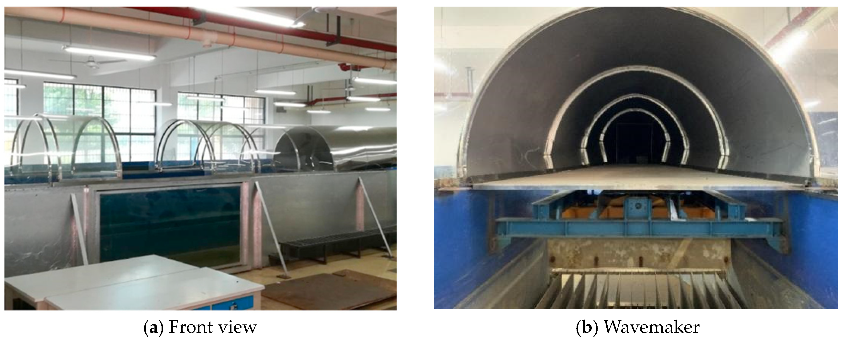
The dimensions of the flume are 14.65 m × 5.9 m × 1.8 m. The middle of the flume’s front channel is employed for testing. To facilitate observation, a glass window with dimensions of 2.7 m × 1.3 m is designed on the front wall of the flume, as shown in
Figure 1a. At the two ends of the flume, the outer and inner diameter are 5.9 m and 2.4 m, respectively. The wavemaker is installed at the flume’s right extremity, as seen in
Figure 1b. Powered by a robust 2 kW induction motor, this wavemaker can generate regular waves of up to 0.3 m in height and wave periods in the range of 0.5 to 4 s. It is also capable of generating irregular waves characterized by a variety of wave spectra. The water in the flume is driven by two axial pumps placed in the real channel of the flume to generate ‘tidal current’, as depicted in
Figure 1c. The two axial pumps are rated at 10 kW and 15 kW, separately. Consequently, the ‘tidal current’ velocity in the flume is adjustable, ranging from 0.1 to 2.0 m/s, by changing the pump’s rotational speed.
Figure 1d shows the sensor for measuring wave height in the experiment. It consists of a measuring rod, a signal processor, and a data transmission interface. To bolster precision and stability, the measuring rod is ingeniously crafted as a dual-rod structure to avoid deformation. In the measurement process, the metal measuring rod is inserted into the water to form a cylindrical capacitor, of which the capacitance fluctuates correspondingly to the oscillations of water levels. Then, the wave height can be derived from the value of the measured capacitance. The wave height meter is placed at the distance of 1D in front of the model pile to monitor the real-time wave height in front of the pile.
To facilitate this study, a sand pool was built on the floor of the testing section of the flume. The sand pool’s dimensions measured 3.8 m in length, 1.35 m in width, and 0.3 m in depth. The sand in the sand pool was standard quartz sand, characterized by a D50 of 0.64 mm. As carried out in [
25], carefully screening and cleaning the quartz sand in the pool was essential to ensure the reliability of the study.
To emulate the vibrations experienced by the monopile foundation of an operational OWT, a specialized shaker was purposefully designed. It is shown in
Figure 2.
As depicted in
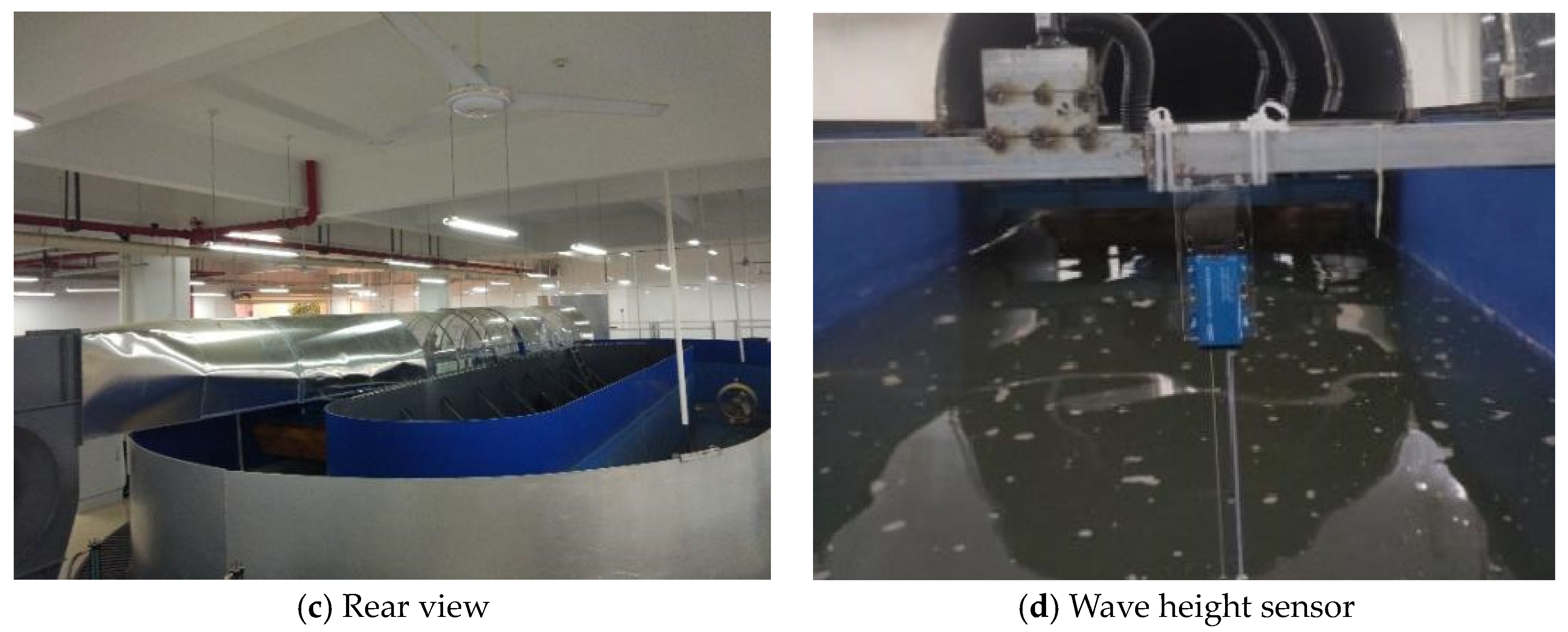
Figure 2a, the shaker comprises a DC motor integrated with a custom-designed cam mechanism. During testing, the vibration frequency of the shaker can be readily regulated by modulating the DC motor’s rotational speed. The vibration amplitude of the monopile can be conveniently adjusted by modifying the cam mechanism’s eccentric distance. As shown in
Figure 2b, a 2 m long hollow plexiglass pipe with an outer diameter and inner diameter of 100 mm and 80 mm, respectively, was used in the experiment to illustrate the monopile foundation of the OWTs. The pipe will be placed in the middle of the sand pit for the experimental simulation and firmly fixed to the floor of the sink by means of an aid clamp installed in the sand pit. During the test, the shaker was positioned atop a platform, elevated to a height of 1.3 m above the ‘mudline’ (i.e., the floor of the flume).
As illustrated in
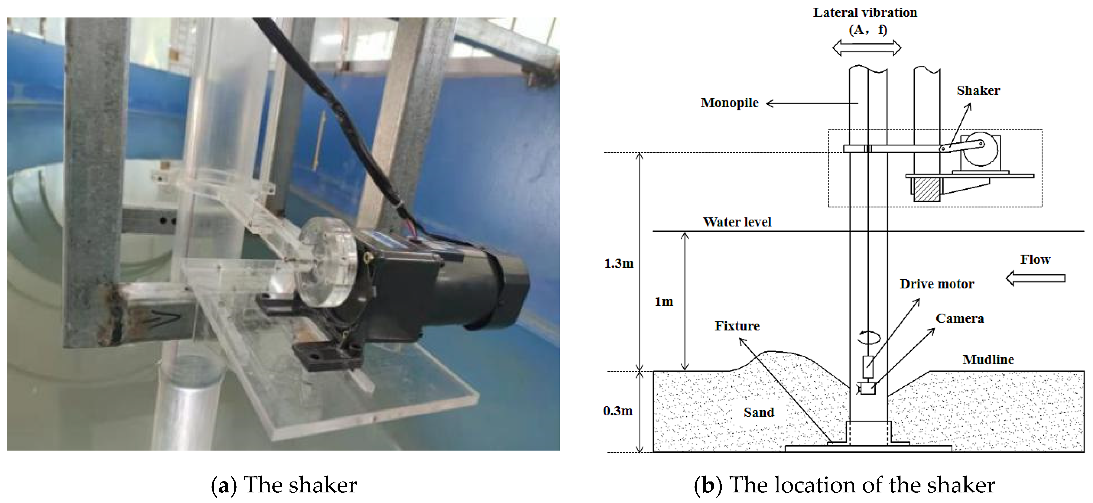
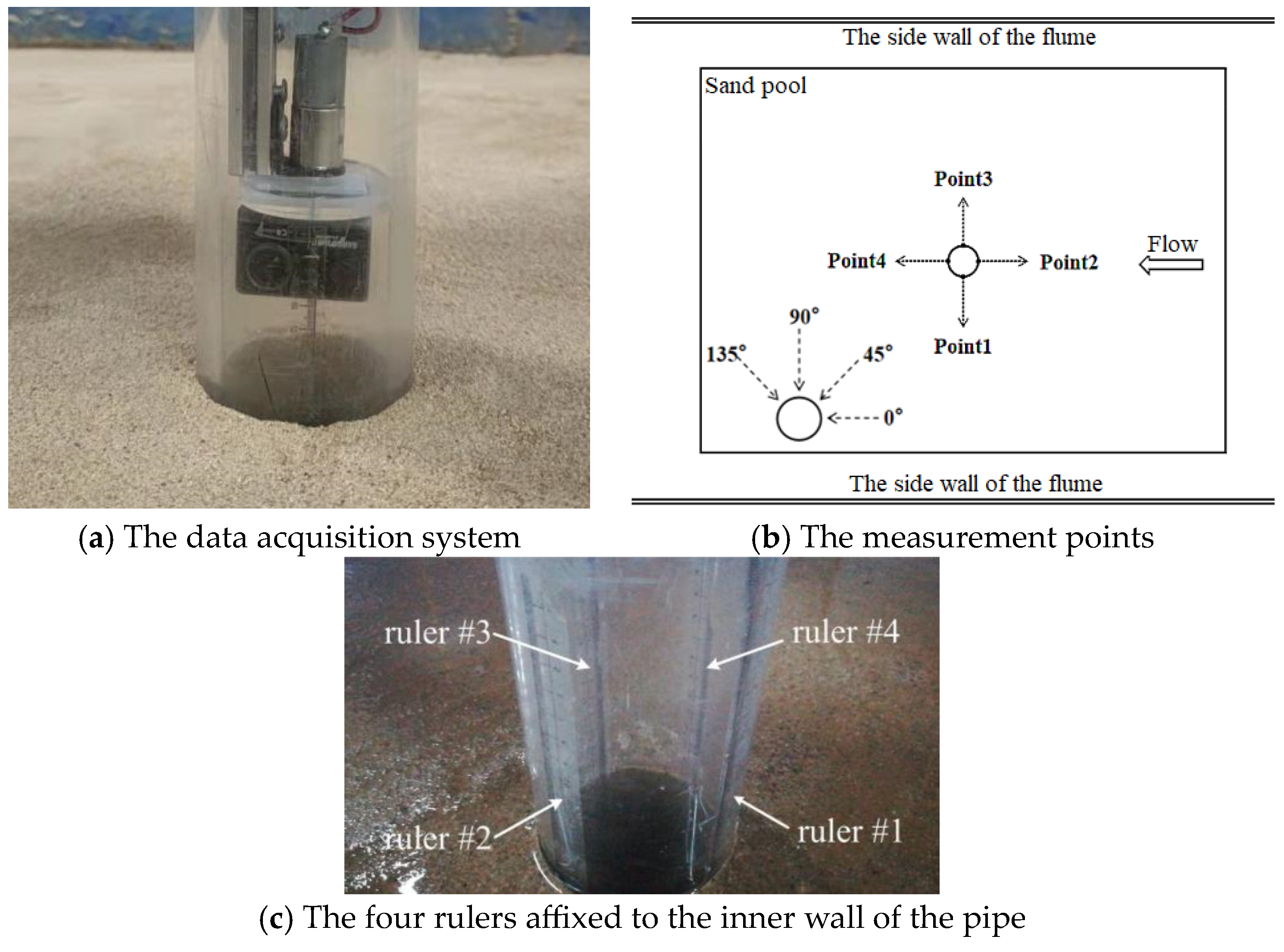
Figure 3, the data acquisition system utilized in this study comprises several components: a camera, a drive motor, four rulers securely affixed to the pipe’s inner wall, and a comprehensive lighting and power setup. Among the four rulers, ruler #1 and ruler #3 are employed to measure the scour pits ahead and behind the monopile foundation, respectively, and ruler #2 and ruler #4 are employed to measure the scour pits on the two sides of the monopile foundation. Throughout the test, the drive motor orchestrates the gradual rotation of the camera, capturing images of the sand bed encircling the monopile. Such a procedure facilitates real-time monitoring of the formation and development of the scour pits. The drive motor has a rated rotational speed of 5 rpm. However, it is adjustable. The camera provides close observations from all circumferential directions, supplemented by the four rulers on the pipe’s inner wall, ensuring precise and dependable measurements of the scour pits.
Considering that scour pits in different circumferential directions of the monopile may evolve at varying rates [
18], this study will measure the scour pits’ depths at four distinct positions encircling the monopile, as indicated in
Figure 3b. The designated measurement positions encompass the front (Point 2), rear (Point 4), and both sides (Points 1 and 3) of the monopile. Such a measurement strategy will ensure a reliable assessment of monopile scour.
Herein, it is important to highlight that, in this study, standard quartz sand was employed to replicate seabed conditions. It is crucial to recognize that this material differs from authentic seabed substances in various physical aspects. Consequently, there may be some variation in the measured data compared to the observations from actual offshore wind farms. However, it is essential to note that such differences do not compromise the understanding of the impact of tidal currents, waves, and monopile vibration on seabed erosion. This is because the use of different materials may influence the measured data, but it does not alter the fundamental knowledge of how tidal currents, waves, and pile vibration contribute to seabed erosion.
3. Testing Matrix
The experimental study reported in this paper was carried out through performing scour tests in two distinct sets of scenarios. The first set was designed to study the impact of monopile vibration direction on monopile scour under different tidal current and pile vibration conditions. The second was devised to delve into the impacts of various types of waves, in conjunction with in-line monopile vibration and tidal current, on the scour around the monopile. The testing matrix is outlined in
Table 1. Throughout the tests, the OWT foundation was represented by a 2 m long plexiglass pipe. The outer diameter and the thickness of the pipe were 100 mm and 10 mm, respectively. The water depth in the flume was constantly maintained at 1 m, the ‘tidal current’ velocity was consistently maintained at 0.22 m/s, and the tests in all scenarios persisted for a duration of 5 h, ensuring a uniform and reliable basis for meaningful comparisons. According to the Froude similarity, a 100 mm diameter pipe, a water velocity of 0.22 m/s, and a 1 m water depth in the tests correspond to a 4.5 m diameter monopile foundation, a tidal velocity of 1.5 m/s, and a 45 m water depth in real life. This is a typical OWT deployment scenario in the current offshore wind practice [
24].
In
Table 1, the test scenarios are denoted by distinct scenario codes, in which ‘A’ and ‘f’, respectively, represent the amplitude and frequency of pile vibration. For example, the code ‘A5f0.5′ signifies a scenario in which the pile vibration amplitude and vibration frequency are 5 mm and 0.5 Hz, respectively. In the Stage II tests, H/L denotes the ratio of water depth to wavelength. For example, ‘H/L2.701′ refers to a scenario in which the water-depth-to-wavelength ratio is 2.701 and the corresponding wave period is 0.5 s. The letter ‘V’ in the scenario codes indicates the introduction of monopile vibration. The absence of the letter ‘V’ in the scenario code means that there is no pile vibration in the test.
In accordance with the Froude similarity rule, the adoption of a 100 mm diameter pipe, a flow velocity of 0.22 m/s, and a water depth of 1 m during the tests corresponds to a scaled representation of a 4.5 m diameter monopile, a tidal current velocity of 1.5 m/s, and a water depth of 45 m in real-world application [
18]. This configuration mirrors a common OWT deployment scenario, aligned with prevailing practices within the current offshore wind industry. In addition, adhering to the guidelines outlined in [
25] regarding the maximum permissible top deflection of the wind turbine tower, the utmost admissible deflection for the pipe at the shaker position (located at 1.3 m above the flume floor) can be up to 16 mm. Therefore, two pipe vibration amplitudes, 5 mm and 10 mm, were taken into account during testing.
Taking into account the potential disparity between the direction of pile vibration and that of tidal currents owing to the intricate interplay of wind and wave dynamics in offshore wind farms, the Stage I tests considered four distinct lateral vibration directions, i.e., 0°, 45°, 90°, and 135°, relative to the tidal current direction, as illustrated in
Figure 3b, to scrutinize the effects of pile vibration direction on scour.
Finally, it is necessary to note that, due to the observed accelerated formation of scour pits in the initial one hour, followed by a more gradual progression in subsequent hours, the scour depth was measured once every 10 min during the initial one hour and then once every 30 min thereafter. The duration of each test was five hours in total.
4. Impact of Pile Vibration Direction on Scour
In the Stage I study that only examined the combined impacts of tidal currents and pile vibration on scour, the progression of scour pits at four measurement points, i.e., points 1, 2, 3, and 4 in
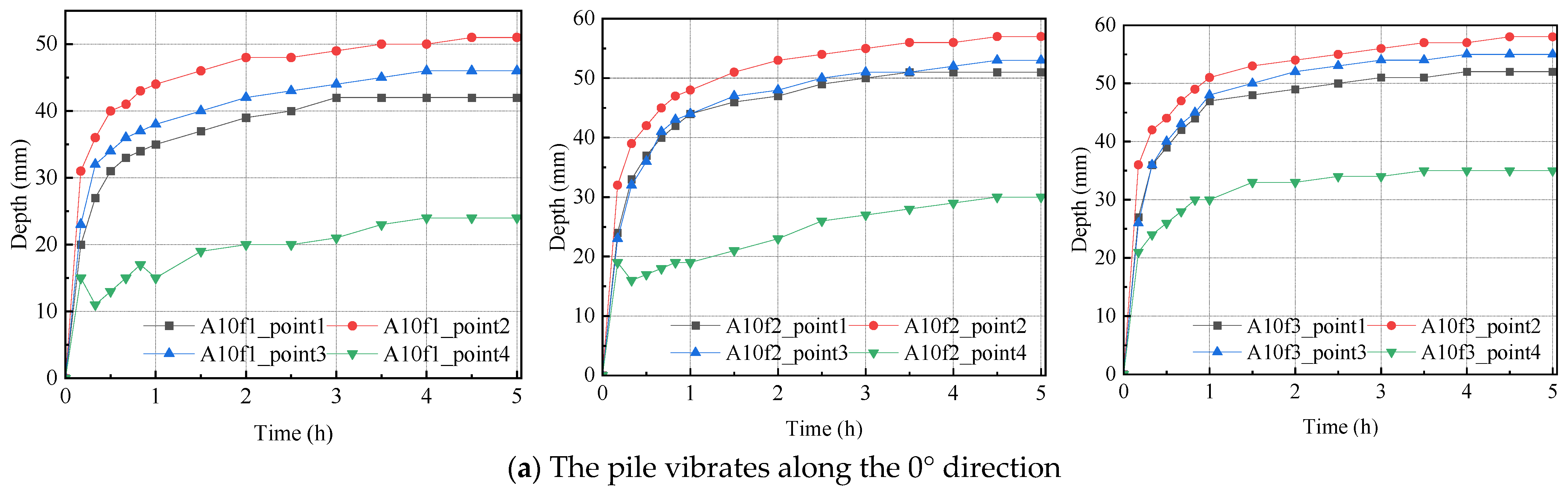
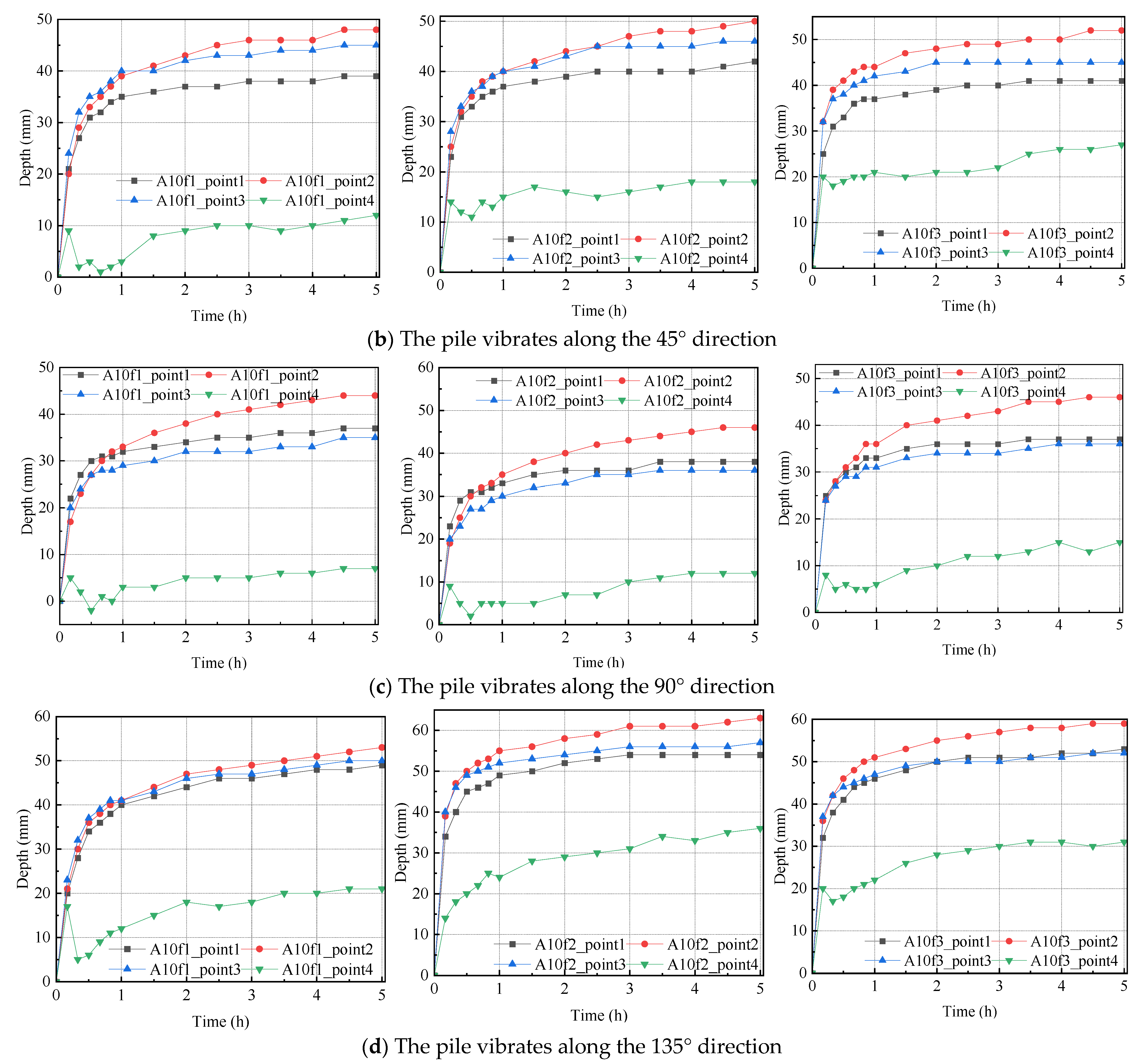
Figure 3b, was investigated under the condition when the pile was controlled to vibrate along different directions with respect to the inflow direction. All scour depth measurement results obtained during the experiment are visually presented in
Figure 4. Herein, it is worth noting that only those scenarios where the pile vibration amplitude is 10 mm are considered in the investigation. This specific choice stems from the discovery that high-amplitude vibrations of the monopile can trigger the convective motion of soil particles. Consequently, these soil particles become less likely to settle down and are more susceptible to being taken away by water flow [
20]. This, in turn, exacerbates pile scour and thereby benefits the investigation of the impact of vibration direction on scour.
From the scour depth results shown in
Figure 4, it is seen that, despite the tidal current and pile vibration conditions, the scour pits at the four measurement points exhibit rapid development during the initial period. Subsequently, the growth rate of the scour pits gradually tapers off, eventually reaching a point of saturation when the test is completed. This phenomenon arises due to the accumulation of water within the scour pits, which introduces an additional damping effect that mitigates the direct impact of the water flow on the sand grains atop the scour pit surfaces. Moreover, as the scour depth deepens, the volume of water within the pits increases. This leads to increased water damping, resulting in a diminished impact of water flow on the sand grains residing on the pit surfaces. When the scour pits become sufficiently deep, the water within the pits serves as an effective buffer, which can entirely prevent any additional development of scour pits. At this point, the scour depth stabilizes, and a state of saturation is attained, indicating that further development of the scour pits will be completely halted. In addition, a transient reduction in the scour depth behind the monopile observed in [
18] is also evident in
Figure 4. Since the reason for this phenomenon has been clearly explained in [
18], the explanation will not be repeated here. Of particular interest is the comparative analysis of the measurement results presented in
Figure 4a–d, revealing a noteworthy finding, i.e., the vibration direction of the OWT monopile foundation also exerts a substantial impact on the scour. Specifically, irrespective of the monopile’s vibration frequency and data measurement positions, it is evident that the most pronounced scouring mostly transpires when the monopile undergoes vibrations along the 135° direction relative to the inflow direction, while the mildest scouring mostly occurs when the pile vibrates along the 90° direction with respect to the inflow direction. The difference observed in the two scenarios can likely be attributed to the distinct interaction between the water stream and pile vibration. In the first scenario (i.e., vibrate along the 135° direction), the more forceful collision between the pile surface and water flow induces increased turbulence in the water flow, hindering the settling of sand particles and making them more prone to being carried away by the water flow. Conversely, in the second scenario, when the pile vibrates along the 90° direction relative to the inflow direction, the interaction between the pile surface and water stream is comparatively weaker, thereby leading to a milder scour around the pile foundation.
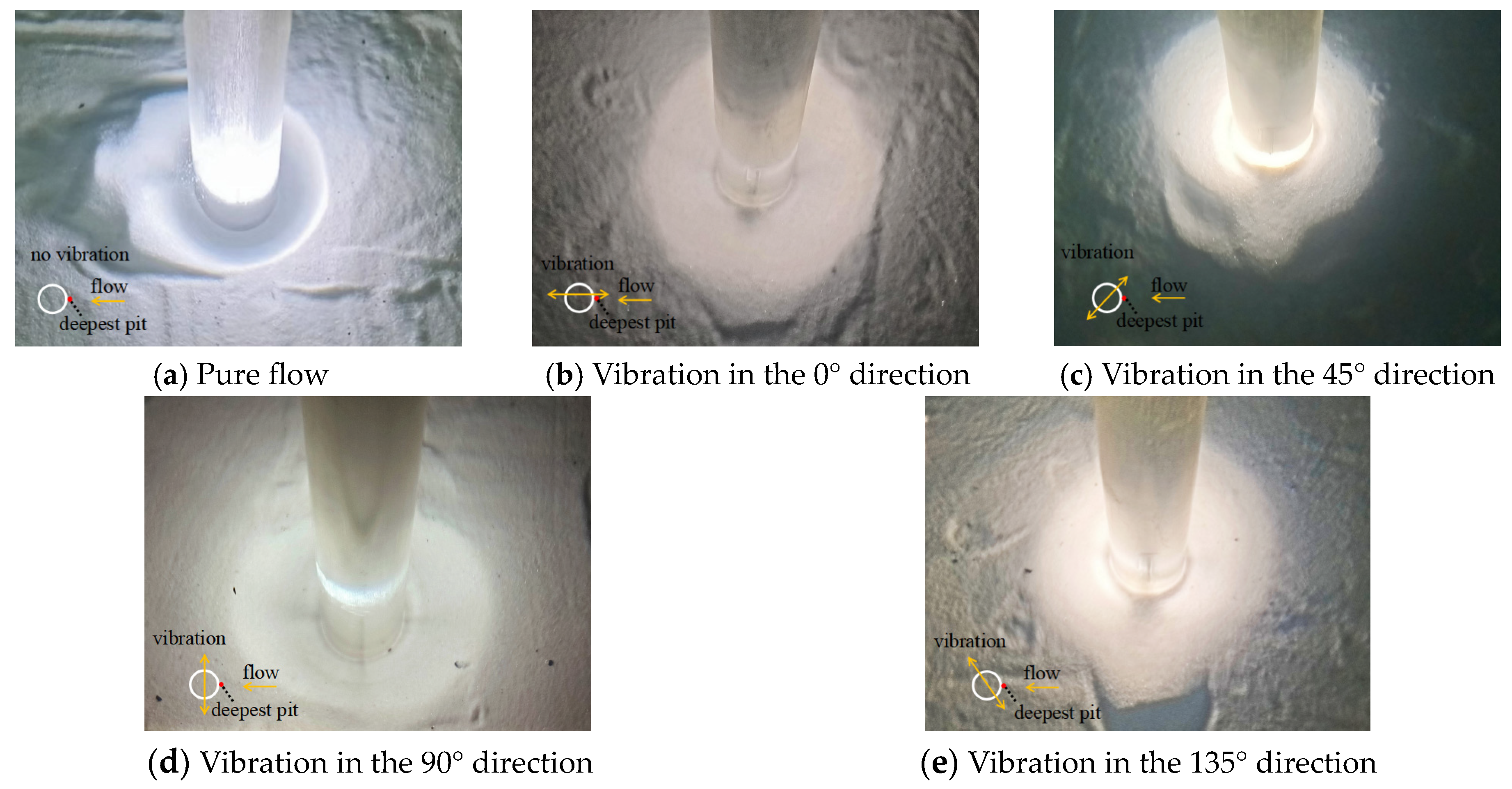
Furthermore, in the experimental study, special attention has also been given to the influence of the pile vibration direction on the morphology of scour pits. Some scour pits observed at the end of testing in scenario ‘A10f2′ are illustrated in
Figure 5.
Figure 5 indicates that the application of pile vibration also exerts a great impact on the morphology of the scour pits. This effect extends the boundaries of the scour pits in all circumferential directions and is not solely limited to the direction of pile vibration. This phenomenon arises from the disruption to the flow caused by the pile vibration, leading to a redistribution of vortex strength across all directions encircling the monopile. Consequently, the growth of scour pits in all circumferential directions is boosted when lateral vibration is applied to the monopile irrespective of the direction of vibration.
Additionally, a phenomenon different from what has been found in previous research is observed in the results shown in
Figure 4 and
Figure 5. In previous studies [
25], the deepest scour pits were often found appearing on the two sides of the monopile where horseshoe vortices occurred. However,
Figure 4 and
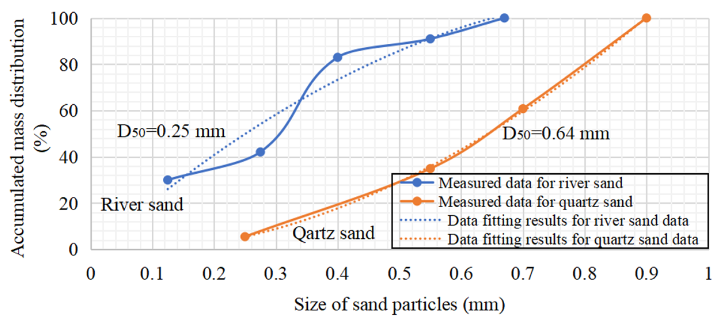
Figure 5 illustrate that, regardless of the experimental conditions, the deepest scour pit always emerges in front of the monopile. This is mainly due to the utilization of quartz sand in this study, whereas river sand was used in previous studies. As indicated in
Figure 6, river sand has a D50 of 0.25 mm, while quartz sand has a D50 of 0.67 mm. It is well known that larger sand grains exhibit reduced inter-grain friction. Influenced by this, during the formation of scour pits on the two sides of the monopile, the quartz sand grains accumulated behind the pile by the lee-wake vortices could more easily slide back into the scour pits on the two sides of the monopile. Consequently, when using quartz sand as the experimental material, the deepest scour pit often appears in front of the pile rather than on the two sides of the monopile.
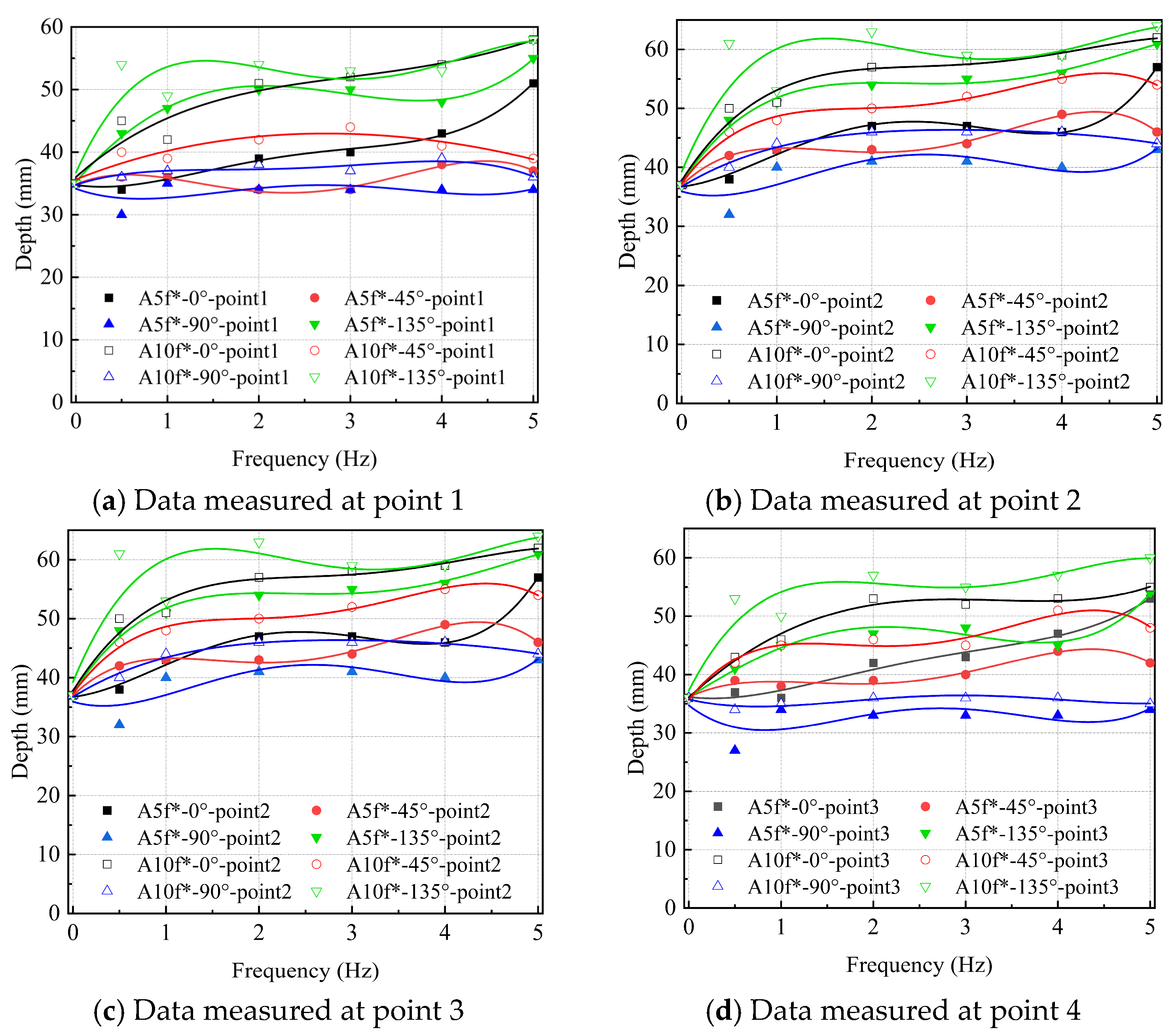
To delve into the combined influence of the monopile vibration direction, amplitude, and frequency on the scour surrounding the OWT monopile foundation, the experiments were iterated with two distinct pile vibration amplitudes, specifically, 5 mm and 10 mm. The resulting data from these tests are visually presented in
Figure 7.
In
Figure 7, it is found that stronger monopile vibration, characterized by larger vibration amplitudes, boosts the scour pits’ development regardless of the pit locations and the frequency of pile vibration. Moreover, in contrast to the frequency of pile vibration, it is evident that pile vibration amplitude exerts a more pronounced influence on scour. Such phenomena align with the earlier observations documented in [
20]. Notably, while prior research has highlighted these interesting trends, a comprehensive exploration of the combined effects of the pile vibration direction, vibration amplitude, and vibration frequency on scour has remained uncharted territory. From the testing results presented in
Figure 7, it is inferred that, within the intricate interplay of pile vibration amplitude, frequency, and direction, the influence of the pile vibration direction on scour is equally prominent and foreseeable as that exerted by the vibration amplitude. Moreover, the pile vibration direction contributes significantly to the variations in the equilibrium depth of scour pits. As mentioned earlier, the most substantial scour occurs when the monopile vibrates along the 135° direction with respect to the inflow direction. In contrast, the pile vibration has the mildest influence on scour when the pile vibrates along the 90° direction relative to the inflow direction. The pile vibration frequency also introduces alterations in the scour at the four measurement points. However, unlike the foreseeable effects of the pile vibration amplitude and direction, the influence of the pile vibration frequency on scour is less predictable, although it is noteworthy that the increasing frequency in the low frequency range in
Figure 7 appears to expedite the progression of scour pits. This is because, in principle, the frequency of pile vibrations can interfere with the natural transport of sediment in the water, and high-frequency vibrations may disturb the equilibrium, making it challenging for sediments to settle and leading to their removal by the water flow. However, the actual interaction between the pile and the surrounding water flow is more intricate. For instance, when the frequency of pile vibrations aligns with the resonant frequency of the sediment, it can result in concentrated erosion and unpredictable scour patterns. Nevertheless, predicting the resonant frequency of sediment in practical applications proves to be challenging.
5. Impacts of Different Types of Waves on Seabed Erosion
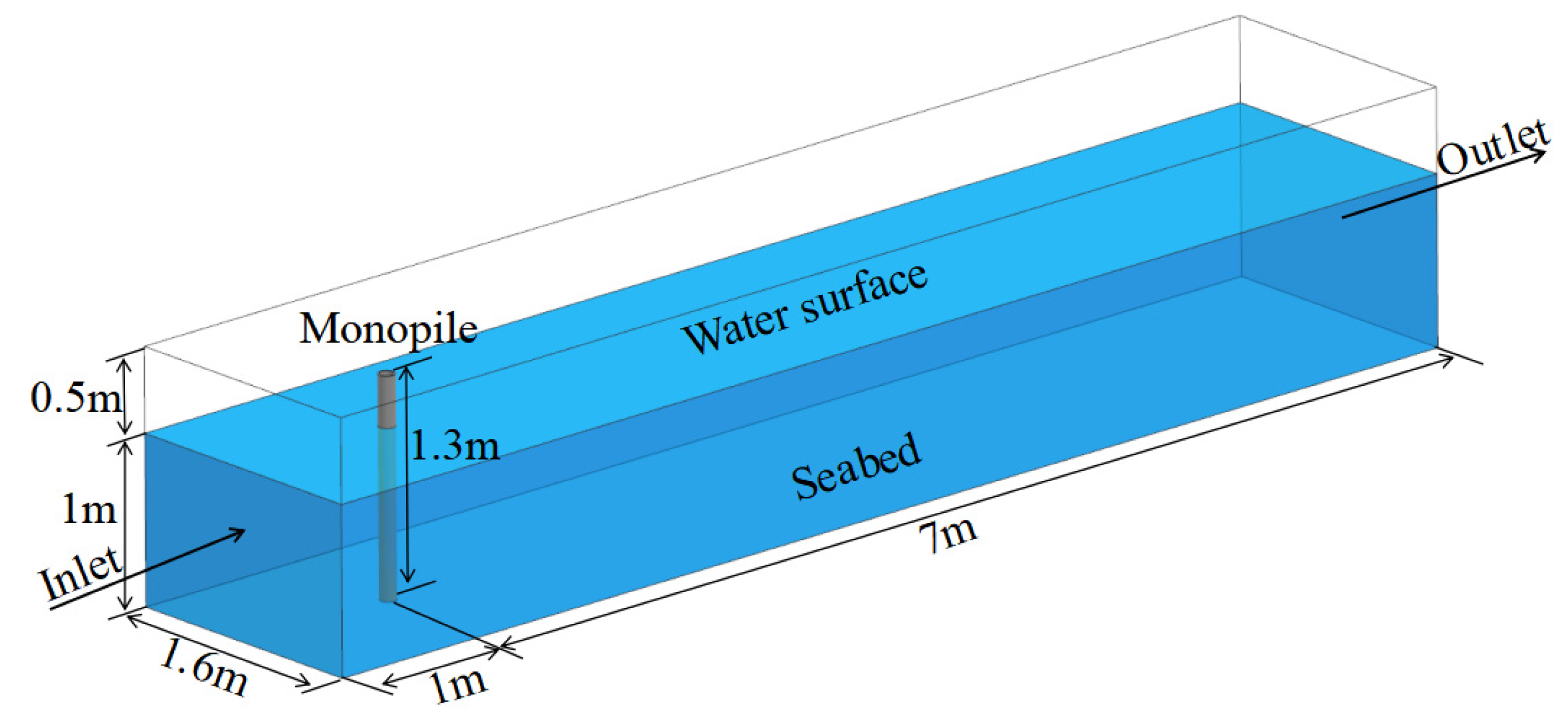
Deep water waves and shallow water waves represent distinct categories of wave phenomena that exhibit contrasting behaviors in the water they propagate through. Within the realm of wave theory, these two wave classifications diverge based on the dimensionless ratio of water depth, H, to wavelength, L, denoted as H/L. Shallow water waves are characterized by an H/L ratio of less than 1/20. Deep water waves manifest when the H/L ratio surpasses 1/2. In the intermediary range, delineated by H/L ratios ranging between 1/20 and 1/2, waves are classified as intermediate. Since deep water waves demonstrate substantial energy dispersion along the water depth direction and shallow water waves exhibit minimal energy dispersion along the water depth direction, in theory, they should have different influences on the movement of seabed sediments. To illustrate the contrasting impacts of these two categories of waves on the seabed, a numerical model was established, which is depicted in
Figure 8. The computational domain of the model is 8 m long, 1.6 m wide, and 1.5 m high. The monopile is situated downstream and positioned at a distance of 1 m from the inlet, while the water depth is fixed at 1 m. The boundary conditions on the seabed and monopile were defined as no-slip boundaries with smooth wall roughness. The water surface was defined as a free-slip boundary condition to simulate the less frictional effect of the free sea surface. At the inlet, the boundary condition was defined as the velocity boundary with a tidal current velocity of 0.22 m/s. The outlet was set as open boundaries with zero relative pressure, which allowed the water to freely flow out of the domain. The two side walls of the computational domain were designated as symmetry boundaries. In the simulation conducted in this study, the RNG k-ε turbulence model was employed. The reason for using such a model is that, compared to the conventional k-ε model, the turbulence model considers both the flow and its spatial position, which allows the model to effectively handle flows with substantial streamline curvature. This makes the RNG k-ε turbulence model particularly well suited to simulate water waves. Following consistency checks, the whole computational domain is meshed using 552,042 elements to ensure the accuracy of the calculation results.
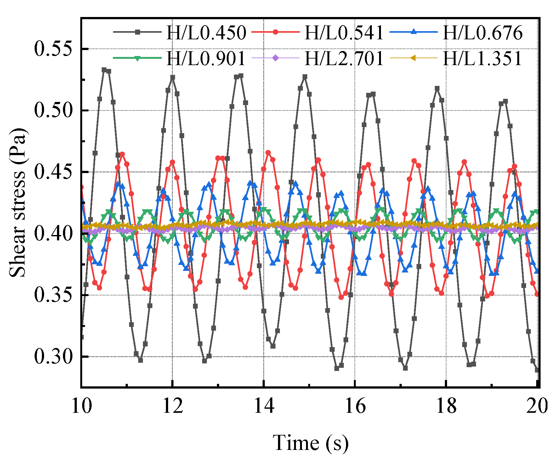
Then, waves of different periods were generated on the water surface by using the popular wavemaker velocity boundary condition based on the potential flow theory [
26], and the wave-induced shear stress exerted on the surface of the seabed was calculated under various wave conditions. The shear stress calculation results obtained in different H/L ratio scenarios are shown in
Figure 9.
In
Figure 9, it is clearly seen that waves characterized by different H/L values have distinctly different impacts on the shear stress on the seabed surface near the monopile. Notably, waves with smaller H/L values elicit greater shear stress on the seabed surface, implying that shallow water waves have the potential to wield a more pronounced influence on monopile scour compared to deep water waves.
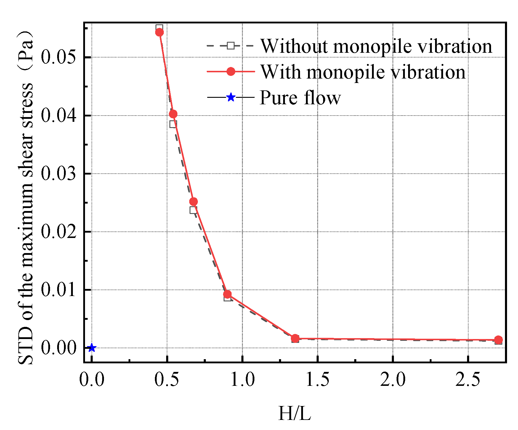
Subsequently, the monopile vibration’s impact on seabed erosion around the monopile is studied under different wave conditions by utilizing the numerical model. As shear stress exhibits temporal fluctuations over time, its intensity is denoted using the standard deviation (STD) of its fluctuation.
Figure 10 portrays the STD values of the maximum shear stress observed, respectively, under six distinct wave conditions before and after introducing the monopile vibration along the inflow direction (i.e., 0°). In the figure, the STD value of the maximum seabed surface shear stress obtained under the ‘pure flow’ condition is also plotted to facilitate a comparison.
Analyzing the computational results shown in
Figure 10 reveals that the introduction of monopile vibration tends to augment the shear stress on the seabed near the monopile regardless of the wave conditions. In the meantime, the results in
Figure 10 demonstrate, once again, that a reduced H/L ratio corresponds to elevated shear stress levels around the monopile. This suggests that the OWT monopile foundation could face more challenges when situated in shallow water waves.
6. The Impacts of Different Types of Waves on the Scour around the Monopile Foundation
In order to verify the influences of waves and pile vibration indicated by the calculation results in
Section 5, various experimental tests were conducted in the flume illustrated in
Figure 1 and
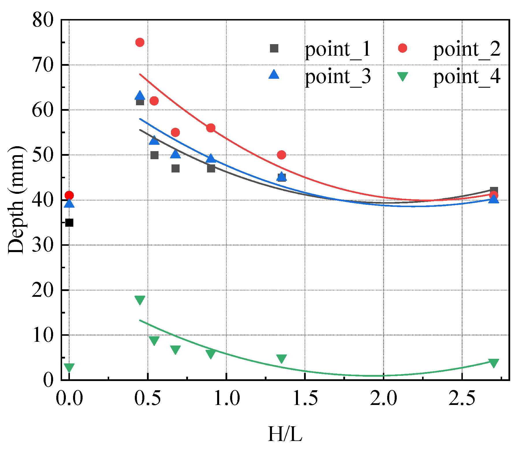
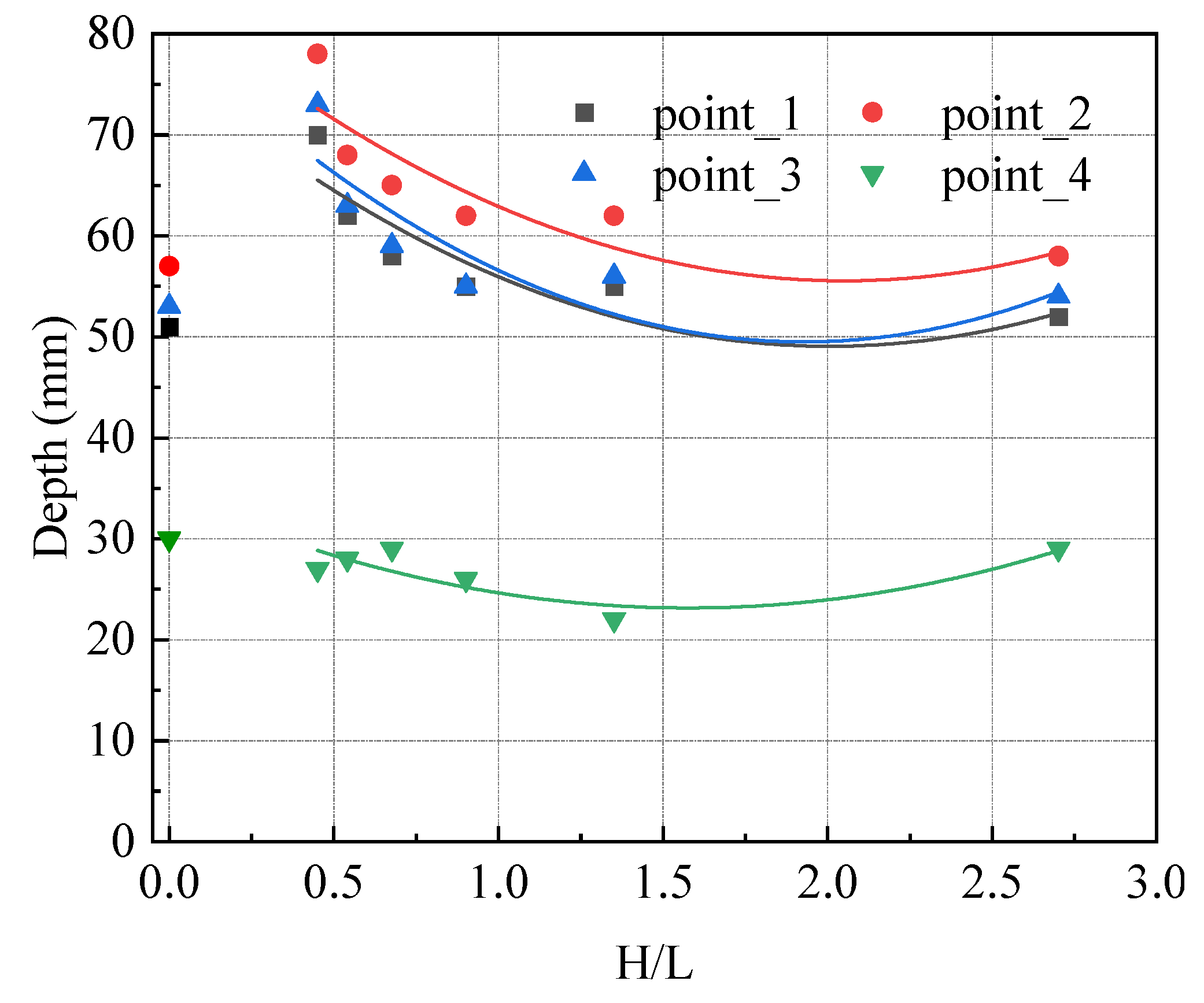
Figure 2. These tests were first undertaken under varying ‘wave and flow’ conditions indicated by the following scenario codes: H/L2.701, H/L1.351, H/L0.901, H/L0.676, H/L0.541, and H/L0.45. In each scenario, the scour depth at each measurement point was measured after 5 h of testing. The results were measured and are depicted in
Figure 11. In the figure, the maximum scour depth values measured under the ‘pure flow’ condition, placed at H/L = 0, are also plotted to highlight the impact of waves on scour.
In
Figure 11, it is found that regardless of the specific types of waves denoted by the H/L ratios, waves indeed expedite the development of scour pits at all four designated measurement points. Intriguingly, this effect intensifies as the H/L ratio decreases. In simpler terms, the influence of waves on scour becomes more pronounced as the H/L ratio decreases. This observation is in good agreement with the results shown in
Figure 9 and
Figure 10. These findings indicate that, when compared to deep water waves (characterized by H/L > 1/2), shallow water waves (characterized by H/L < 1/20) exert a more substantial influence on seabed erosion. Consequently, they pose a greater threat to the reliability and safety of the fixed foundations of OWTs.
Furthermore, experimental tests were conducted under varying ‘wave, flow, and pile vibration’ conditions, denoted by the H/L2.701V, H/L1.351V, H/L0.901V, H/L0.676V, H/L0.541V, and H/L0.45V scenario codes, to investigate the intricate interplay of waves and pile vibration during the generation process of scour pits. In these tests, the pile was designated to vibrate along the inflow direction (i.e., 0°). The results of the scour depth measured at the four measurement points following 5 h of testing are shown in
Figure 12. Likewise, the scour depth values measured in the ‘A10f2′ scenario (one of the ‘flow and pile vibration’ scenarios) are also plotted for comparison. They are placed at H/L = 0.
After the pile vibration characterized by an amplitude of 10 mm and a frequency of 2 Hz is introduced, the scouring behaviors in all circumferential directions are enhanced, resulting in deeper scour pits occurring at all four measurement points.
In addition to the enhanced effect of pile vibration, the presence of waves further expedites the formation of scour pits at measurement points 1, 2, and 3.
Despite the boosting effect induced by the pile vibration, it is notable that the presence of waves appears to counteract the progression of the scour pit situated behind the monopile (i.e., at measurement point 4).
To more effectively highlight the aforementioned observations,
Table 2 presents the corresponding scour depth values across all scenarios.
Furthermore, to obtain a better understanding of the distinct impacts of various types of waves on scour and the intricate interplay between waves and pile vibration in intensifying scour, the scour depth measured from the four designated points in the ‘pure flow’ scenario is used as a benchmark to calculate the relative increases in scour depth in the other scenarios. The calculation results are shown in
Table 3.
When analyzing the data in
Table 3, it becomes evident that, while the deepest scour pit forms in front of the monopile (at point 2) and the shallowest scour pit occurs behind the monopile (at point 4), the presence of waves most significantly impacts the scour behind the monopile. Additionally, the magnitude of the waves’ influence is usually more pronounced when the H/L ratio is smaller, especially in the absence of pile vibration. This trend holds true for the outcomes observed at all four measurement points, with only a few exceptions.
Secondly, the introduction of pile vibration indeed strengthens the scour across all four measurement points, with a particularly noticeable enhancement at point 4 (behind the monopile). Nonetheless, the reduced values recorded at point 4 after introducing waves in the H/L2.701V, H/L1.351V, H/L0.901V, H/L0.676V, H/L0.541V, and H/L0.45V scenarios suggest that the waves counteract a little bit of the effect of pile vibration on the scour behind the monopile. This phenomenon arises from an intricate interplay of multiple factors, making it difficult to explain. It is not solely governed by the interactions between waves, pile vibration, and tidal currents, but it is also influenced by the horseshoe vortices on the two sides of the monopile and the lee-wake vortices behind the monopile.
Finally, it is discernible that in the interplay between the impacts of waves and pile vibration on scour, waves wield a dominant influence when the H/L ratio is small. Conversely, when the H/L ratio is large, the dominance shifts to pile vibration as the major influencing factor.


