1. Introduction
Growing environmental concerns have accelerated the shift in transportation from vehicles and buses to unmanned aerial vehicles (UAVs) and trains powered by electricity. Electrified mobility solutions, such as trams, significantly reduce emissions when compared to conventional powertrains. Many countries are increasingly adopting fully electrified trams as alternatives to traditional on-road public transport systems, owing to their eco-friendliness with efficient transportation capabilities.
A pure electric tram’s powertrain, consisting of an electric motor and a battery, resembles that of an electric vehicle. Due to its simple configuration and control strategies, it presents an accessible option for manufacturing and replacing other public transportation systems. However, to cover longer distances and higher altitudes, additional power sources are necessary. Two primary methods exist for supplying this additional power: (1) storing ample power at the start of operation and (2) regenerating power during operation.
In certain scenarios, a high-capacity battery can serve as a viable solution owing to its simplicity. However, it might have limitations for covering much longer distances or driving in more challenging conditions. The fuel cell hybrid system has emerged as a suitable alternative to address the limitations of high-capacity batteries while maintaining the advantage of zero emissions. Fuel cell hybrid trams can operate without a charged battery and store excess fuel cell power in an energy storage system (ESS). When it comes to mass increase, the fuel cell system holds the advantage of providing a long driving range compared to batteries [
1]. It turns out that the hybrid system in an electrified powertrain is more effective for operating commercial vehicles.
In the field of fuel cell hybrid systems, extensive research has been conducted on energy management systems (EMS) [
2,
3,
4]. These systems are categorized into two groups based on their properties: ‘offline control’ and ‘online control’ [
5]. These control methods operate in different environments, where the control algorithm determines actions. ‘Offline control’ deals with given data, allowing control output decisions to be made based on interactions with future states of the model. In both single-powered systems and various energy-sourced hybrid systems, this strategy has the advantage of being deterministic [
6,
7]. It consists of ‘rule-based’, ‘optimization-based algorithms’, and the ‘equivalent consumption minimization strategy (ECMS)’. These approaches offer a concise development process because ‘offline control’ aims to optimize within given conditions and clearly defined control modes.
In contrast, ‘online control’ is a practical method actively developed to address real-time management challenges and overcome the limitations of ‘offline control’ in terms of generalization. Since control decisions of ‘online control’ can be made without knowledge of future states, it is more adaptable to manage arbitrary conditions that were not previously considered. Model predictive control (MPC) and learning-based reinforcement methods fall under the ‘online control’ group. For instance, studies on speed profile estimation control combined with MPC and ECMS have demonstrated performance close to the global solution in real-time situations, as referenced in [
8,
9,
10].
According to the concepts outlined above, ‘online control’ appears more adaptable for real applications, but the ‘online control’ method has also shown instability and a heavy reliance on stochastic processes. This still renders ‘online control’ unsuitable for vehicle operation adaption. Despite ECMS-based adaptive control, combined with Markov chain model estimation [
11,
12] and locally updated control factors considering the states of railway vehicle hardware [
13,
14,
15], ‘offline control’ still faces challenges in energy management in unexpected cycles due to the difficulty of predicting future movement [
16].
On the other hand, for predefined repeated railway cycles, ‘offline control’ may become more practical for optimal energy distribution in a fuel cell hybrid system. This approach utilizes ECMS-based Pontryagin’s minimum principle (PMP) as an ‘online control’. As seen in the literature [
17], PMP optimization, obtaining control factors from a pre-calculated co-state table for every fixed route, can address these limitations. However, this process requires a complex algorithm to determine the optimal energy distribution at every step.
In contrast, we propose a map-based deterministic ECMS strategy for optimal energy distribution in hardware applications to guide control decisions, eliminating the need for constant recalculation mentioned in the previous paragraph. This method ensures a stable and error-free system. This aspect has been extensively studied in engine-based hybrid vehicles [
18,
19]; however, it is rarely conducted in fuel cell hybrid systems. To validate the proposed ECMS control process, we conducted a simulation using an Autonomie (REV15SP1), a vehicle system energy analysis software offered by Argonne National Laboratory, and examined its feasibility by comparing it to rule-based control optimized for a specific tram cycle.
The remainder of this paper is organized as follows:
Section 2 models the powertrain of the fuel cell hybrid tram manufactured by Hyundai Rotem.
Section 3 describes in detail the control strategies for energy distribution.
Section 4 and
Section 5 describe the simulation settings and results. Finally,
Section 6 presents the conclusions.
2. Fuel Cell Hybrid Tram Modeling
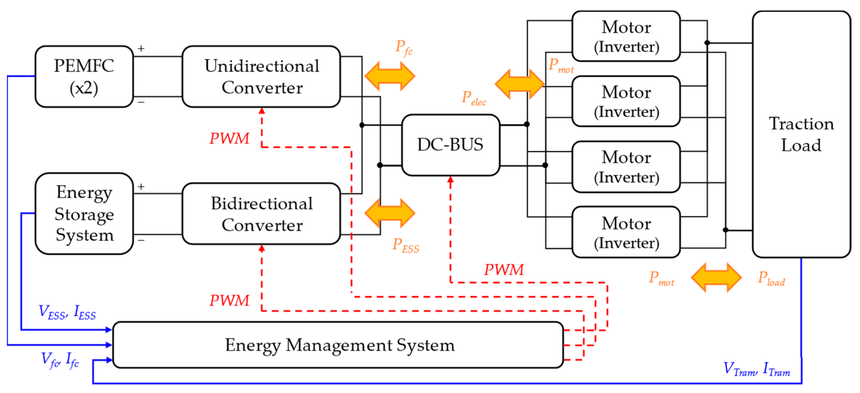
Fuel cell hybrid systems typically employ various topologies that determine how the fuel cell system (FCS), battery, and ultracapacitor (UC) are interconnected [
20,
21]. In this project, the tram model follows the ‘FCS + Battery hybridization’ topology, comprising two fuel cell stacks and a single ESS, as shown in
Figure 1.
In this model, the fuel cell stacks and the ESS supply electrical power to four motors either simultaneously or separately. To simplify the simulation process and concentrate on evaluating the energy distribution control, each component model is simulated based on energy exchange. The tram simulation model was constructed using mathematical equations and the properties of each component were defined in a pre-established map. The fundamental specifications of the fuel cell hybrid system, as published by Hyundai Rotem [
22], are listed in
Table 1.
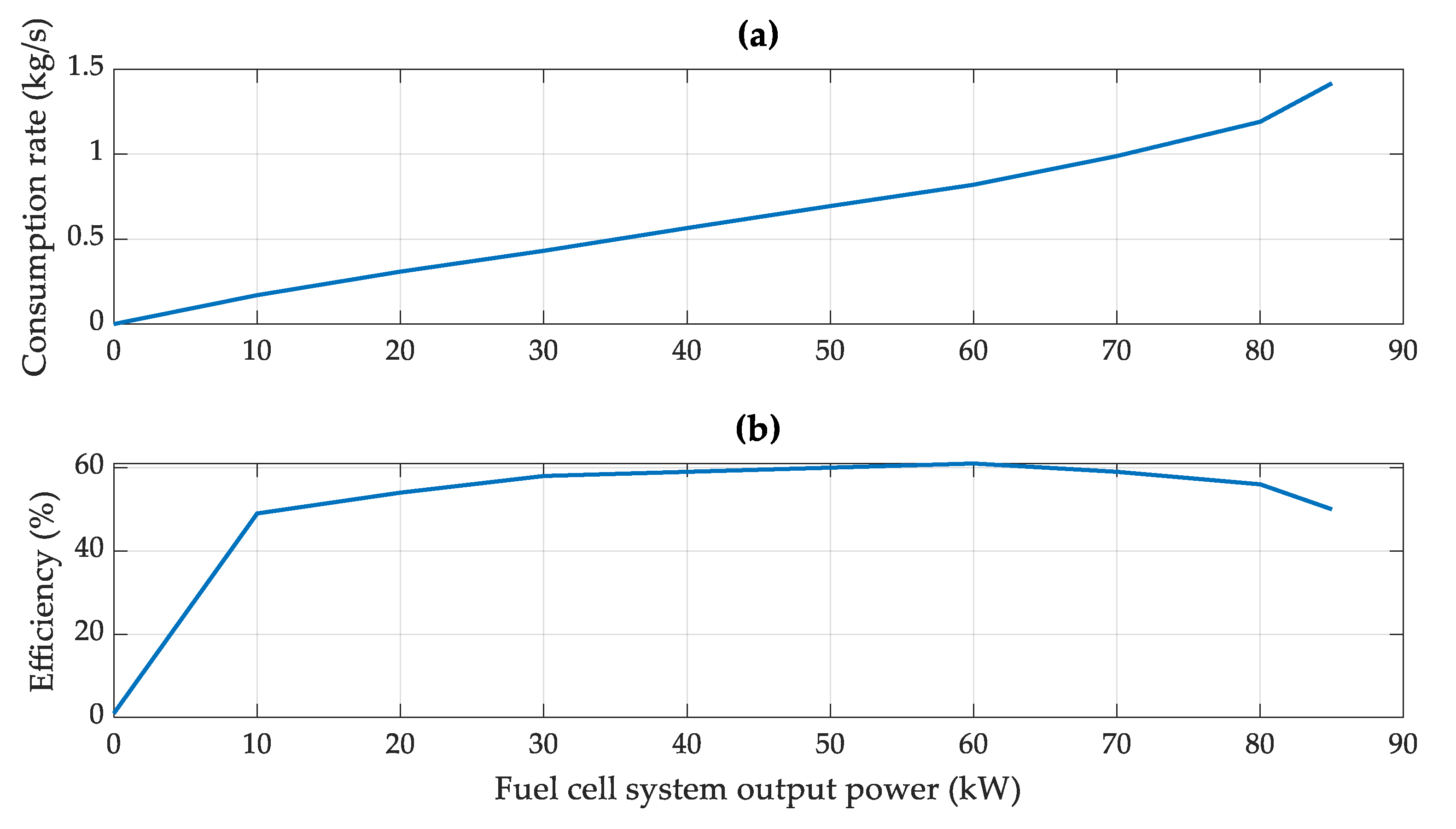
2.1. Fuel Cell System
The fuel cell system was designed to generate electric power in response to the controller’s energy distribution and the activation of several accessory devices essential for its operation, such as pumps, compressors, expanders, and radiators. A fuel cell stack simulation model was used to calculate the hydrogen fuel consumption rate. As shown in
Figure 2, this consumption rate is determined based on a function that considers both the output power and the system efficiency of the fuel cell stacks. It is important to note that while the consumption rate of hydrogen increases linearly with its output power, the efficiency of the fuel cell stack creates nonlinear convex curves.
2.2. Energy Storage System
The fuel cell hybrid tram’s ESS served as a supplementary energy source. Unlike the fuel cell stack, it not only draws electric power but also stores excess power and regenerated energy while the tram operates.
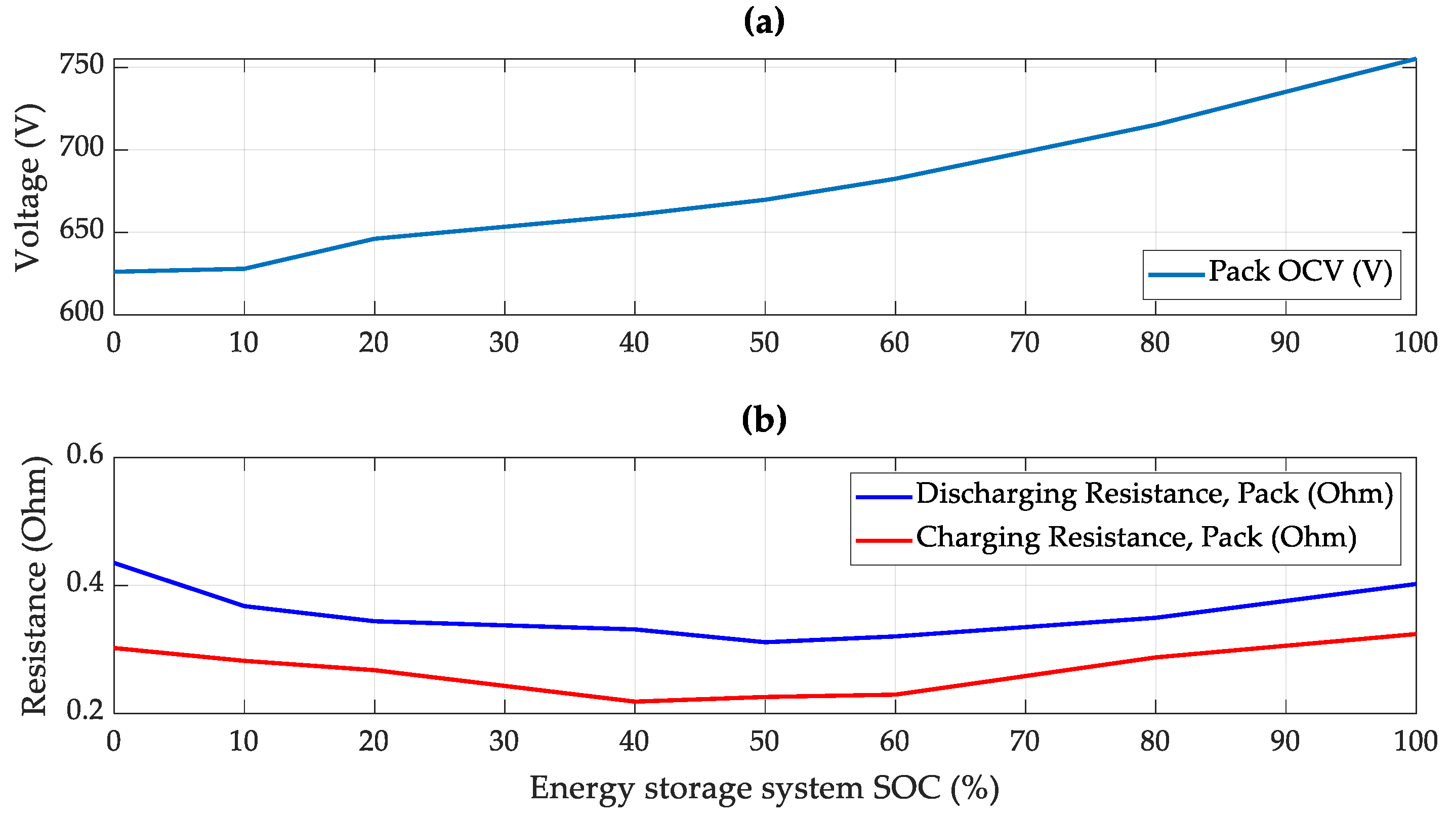
The ESS was modeled using an equivalent circuit model [
23], designed to simulate transient situations and provide a more accurate reflection of real-world driving conditions through its characteristics, as shown in
Figure 3. Its feasibility was enhanced by considering the internal resistance in relation to the system’s state of charge (SOC). Equations (1) and (2) outline the energy storage system’s governing equations:
In this equation, and represent the voltage of open-circuit and output, respectively, represents the internal resistance, represents the capacity, and represents the output current.
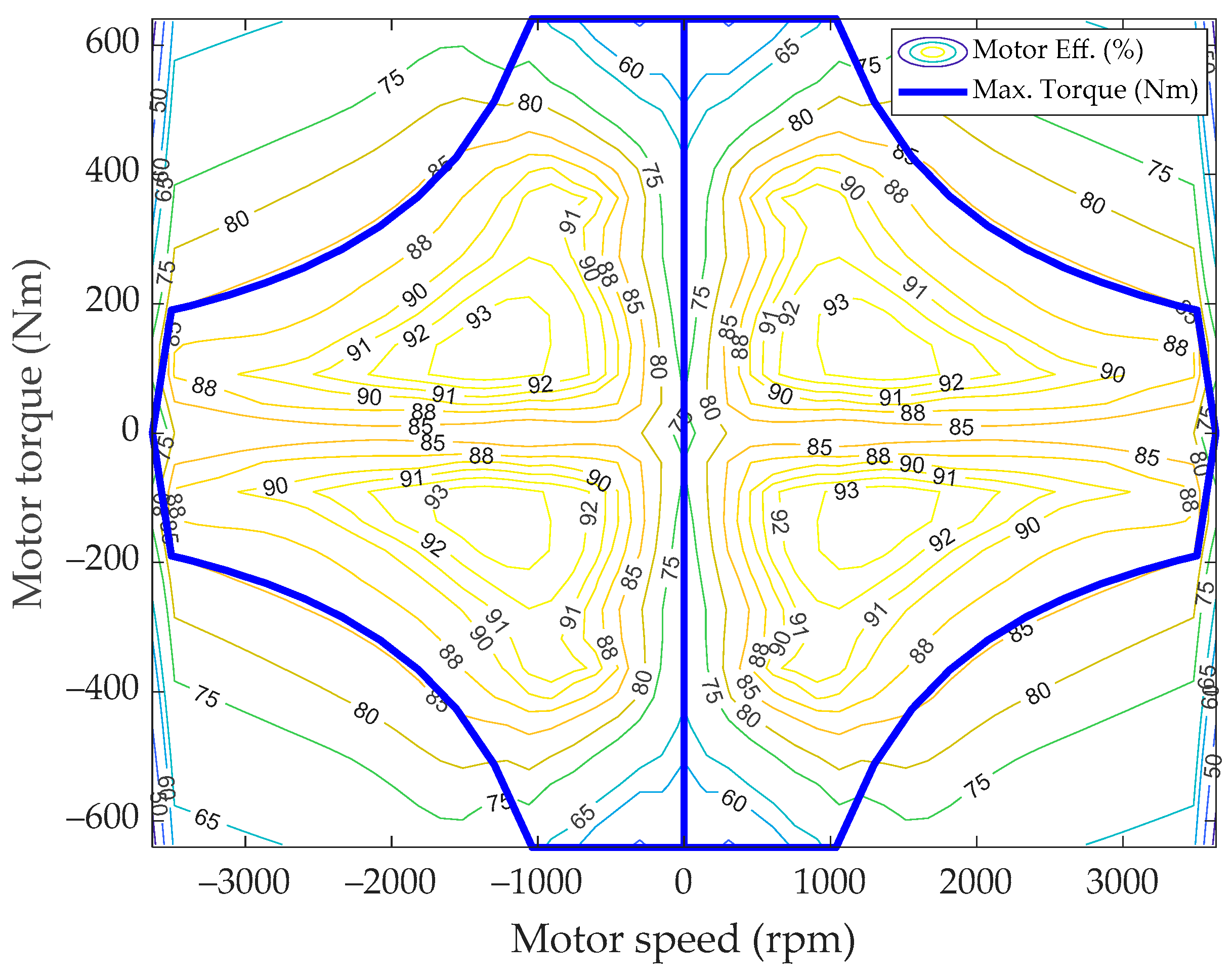
2.3. Electric Motor Modeling
The fuel cell hybrid tram is equipped with four 70 kW electric motors, with each motor paired with one of four wheels. Unlike passenger vehicles, they distribute all torque equally to each wheel. Each motor propels the tram using electrical power supplied by the fuel cell stacks and the ESS simultaneously or separately.
These electric motors were designed to convert electrical energy into mechanical energy and reverse it during regenerative braking. The efficiency of electric motors affects their output power, as shown in
Figure 4. The relationship between motor efficiency and output power is expressed by Equations (3) and (4) as follows:
where
represents the electric power,
represents the mechanical power, and
represents the efficiency of the electric motor.
2.4. Longitudinal Dynamic Modeling
A one-dimensional simulation model of the fuel cell hybrid tram dynamics assumes that the tram moves in a straight direction, with its speed directly linked to the driving force. As the speed increases, the required propulsion power also increases.
Simultaneously, the tram must overcome various disturbance forces, including aerodynamic and climbing resistances. Both types of resistance depend on the tram’s speed. The force exerted by the wheels of the tram is defined in Equations (5)–(7), which are consistent with those used in one-dimensional vehicle simulation models.
where
represents the density of air,
represents the equivalent frontal area of the vehicle,
represents the coefficient of drag,
denotes the vehicle’s linear speed,
represents the mass of the vehicle,
represents gravitational acceleration, and
represents the gradient or slope.
3. Energy Management System Optimization Control
When it comes to the fuel cell hybrid system, the controller is required to balance the consumption of hydrogen with the usage of electrical power from the ESS. The fuel cell hybrid tram that offers diminished fuel consumption, coupled with SOC management by balancing its fluctuation, is considered as an optimally controlled vehicle.
To achieve superior performance, it is essential to distribute the energy between two energy sources. In this study, two strategies were compared. The first is an empirically developed rule-based control strategy, and the second control strategy is an optimal control method based on the ECMS. The rule-based strategy defines energy distribution through various control parameters derived from vehicle specifications and optimized points through parametric studies, while the ECMS derives optimal control from the numerical method. The subsequent section analyzes these control strategies and compares their system efficiencies.
3.1. Rule-Based Control with Control Parameters
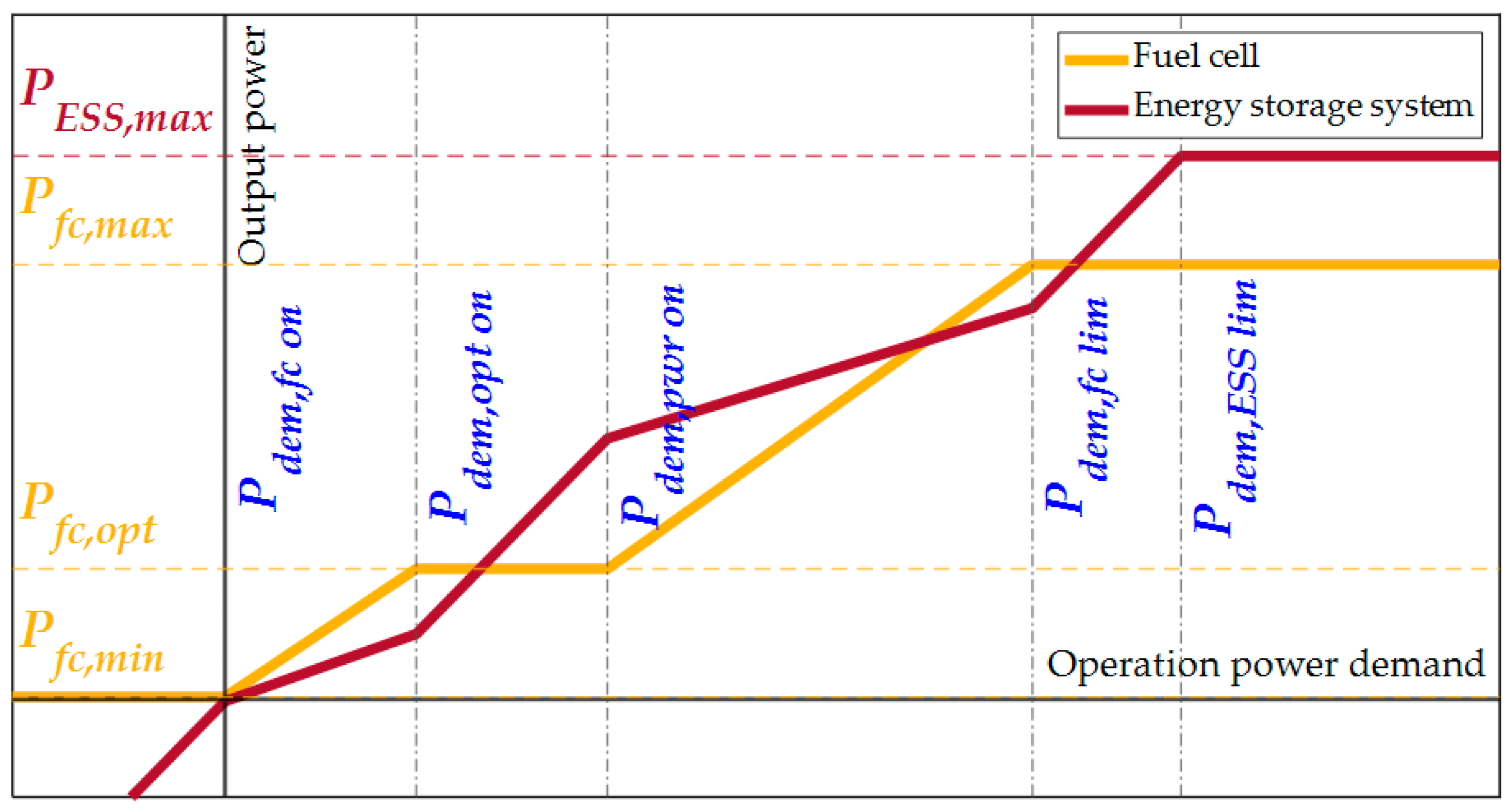
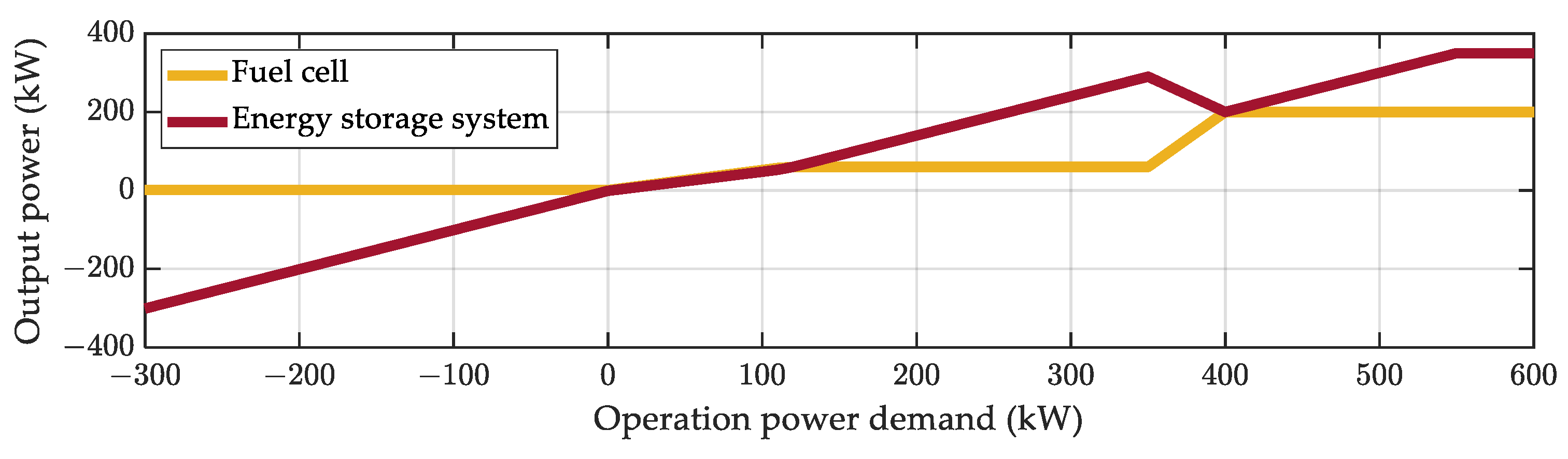
Rule-based control is an intuitive method to distribute power between the fuel cell stacks and the ESS in response to the total power demand.
Figure 5 shows this method, where the power from the fuel cell stacks is indicated by a yellow line and the power from the ESS is indicated by a red line. In this control strategy, several key points, referred to as the control parameters, are established to define the control concept. These parameters are divided into two categories. The first group is associated with the powertrain system specifications, such as minimum power (
Pfc,min), maximum efficiency power (
Pfc,opt), and maximum power (
Pfc,max) of the fuel cell system and maximum power (
PESS,max) of the ESS. The second set of parameters, we named the main control parameters, determines the control mode of the fuel cell hybrid system;
Pdem,fc on,
Pdem,opt on,
Pdem,pwr on,
Pdem,fc lim, and
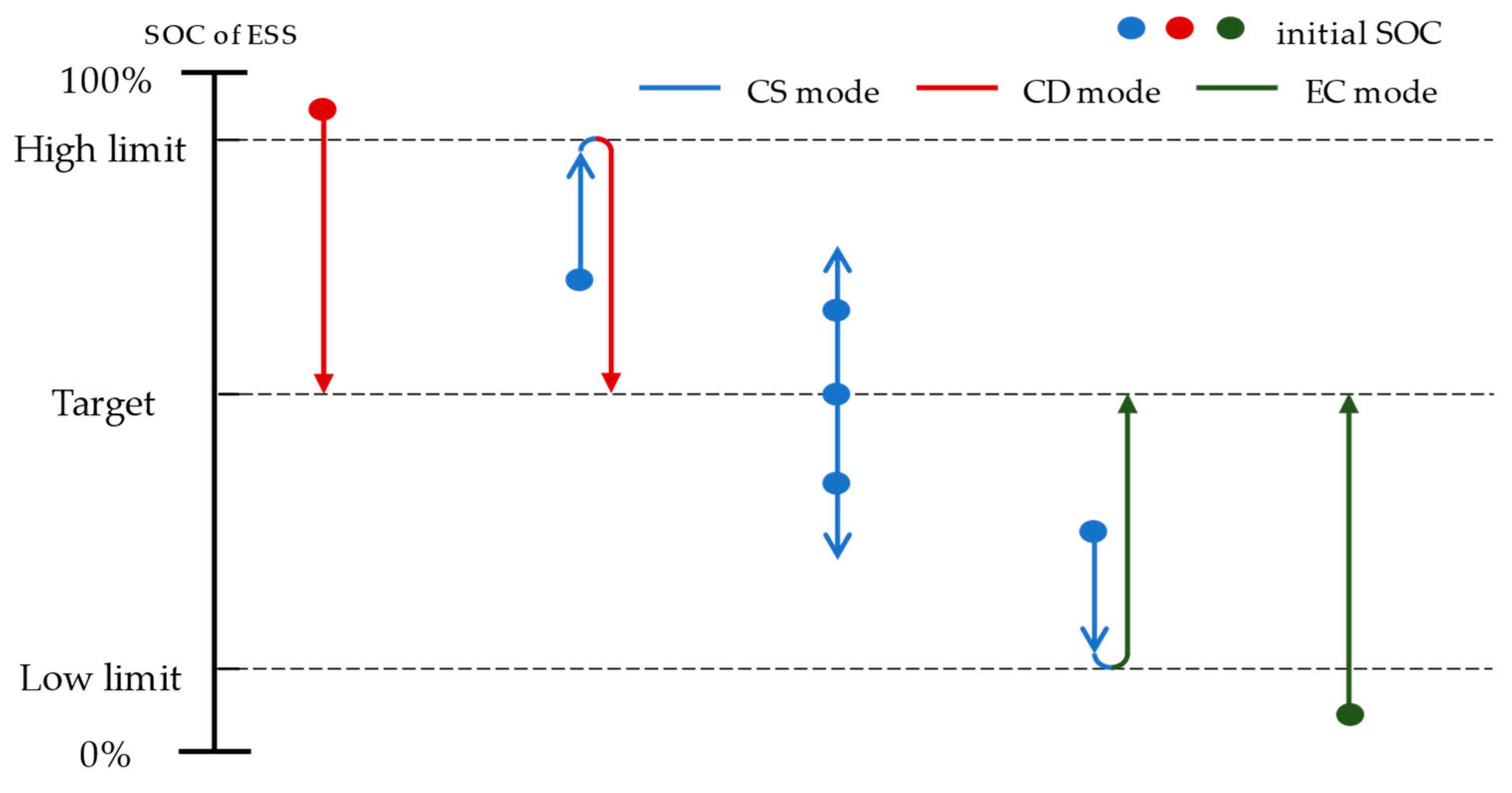
Pdem,ESS lim.The rule-based control strategy was set using three generic modes: charge sustaining (CS) mode, charge depleting (CD) mode, and emergency charging (EC) mode. The CS mode operates around the target SOC range; the CD mode is used when the SOC is higher; and the EC mode is activated when the SOC falls below a critical level. The CD and EC control mode prioritize reaching a target SOC, while the CS mode manages a current SOC to maintain around the target SOC as described in
Figure 6. Each mode has distinct characteristics, resulting in different tendencies in the fuel cell power relative to the total power demand. In other words, the main control parameters determine each control mode and energy distribution between fuel cell stacks and ESS. The most significant difference between the CD mode and CS mode is the power at which the fuel cell stacks are turned on, defined as
Pdem,fc on in
Figure 5. For example, the CD mode sets this parameter to a large value, drawing more power from the ESS while dealing with the tram’s operational power. In contrast, the CS mode sets the parameter relatively small, allowing the powertrain to rely more on fuel cell power during operation and creating more opportunities to charge the ESS using residual energy from the fuel cell stacks. Especially in the EC mode, the controller allows the fuel cell to operate at maximum power by setting the parameter as low as possible until the SOC reaches the target range of the CS mode. The remaining main control parameters are finely adjusted to satisfy boundary conditions according to a driving cycle. In general, setting them closer to low-demand will likely charge the SOC of the ESS, whereas setting them higher will tend to discharge more energy from the ESS and save hydrogen fuel. Mode changes between the three generic modes in this study are based on the simulation experiences we conducted.
3.2. ECMS-Based PMP Control
The ECMS control is an offline optimal control method that effectively manages the energy consumption of a fuel cell hybrid tram. It utilizes a mathematical equation known as the Hamiltonian, which is formulated based on the properties of the fuel cell system and ESS in
Section 2. Since both properties used in the Hamiltonian can be defined by a single factor, ECMS can easily extract the optimal control in a numerical method. The process of optimal power derivation is expressed as follows:
where
is the equivalent value called Hamiltonian,
represents the consumption rate of the hydrogen fuel,
represents the derivative of the SOC,
represents the power demanded from powertrain,
,
,
and
represent the output power and the optimal power of each fuel cell stack and ESS, respectively, and λ referred to as the ‘costate’ represents a constant value used to equalize the two energy sources [
24].
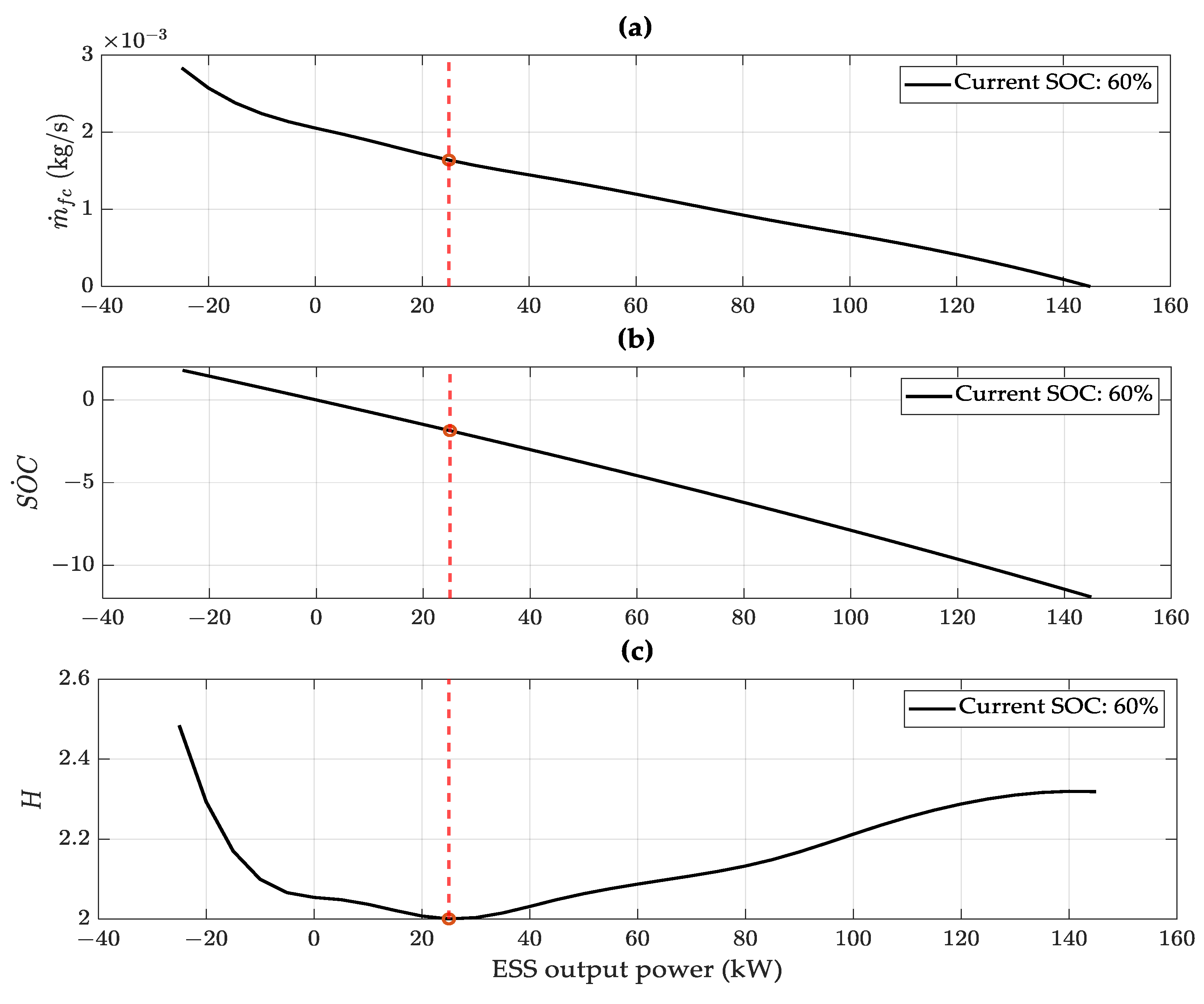
The main concept of this strategy is to minimize the Hamiltonian, which is calculated as an equivalent value using comparative factors when the demand power from the powertrain is given. As shown in
Figure 7a,b, the fuel consumption rate and SOC derivation are determined by ESS power and the Hamiltonian shows a convex characteristic as described in
Figure 7c. The optimal ESS output power is reached where the Hamiltonian reaches a minimum, marked in a red circle in
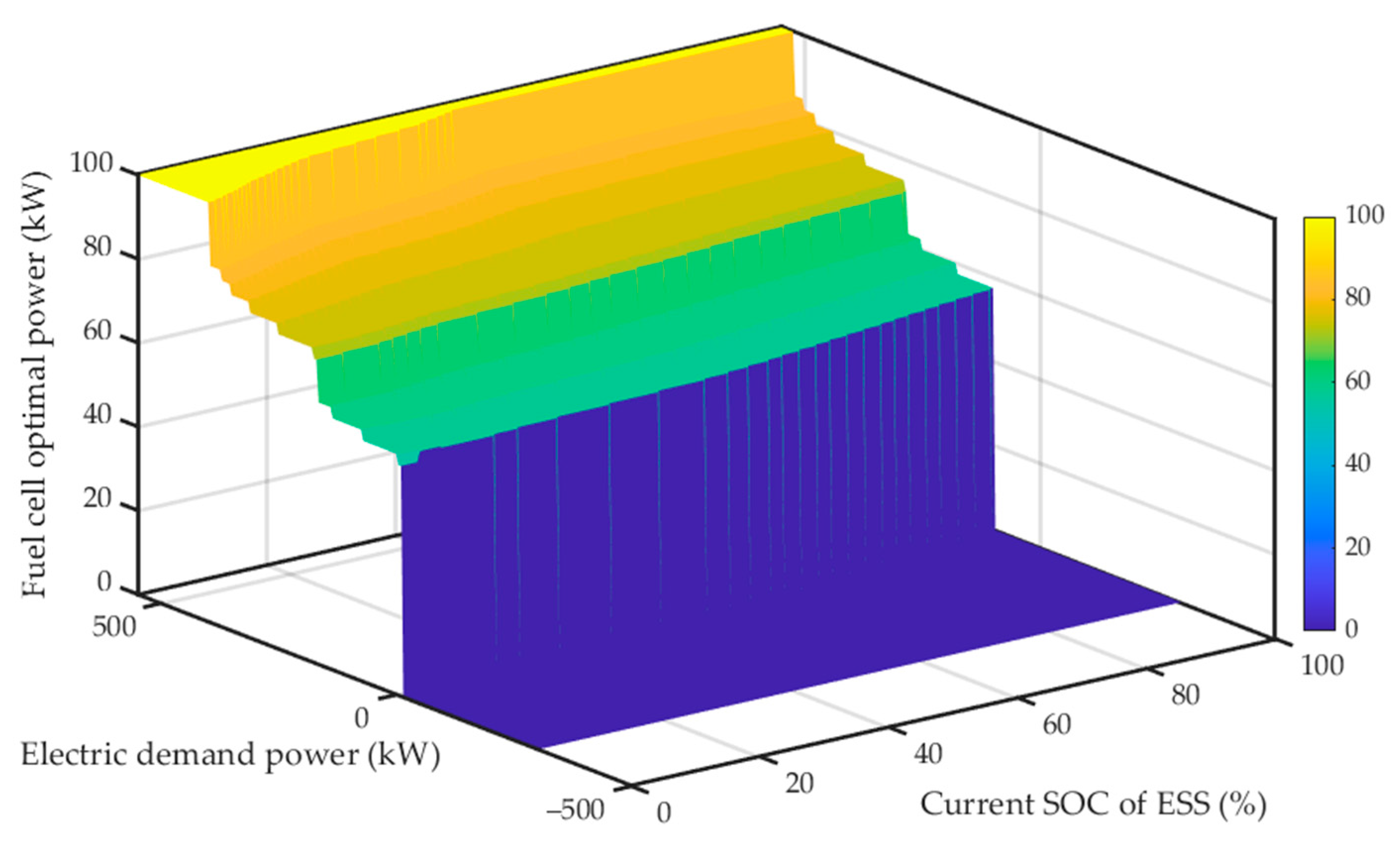
Figure 7. Since the demand power is constant, the optimal fuel cell stack power is easily derived. For this reason, it was possible to develop an optimal operation power map for all driving powers and SOC levels, as shown in
Figure 8.
The characteristics of this map are influenced by various factors. For example, the internal resistance of the ESS affects the map along the SOC index, whereas the efficiency of the fuel cell system influences its output power, aiming to maximize the overall system efficiency and minimize the equivalent consumption. In addition to the hardware properties, the ‘costate’ determines the overall tendency of the map.
4. Simulation Setting
To assess the efficiency of the various energy distribution strategies, we employed energy-based simulation models, as described in
Section 2. Each model features control strategies that are discretely configured and optimized offline, ensuring compliance with the essential boundary conditions. These conditions, which are crucial for fuel cell tram energy management simulations, require alignment of the initial and final SOC.
Regarding optimization, the methods varied between control strategies. The rule-based control line, shown in
Figure 9, resulted from a parametric study. To satisfy a boundary condition at the end of a given cycle, we tested over 1000 main control parameter sets and compared the final fuel consumption results using a large-scale simulation. The derived rule-based control is a combination of optimal parameters which result in minimum hydrogen usage with SOC alignment. Whereas the ECMS employed the shooting method. Both control strategies reflect their distinct principles: Rule-based control is parameter-dependent, whereas ECMS-based control relies on the costate λ.
In the fuel cell hybrid system, the driving force is dictated by power demand rather than the desired speed of the vehicle. Therefore, the optimization process has been conducted with a power profile [
24]. This is significantly influenced by the passenger load, which affects the achievable velocity. Although road load variations owing to mass changes are random, a consistent power demand profile guarantees the simulation stability under fixed conditions.
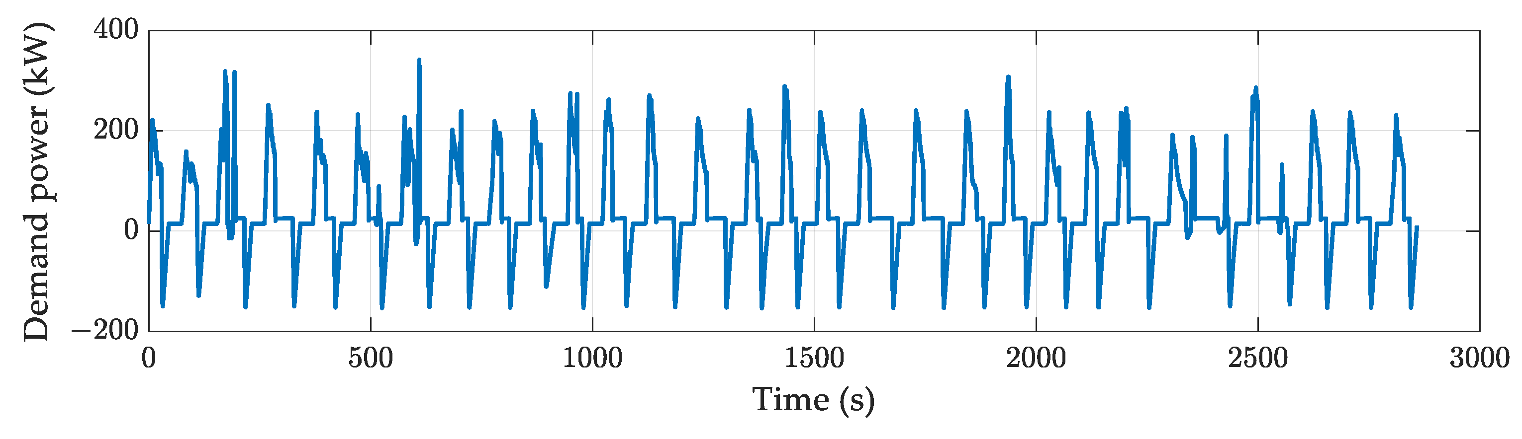
For our simulation, we used power cycle data derived from a 33.6 km driving test conducted without passengers, with the tram stopping at specific stations, as shown in
Figure 10. The tram generates maximum power at the start of the operation and regenerates power when it reaches each station. The primary distinction among the repeated cycles was the constant-speed driving range, whereas the other power-requirement trends appeared to be similar.
5. Simulation Results
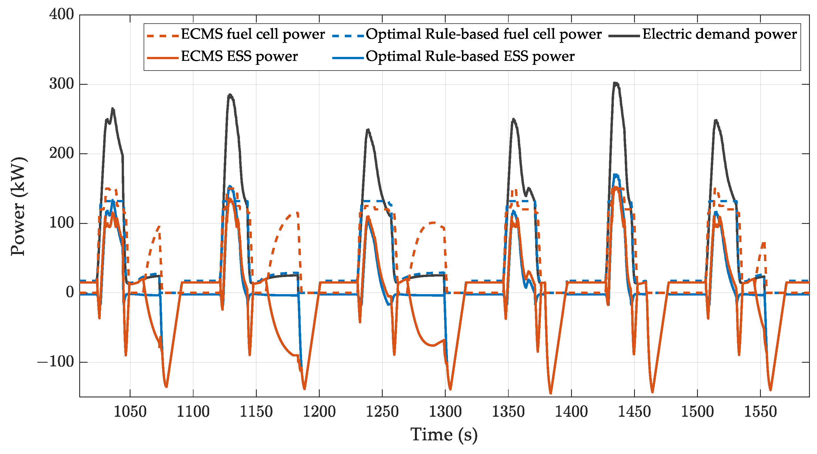
The simulation aims to compare two distinct EMS strategies in repeated pattern cycles: the rule-based control with optimized parameters and the ECMS-based control.
Figure 11 shows how these strategies affect energy distribution differently during the cycle. The optimized rule-based control strategy aims to balance the SOC level by reducing usage of ESS and supplying additional fuel cell stack power only for high-demand power. The energy discharged from the start is almost restored when reaching the stops. In contrast, the ECMS control allows the ESS to draw its power according to the SOC state at each time step. The difference in power usage between the two energy sources during propulsion is relatively small in the ECMS-based control.
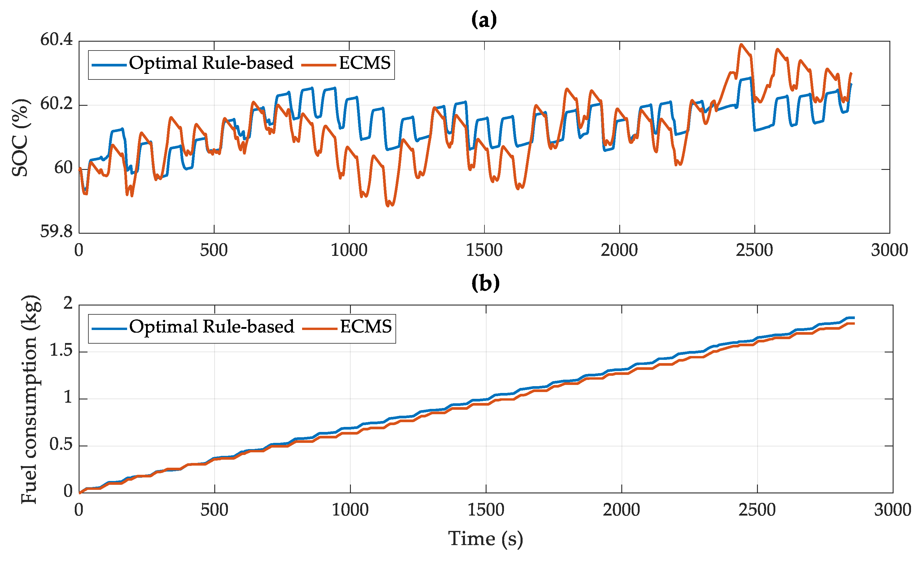
As shown in
Figure 12, the SOC trajectories for each strategy are distinct. However, both successfully satisfied the same boundary conditions, resulting in around identical SOC of 60% at the end of the simulation. This alignment across strategies reveals an interesting finding regarding hydrogen consumption: the ECMS-based control consumes less fuel than the rule-based control. The detailed simulation results are listed in
Table 2.
Hyundai Rotem’s hydrogen tanks can store 1050 L of liquid hydrogen, which is equal to 31.5 kg of weighted fuel based on the ‘Research and Development Goals by 2020′ reported by the Hydrogen and Fuel Cell Technologies Office, a Federal Agency of the United States Department of Energy (0.03 kg hydrogen per liter). According to the results of our simulation, the optimized rule-based control can drive 16.89 cycles, while the map-based ECMS control allows for 17.47 cycles of operation. In other words, the suggested control strategy secures about a 20 km driving range per one charge. This resulted in a significant reduction in fuel consumption compared to the optimized rule-based control while maintaining a higher SOC at the end of the simulation. Finally, the proposed control method charged 0.3% of SOC with 1.8207 kg hydrogen fuel during a real operation conditioned simulation.
6. Conclusions
In the simulation model, we adjusted the practical map-based ECMS to manage the energy distribution during tram operation. The results show that using the ECMS control for energy distribution results in a 3.33% reduction in fuel consumption compared to the rule-based control that is optimized for a specific cycle, even though ECMS control charged more electrical energy through ESS.
The process of manufacturing the optimal ECMS control map is categorized as ‘offline control’, considering the SOC trajectories for a given cycle. Even though ‘online control’ has the advantage of dealing with any unexpected situation, it requires a huge amount of data and is also a time-consuming task. On the other hand, owing to its repetitive driving patterns, predefined ‘offline control’ also functions effectively as real-time control by balancing fuel consumption and the state of the ESS.
The ECMS-based offline control map is designed to regulate the output power of the fuel cell stacks based on the current SOC and the power required at any given time, and most importantly, it is available directly for manufactured trams without any additional calculation once the optimization process is completed.
Our future study involves building the controller on a real fuel cell hybrid tram. Because the suggested control is simulated in ideal conditions, it needs to be confirmed in real conditions considering the degradation of the ESS and the lifespan of the fuel cell stack.


