Article

A Case Study Using Hydrogen Fuel Cell as Range Extender for Lithium Battery Electric Vehicle

1
Hainan Institute of Industry, Haikou 570204, China
2
The Mechanical and Electrical Engineering College, Hainan University, Haikou 570228, China
*
Authors to whom correspondence should be addressed.
Energies 2024, 17(7), 1521; https://doi.org/10.3390/en17071521
Submission received: 26 February 2024 / Revised: 16 March 2024 / Accepted: 20 March 2024 / Published: 22 March 2024
(This article belongs to the Section A5: Hydrogen Energy)

Abstract

:
This paper presents a case study of a lithium battery and fuel cell integrated powertrain system for a renewable energy vehicle. The performance analysis includes evaluating the energy consumption of the vehicle and the efficiency of the power generation components. When driven solely by the lithium battery at average speeds of 15 km/h and 20 km/h, it was observed that speed significantly influences the travel distance of the vehicle, with higher speeds resulting in lower mileage. The energy efficiency rates were found to be 89.3% and 85.7% at speeds of 15 km/h and 20 km/h, respectively, indicating an 18.1% decrease in efficiency from low to higher speeds. When the lithium battery is solely charged by the hydrogen fuel cell, the efficiency under test conditions reaches approximately 32.5%. In the “FC + B + SC” driving mode, which combines the use of the lithium battery, fuel cell, and solar panel to power the vehicle, the travel range can be extended to 50.62 km and 42.05 km, respectively, representing an increase of over 50%, with overall efficiencies of 63.8% and 60.7%, respectively. This hybrid powertrain system exhibits rapid dynamic response, high energy and power density, and enables longer travel distances for the renewable energy vehicle.

1. Introduction

The excessive consumption of fossil fuels is leading to escalating air pollution in China, highlighting the critical need to advance the renewable energy vehicle industry for environmental preservation [1]. Without using fossil fuels, lithium battery electric vehicles store and utilize electrical energy generated by renewable energy resources to power the vehicle, thus being more environmentally friendly and able to reduce air pollution and alleviate environmental pressure [2].
Currently, countries worldwide are conducting extensive research and strategic planning in the field of hydrogen energy [3]. Hydrogen fuel cells, serving as a clean and renewable power source, exhibit attributes such as cleanliness, high energy density, and quick refueling capabilities, making them a focal point of significant research endeavors in recent years [4]. Hydrogen fuel cell vehicles utilize hydrogen as a feedstock to convert its chemical energy into electrical energy for powering the vehicle [5].
While China initiated its hydrogen energy development relatively late, it has made substantial progress in narrowing the gap with developed nations over the past two decades. China has introduced a series of strategic plans, outlining an ambitious target of reaching one million hydrogen fuel cell vehicles by 2035 [6]. Presently, China’s indigenous technology enables fuel cell stacks with a power output up to 270 kW, cold start capability down to −52 °C, and a lifespan exceeding 15,000 to 20,000 h. In comparison, foreign fuel cells exhibit higher specifications, with a maximum power output of 300 kW, cold start performance at −60 °C, and a battery life of 25,000 h [7]. This indicates that further technological advancements are still required in China for renewable energy vehicles.
Historically, the power drive system of automobiles will experience the change from fossil fuels to lithium batteries and further to hydrogen fuel cells [8]. Nowadays, although lithium battery vehicles are developing rapidly owing to the environmental pollution and energy shortage, the number of internal combustion engine (IC) vehicles still accounts for the largest part of the automobile market. Currently, three main divisions of power system of vehicles are gasoline engine, diesel engine, and lithium battery [9]. As for the former two, although the internal combustion engine technology is comparatively mature, there is still large space for its further development. For instance, the internal combustion engines have a high heat loss which results in the lower overall efficiency of the system [10]. At present, the IC engines have the highest efficiency of 45~50%, with the peak power density and energy density between 1000~1500 W/kg and 1320~5000 W·h/kg [11]. Other disadvantages include the complex transmission system, which generates a lot of noise during the normal operation process [12].
Hybrid powertrains, a prevalent research focus in recent years, are gradually being integrated into automotive systems [13]. Lithium batteries stand out as the primary power source for current renewable energy vehicles and serve as the preferred choice for numerous commercial hybrid power transmission solutions in internal combustion engine vehicles [14]. While lithium batteries may be less potent than internal combustion engines, they offer significantly higher energy efficiency, contribute to a quieter operational experience, and generate fewer pollutants [15]. Despite the drawback of limited endurance and extended charging periods associated with lithium batteries, internal combustion engines excel in rapid dynamic response. Consequently, hybrid powertrain systems enhance vehicle versatility for a range of applications.
Hydrogen fuel cells typically operate with an efficiency of 40~60%, while boasting a power density and energy density ranging from 150~1000 W/kg to 300~1000 W·h/kg [16]. Vehicles fueled by hydrogen energy offer various advantages. Firstly, hydrogen energy is clean and its reaction generates minimal byproducts. Secondly, hydrogen cells exhibit high calorific value, low noise levels, and extended endurance. Additionally, their quick charging times are comparable to traditional fuel cars. However, despite these benefits, current hydrogen energy developments present challenges that hinder its sole use as a vehicle power source. These include low peak power, slow dynamic response, and difficulties in recovering braking energy [17]. The actual operating performance of a specific fuel cell is dependent on several factors, including the internal temperature, relative humidity of the reactant gas, and intake gas pressure [18].
Both lithium batteries and hydrogen fuel cells convert the chemical energy of the battery or hydrogen into electricity. The electrochemical energy conversion process in these devices is not constrained by the Carnot cycle and exhibits high thermal efficiency. A hybrid combination of lithium batteries and hydrogen fuel cells in a vehicle powertrain offers benefits such as zero pollutant emissions, high energy conversion efficiency, and minimum moving parts, resulting in low noise levels. Despite these advantages, practical challenges persist in their application, including issues with meeting mass production requirements, high operational costs, and the expensive construction of supporting infrastructure. These challenges pose significant barriers to the widespread adoption of hybrid powertrain vehicles of this kind.
In this study, a hybrid powertrain using a lithium battery and a hydrogen fuel cell is developed for a dual-cab pickup truck. The hydrogen fuel cell serves primarily as a range extender for the lithium-battery-powered electric vehicle, converting hydrogen’s chemical energy into electricity to recharge the lithium battery. Additionally, a solar cell is employed to recharge the lithium battery and extend the truck’s driving range for comparison purposes. The primary objectives of this study are to assess the feasibility of this hybrid power system design and to compare the effectiveness of the hydrogen fuel cell and solar cell as range extenders. The isokinetic method will be employed as the primary testing method to determine the vehicle’s mileage and energy consumption at various speeds. Through these tests, calculations and analyses will be conducted to determine the fuel cell power generation rate and efficiency, as well as the overall energy efficiency of the hybrid powertrain vehicle. The testing results will guide the energy matching and optimization of automobile components to reduce hydrogen usage costs and enhance vehicle mileage. This research on the operational parameters of lithium battery and hydrogen fuel cell vehicles aims to enhance understanding of the overall energy consumption of such vehicles and the characteristics of hydrogen fuel cells. The findings will facilitate targeted optimization of vehicle design, reduction in energy consumption, and cost savings in vehicle manufacturing and operation.

2. Experimental Setup

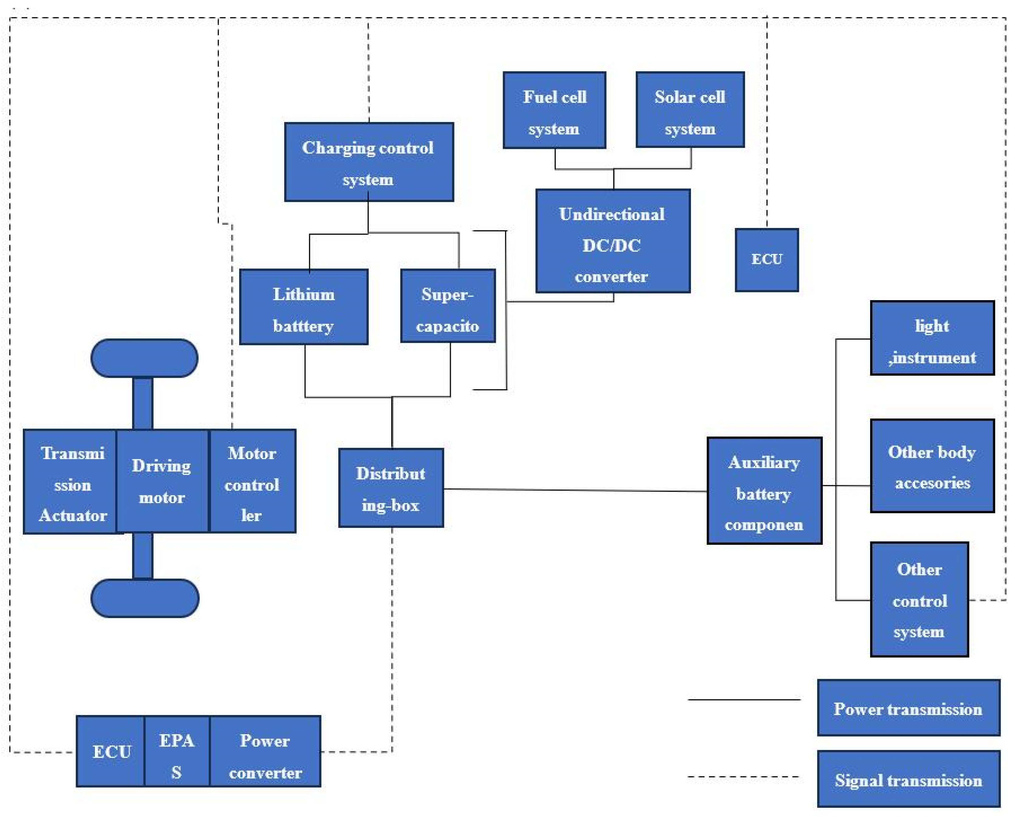
2.1. The Dynamic Structure

At present, pure fuel cell vehicles primarily employ two transmission schemes: full power and plug-in. In the full power setup, the vehicle is driven mainly by the fuel cell, with auxiliary power sources like the battery assisting during uphill acceleration and serving as an energy storage device for braking energy recovery. On the other hand, plug-in transmission types include series, parallel, and hybrid configurations. We developed the test vehicle according to the series plug-in design, where the fuel cell charges the lithium battery instead of directly driving the motor. This not only enhances the test vehicle’s mileage but also offers various advantages.
The designed test vehicle is a rear-wheel-drive vehicle equipped with high and low gear transmission ratios but lacks a braking energy recovery system. The driving strategy “FC + B + SC” entails using two solar panels to charge the lithium battery. In this setup, the lithium battery directly powers the motor, while the supercapacitor supplements energy during climbing, acceleration, and start–stop scenarios. Moreover, the fuel cell and solar panel collaboratively charge the lithium battery during operation. The supercapacitor and lithium battery operate in parallel and are linked to the drive motor. The electrical system schematic of the experimental vehicle is shown in Figure 1 and the designed vehicle is shown in Figure 2. The details of this hybrid powertrain design are as follows:
  • The hybrid power system is devised based on the plug-in extension scheme, incorporating a 500 W-rated hydrogen fuel cell to meet the system’s design specifications.
  • Due to the inadequate dynamic response of the hydrogen fuel cell under varying operating conditions, a lithium battery is integrated as the primary power source.
  • The hydrogen fuel cell recharges the lithium battery, which in turn drives the motor directly. This arrangement allows adjustment of the hydrogen fuel cell supply to meet diverse requirements such as climbing, acceleration, and driving distance, optimizing both the energy efficiency of the hydrogen fuel cell system and the performance of the test vehicle.
  • Since a fuel cell is incapable of storing or recovering electric energy, a combined driving strategy involving the lithium battery and supercapacitor is implemented to enable braking energy recovery.
  • Additionally, the stable operating condition of the fuel cell contributes to prolonging its service life.

2.2. Main Parameters of the Vehicle Body

The test vehicle underwent modification from a low-power electric vehicle, retaining its original body structure and driving motor. The alterations to its internal battery circuit included the integration of lithium batteries, as well as the incorporation of solar panels, fuel cells, and other relevant components. Following the modifications, the test vehicle achieved a maximum speed of 35.5 km/h. The vehicle’s acceleration performance was measured with a static start to 20 km/h in 6.4 s and to 30 km/h in 11.79 s. A comprehensive view of the entire vehicle can be observed in Figure 2, while the primary parameters of the vehicle body are detailed in Table 1.

2.3. Experimental Measurements

In this study, a unidirectional DC–DC converter with a voltage indicator was employed to elevate the output voltage generated by solar cells and hydrogen fuel cells. The converter has a maximal 3 A current output capability and can operate stably between 4.5 V and 80 V, aligning with the necessary charging voltage levels for lithium batteries. With this device, precise readings of input and output voltage as well as current values can be acquired, enabling the computation of power at both ends of the DC–DC converter.
During the mileage test, a wireless voltage ammeter (model VAC8010F) was employed to log the discharge state, charging energy, discharge energy, and various parameters of the lithium battery.

3. Results and Discussion

3.1. Driving Mileage Measurement of the Pure-Lithium-Battery Vehicle

During the mileage measurement, the vehicle was fully charged and driven at an average speed of either 15 km/h or 20 km/h in the same road section until it stopped automatically. The test was conducted at a relatively stable speed, devoid of pedestrian or other vehicle interference. The parameters of the lithium battery are detailed in Table 2. The satellite map depicting the test road environment is presented in Figure 3, with the test route delineated by a dotted line.
When the test vehicle operates at an average speed of 15 km/h, its speed fluctuates between 12 km/h and 17 km/h, while the battery is discharged at 0.3 C. The final mileage recorded is 33.13 km. In contrast, at an average speed of 20 km/h, the speed fluctuates within ±3 km/h, and the battery discharge ranges from 0.6 C to 1 C. The final mileage achieved was 27.14 km. Additional measured and calculated data are detailed in Table 3, with the energy consumption correlated to mileage during vehicle operation, illustrated in Figure 4. The efficiency of the vehicle energy supply system can be calculated as follows:
η s = Q B o u t + Q F C Q B i n + ( H L H V n ) / 3.6 × 10 6
where the symbol η s signifies the efficiency of the specific system; Q B o u t and Q B i n represent the discharge and charging energy of the lithium battery system, respectively; Q F C stands for the total output energy of the fuel cell system post the DC–DC converter (kW·h); H L H V denotes the lower calorific value of hydrogen, set at 241 kJ/mol; n indicates the quantity of hydrogen within the fuel cell hydrogen supply system.
Equation (1) is employed to compute the efficiency of the lithium battery system independently of the energy supplied by the hydrogen fuel cell system. Subsequently, the charge and discharge efficiencies of the lithium battery at various speeds are calculated and presented in Table 3.
When compared to a speed of 15 km/h, the mileage at 20 km/h experiences a notable reduction of 18.1%, alongside a substantial 7.7% decrease in discharge energy. Additionally, a 3.6% variance between the charge and discharge efficiency is observed. This discrepancy can be attributed to the varying discharge rates influencing the discharge capacity of the lithium battery. As the discharge rate escalates, the chemical reaction rates inside the battery accelerate and the migration speed of electrons will increase too, leading to voltage depression and a reduction in the actual available capacity of the battery [19].
In Figure 4, the energy consumption of the test vehicle exhibits a linear correlation with mileage during average speed driving. The energy consumption rates of the test vehicle are 0.039 kW·h/km at 15 km/h and 0.0439 kW·h/km at 20 km/h. Notably, the average energy consumption rate of most commercially available electric vehicles stands at 0.133 kW·h/km [20], indicating a substantial disparity between experimental and market data. This variance primarily stems from the higher motor power of commercial vehicles compared to the test vehicle, as well as the standard NEDC cycle testing conditions that involve frequent acceleration, high-speed driving, and energy-consuming factors such as air conditioner usage.

3.2. Hydrogen Fuel Cell System Analysis

3.2.1. Overall Analysis of Fuel Cells

The test vehicle incorporates a low-temperature proton exchange membrane fuel cell that solely produces gaseous water. Cold air is utilized for efficient heat dissipation, with a rated power of 500 W. To store the high-pressure gaseous H2 for the fuel cell, a high-pressure bottle with a volume of 4 L and a maximum pressure of 10 MPa is employed, while ambient air supplies the oxygen to the fuel cell. The performance parameters are detailed in Table 4.
When assessing the fuel cell’s performance, the hydrogen inlet pressure was maintained at 0.05 MPa, with the test vehicle’s lithium battery serving as the load to produce a consistent power output. The hydrogen bottle pressures were monitored before and after the stable power generation phase of the fuel cell, alongside recording the duration of power generation. The ideal gas law was applied to determine the hydrogen consumption during the reaction process. The ambient temperature was 32 °C, and the hydrogen supply rate was 5.42 × 10⁻³ mol/s. The total amount consumed was 15.87 mol of hydrogen.
After multiple iterations, the optimal power output of the DC–DC fuel cell consistently ranged between 450 W and 460 W during stable operation, averaging 456.9 W. The DC–DC’s output power remained relatively stable, fluctuating between 423 W and 426 W, with an average power of 425.1 W. These findings suggest a fuel cell output power efficiency of 93%, alongside a thermal loss of approximately 7% in the DC–DC converter. To ensure measurement precision, 24 power points were documented during testing. The optimal power values at the input and output terminals of the fuel cell DC–DC converter during operation are illustrated in Figure 4. During the test, the hydrogen supply rate was 5.42 × 10⁻³ mol/s, and the average output power of the fuel cell system was 425.1 W. The hydrogen bottle used on this test car was filled with the hydrogen at 30 °C. Based on ideal gas law, the gas bottle contained 15.87 mol of hydrogen when the gas inflation was completed, which can make the fuel cell run for 48.8 min under the same conditions and generate the total electric energy of 0.346 kW·h. Without considering the energy supply of the lithium battery pack, the overall efficiency of the fuel cell system of this test vehicle was calculated to be 32.5% according to Equation (1).

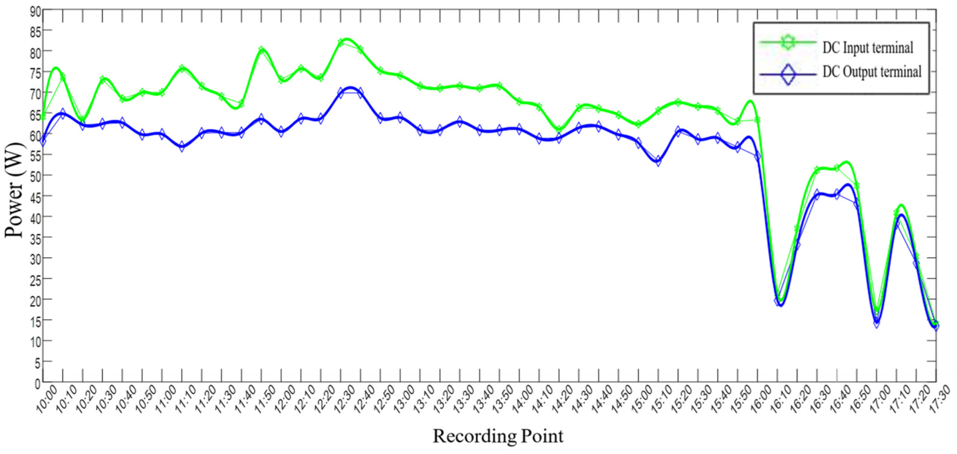
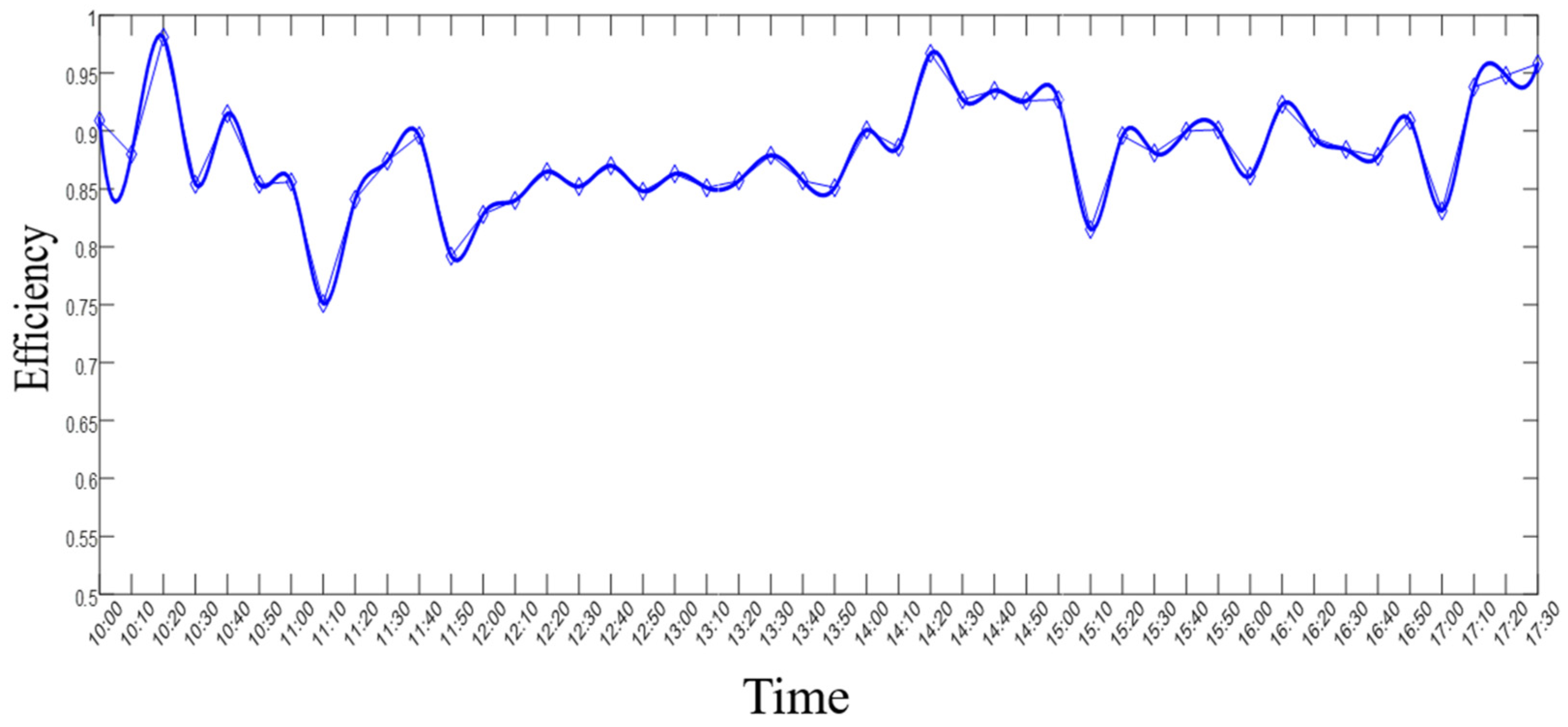
3.2.2. Solar Cell System Analysis

Two solar panels were fixed on the roof of the test vehicle and connected in the parallel mode. The electricity generated by the solar panels was boosted by the DC–DC converter to a higher voltage to charge the lithium battery. With the good weather condition under an average solar radiation of 5.1 MJ/m2 and ambient temperature of 24 °C, the power generated from the solar panel was measured continuously from 10:00 a.m. to 17:30 p.m. The input and output power of the DC–DC converter of the solar panel system were recorded at intervals of 10 min. The input/output power of the DC–DC convertor is shown in Figure 5, and the power variation trends of the solar panel DC–DC convertor are shown in Figure 6.
In Figure 6, the solar panel’s power gradually increases over time, peaking at 12:30 p.m. with a maximum input power of 82 W. Subsequently in the afternoon, the solar panel’s power diminishes progressively. This fluctuation pattern is attributed to the direct correlation between solar panel power and the sun’s radiation intensity. Notably, the significant power declines between 4:10 p.m. and 5:00 p.m., as depicted in Figure 5, are predominantly caused by cloud cover obstructing the sun, resulting in a sharp decrease in solar panel power.
Illustrated in Figure 7, the DC–DC converter efficiency varies significantly within the range of 75% to 98%, but remains relatively stable between 85% and 92%. Throughout the measurements, the average power loss of the DC–DC converter amounts to approximately 12.4%. The average input power of the DC–DC converter is approximately 62.9 W, while the average output power reaches around 55.1 W. Consequently, the total output power of the solar panel DC–DC converter during the test period is 0.418 kWh.

3.3. The Mileage of “FC + B + SC” Driving Policy

The “FC + B + SC” driving strategy integrates the subsystems of fuel cell, lithium battery, and supercapacitor to collectively power the test vehicle. This approach offers rapid dynamic response, high energy density, and high power density. Moreover, it contributes to extending the service life of both the fuel cell and lithium battery. Despite the absence of a braking energy recovery system in the test vehicle and the limited role of supercapacitors in energy storage, the mileage and energy consumption data in Section 3.1 reflect the influence of supercapacitors. Therefore, this section primarily examines the influence of the fuel cell and solar panel on the test vehicle’s driving range. Based on the above description, the key parameters of the fuel cell and solar panel utilized on the test vehicle are given in Table 5.
As observed, the energy consumption of the test vehicle exhibits a linear relationship with the traveled distance at an average speed, with minimal fluctuations in energy consumption per kilometer. The mileage achieved by the test vehicle post incorporation of the fuel cell and solar panel can be computed using the following formula:
S = S 0 + ( Q F C + Q S C ) η E
where S represents the total mileage; S0 signifies the mileage covered by the test vehicle solely with the lithium battery; QFC denotes the electrical energy produced by the hydrogen fuel cell; QSC represents the average daily energy yield of solar panels; η stands for the charge and discharge efficiency of the lithium battery at varying speeds; E denotes the average energy consumption of the lithium battery at different speeds. The computed total mileage results are detailed in Table 6.
It is seen that utilization of the “FC + B + SC” driving strategy enhances the test vehicle’s mileage by over 50% under both driving conditions. Despite the fuel cell system’s energy conversion efficiency of 32.5%, lower than that of the lithium battery, implementing the “FC + B + SC” strategy to extend mileage may reduce the overall vehicle system efficiency. Employing Equation (1), the new system efficiency reaches approximately 63.8% at an average speed of 15 km/h and 60.7% at 20 km/h.
The solar panel system exhibits a daily power output of 0.418 kWh, surpassing that of the fuel cell system on the test vehicle. However, the solar panel’s power generation rate is relatively sluggish, making it suitable for continuous use but unsuitable for rapid lithium battery charging. In contrast, the fuel cell generates 0.346 kWh of energy in 50 min. When the lithium battery power dips below a certain level, the hydrogen fuel cell system can rapidly charge the lithium battery to ensure the vehicle’s uninterrupted operation.

4. Conclusions

This study introduces an innovative integrated powertrain system that combines lithium battery and hydrogen fuel cell technologies for renewable energy vehicles. Experimental evaluations were conducted to assess the performance of this novel system. The key findings are as follows:
Under lithium battery operation at an average speed of 15 km/h, the test vehicle achieved a travel distance of 33.13 km with an energy consumption rate of 0.039 kWh/km, resulting in an efficiency of 89.3% for the lithium battery. When operating at an average speed of 20 km/h, the test vehicle covered a distance of 27.14 km with an energy consumption rate of 0.0439 kWh/km, leading to a decreased lithium battery efficiency of 85.7% and an 18.1% reduction.
The fuel cell system exhibited an efficiency of approximately 32.5% under test conditions, generating 0.346 kWh of power at a designed hydrogen supply rate of 5.42 × 10⁻³ mol/s. In comparison, the solar cell system maintained a daily power generation of 0.418 kWh. However, due to the slow electricity generation rate of the solar cell system and the rapid energy-refilling capability of the hydrogen fuel cell system, it is unsuitable for continuous operation in the test vehicle.
The “FC + B + SC” driving strategy integrates the use of lithium battery, fuel cell, and solar panel to power the test vehicle. This collaborative utilization of multiple power sources extends the vehicle’s travel range to 50.62 km and 42.05 km, reflecting an increase exceeding 50%, with overall efficiencies of 63.8% and 60.7%, correspondingly. Consequently, the “FC + B + SC” design demonstrates rapid dynamic response, high energy and power density, and the ability to enhance the travel range of renewable energy vehicles.

Author Contributions

Formal analysis, S.-T.Z.; Writing—original draft preparation, Y.-J.P.; Methodology, W.-W.W.; Investigation, H.-S.Z.; Conceptualization, Z.-L.W. All authors have read and agreed to the published version of the manuscript.

Funding

The authors thank the project of Technical Innovation of Hainan Scientific Research Institutes (KYYSGY2023-004) and Key Technology Program Fund of Haikou City (2023-031) for the financial support of this study.

Data Availability Statement

The original contributions presented in the study are included in the article, further inquiries can be directed to the corresponding author.

Conflicts of Interest

The authors declare no conflict of interest.

References

  1. Cutcliffe, S.H.; Kirsch, D.A. The Electric Vehicle and the Burden of History; Rutgers University Press: New Brunswick, NJ, USA, 2000; Volume 6, p. 326. [Google Scholar]
  2. Chan, C.; Chau, K. Modern Electric Vehicle Technology; Power Engineer; Oxford University Press (OUP): Oxford, UK, 2001; Volume 16, p. 240. [Google Scholar]
  3. Yoo, S.; Park, S. South Korea′s national pursuit for fuel cell electric vehicle development: The role of government r&d programs over 30 years (1989–2021). Int. J. Hydrogen Energy 2023, 48, 9540–9550. [Google Scholar]
  4. Zhen, H.S.; Leung, C.W.; Cheung, C.S.; Huang, Z.H. Characterization of biogas-hydrogen premixed flames using Bunsen burner. Int. J. Hydrogen Energy 2014, 39, 13292–13299. [Google Scholar] [CrossRef]
  5. Liu, Y.; Liang, J.; Song, J.; Ye, J. Research on energy management strategy of fuel cell vehicle based on multi-dimensional dynamic programming. Energies 2022, 15, 5190. [Google Scholar] [CrossRef]
  6. Rostami, M.; Manshadi, M.D.; Farajollahi, A.H.; Marefati, M. Introducing and evaluation of a new propulsion system composed of solid oxide fuel cell and downstream cycles; usage in unmanned aerial vehicles. Int. J. Hydrogen Energy 2022, 47, 13693–13709. [Google Scholar] [CrossRef]
  7. Yang, B.; Yao, M.; Li, X.; Wang, M.; Wei, D.; Li, G. Impact of Thermal Architecture on Electric Vehicle Energy Consumption and Range: A Study with Full Vehicle Simulation; SAE Technical Paper; SAE International: Warrendale, PA, USA, 2021; Volume 1, p. 0207. [Google Scholar]
  8. van Rensburg, T.M.; Brennan, N.; Howard, A. Tourist preferences for fuel cell vehicle rental: Going green with hydrogen on the island of tenerife. Int. J. Hydrogen Energy 2023, 48, 29350–29366. [Google Scholar] [CrossRef]
  9. McGovern, M.E.; Bruder, D.D.; Huemiller, E.D.; Rinker, T.J.; Bracey, J.T.; Sekol, R.C.; Abell, J.A. A review of research needs in nondestructive evaluation for quality verification in electric vehicle lithium-ion battery cell manufacturing. J. Power Sources 2023, 561, 232742. [Google Scholar] [CrossRef]
  10. Jiang, Y.; Tan, Y.; Yang, J.; Karavalakis, G.; Johnson, K.C.; Yoon, S.; Herner, J.; Durbin, T.D. Understanding elevated real-world NOx emissions: Heavy-duty diesel engine certification testing versus in-use vehicle testing. Fuel A J. Fuel Sci. 2022, 307, 121771. [Google Scholar] [CrossRef]
  11. Won, H.W.; Bouet, A. Toward the european 2030 CO2 target with gasoline compression ignition technology and 48v mild electric hybrid. Int. J. Engine Res. 2022, 24, 1190–1199. [Google Scholar] [CrossRef]
  12. Pipitone, E.; Caltabellotta, S. The potential of a separated electric compound spark-ignition engine for hybrid vehicle application. J. Eng. Gas Turbines Power Trans. ASME 2022, 144, 041016. [Google Scholar] [CrossRef]
  13. Wu, Y.; Huang, Z.; Hofmann, H.; Liu, Y.; Huang, J.; Hu, X.; Peng, J.; Song, Z. Hierarchical predictive control for electric vehicles with hybrid energy storage system under vehicle-following scenarios. Energy 2022, 251, 123774. [Google Scholar] [CrossRef]
  14. Sagar, G.V.R.; Unni, A. A study on instability and parameter drift in electric vehicle battery packs. In Proceedings of the 2022 IEEE 7th International Conference for Convergence in Technology I2CT, Pune, India, 7–9 April 2022; pp. 1–5. [Google Scholar]
  15. Wei, X.; Dou, X. Application of sustainable supply chain finance in end-of-life electric vehicle battery management: A literature review. Manag. Environ. Qual. Int. J. 2023, 34, 368–385. [Google Scholar] [CrossRef]
  16. Cheng, S.; Hu, D.; Hao, D.; Yang, Q.; Wang, J.; Feng, L.; Li, J. Investigation and analysis of proton exchange membrane fuel cell dynamic response characteristics on hydrogen consumption of fuel cell vehicle. Int. J. Hydrogen Energy 2022, 47, 15845–15864. [Google Scholar] [CrossRef]
  17. Gong, C.; Xing, L.; Liang, C.; Tu, Z. Modeling and dynamic characteristic simulation of air-cooled proton exchange membrane fuel cell stack for unmanned aerial vehicle. Renew. Energy 2022, 188, 1094–1104. [Google Scholar] [CrossRef]
  18. Fu, S.; Zhang, D.; Cha, S.W.; Chang, I.; Tian, G.; Zheng, C. An extreme gradient boosting-based thermal management strategy for proton exchange membrane fuel cell stacks. J. Power Sources 2023, 558, 232617. [Google Scholar] [CrossRef]
  19. Rostami, M.; Dehghan Manshadi, M.; Afshari, E. Performance evaluation of two proton exchange membrane and alkaline fuel cells for use in uavs by investigating the effect of operating altitude. Int. J. Energy Res. 2022, 46, 1481–1496. [Google Scholar] [CrossRef]
  20. Zhou, L.; Zhou, Y. Study on thermo-electric-hydrogen conversion mechanisms and synergistic operation on hydrogen fuel cell and electrochemical battery in energy flexible buildings. Energy Convers. Manag. 2023, 277, 116610. [Google Scholar] [CrossRef]
Figure 1. Satellite map of test road conditions and test routes.
Energies 17 01521 g001
Figure 2. The vehicle designed and tested.
Energies 17 01521 g002
Figure 3. Satellite map of test road conditions and routes.
Energies 17 01521 g003
Figure 4. Energy–mileage curve.
Energies 17 01521 g004
Figure 5. Optimal input and output power of fuel cell DC–DC converter.
Energies 17 01521 g005
Figure 6. Solar cell DC–DC input and output power–time curves.
Energies 17 01521 g006
Figure 7. Efficiency–time curve of solar cell DC–DC output terminal.
Energies 17 01521 g007
Table 1. Basic structural parameters of the vehicle.
Basic ParametersUnitNumerical Value
Length × width × heightmm3360 × 1100 × 1610
Wheelbasemm2230
Wheel trackmm1050
Front and rear suspensionsmm380/750
Radius of the tiremm240
Table 2. Parameters of lithium battery pack.
Basic ParametersUnitNumerical Value
End-of-charge voltageV73
Nominal voltageV64
Cut-off voltage of dischargeV55
Battery capacityA·h22.3
Energy of battery packkW·h1.43
Table 3. Battery performance at different speeds.
Speed
(km/h)
Working Current
(C)
Discharge Capacity
(Ah)
Charging Energy
(kW·h)
Discharge Energy
(kW·h)
Charge-Discharge Efficiency
(%)
150.318.321.4461.29289.3
200.6~1 C18.2781.3921.19385.7
Table 4. Hydrogen fuel cell parameters.
Basic ParametersUnitNumerical Value
Rated powerW500
Nominal voltageV24
Rated currentA20.84
Working temperature°C−5~35
Working pressureMPa0.045~0.06
Table 5. Key parameters of the fuel cell and solar cell power generation.
SpeedEnergy ConsumptionMileageEnergy EfficiencyBatteryGenerated Energy
15 km/h0.039 kW·h/km33.13 km89.3%Fuel cell0.346 kW·h
(10 MPa 4 L per day)
20 km/h0.0439 kW·h/km27.14 km85.7%Solar cell0.418 kW·h
(Per day)
Table 6. Mileage of “FC + B + SC” driving strategy.
SpeedTotal DistanceMileage IncrementFuel Cell Driving RangeSolar Cell Driving Range
15 km/h50.62 km52.8%7.92 km9.57 km
20 km/h42.05 km54.9%6.75 km8.16 km
Disclaimer/Publisher’s Note: The statements, opinions and data contained in all publications are solely those of the individual author(s) and contributor(s) and not of MDPI and/or the editor(s). MDPI and/or the editor(s) disclaim responsibility for any injury to people or property resulting from any ideas, methods, instructions or products referred to in the content.

