Article

On the Employment of a Chloride or Floride Salt Fuel System in Advanced Molten Salt Reactors, Part 2; Core Inventory, Fuel Burnup, and Salt Clean-Up System

1
School of Engineering, The University of Liverpool, Liverpool L69 3GH, UK
2
School of Engineering, Cardiff University, The Parade, Cardiff CF24 3AA, Wales, UK
3
School of Physical Sciences, The University of Liverpool, Liverpool L69 7ZF, UK
*
Author to whom correspondence should be addressed.
Energies 2024, 17(6), 1475; https://doi.org/10.3390/en17061475
Submission received: 27 January 2024 / Revised: 2 March 2024 / Accepted: 15 March 2024 / Published: 19 March 2024
(This article belongs to the Section B4: Nuclear Energy)

Abstract

:
Breed and Burn (B&B) fuel cycle in molten salt reactors (MSRs) qualifies this reactor type as one of the best candidates to be developed for the Gen-IV R&D program. This feature can be approached by employing a closed fuel cycle and application of a molten salt reactor as a spent nuclear fuel burner; the features promise sustainable and clean energy in the future. In this study, a complete package has been developed to calculate core inventory, fuel burnup, and salt clean-up systems of molten salt reactors during their lifetime. To achieve this, the iMAGINE-3BIC package (“iMAGINE 3D-Reg Burnup & Inventory Calculator package”) has been developed in MATLAB R2023a by employing a CINDER90 module of MCNPX 2.7 for burnup-calculation and multi-linear regression method (MLR). The package can estimate the core inventory (concentration of 25 actinides and 245 non-actinides elements) and the burnup of the reactor core during MSR lifetime (up to 100 years) while optimizing the computational resources (time, CPU and RAM), and it can even be hassle-freely executed on standalone PCs in an appropriate time due to its generous database. In addition, the salt clean-up module of the iMAGINE-3BIC package can be employed to evaluate the effects of the salt clean-up system on the above parameters over the MSRs’ lifetime. Finally, the iMAGINE-3BIC package has been applied to an iMAGINE reactor core design (University of Liverpool, UK—chloride-based salt fuel system) and an EVOL reactor core design (CNRS, Grenoble, France, fluoride-based salt fuel system) to evaluate and compare the performance of chloride/fluoride-based salt fuel MSRs from the point of burnup, core inventory, and salt clean-up systems. The results confirm that while a chloride-based salt fuel system has some advantages in less dependency on the salt clean-up system and fewer poisoning elements inventory, the fluoride-based system can achieve higher burnup during the reactor lifetime. The outcome of this study, along with the first part of this article, provides evidence to support the neutronic decision matrix as well as the pros and cons of employing chloride- or fluoride-based fuel systems in MSR cores.

1. Introduction

Generation IV nuclear reactors represent a remarkable leap forward in the evolution of nuclear energy technology, introducing a host of innovative features and design concepts that promise to address many of the challenges faced by earlier generations of reactors. Molten salt reactors (MSRs)—as one of the Gen IV candidates—represent a revolutionary approach to nuclear energy generation that offers numerous advantages over traditional solid-fuel reactors. One of the key aspects that sets MSRs apart is their remarkable fuel burnup capabilities. Fuel burnup, in the context of molten salt reactors, refers not only to the efficient utilization of nuclear fuel, where a significantly higher percentage of the fissile material is consumed before it is discarded as waste but also to their breeding cycle, which produces additional fissile material. This efficiency is a fundamental characteristic of well-designed MSRs and is central to their promise of safer, more sustainable, and potentially game-changing nuclear energy technology.
Burnup of nuclear reactors can directly affect the core inventory, breeding capabilities, and their neutronic parameters and indirectly affect thermal-hydraulic ones and even radiation damage to the fuel and structural materials. There is a strong need for a comprehensive assessment of these parameters throughout the reactor lifetime since their evolution can significantly affect the safety margins of the reactor. Considering the importance of evaluation of the MSRs burnup and its reactor core-related parameters, various research studies have been conducted that belong to one of the following categories: all employing burnup as the main parameter; (i) burnup and core inventory calculations [1,2,3,4,5,6,7,8,9,10,11,12,13,14,15,16,17,18,19,20,21], (ii) burnup optimization [15,22,23,24], (iii) salt clean-up systems [25,26,27,28,29], and, finally, (iv) waste transmutation [30,31,32,33,34].
The first step in evaluating fuel utilization in MSRs is calculating the burnup and core inventory during their life cycle and considering the effects of variables. A wide range of codes and methods are usually employed for this purpose; ORIGEN [5], SCALE [1,3,18], SERPENT [20,21], perturbation theory [13], and linear chain method [35,36] are more popular, among others. The neutron spectrum of the reactor has different effects on the core inventory of MSRs and needs to be evaluated individually [5,14]. For small-scale molten salt reactors, the difference in fuel utilization under thermal and fast spectra (both iMAGINE and EVOL) is small. However, for large-scale reactors, the achievable burnup under the fast spectrum is significantly higher than that under the thermal spectrum [12].
A molten salt fast reactor (MSFR) is predicted to work in a closed U/Pu or Th/U-based fuel cycle with a full reprocessing of all actinides in the core [22]. To reach this point, Ashraf et al. [22] modeled the primary circuit of the MSFR (European model) to optimize the concentration of the start-up liquid fuel using the code SERPENT 2.0. They have found that an MSFR was self-sustained regardless of the type of fissile materials used. The PuF3 (Pu in PuF3 is a vector of (Pu239, 0.6902), (Pu240, 0.267), (Pu241, 0.0176), and (Pu242, 0.0252) as the pair of (isotope, weight fraction), respectively) and TRUF3 (Trifluoride of Trans-Uranium elements) fuels appear to be prospective fuels compared to the 233UF4 fuel. One of the other parameters that need to be optimized is the fuel–salt combination and geometry of the MSFR core structure to identify the best candidate of fuel–salt composition from burnup optimization points and even the proportional ratio of salt (reactor core) to the moderator (usually graphite) [24]. It is important to define the salt composition with a special focus on the amount of heavy metal that can be carried in the salt. Strong computational resources are usually employed to simulate these salt combination parameters and burnup; thus, the development of artificial intelligence (AI) and machine learning (ML) methods can support the expensive computations (both time and CPU) of burnup to optimize the parameters. A fast-filtering model for burnup equilibrium state and a fast prediction model for equilibrium neutronic properties were developed based on the machine learning (ML) technique by Chen et al. [15]. Considering the various performance metrics for measuring the predicted performances of ML models in the classification and regression, the LightGBM (LGBM) model looks the most favorable for filtering the burnup state and predicting the neutronic parameters in MSFRs [15].
Molten salt fast reactors allow for continuous online fuel treatment and processing using a variety of subsystems. Among these subsystems, the salt clean-up system continuously removes fission products from the primary fuel salt and has a paramount role in the development of MSFRs [25]. The first step in this process should be identifying the key poisoning elements to be separated in MSFRs’ salt clean-up systems, as the removal of these elements that prevent the reactor from long-term operation is a vital step. A series of calculations of the amounts of the specific elements appearing in the core after a burnup of 100 GWd/tHM have identified ruthenium and molybdenum as elements with the highest influence on criticality, with each formed after 100 GWd/tHM burnup at the reasonably high concentration of 2500 to almost 4000 ppm. The next elements identified were caesium, neodymium, and palladium [26]. A salt clean-up system can be simulated through the batch execution of burnup calculation and removing the positioning elements by a manager kernel (exchanging data of modules) [25,29]. The effects of removal then can be investigated through results in comparison to the continuous burnup simulation without the removal of poisons.
Finally, one of the most important features of MSFRs is to employ this reactor type for the waste transmutation process. This application has been developed in different projects and collaborations such as MOSART [37], MARS [38], and MIMOSA [39]. This feature can be achieved through two different approaches, (i) designing MSFRs in a way that can utilize spent nuclear fuel (SNF) as a fuel source and operate in a closed fuel cycle [31,32,33] and (ii) designing waste transmuter based on MSFR technology [30,34,38]. In addition to employing MSFR technology for the latter option, Advanced Liquid-Metal Reactors (ALMRs), Particle Bed Reactors (PBRs), accelerator transmutation of waste (ATW) systems, and accelerator-driven fast reactor concepts are other systems that have been suggested by different technology developers [40]. Designing such a waste transmutation system needs an entire evaluation and assessment of burnup behavior through the reactor lifetime and finding the best steps available to achieve this goal.
Following the first part of this work [41], in this study, a new code package entitled “iMAGINE-3BIC” has been developed for an entire evaluation of burnup and core inventory during the MSR/MSFRs’ lifetime. The iMAGINE-3BIC package includes its dedicated burnup and core inventory database resulting from using the CINDER90 module of MCNPX—based on iMAGINE and EVOL (as chloride- and fluoride-based MSFRs). It employs a multi-linear regression (MLR) method that can optimize the computational cost of burnup/core inventory calculation during a long reactor lifetime (up to 100 years) while it could impose high computational costs without using this package. The developed salt clean-up module of the iMAGINE-3BIC package can also be used to apply and assess the effects of the salt clean-up system on the B&B of MSRs while considering different elements extractions. Eventually, a complete comparison has been performed on the pros and cons of chloride or fluoride salt fuel MSFRs on the burnup and core inventory parameters. In addition, the result of this study evaluates the effects of power scale-up on burnup and core inventory of zero power and demonstrator MSFRs.

2. Methodology

Understanding the importance of burnup/core inventory calculations in MSRs, which is related to one of their promised design features, i.e., closed fuel cycle, demands the development of a new package to evaluate all parameters during their long reactor lifetime without computational resource challenges. Moreover, considering some instabilities in burnup calculation employing probabilistic/Monte Carlo codes [42] can explain the importance of using new numerical features to reduce the combination of errors and the need for a huge amount of computationally intensive calculations. The iMAGINE-3BIC package has been developed to answer these challenges. Figure 1 shows the overall algorithm of the iMAGINE-3BIC package. The whole package has been made of 5 different modules: (i) input module, (ii) burnup/core inventory calculation module, (iii) multi-linear regression (MLR) module, (iv) salt clean-up module, and, finally, (v) database module.
The input module is responsible for obtaining the input parameters (including reactor design parameters and elements that need to be removed by the salt clean-up system, if any) and processing them to be fed as code input.
MCNPX uses the CINDER90 module when the BURN card is activated for burnup calculation. The CINDER90 code predicts the evolution of nuclide densities of a radioactive material, a material being exposed to neutron fields, a system with constant radionuclide production and destruction terms, or a combination of these aforementioned source terms. The latter feature allows the code to describe nuclide inventories of nuclear systems being exposed to hadronic beams, where nuclide production and destruction terms and neutron fluxes are pre-calculated by transport codes [43]. The flow diagram of CINDER90 and its coupling with MCNPX has been depicted in Figure 2.
To optimize the computational cost (CPU, RAM, and time) and most importantly calculate the burnup/core inventory parameters of the reactor core during its long lifetime (e.g., 100 years)—which takes days of computational time even on the HPC (high-performance computer), e.g., with 240 CPU cores and 100 GB RAM—a new MLR module has been developed in MATLAB. A linear regression model describes the relationship between a dependent variable, y, and one or more independent variables, x. The dependent variable is also called the response variable. Independent variables are also called explanatory or predictor variables. Continuous predictor variables are also called covariates, and categorical predictor variables are also called factors. While in a multiple linear regression (MLR) model, the response variable depends on more than one predictor variable [44].
The MLR module is employed to calculate/predict the burnup/core inventory over the reactor lifetime by applying a multiple linear regression model. The dependent and independent variables will be explained later at the end of this section.
The salt clean-up module is responsible for managing the removal of poisoning elements in burnup cycles during the reactor lifetime. The poisoning elements can be introduced by the user to this module. This is achieved by preparing a new feed at every burnup step for CINDER90 while removing or adding specific elements. A database module, as the name suggests, is used to save and interchange the output among different modules and prepare the module to show up as a package outcome.
During the development of the iMAGINE-3BIC package, the complete burnup/core inventory output parameters (from CINDER90-based on ENDF/B-VII.1) of iMAGINE Eutectic/HMR [41] and EVOL [45] cores were accumulated in the database at 50 time steps over 100 years of reactor lifetime (this procedure can be easily repeated for other design or reactor types), and as mentioned earlier, this database is accessible to other package modules. This procedure helps the MLR and salt clean-up module to extract the required parameters from the database and process it on the user-requested timestep without repeating the burnup calculation for that certain time. The iMAGINE-3BIC package supports 4 degrees of freedom (independent parameters in the MLR method) as input parameters for burnup/core inventory calculations. These input parameters and their acceptable ranges are as follows:
  • Core Type (iMAGINE-EU, iMAGINE-HMR, and EVOL or any other core whose accompanied data has been pre-defined in the database)
  • Time Domain (0–100 years, flexible time increment (Δt))
  • Power Domain (1 kW, 10 kW, 100 kW, 1 MW, 10 MW)
  • Material Domain (25 actinides and 245 non-actinides)
The package processes the inputs based on the flow diagram shown in Figure 1. The concentration of any elements (among 25 actinides and 245 non-actinides, listed in Table 1) can be found as a function of input parameters, e.g., C i = f ( c o r e   t y p e ,   t ,   P ,   Z A I D ) , where Ci is the concentration of ith element, the core type can be selected among iMAGINE Eutectic, HMR, and EVOL or anything user-defined, t presents the time, and ZAID, as has been defined in the MCNP, is the identification number of the considered elements. In the first step of the input process, the MLR module uses the multiple linear regression method to find the concentration of selected elements at time t, if t is not present in the 50 time points for which parameters are already available in the database. Then the MLR module will do a regression of the selected input with 4 independent parameters (4 degrees of freedom) between t = 0 and the selected t by the user. If the R 2 ( L e a s t   S q u a r e   M e a n ) 0.95 , then the concentration will be saved in the database as an accurate outcome, otherwise, the number of time steps considered to obtain MLR will be changed until this condition can be justified. Employing this methodology, the regression outputs for certain concentrations can be found in an acceptable range. The uncertainty of isotope concentration is one of the standard outputs of the CINDER90 module that is accessible in the database of the iMAGINE-3BIC package. In addition, the iMAGINE-3BIC package visualizes the concentration and burnup of fuel for the selected t (in the range of reactor lifetime) as 3D bar charts, which can be used properly for the comparison of parameters for different elements and core types; moreover, the concentration of all elements at different time steps are saved in individual spreadsheets.
Whenever a user calls the salt clean-up module the whole continuous (transient) process of burnup calculation (0 to t) by CINDER90 will be divided into a series of semi-batch executions to allow the package to manage the core inventory elements and remove the poisoning ones (based on user selection) at appropriate time steps. The salt clean-up module will prepare an updated input to feed the CINDER90 module to consider the effect of poisoning element separation. Results of all types of calculations are saved in the database module and can be visualized as 2D or 3D profiles based on the option selected by the user.

3. Results and Discussion

New features of fourth-generation reactors (Gen IV) aim at making nuclear energy a more reliable, sustainable, and clean energy source, which can attract more public trust and engagement. Among these features, the closed fuel cycle has been offered through molten salt reactor (MSR) developments, introducing this reactor type as a solution to the concerns about nuclear waste as they can use spent nuclear fuel either with or without prior reprocessing as their feed. This capability originated from the MSFRs’ design and, more importantly, their fuel utilization, burnup, and core inventory during reactor lifetime and breeding features that make them have a complete B&B cycle. As mentioned above, the iMAGINE-3BIC package has been developed for the purpose of quantifying the B&B capabilities of MSRs.
In this section, the output of the iMAGINE-3BIC package will be presented and concluded in three different sections: (i) iMAGINE-3BIC package sample outputs, (ii) B&B comparison of chloride- and fluoride-based MSFRs, and, finally, (iii) salt clean-up operations. Following the first part of this article series [41], iMAGINE-Eutetic (chloride-based) and EVOL (fluoride-based) MSR designs were selected as case studies. The complete design and operational parameters of these reactor types employed to obtain the following results can be found in [39,43].

3.1. iMAGINE-3BIC Package Sample Outputs

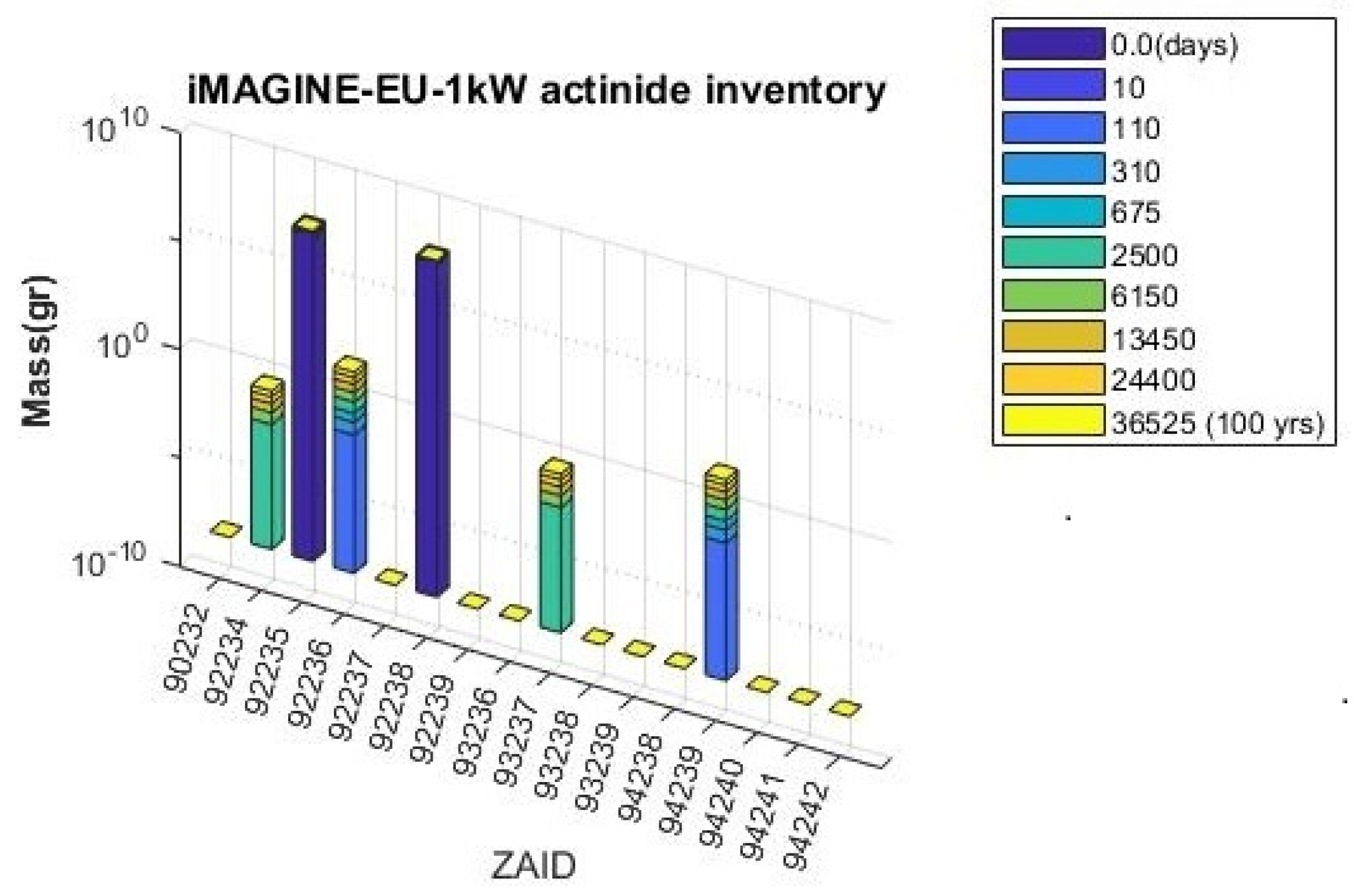
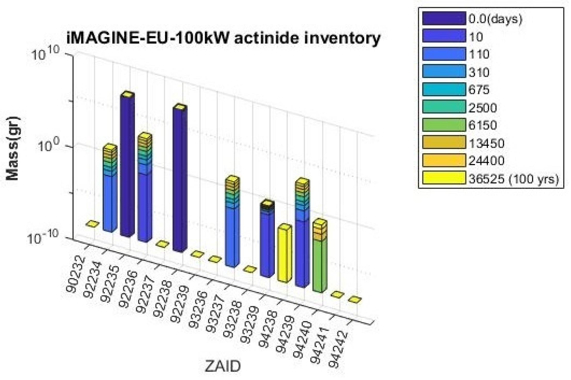
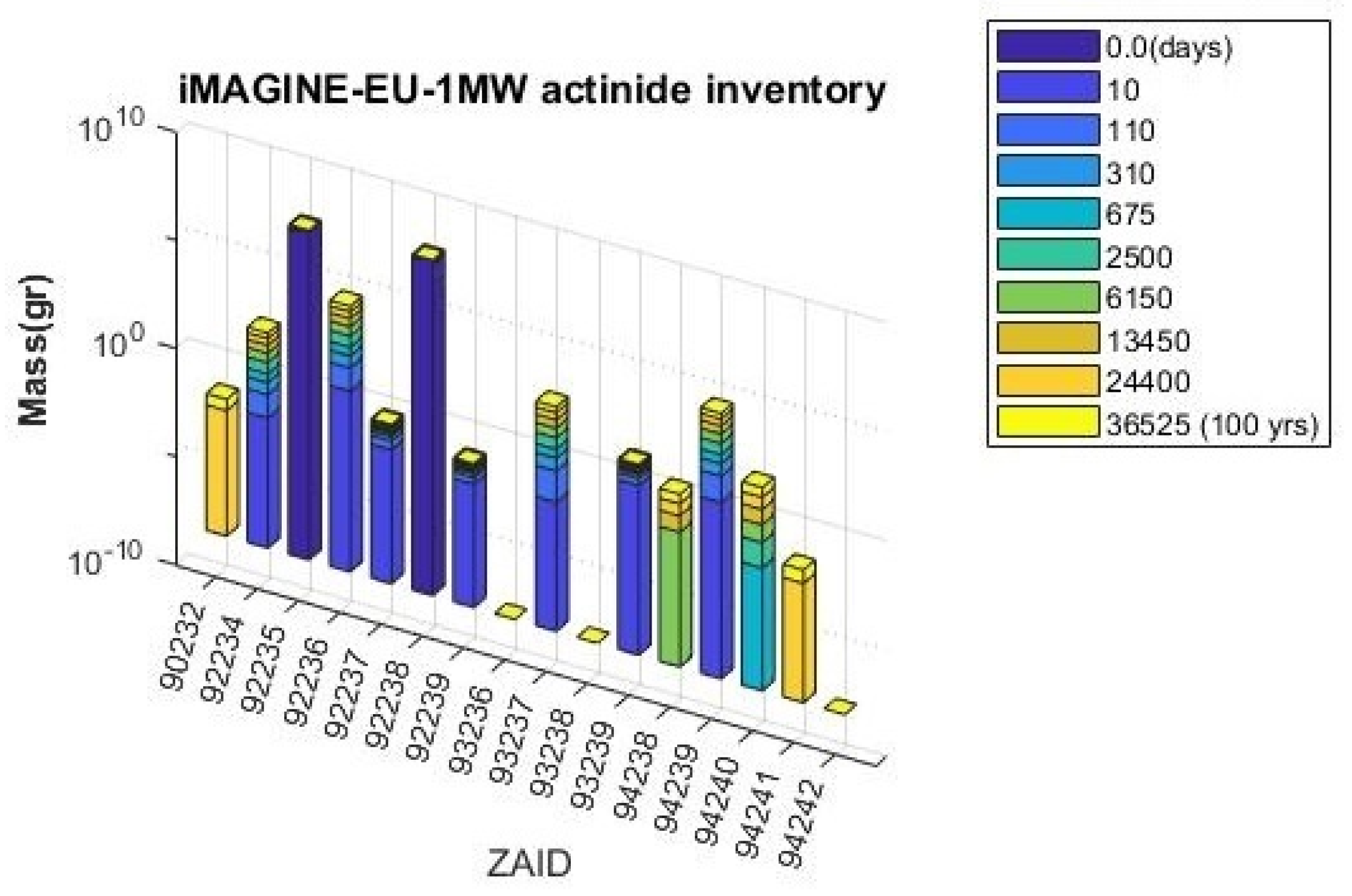
The outcome of the iMAGINE-3BIC package can be seen in Figure 3, Figure 4, Figure 5, Figure 6, Figure 7, Figure 8, Figure 9, Figure 10, Figure 11 and Figure 12 for core inventory and burnup profiles, respectively. Figure 3, Figure 4 and Figure 5 show the actinide core inventory of iMAGINE-Eutectic in the period of 0 to 100 years for the core power of 1 kW, 100 kW, and 1 MW, respectively. The concentration of different actinides and actinides inventory (25 elements listed in Table 1) as a result of the core operation and fuel burnup can be found in these figures in 10 different time steps over 100 years (omitted actinides do not exist in the core).
Time steps were selected to non-uniformly cover the entire 100 years to prove the ability of the package and have been adjusted automatically by the package to make the best multi-linear regression criteria. To evaluate the effects of power on the burnup and core inventory, this parameter has been considered at the level of 1 kW, 100 kW, and 1 MW. This selection can demonstrate the effects of power on the actinide concentrations, especially on those actinides that can not be seen (generated) at low power levels. As mentioned earlier, all the burnup and core inventory data are automatically saved by the iMAGINE-3BIC package in separate Excel files for ease of the user and can be employed for more data evaluation. These data have been listed in Table 2, Table 3 and Table 4 for the iMAGINE-Eutectic case at different power levels during the time respectively which can be used along with its relevant figures (Figure 3, Figure 4 and Figure 5).
Based on the iMAGINE design and considering the closed fuel cycle feature of MSRs, the most important actinides among others in the above figures and tables can be U235, U238, and Pu239, which complete the burn and breeding cycle (B&B) for the iMAGINE core. As can be seen in Figure 3, Figure 4 and Figure 5 and Table 2, Table 3 and Table 4, the inventory of U235 as fresh fissile material is almost constant at lower power (1 kW and 100 kW), while minor reduction can be seen at the last time steps of higher power (1 MW, Table 4 and Figure 5). U238 plays the role of fissionable material as on one hand, it can make the fission reaction with fast neutrons (fissile role), and on the other hand, it can be transmuted to Pu239 by absorbing neutrons (breeding role). The concentration of U238 follows the U235 trend, while on the opposite side, the concentration of Pu239 to Pu242 increases gradually with time and power. The even isotopes of plutonium, Pu238, Pu240, and Pu242 are not fissile, but they are fissionable, that is, they can only be split by high-energy neutrons in fast reactors like the iMAGINE core; P u 94 239 play the most important role as fertile fuel in the fast reactors.
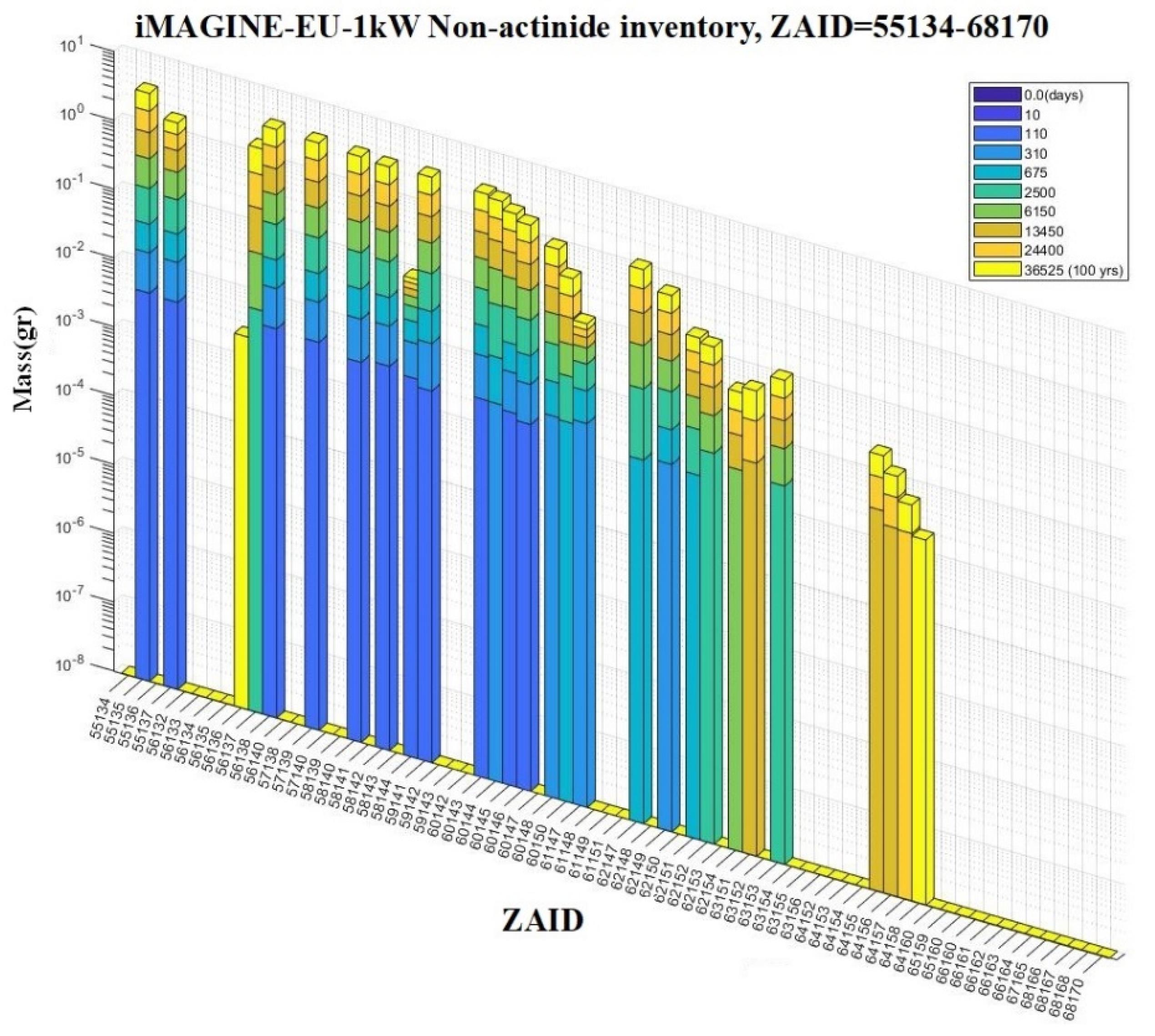
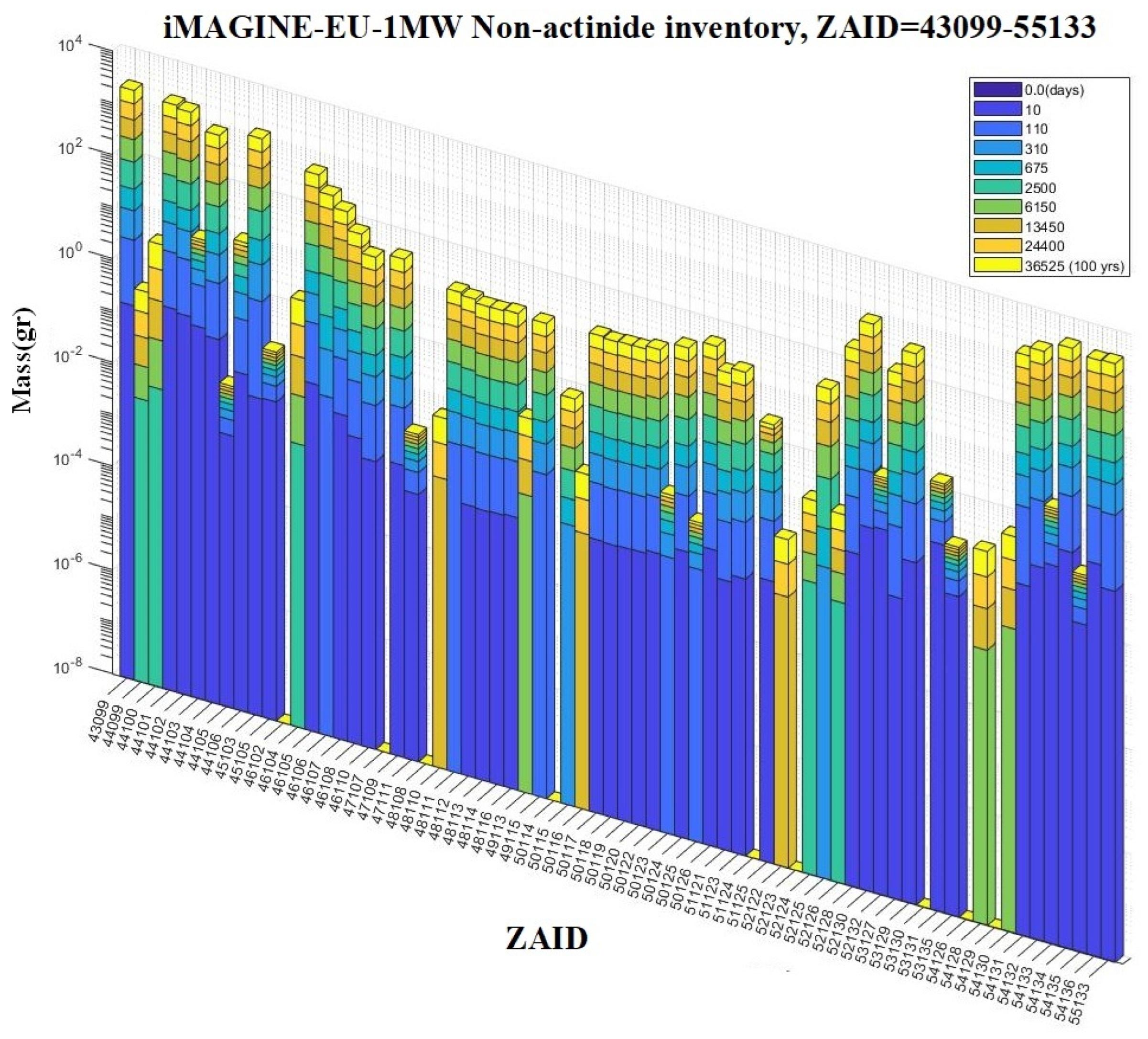
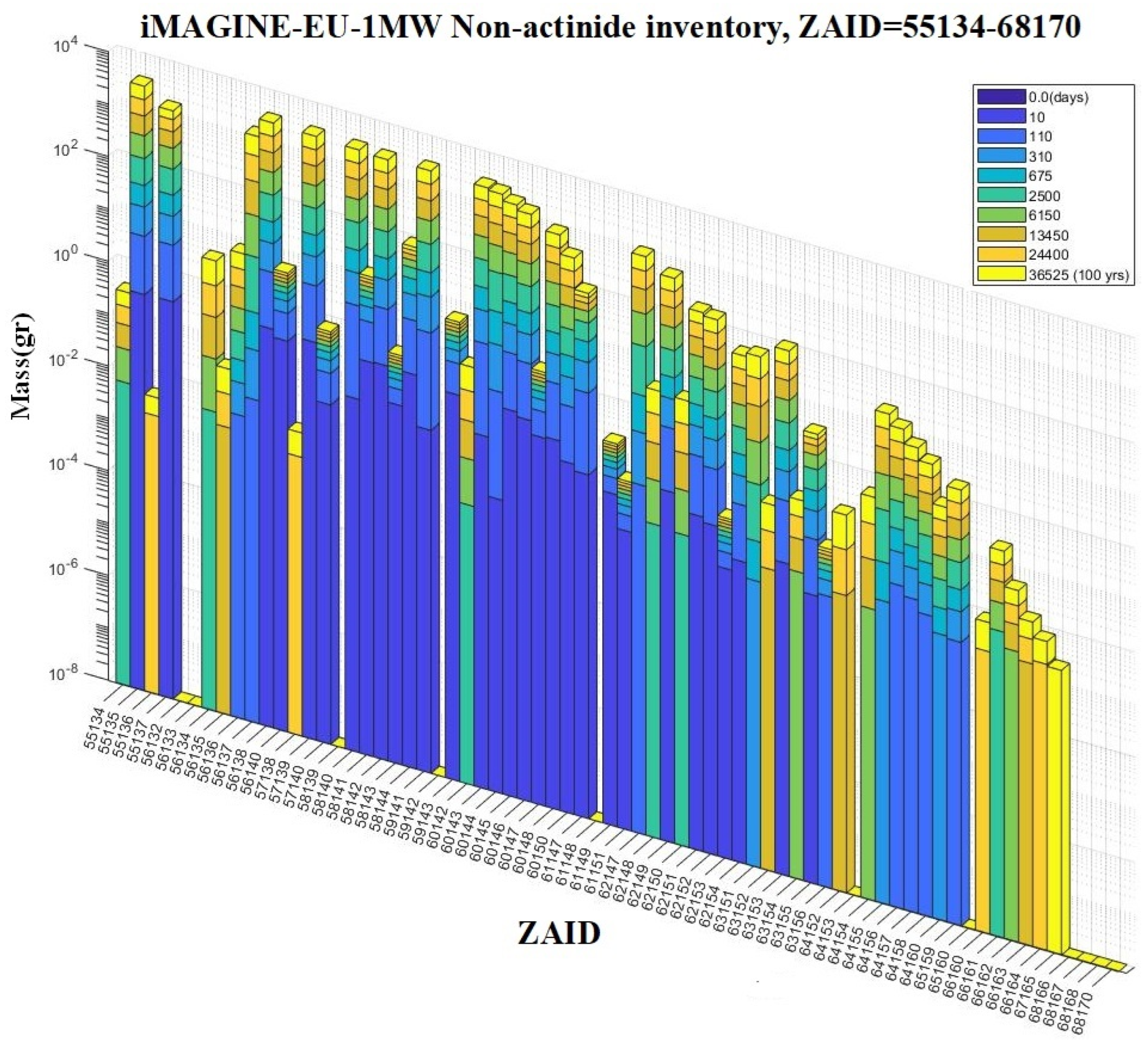
Figure 6, Figure 7, Figure 8, Figure 9, Figure 10 and Figure 11 depict the typical non-actinide inventory of the iMAGINE reactor core for 100 years of its lifetime at two different power levels, 1 kW and 1 MW (100 kW power is not shown intentionally to modify the article’s page); similar profiles were produced for iMAGINE-HMR and EVOL cores as well. As mentioned previously, the iMAGINE-3BIC package calculates and tracks the concentration of 245 non-actinide elements during reactor burnup by using the CINDER90 module. The non-actinides inventory for each power level has been presented in three continuous figures to show more details.
These figures demonstrate the detailed data on the non-actinide inventory of iMAGINE core over 100 years, and comprehensive quantitative/qualitative analysis can be extracted from them. Unlike actinide materials, non-actinide materials are generated almost from the initial time steps of the burnup cycle as a result of fission products. By raising the core power from 1 kW to 1 MW, the concentration of non-actinide material in the initial time steps has been increased where it looks reasonable as the number of fission reactions has increased significantly at the higher power level and results in more fission products.
In addition, some of the non-actinide elements, which can not be seen at lower powers, are now observed. These types of bar profiles can be appropriately employed to compare the effects of reactor power on the core inventory, compare the core inventory materials for different core designs, and, most importantly, detect poisoning non-actinide materials that need to be removed by the salt clean-up system. Similar to actinide elements, the outputs are automatically written in a spreadsheet that can be accessed through other software and modules (similar to Table 2, Table 3 and Table 4).
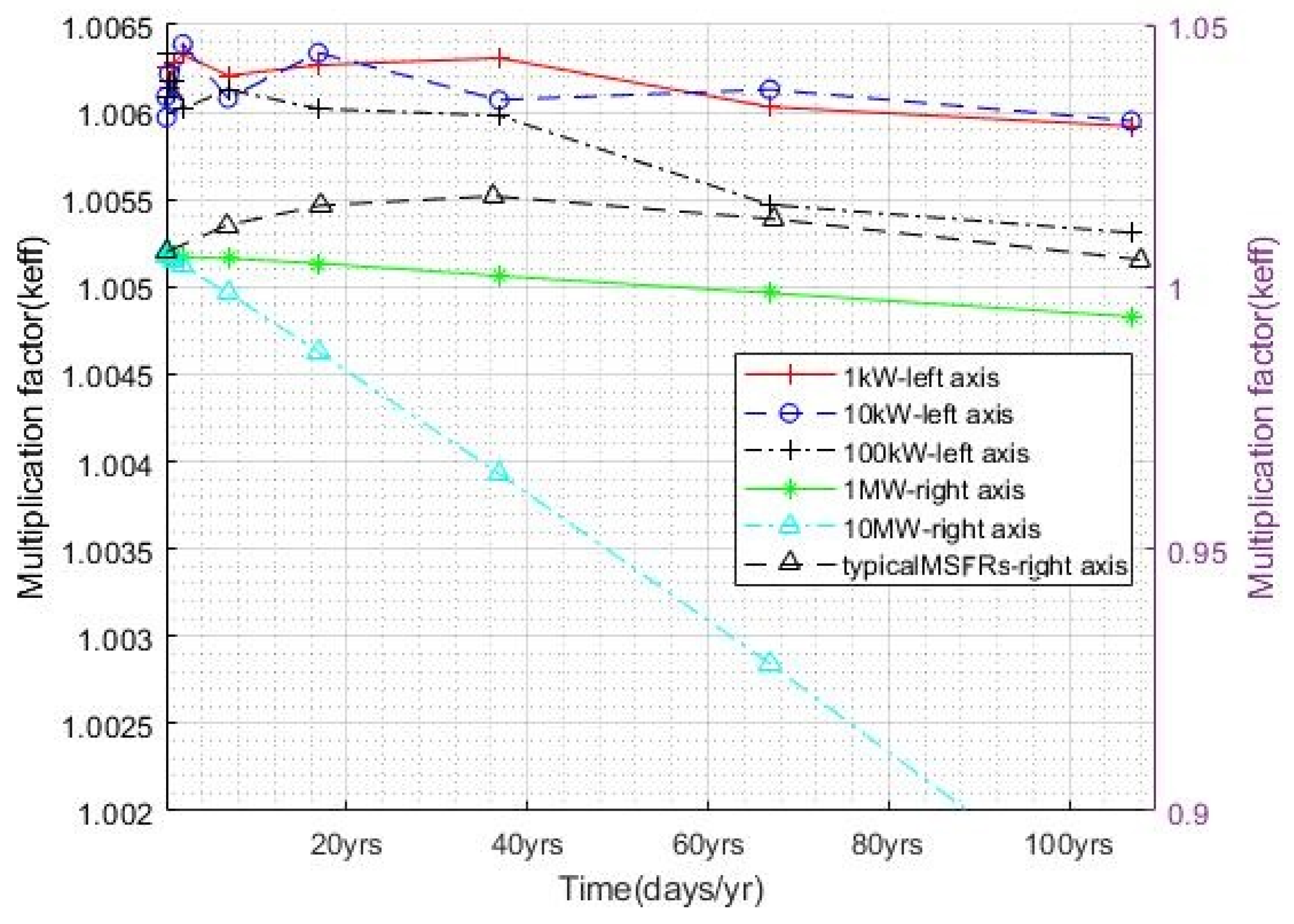
Figure 12 depicts the multiplication factor (keff) profile of the iMAGINE-Eutectic core versus the time at different power levels (the same trend can be found for the keff-burnup profile, as time and burnup play similar roles). In addition, a typical MSFR power plant profile [26] with full power operation has been depicted in this figure (black -Δ- line style). As can be observed from this figure, the multiplication factor versus time has a descending trend for the iMAGINE-Eutectic profile, while by increasing the power, the descending rate (the profile slope) has risen as a result of more fuel consumption and the reactor sooner becoming subcritical. The zero power iMAGINE-Eutectic core, as can be seen in this figure, has negligible burnup at power levels of 1–10 kW, so the profiles at this power level look almost identical without change (main intent of zero power design). It is very important to note that no breeding is expected for the zero power iMAGINE-Eutectic core because of its smaller size (in comparison to the power core) and higher fissile density (35% U235 enrichment). However, by enlarging the core size and reducing fissile material density (going from zero power to power plant), the complete B&B cycle appears, and profiles tend to be the typical MSFRs profile shown in Figure 12.

3.2. B&B Comparison of Chloride- and Fluoride-Based MSRs

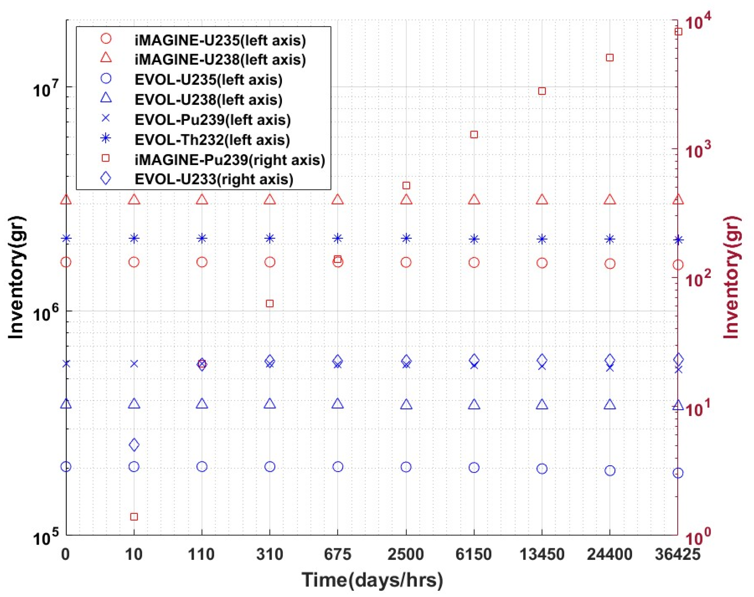
The main goal of this article series starting from the first part (Part 1: Thermophysical Properties and Core Criticality [41]) followed by this manuscript is to compare the pros and cons of using chloride- and fluoride-based salt fuels for MSFRs. In this section, iMAGINE and EVOL cores, which represent the chloride and fluoride-based salt fuels, respectively, are compared with regard to burnup/core inventory employing the iMAGINE-3BIC package (Table 5 lists their initial (fresh) salt fuel composition [41]). Figure 13 and Table 6 depict the actinides inventory of iMAGINE and EVOL cores during their reactor lifetime (100 years). To ease the evaluation process, key fissile and fertile materials of both cores, which include U233 (fissile-EVOL), U235 (fissile-both core), U238 (fissionable-both core), Pu239 (fissile-EVOL), and Th232 (fertile material-EVOL), have been considered and the other isotopes were neglected. Moreover, the core power has been set to 1 MW to properly consider the power effects on the core inventory while keeping the power in the demonstrator range (not the power plant). It is important to note that EVOL employs an additional fertile blanket in its design, which contains pure LiF-ThF4 salt with 22.5 mol% of Thorium without any fissile material. The mass of this blanket is around 44.3% of the main reactor core [45]. Figure 13 and Table 6 reveal interesting facts: (i) The iMAGINE BOC (beginning of the cycle) salt fuel composition contains about 1.7 tons of U235 fissile material, while the value for EVOL is about 0.61 tons (U235 + Pu239), with a ratio of around 2.9. Although considering the U238 as a fissionable material (in fast reactors) these values change between 4.8 tons for iMAGINE (U235 + U238) and 0.99 tons for EVOL (U235 + U238 + Pu239), with a ratio of around 4.8. Therefore, the ratio of the start-up fissile material of iMAGINE to EVOL is around 2.9–4.8, which we suppose there is a higher amount of fissile materials available in the iMAGINE fresh core. From the safety point, starting the reactor core criticality with a lower amount of fissile material can provide more safety margins; (ii) the amount of fertile material in fresh fuel for iMAGINE is about 3.1 tons of U238, while this value for EVOL core can be estimated at more than 3.4 tons (Th232 + U238 + Th232-blanket). A higher amount of fertile material in fresh fuel has a negative effect on the start-up fuel economy as well as proliferation and safety risk, especially after fuel utilization during the reactor lifetime. Moreover, the total amount of fresh fuel (fissile + fertile material) for iMAGINE is around 4.8 tons (U235 + U238), while thisvalue is around 4.2 tons (U235 + U238 + Pu239 + Th232 (in core and blanket)), which shows slightly better fresh fuel cost of the EVOL core in comparison to IMAGINE; (iii) the most important parameter in fast breeder reactors is the breeding power/ratio of the reactor core, which is a function of neutron flux and salt fuel composition. The main bred fissile material in the case of iMAGINE and EVOL reactor cores are Pu239 and U233, respectively. As can be seen in Figure 13 and Table 6, these will be produced during the reactor lifetime (column with ‘0’ values in t = 0) and be burned as new in core fissile materials. Table 6 shows that the in-core breeding power of the iMAGINE reactor core is clearly higher than the EVOL one (compare the values of U233 (EVOL) and Pu239 (iMAGINE) versus time). Even when considering the Th232 inventory of EVOL in its designed blanket, which helps to heighten the breeding power of EVOL, the breeding power of iMAGINE will still be clearly higher than EVOL and make the iMAGINE core design more competitive.
The main reason for this phenomenon is the harder neutron flux-energy spectrum of the iMAGINE reactor core as compared to the EVOL core(which has been explained in detail in Figures 9 and 10 in [41]) and, moreover, the composition of the salt fuel system. It also originated from one of the main design philosophies of the iMAGINE design that achieves self-sustained breeding in a homogeneous core. Finally, (iv) as has been mentioned previously, the breeding ratio is a function of the reactor core size, power, and fertile material content (heavy metal content). Therefore, the exact amount of the breeding ratio for iMAGINE and EVOL reactor cores can be analyzed when scaling them up from zero power to medium and high power (>100 MW), which is out of the scope of this article, which deals with a zero power design.
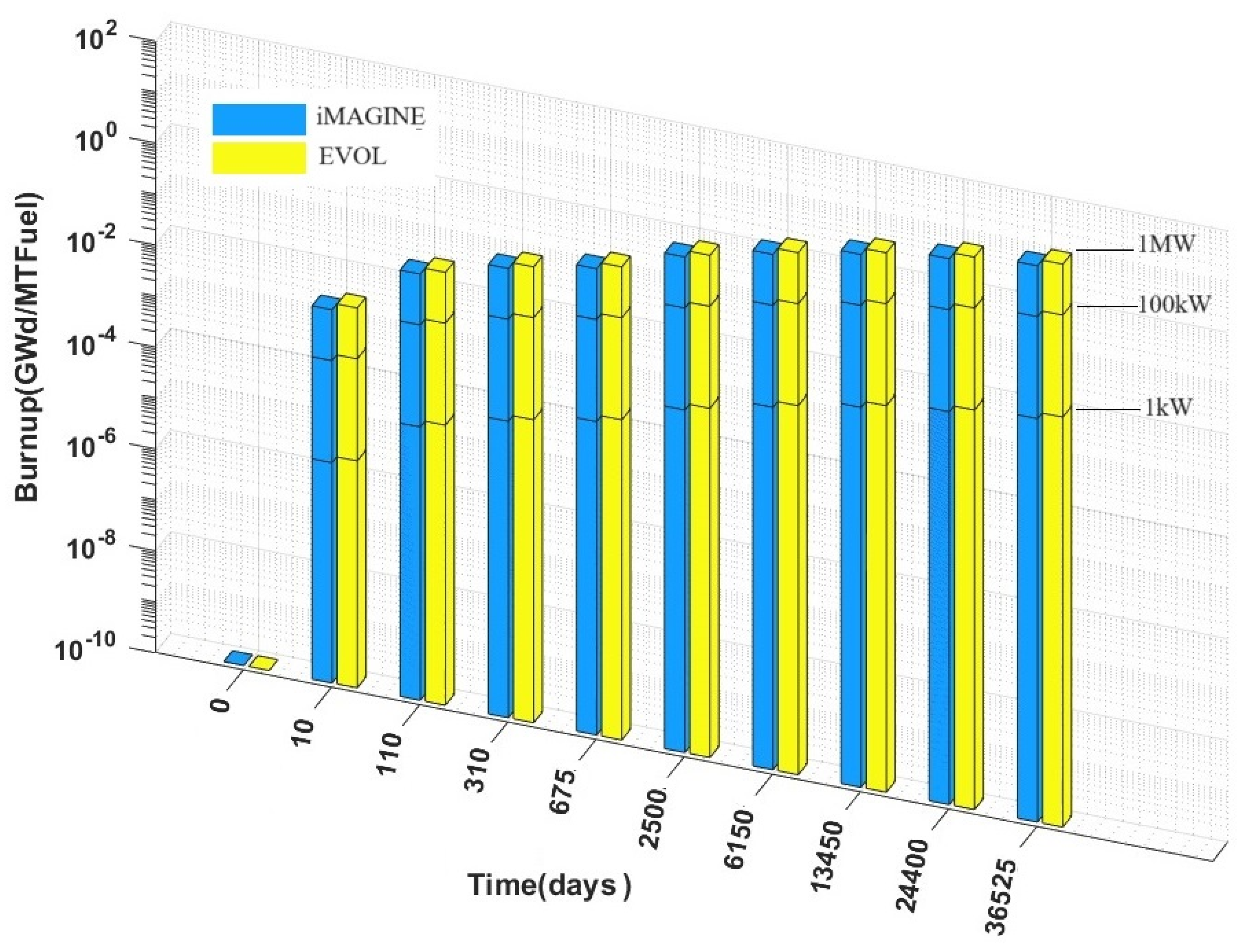
Figure 14 presents the amount of fuel burnup for iMAGINE-Eutectic and EVOL versus time during the reactors’ lifetime (100 years). These calculations were conducted at different power levels of 1 kW, 100 kW, and 1 MW for both reactor cores to consider the proper effect of power on core burnup. However, as mentioned above, to obtain the best comparison, this calculation needs to be extended to full power (>100 MW). As can be seen from this figure, the amount of burnup of the EVOL reactor core (burnup has been calculated for whole available fissile material in the core with units of (Giga Watt.day/metricTon of fuel)) is slightly higher than the iMAGINE one at different time steps. This shows the better fuel utilization in the EVOL core in comparison to iMAGINE. However, it is worth considering that the fuel in a self-sustained breeder MSFR core (like iMAGINE) is just U238 in the longer-term operation, which makes distinguished benefits for the design.
The most important factors that affect the fuel burnup are salt fuel composition, fresh core composition, and neutron flux-energy spectrum. Fuel burnup was calculated on the whole reactor core; if the amount of blanket Thorium in the EVOL design (about 44% of EVOL core mass) is added to its reactor core mass, the EVOL and iMAGINE burnup will be closer together.

3.3. Salt Clean-Up System

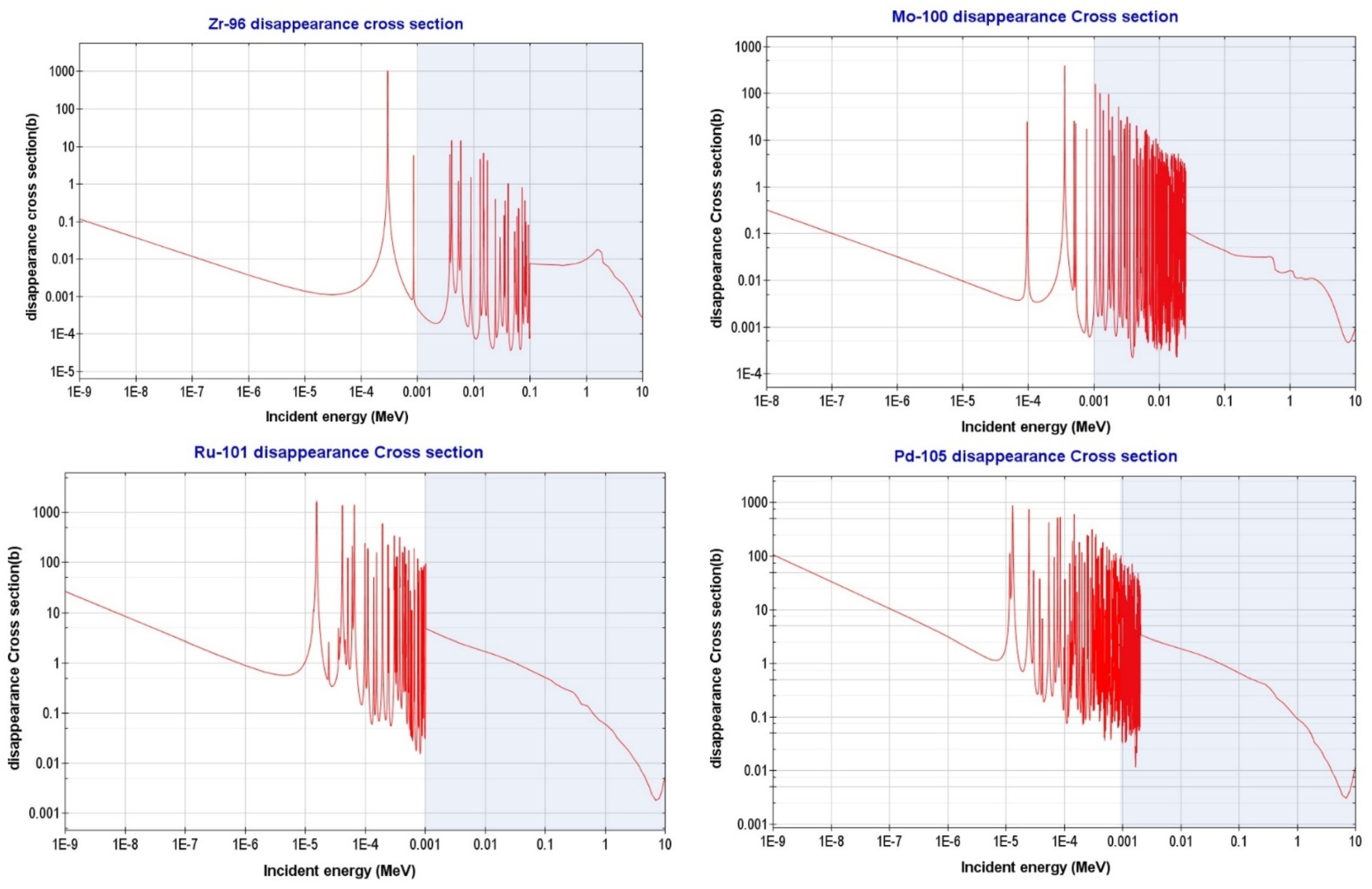
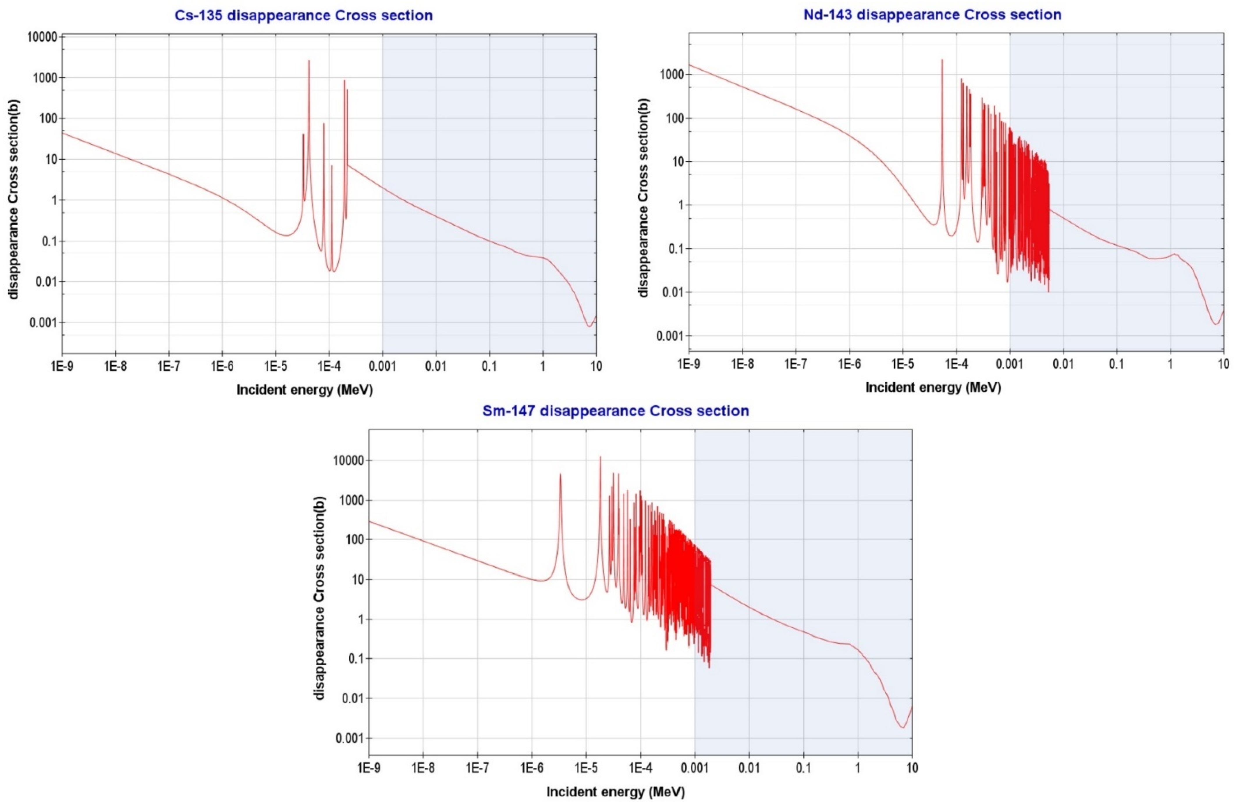
The promising feature of molten salt reactors, working with SNF (spent nuclear fuel; the SNF-based operation could use Pu from reprocessing, or it can be SNF-based without prior reprocessing like the iMAGINE design [46]) and as closed/one through fuel cycle [31,41], requires the proper treatment of salt fuel and the design of a salt clean-up system as one of the main components of molten salt fuel cycle. The main principle behind the salt clean-up system is increasing the breeding ratio and multiplication factor and, as a result, modifying the burnup and reactor lifetime (sustained reactor operation) by removing poisoning elements from the salt fuel system during the reactor operation (it can be achieved either by separating fission products (iMAGINE) or through classical reprocessing (EVOL)). These poisoning elements are generated as a result of fuel burnup and are all similar in one neutronic property: high macroscopic neutron absorption cross-section (macroscopic cross-section can be calculated by multiplying microscopic cross-section (σ) with atomic density (N)). Thus, the microscopic cross-section and the concentration of the fission product in the salt are the relevant parameters. Identifying the poisoning elements that need to be removed from the reactor core by means of a salt clean-up system is an iterative process. This can be achieved by determining the multiplication factor (keff) variation during reactor operation with and without removing suspicious poisoning elements to find those that have the highest negative effect on the multiplication factor and thus the longer-term operation. These elements can be the best candidates to be removed by a salt clean-up system to improve the neutron economy. Although this process is not a blind iteration procedure, as mentioned above, the higher concentrated non-actinides elements (among 245 elements) with higher neutron absorption cross-section (in line with reactor neutron flux-energy spectrum) can be selected and tested under this iterative process to detect the most suspicious ones. This iterative process has been conducted in various surveys [25,26,28,32] (more with deterministic neutronic codes rather than Monte Carlo ones to save time) to limit the number of suspicious non-actinide elements to the seven most important ones (and their isotopes) including Zr40, Mo42, Ru44, Pd46, Cs55, Nd60, and Sm62. The concentration of suspicious elements is the first index to select it as a poisoning element candidate, so in the first step, the concentration of all the isotopes of these seven elements was evaluated during burnup, and isotopes with low concentrations were neglected to limit the search. Table 7 shows the selected/ignored isotopes of candidate elements based on their concentration at different burnup times (isotopes with low concentration were ignored, denoted by “×”). The difference between generated neutron poisons for iMAGINE and EVOL systems has been mentioned using a light orange color, and the isotope of each element with the highest concentration has been shown in red color. In the next step to refine the key poisoning elements among others, their disappearance cross-section (these exact words were used in the ENDF library for the neutron removal cross-section) in the dedicated neutron-energy spectrum of iMAGINE and EVOL projects needs to be evaluated. The sum of the cross-sections that can lead to the disappearance of the neutron is designated as the absorption cross-section, which is the sum of the radiative capture cross-section (n,γ), (n,p) reaction cross-section, (n,T) reaction cross-section, and (n,α) reaction cross-section, where p, T, and α stand for proton, triton, and α particle. Plotting the disappearance cross-section versus energy requires the extraction of data for the appropriate reaction type (MT number) from ENDF/B-VII.1 through its format manual [47]. Based on this manual, the disappearance cross-section (MT = 101) is equal to the sum of the MT = 102–117, 155, 182, 191–193, 197 cross-section, which needs to be compiled in the ENDF library (MT numbers can be found in [47]). Following this process, Figure 15 shows that the disappearance cross-section of suspicious elements has been traced through the ENDF/B-VII.1 library by using the JANIS code [48]. In addition, the cumulative neutron-energy spectrum of iMAGINE and EVOL have been shown in Table 8 (reproduced from [41]). It can be seen in this table that most of the neutrons in the iMAGINE core have their energy in the range of 0.1 < E < 1.0 MeV (about 60%), while a significant fraction of the neutrons in the EVOL core have energies in the range of 0.01 < E < 0.1 MeV (about 43%); the tabulation of these statistical data on Figure 15 can conclude some important highlights.
(i)
Except for Zr and Mo, other elements do not have significant effects on the iMAGINE core neutron economy (by absorbing neutrons). This is because most of the neutron spectrum of the iMAGINE core (about 98% of all neutrons) has energy greater than 0.01 MeV, while the disappearance cross-section for Ru, Pd, Cs, Nd, and Sm are either low or have no resonance in this energy range, as can be seen in Table 8 and Figure 15.
(ii)
In contrast, about 20% of the neutrons in the EVOL core have energy less than 0.01 MeV (while this value is only 2% for iMAGINE) where most of the resonance for candidate poisoning elements—were shown in Figure 15—happen in this energy range. Therefore, while the poisoning elements have almost no effect on the iMAGINE neutron economy in this range, neutron absorption (considering the poisoning elements in Figure 15) can happen in the EVOL core almost 20% more in the E < 0.01 Mev energy range.
(iii)
Qualitative analysis of Figure 15 along with Table 8 determines that Zr can be a problematic poisoning material for both cores, especially for EVOL, as a large portion of the neutrons (about 43% of EVOL compared to 19% for iMAGINE) have their energies in the range of 0.1 < E < 1.0 MeV, whereas Zr96 has a high resonance absorption cross-section.
(iv)
Analysis can prove that after Zr, Mo is the next most important poisoning element for the neutron economy of both cores, as its maximum neutron disappearance resonance occurs in the range of 0.001 < E < 0.1 MeV where about 21% and 63% of total neutron population of iMAGINE and EVOL cores exist, respectively.
(v)
Considering the above-mentioned points, it seems that the effects of poisoning elements on the neutron economy are more substantial in the EVOL core rather than in the iMAGINE system. This phenomenon can happen as a result of a softer spectrum for the EVOL core (compared to a harder one for iMAGINE), which leads to a higher neutron population available in the disappearance resonance energy range (0.001 < E < 0.1 MeV) of the candidate poisoning elements, as can be clearly seen in Figure 15.
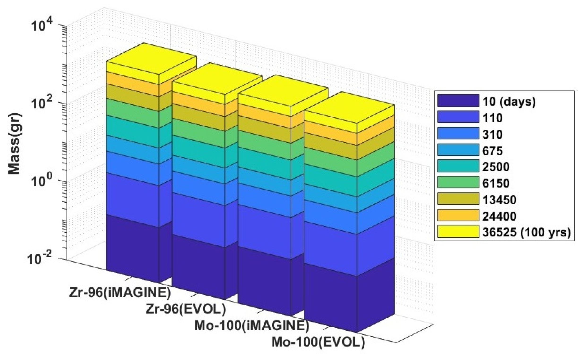
As the last step of candidate poisoning elements and salt clean-up system analysis, the concentrations of Zr96 and Mo100 (the main poisoning elements) are depicted as a function of time for different burnup periods in Figure 16. It can be seen in this figure that the amount of these poisoning elements is about 5% more in the iMAGINE reactor core compared to the EVOL one, which proportionally can lead to the same additional neutron disappearance. As a final note of this section, considering the analysis of both concentration and macroscopic cross-sections of the candidate poisoning elements, Zr and Mo need to be removed continuously by the salt clean-up system to improve the neutron economy through less non-fission absorption. The EVOL neutron energy spectrum mostly covers the resonance range of absorption cross-sections for both Zr and Mo; coupling this issue with the concentration of Zr and Mo (almost the same in different burnup periods), it can be demonstrated that the EVOL core (fluoride-based) needs more operational salt clean-up during the reactor lifetime to remove the poisoning elements.

4. Conclusions

Chloride- and fluoride-based salt compositions are the most competitive salt fuel systems considered for molten salt reactors, which promise closed fuel cycle operation and partly SNF as fresh fuel. Proper core design and analysis of burnup, core inventory, and salt clean-up system are the key elements to understanding the long-term closed fuel cycle operation capability with the possibility of SNF as fresh fuel. A complete fuel breeding and burning (B&B) cycle for this reactor type can solve the problem of nuclear waste on the one hand and on the other hand reduce the concerns of proliferation in the post-processing step of nuclear waste. This study follows its first part [41] to evaluate the pros and cons of using chloride/fluoride-based salt fuel systems in MSRs from different points of view. In this part (Part 2 of the article series) the iMAGINE-3BIC package was developed (and applied on iMAGINE and EVOL core as the candidates for chloride- and fluoride-based salts) to present the detailed burnup and core inventory information of MSFRs during their entire lifetime. The package was developed based on a Monte Carlo simulation of the reactor core by using MCNPX V2.7, burnup calculation using the CINDER module, and employing multilinear regression methods to reduce the computational cost. Multiple degrees of freedom have been considered in the package to provide enough flexibility to the user for the calculation of 25 actinides and 245 non-actinides parameters over 100 years of reactor lifetime. Table 9 summarizes the highlighted results of this evaluation based on EVOL (fluoride-based) and iMAGINE (chloride-based) salt fuel systems that can be considered along with Table 11 in Ref. [41] for more scientific evaluations. Table 9 lists the pros and cons of each fuel salt based on burnup, core inventory, and salt clean-up parameters, while the same comparison for thermophysical properties and core criticality can be found in [41].
Following Part 1 [41] and Part 2 (current manuscript) of this research series, in future studies the other less-known design features of molten salt fast reactors will be evaluated and compared with traditional NPPs. Additionally, detailed scientific simulation (neutronic and process) will be presented for salt clean-up systems of MSFRs, which is the key component to ascertain the closed fuel cycle.

Author Contributions

Conceptualization, O.N.-k. and B.M.; Methodology, O.N.-k., L.J. and B.M.; Software, O.N.-k., L.P. and A.J.; Validation, O.N.-k.; Formal analysis, O.N.-k., L.J. and B.M.; Investigation, O.N.-k., L.J., L.P., A.J., D.A. and B.M.; Resources, O.N.-k.; Data curation, O.N.-k.; Writing—original draft, O.N.-k.; Writing—review & editing, O.N.-k., L.J., D.A. and B.M.; Visualization, O.N.-k.; Supervision, B.M.; Project administration, B.M.; Funding acquisition, B.M. All authors have read and agreed to the published version of the manuscript.

Funding

The authors would like to appreciate the generous support of the Engineering and Physical Sciences Research Councils, EPSRC-UK (grant numbers: EP/V027239/1).

Data Availability Statement

The original contributions presented in the study are included in the article, further inquiries can be directed to the corresponding author.

Conflicts of Interest

The authors declare no conflict of interest.

Abbreviation

AIArtificial Intelligence
ALMRAdvanced Liquid-Metal Reactor
ATWAccelerator transmutation of waste
B&BBreed and Burn
CNRSCentre National de la Recherche Scientifique
GEN IVGeneration IV
HPCHigh-Performance Computer
MLMachine Learning
MLRMulti-Linear Regression method
MSFRMolten Salt Fast Reactor
MSRMolten Salt Reactor
NPPNuclear power Plant
PBRParticle Bed Reactors
SNFSpent Nuclear Fuel

References

  1. Merk, B.; Detkina, A.; Atkinson, S.; Litskevich, D.; Cartland-Glover, G. Evaluation of the Breeding Performance of a NaCl-UCl-Based Reactor System. Energies 2019, 12, 3853. [Google Scholar] [CrossRef]
  2. Cisneros, T. Applications of Fission Product Yields and Other Nuclear Data at TerraPower MCFR Technology; Lawrence Berkeley National Laboratory: Berkeley, CA, USA, 2023; pp. 1–8.
  3. Wicaksana, A.; Rachman, T. Molten Salt Reactor Neutronics and Fuel Cycle Modeling and Simulation with SCALE. Angew. Chemie Int. Ed. 2018, 3, 10–27. [Google Scholar]
  4. Frima, L.L.W. Burnup in a Molten Salt Fast Reactor. Dep. Radiat. Sci. Technol. 2013, 1–93. [Google Scholar]
  5. Zhou, B.; Yu, X.H.; Zou, Y.; Yang, P.; Yu, S.H.; Liu, Y.F.; Kang, X.Z.; Zhu, G.F.; Yan, R. Study on Dynamic Characteristics of Fission Products in 2 MW Molten Salt Reactor. Nucl. Sci. Tech. 2020, 31, 17. [Google Scholar] [CrossRef]
  6. Rezaie, A.; Peivaste, I.; Alahyarizadeh, G.; Minuchehr, A.; Aghaie, M. The Burnup Raising Feasibility by Studying the Effects of Th and U Contents on the Thermophysical and Mechanical Properties of Th1-XUxO2 Solid Solutions. Prog. Nucl. Energy 2021, 134, 103644. [Google Scholar] [CrossRef]
  7. Zhao, J.; Yang, Y.; Xiao, S.; Zhou, Z. Burnup Analysis of Thorium-Uranium Based Molten Salt Blanket in a Fusion-Fission Hybrid Reactor. Fusion Sci. Technol. 2013, 64, 521–524. [Google Scholar] [CrossRef]
  8. Flanagan, G. Module 4: MSR Neutronics. In Applications and Advantages of MSRs; Oak Ridge National Laboratory: Oak Ridge, TN, USA, 2017; pp. 1–30. [Google Scholar]
  9. Fiorina, C.; Lathouwers, D.; Aufiero, M.; Cammi, A.; Guerrieri, C.; Kloosterman, J.L.; Luzzi, L.; Ricotti, M.E. Modelling and Analysis of the MSFR Transient Behaviour. Ann. Nucl. Energy 2014, 64, 485–498. [Google Scholar] [CrossRef]
  10. Srivastava, A.K.; Gupta, A.; Krishnani, P.D. A Simplified Burnup Calculation Strategy with Refueling in Static Molten Salt Reactor. Int. At. Energy Agency 2015, 4, 22–23. [Google Scholar]
  11. Walker, S.A.; Tano, M.E.; Abou-Jaoude, A.; Calvin, O. Depletion-Driven Thermochemistry of Molten Salt Reactors: Review, Method, and Analysis. Front. Nucl. Eng. 2023, 2, 1–17. [Google Scholar] [CrossRef]
  12. Yu, C.; Zhu, G.; Liu, Y.; Yan, R.; Zou, Y. Comparative Study on the Neutronic Performance of Thermal and Fast Molten Salt Reactors under Once-Through Fuel Cycle. Int. J. Energy Res. 2023, 2023, 8875215. [Google Scholar] [CrossRef]
  13. Pauwels, F.; Lathouwers, D. Burnup Simulations of the Thorium Cycle in a MSFR Using Perturbation Theory; Delft University of Technology: Delft, The Netherlands, 2020. [Google Scholar]
  14. Hombourger, B.; Křepel, J.; Pautz, A. Breed-and-Burn Fuel Cycle in Molten Salt Reactors. EPJ Nucl. Sci. Technol. 2019, 5, 15. [Google Scholar] [CrossRef]
  15. Chen, S.; Zhou, J.; Cai, X.; Zou, C.; Chen, J. Machine Learning Approaches to Equilibrium Burnup Analysis for Molten Salt Reactor. Ann. Nucl. Energy 2023, 192, 109995. [Google Scholar] [CrossRef]
  16. Constable, C.; Lindley, B.; Parks, G. Maximising Discharge Burnup in an Open Cycle Molten Salt Reactor. In Proceedings of the Physor2020—International Conference on Physics of Reactors: Transition to a Scalable Nuclear Future, Cambridge, UK, 30 March–2 April 2020; pp. 2295–2302. [Google Scholar] [CrossRef]
  17. Wu, J.; Chen, J.; Cai, X.; Zou, C.; Yu, C.; Cui, Y.; Zhang, A.; Zhao, H. A Review of Molten Salt Reactor Multi-Physics Coupling Models and Development Prospects. Energies 2022, 15, 8296. [Google Scholar] [CrossRef]
  18. Zhao, X.C.; Zou, Y.; Yan, R.; Cai, X.Z. Analysis of Burnup Performance and Temperature Coefficient for a Small Modular Molten-Salt Reactor Started with Plutonium. Nucl. Sci. Tech. 2023, 34, 17. [Google Scholar] [CrossRef]
  19. Alexander, L.G. Nuclear Aspects of Molten-Salt Reactors (Chapter 14). Fluid Fuel React. 1958, 626–660. [Google Scholar]
  20. Dos, V.; Kim, K.; Pettersen, E.E.; Jensen, J.G.; Lee, D. Dynamic Burnup Studies of Seaborg Compact Molten Salt Reactor by Serpent 2. In Proceedings of the Transactions of the Korean Nuclear Society, Virtual Meeting, 17 December 2021; pp. 8–11. [Google Scholar]
  21. Wheeler, A.M.; Chvála, O. Neutronics for Fast Spectrum, Molten Salt Reactors and Evolution over Burnup. Prog. Nucl. Energy 2023, 155, 104531. [Google Scholar] [CrossRef]
  22. Ashraf, O.; Smirnov, A.D.; Tikhomirov, G.V. Nuclear Fuel Optimization for Molten Salt Fast Reactor. J. Phys. Conf. Ser. 2018, 1133, 012026. [Google Scholar] [CrossRef]
  23. Li, Z.; Wang, J.; Ding, M. A Review on Optimization Methods for Nuclear Reactor Fuel Reloading Analysis. Nucl. Eng. Des. 2022, 397, 111950. [Google Scholar] [CrossRef]
  24. Tan, M.L.; Zhu, G.F.; Zhang, Z.D.; Zou, Y.; Yu, X.H.; Yu, C.G.; Dai, Y.; Yan, R. Burnup Optimization of Once-through Molten Salt Reactors Using Enriched Uranium and Thorium. Nucl. Sci. Tech. 2022, 33, 5. [Google Scholar] [CrossRef]
  25. Vicente Valdez, P., Jr.; Betzler, B.; Wieselquist, W.; Fratoni, M. Modeling Molten Salt Reactor Fission Product Removal with SCALE; Oak Ridge National Lab: Oak Ridge, TN, USA, 2020; ISBN 1800553684.
  26. Merk, B.; Detkina, A.; Litskevich, D.; Drurdy, M.; Noori-Kalkhoran, O.; Cartland-Glover, G.; Petit, L.; Rolfo, S.; Elliot, J.P.; Mount, A.R. Defining the Challenges—Identifying the Key Poisoning Elements to Be Separated in a Future Integrated Molten Salt Fast Reactor Clean-Up System for IMAGINE. Appl. Sci. 2022, 12, 4124. [Google Scholar] [CrossRef]
  27. Dunkle, N.; Wheeler, A.; Richardson, J.; Bogetic, S.; Chvala, O.; Skutnik, S.E. Plutonium Signatures in Molten-Salt Reactor Off-Gas Tank and Safeguards Considerations. J. Nucl. Eng. 2023, 4, 391–411. [Google Scholar] [CrossRef]
  28. Merk, B.; Litskevich, D.; Gregg, R.; Mount, A.R. Demand Driven Salt Clean-up in a Molten Salt Fast Reactor—Defining a Priority List. PLoS ONE 2018, 13, e0192020. [Google Scholar] [CrossRef] [PubMed]
  29. Merk, B.; Detkina, A.; Litskevich, D.; Noori-kalkhoran, O.; Jain, L.; Cartland-Glover, G. A HELIOS-Based Dynamic Salt Clean-Up Study Analysing the Effects of a Plutonium-Based Initial Core for IMAGINE. Energies 2022, 15, 9638. [Google Scholar] [CrossRef]
  30. Li, X.; Cui, D.; Hu, G.; Cai, X.; Chen, J. Potential of Transuranics Transmutation in a Thorium-Based Chloride Salt Fast Reactor. Int. J. Energy Res. 2022, 46, 16461–16475. [Google Scholar] [CrossRef]
  31. Merk, B.; Litskevich, D.; Bankhead, M.; Taylor, R.J. An Innovative Way of Thinking Nuclear Waste Management—Neutron Physics of a Reactor Directly Operating on SNF. PLoS ONE 2017, 12, e0180703. [Google Scholar] [CrossRef]
  32. Merk, B.R.; Detkina, A.; Noori-kalkhoran, O.; Jain, L.; Litskevich, D.; Cartland-glover, G.; Scholar, G. New Waste Management Options Created by IMAGINE through Direct Operation on SNF Feed. Energies 2023, 16, 7420. [Google Scholar] [CrossRef]
  33. Robert, B.; Brown, E.B. Molten Salt Reactor Technology for Partitioning & Transmutation and Harmonisation of the Future Nuclear Fuel Cycle. 2004, pp. 1–14. Available online: https://www.oecd-nea.org/pt/docs/iem/mol98/session2/SIIpaper8.pdf (accessed on 16 December 2023).
  34. Wicaksana, A.; Rachman, T. The AMSTER Concept (Actinides Molten Salt Transmuter). Angew. Chemie Int. Ed. 2018, 3, 10–27. [Google Scholar]
  35. Stanisz, P.; Cetnar, J.; Oettingen, M. Radionuclide Neutron Source Trajectories in the Closed Nuclear Fuel Cycle. Nukleonika 2019, 64, 3–9. [Google Scholar] [CrossRef]
  36. Cetnar, J.; Stanisz, P.; Oettingen, M. Linear Chain Method for Numerical Modelling of Burnup Systems. Energies 2021, 14, 1520. [Google Scholar] [CrossRef]
  37. Ignatiev, V.; Feynberg, O.; Gnidoi, I.; Merzlyakov, A.; Surenkov, A.; Uglov, V.; Zagnitko, A.; Subbotin, V.; Sannikov, I.; Toropov, A.; et al. Molten Salt Actinide Recycler and Transforming System without and with Th-U Support: Fuel Cycle Flexibility and Key Material Properties. Ann. Nucl. Energy 2014, 64, 408–420. [Google Scholar] [CrossRef]
  38. Ignatiev, V.; Feynberg, O.; Gnidoi, I.; Konakov, S.; Kormilitsyn, M.; Merzliakov, A.; Surenkov, A.; Uglov, V.; Zagnitko, A. MARS: Story on Molten Salt Actinide Recycler and Transmuter Development by Rosatom in Co-Operation with Euratom; International Atomic Energy Agency: Vienna, Austria, 2015; pp. 92–103. [Google Scholar]
  39. MultI-Recycling Strategies of LWR SNF Focusing on MOlten SAlt Technology (MIMOSA). Available online: https://www.mimosa-euratom.eu/ (accessed on 16 December 2023).
  40. Committee on Separations Technology and Transmutation Systems—National Research Council. Nuclear Wastes: Technologies for Separations and Transmutation; National Research Council: Washington, DC, USA, 1996; Volume 12, ISBN 9780309052269.
  41. Noori-kalkhoran, O.; Litskevich, D.; Detkina, A.; Jain, L.; Cartland-glover, G.; Merk, B. On the Employment of a Chloride or Fluoride Salt Fuel System Properties and Core Criticality. Energies 2022, 15, 8865. [Google Scholar] [CrossRef]
  42. Kępisty, G.; Cetnar, J. Instabilities of Monte-Carlo Burnup Calculations for Nuclear Reactors—Demonstration and Dependence from Time Step Model. Nucl. Eng. Des. 2015, 286, 49–59. [Google Scholar] [CrossRef]
  43. Gallmeier, F.X.; Iverson, E.B.; Ferguson, P.D.; Holloway, S.T.; Kelsey, C.; Muhrer, G.; Pitcher, E.; Wohlmuther, M.; Micklich, B. The CINDER’90 Transmutation Code Package for Use in Accelerator Applications in Combination with MCNPX. In Proceedings of the ICANS XIX, 19th Meeting on Collaboration of Advanced Neutron Sources, Grindelwald, Switzerland, 8–12 March 2010. [Google Scholar]
  44. The MathWorks Inc. Multiple Linear Regression. Available online: https://uk.mathworks.com/help/stats/multiple-linear-regression-1.html (accessed on 16 December 2023).
  45. Evaluation and Viability of Liquid Fuel Fast Reactor System-EVOL (Project N 249696); Final Report, 2015. Available online: https://cordis.europa.eu/project/id/249696 (accessed on 16 December 2023).
  46. Merk, B.; Litskevich, D.; Peakman, A.; Benkhad, M. IMAGINE—A Disruptive Change to Nuclear or How Can We Make More Out of the Existing Spent Nuclear Fuel and What Has to Be Done to Make It Possible in the UK? Awt-Int. Z. Fuer Kernenerg. 2019, 64, 353–359. [Google Scholar]
  47. Herman, M.; Trkov, A. ENDF-6 Formats Manual; Rep. BNL-90365-2009; International Atomic Energy Agency: Vienna, Austria, 2009; Volume 392. [Google Scholar]
  48. NEA Janis 4.0 User’s Guide; Nuclear Energy Agency: Paris, France, 2013; pp. 1–85.
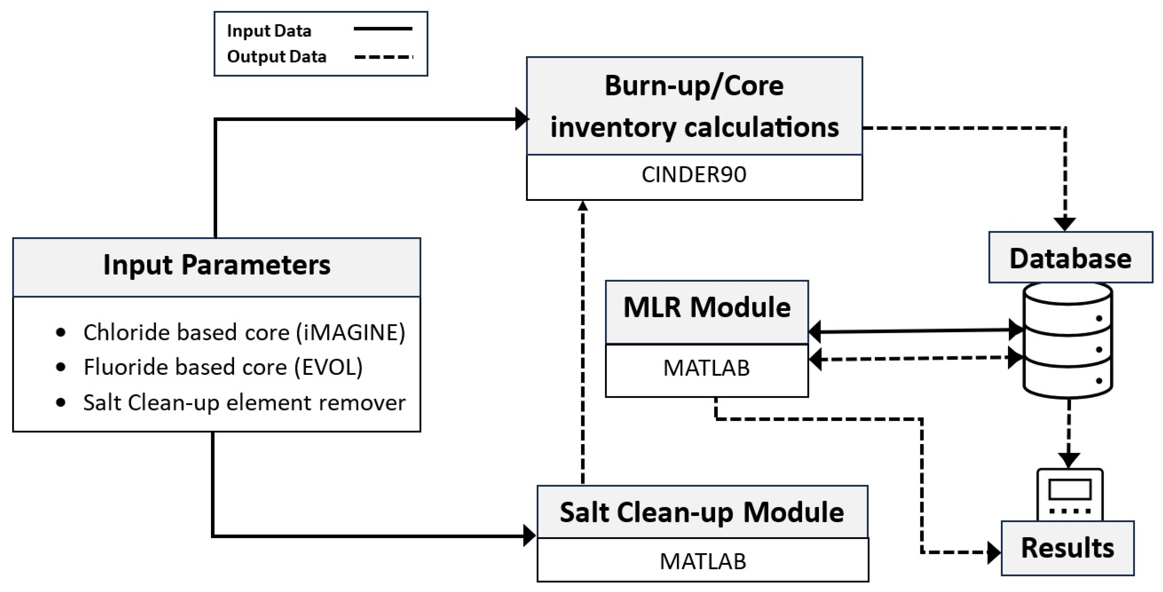
Figure 1. Algorithm of the iMAGINE-3BIC package.
Energies 17 01475 g001
Figure 2. Flow diagram of the CINDER90 code.
Energies 17 01475 g002
Figure 3. Actinide inventory of a 1 kW iMAGINE−Eutectic core for 100 years.
Energies 17 01475 g003
Figure 4. Actinide inventory of a 100 kW iMAGINE−Eutectic core over 100 years.
Energies 17 01475 g004
Figure 5. Actinide inventory of a 1 MW iMAGINE−Eutectic core over 100 years.
Energies 17 01475 g005
Figure 6. Non-actinide inventory of a 1 kW iMAGINE−Eutectic core over 100 years, ZAID = 9019-42100.
Energies 17 01475 g006
Figure 7. Non-actinide inventory of a 1 kW iMAGINE−Eutectic core over 100 years, ZAID = 43099-55133.
Energies 17 01475 g007
Figure 8. Non-actinide inventory of a 1 kW iMAGINE−Eutectic core over 100 years, ZAID = 5513-68170.
Energies 17 01475 g008
Figure 9. Non-actinide inventory of a 1 MW iMAGINE−Eutectic core over 100 years, ZAID = 9019-42100.
Energies 17 01475 g009
Figure 10. Non-actinide inventory of a 1 MW iMAGINE−Eutectic core over 100 years, ZAID = 43099-55133.
Energies 17 01475 g010
Figure 11. Non-actinide inventory of a 1 MW iMAGINE−Eutectic core over 100 years, ZAID = 55134-68170.
Energies 17 01475 g011
Figure 12. Multiplication factor (keff) versus time for iMAGINE−Eutetic at different power levels.
Energies 17 01475 g012
Figure 13. Actinides inventory of iMAGINE−Eutectic and EVOL 1 MW cores versus time.
Energies 17 01475 g013
Figure 14. iMAGINE−Eutectic and EVOL fuel burnup versus time during the reactors’ lifetime over 100 years.
Energies 17 01475 g014
Figure 15. Disappearance cross-section vs. energy for candidate elements (the blue part determines the fast energy neutrons).
Energies 17 01475 g015aEnergies 17 01475 g015b
Figure 16. Zr96 and Mo100 concentrations at different burnup periods (time).
Energies 17 01475 g016
Table 1. List of actinide and non-actinide elements available in the iMAGINE-3BIC package.
Non-ActinidieActinide
Ga69Ga 71GaI127I 129I 130I 131I 132I 133I 134I 135ITh90231 90232 90233 90234
Ge70Ge 72Ge 73Ge 74Ge 76GePa91232 91233
As74As 75AsU92234 92235 92236 92237 92238 92239 92240
Se74Se 76Se 77Se 78Se 79Se 80Se 82SeXe123Xe 124Xe 126Xe 128Xe 129Xe 130Xe 131Xe 132Xe 133Xe 134Xe 135Xe 136XeNp93235 93236 93237 93238 93239
94236 94237 94238 94239
Br79Br 81BrPu94236 94237 94238 94239 94240 94241 94242
Kr78Kr 80Kr 82Kr 83Kr 84Kr 85Kr 86KrCs133Cs 134Cs 135Cs 136Cs 137Cs
Rb85Rb 86Rb 87RbBa130Ba 132Ba 133Ba 134Ba 135Ba 136Ba 137Ba 138Ba
140Ba
Sr84Sr 86Sr 87Sr 88Sr 89Sr 90SrLa138La 139La 140La
Y88Y 89Y 90Y 91Y
Zr90Zr 91Zr 92Zr 93Zr 94Zr 95Zr 96ZrCe136Ce 138Ce 139Ce 140Ce 141Ce 142Ce 143Ce 144Ce
Nb93Nb 94Nb 95Nb 97NbPr141Pr 142Pr 143Pr 145Pr
Mo92Mo 94Mo 95Mo 96Mo 97Mo 98Mo 99Mo 100MoNd143Nd 144Nd 145Nd 146Nd 147Nd 148Nd 150Nd
Tc99TcPm147Pm 148Pm 149Pm 151Pm
Ru96Ru 98Ru 99Ru 100Ru 101Ru 102Ru 103Ru 104RuSm144Sm 147Sm 148Sm 149Sm 150Sm 151Sm 153Sm 154Sm
152Sm
Rh103Rh 105RhEu151Eu 152Eu 153Eu 154Eu 155Eu 156Eu 157Eu
Pd102Pd 104Pd 105Pd 106Pd 107Pd 108Pd 110Pd
Ag107Ag 109Ag 111AgGd152Gd 153Gd 154Gd 155Gd 156Gd 157Gd 158Gd 160Gd
Cd106Cd 108Cd 110Cd 111Cd 112Cd 113Cd 114Cd 116CdTb159Tb 160Tb
Ln113In 115InDy156Dy 158Dy 160Dy 161Dy 162Dy 163Dy 164Dy
Sn112Sn 113Sn 114Sn 115Sn 116Sn 117Sn 118Sn 119Sn 120Sn 122Sn 123Sn 124Sn 125Sn 126SnHo165Ho
Sb121Sb 123Sb 124Sb 125Sb 126SbEr162Er 164Er 166Er 167Er 168Er 170Er
Te120Te 122Te 123Te 124Te 125Te 126Te 128Te 130Te 132TeTm169Tm
Table 2. Actinide inventory (g) of a 1 kW iMAGINE−Eutectic core over 100 years.
ZAID 90232922349223592236922379223892239932369323793238932399423894239942409424194242
Days/Years
0/0001,658,000003,119,0000000000000
10/0.027001,658,000003,119,0000000000000
110/0.301001,658,0000.0234803,119,0000000000.02154000
310/0.849001,658,0000.0661803,119,0000000000.06252000
675/1.85001,658,0000.144103,119,0000000000.1379000
2500/6.8500.0056931,658,0000.533703,119,000000.0059030000.5175000
6150/16.8500.014021,658,0001.31303,119,000000.014580001.277000
13,450/36.8500.030751,658,0002.87103,119,000000.032020002.797000
24,400/66.8500.055841,658,0005.20803,119,000000.058180005.076000
36,425/100.0000.089281,658,0008.32503,119,000000.092990008.111000
Table 3. Actinide inventory (g) of a 100 kW iMAGINE−Eutectic core over 100 years.
ZAID90232922349223592236922379223892239932369323793238932399423894239942409424194242
Days/Years
0/0001,658,000003,119,0000000000000
10/0.027001,658,0000.213503,119,00000000.0670800.1409000
110/0.30100.011021,658,0002.34903,119,000000.0239400.0708302.154000
310/0.84900.031141,658,0006.61903,119,000000.0717200.0708306.252000
675/1.8500.067831,658,00014.4103,119,000000.156400.07084013.79000
2500/6.8500.25141,658,00053.3603,119,000000.590400.07084051.76000
6150/16.8500.61821,658,000131.303,119,000001.46300.070850127.80.00391200
13,450/36.8501.3531,657,00028703,119,000003.22600.070860279.70.0187200
24,400/66.8502.4521,656,000520.603,119,000005.88500.070890507.50.061600
36,425/100.0003.9161,654,000831.903,118,000009.46900.070930.005389810.70.157200
Table 4. Actinide inventory (g) of a 1 MW iMAGINE−Eutectic core over 100 years.
ZAID90232922349223592236922379223892239932369323793238932399423894239942409424194242
Days/Years
0/0001,658,000003,119,0000000000000
10/0.02700.0099291,658,0002.1350.014933,119,0000.00490300.00895200.670901.409000
110/0.30100.10931,658,00023.480.023263,119,0000.00490200.239400.7083021.54000
310/0.84900.30791,658,00066.170.02333,119,0000.00490300.717400.7084062.52000
675/1.8500.67031,658,000144.10.023383,119,0000.00490301.56900.70850137.90.00459500
2500/6.8502.4781,655,000533.40.023783,119,0000.00490605.95800.70880517.40.0644800
6150/16.8506.091,651,00013110.024683,118,0000.004912015.0100.70980.0165412770.391700
13,450/36.85013.281,643,00028630.02643,116,0000.004926034.0400.71180.0772327931.87700
24,400/66.850.00618324.031,630,00051850.02913,112,0000.004949064.9900.71510.245450626.1940.0032520
36,425/100.000.0146738.241,612,00082660.032533,108,0000.0049810110.500.71960.6005807415.860.01020
Table 5. Salt fuel systems were considered for the iMAGINE and EVOL projects.
Reactor TypeSalt Fuel CompositionFresh FuelUtilized Fuel
FissileFertileFissileFertile
iMAGINE−Eutectic 1NaCl-uCl3-uCl4
(42.5-17-40.5 mol%)
U235
U238 (fissionable)
U238U235
U238 (fissionable) 2
Pu239
U238
EVOLLiF-ThF4-UF4-PuF3 (78.6-12.9-3.5-5 mol%)U235
U238 (fissionable)
Pu239
Th232
U238
U233
U235
U238 (fissionable) 2
Pu239
Th232
U238
1 Eutectic refers to the composition of the material at the eutectic system point where the melting point of the ternary mixture is lower than the melting point of any of its constituents. 2 U238 has less concentration and portion as fissile material on the utilized fuel in comparison to fresh one.
Table 6. Actinides inventory of iMAGINE−Eutectic (EU) and EVOL 1 MW cores versus time.
Actinide
Mass (g)
U233
(EVOL)
U235
(iMAGINE-EU)
U235
(EVOL)
U238
(iMAGINE-EU)
U238
(EVOL)
Pu239
(iMAGINE-EU)
Pu239
(EVOL)
Th232
(EVOL)
Time (Days/Years)
0/001,658,000203,0003,119,000381,9000581,7002,110,000
10/0.0275.0691,658,000203,0003,119,000381,9001.409581,7002,110,000
110/0.30121.11,658,000203,0003,119,000381,90021.54581,6002,110,000
310/0.84922.441,658,000202,9003,119,000381,90062.52581,5002,110,000
675/1.8522.471,658,000202,8003,119,000381,800137.9581,1002,110,000
2500/6.8522.531,655,000202,2003,119,000381,600517.4579,6002,109,000
6150/16.8522.661,651,000201,0003,118,000381,2001277576,4002,107,000
13,450/36.8522.821,643,000198,6003,116,000380,4002793570,0002,102,000
24,400/66.8522.941,630,000194,9003,112,000379,2005062560,5002,096,000
36,425/100.00231,612,000190,2003,108,000377,5008074548,0002,087,000
Table 7. Selected/ignored isotopes of candidate elements based on their concentration (selected: ✓, ignored: ×, no inventory: NA).
Element.Zr40Mo42
Isotope4009040091400924009340094400954009642094420954209642097420984209942100
iMAGINE××××
EVOL××
ElementRu44Pd46
Isotope4409944101441024410344104441054410646102461044610546106461074610846110
iMAGINE××××××××
EVOL××NA×NA××
ElementCs55Nd60
Isotope55133551345513555136551376014260143601446014560146601476014860150
iMAGINE×××××
EVOL×NA××
ElementSm62
Isotope6214762148621496215062151621526215362154
iMAGINE×××
EVOL×NA
Table 8. Neutron flux−energy spectrum fraction in different energy ranges [41].
Fuel Salt SystemE < 0.01 MeV0.01 < E < 0.10.1 < E < 1.0E > 1.0
EVOL (%)20432611
iMAGINE-Eutectic (%)2196019
Table 9. Comparison of iMAGINE and EVOL cores based on burnup, core inventory, and salt clean-up systems.
Salt Fuel SystemiMAGINE-Eutectic
(Chloride-Based)
EVOL
(Fluoride-Based)
Parameter
Fresh Fuel composition
(Table 5)
FissileU235
U238 (fissionable)
U235
U238 (fissionable)
Pu239
FertileU238Th232
U238
Spent Fuel composition
(Table 5)
FissileU235
U238 (fissionable)
Pu239
U233
U235
U238 (fissionable)
Pu239
FertileU238Th232
U238
Start-up Fuel Mass (Fresh Fuel), tons
(Figure 13, Table 6)
Fissile1.7 (U235)
4.8 (U235 + U238)
0.61 (U235 + Pu239)
0.99 (U235 + U238 + Pu239)
Fertile3.1 (U238)3.4 (Th232 + U238 + Th232 (blanket))
Fissile + Fertile4.8 (U235 + U238)4.2 (U235 + U238 + Pu239 + Th232 + Th232 (blanket))
Fuel Burnup
During reactor lifetime
(Figure 14)
Less fuel BurnupMore fuel Burnup (+ 35% *)
Main Poisoning elements (Table 7)Zr, MoZr, Mo
Subsidiary Poisoning elements
(E < 0.01 Mev)
(Table 7, Figure 15)
--Ru, Pd, Nd, Sm (+20% *)
Neutron disappearance strength **
(Table 7, Figure 15)
Poisoning ConcentrationMore (+ 5%)Less
Microscopic Cross-section-resonance energy overlap rangeLessMore (+ 20% at least *)
Required Salt Clean-up power *** (operational time)LessMore
* Comparison to the competitor core. ** This parameter shows the probability of non-fission neutron absorption (microscopic cross-section × concentration). *** Based on cumulative effects of concentration and microscopic cross-section.
Disclaimer/Publisher’s Note: The statements, opinions and data contained in all publications are solely those of the individual author(s) and contributor(s) and not of MDPI and/or the editor(s). MDPI and/or the editor(s) disclaim responsibility for any injury to people or property resulting from any ideas, methods, instructions or products referred to in the content.