Article

Techno-Economic Analysis of Combined Gas and Steam Propulsion System of Liquefied Natural Gas Carrier

by
Muhammad Arif Budiyanto
1,*,
Gerry Liston Putra
1,
Achmad Riadi
1,
Riezqa Andika
2,
Sultan Alif Zidane
1,
Andi Haris Muhammad
3 and
Gerasimos Theotokatos
4
1
Department of Mechanical Engineering, Faculty of Engineering, Universitas Indonesia, Kampus Baru UI, Depok 16424, Jawa Barat, Indonesia
2
Department of Chemical Engineering, Faculty of Engineering, Universitas Indonesia, Kampus Baru UI, Depok 16424, Jawa Barat, Indonesia
3
Department Marine Systems Engineering, Faculty of Engineering, Hasanuddin University, Makassar 92171, South Sulawesi, Indonesia
4
Department of Naval Architecture, Ocean and Marine Engineering, University of Strathclyde, Glasgow G4 0LZ, UK
*
Author to whom correspondence should be addressed.
Energies 2024, 17(6), 1415; https://doi.org/10.3390/en17061415
Submission received: 30 December 2023 / Revised: 5 March 2024 / Accepted: 8 March 2024 / Published: 15 March 2024
(This article belongs to the Special Issue Techno-Economic Analysis and Optimization for Energy Systems)

Abstract

:
Various combinations of ship propulsion systems have been developed with low-carbon-emission technologies to meet regulations and policies related to climate change, one of which is the combined gas turbine and steam turbine integrated electric drive system (COGES), which is claimed to be a promising ship propulsion system for the future. The objective of this paper is to perform a techno-economic and environmental assessment of the COGES propulsion system applied to liquefied natural gas (LNG) carriers. A propulsion system design for a 7500 m3 LNG carrier was evaluated through the thermodynamics approach of the energy system. Subsequently, carbon emissions and environmental impact analyses were carried out through a life cycle assessment based on the power and fuel input of the system. Afterwards, a techno-economic analysis was carried out by considering the use of boil-off gas for fuel and additional income from carbon emission incentives. The proposed propulsion system design produces 1832 kilowatts of power for a service speed of 12 knots with the total efficiency of the system in the range of 30.1%. The results of the environmental evaluation resulted an overall environmental impact of 10.01 mPts/s. The results of the economic evaluation resulted in a positive net present value and a logical payback period for investment within 8 years of operation. The impact of this result shows that the COGES has a promising technological commercial application as an environmentally friendly propulsion system. Last, for the economy of the propulsion system, the COGES design has a positive net present value, an internal rate return in the range of 12–18%, and a payback period between 6 and 8 years, depending on the charter rate of the LNG carrier.

1. Introduction

The International Maritime Organization (IMO) has adopted the IMO Strategy 2023 to reduce ships’ greenhouse gas emissions. The strategy is to achieve net-zero greenhouse gas emissions from international shipping in or around 2050 [1,2]. Shipping industries have made various efforts and commitments to meet this emission reduction target. Several technologies continue to be developed to increase decarbonization on ships, including combined marine propulsion [3]. In its current development, there are various combined marine propulsion systems, including a combination of one or more diesel engines, gas engines, gas turbines, steam turbines, and electric propulsion [4].One of the most promising combined marine propulsion systems is a combined gas turbine and steam turbine integrated electric drive system (COGES) [5]. Initially, the COGES concept was introduced as an effort to increase power plant efficiency by integrating the gas cycle and steam cycle in one system [6]. Early in its development, COGES was faced with several technical and economic challenges, but over time, innovation and technological improvements have improved its performance and capabilities [7].
Some advantages of the COGES system are high power density, high thermal efficiency, and low noise and vibration [8,9]. The COGES system is usually applied and is promoted to be used for LNG carriers since it can utilize wasted cargo in the form of boil-off gas (BoG) [9,10]. LNG carriers are ships equipped with dedicated tanks for LNG cargo with various capacities [11,12]. Several LNG ships are classified as very large tankers with a capacity of 125,000–266,000 m3 [13]; the latest development is small LNG carriers, which have a capacity of 1000–40,000 m3 [14,15]. Despite the fact that the tanks on LNG carriers are insulated, a small amount of warming occurs, causing the LNG cargo to evaporate as it approaches its boiling point [16,17]. This natural evaporation is unavoidable, and the resultant boil-off gas must be evacuated to keep the tanks’ pressure stable [18]. LNG carriers are suitable for LNG distribution between countries operating in international waters [19,20], while for distribution in inter-island areas, it is more appropriate to use small LNG carriers, because regular-sized LNG carriers cannot enter these locations due to low draft [21,22]. To improve the performance of the LNG carrier operating system, a reliable and efficient propulsion system design is required.
Currently, most LNG carriers use steam turbines and diesel dual-fuel engines with a percentage of more than 40% [23]. Looking at overall efficiency, there are several alternative propulsion systems that have been developed and have better efficiency values, such as dual-fuel diesel engines and combined cycles [24,25]. Further studies related to the use of gas turbines include the use of combined cycle steam–gas turbines, with an overall efficiency reaching 50% compared to other systems such as petrol engines or diesel engines [26]. COGES marine power plants are proven to increase cogeneration efficiency on ferries and cruise ships. Compared with reciprocating engines, COGES plants yield cogeneration efficiency gains of 1–5%, with a maximum total efficiency of 51% [27].
The propulsion system of LNG carriers consists of three main parts, namely, the prime mover, the transmission system, and the ship propulsion device [28]. The design of the ship’s propulsion system depends on the type of ship, main size, ship speed, stern model, and hull model [29]. The problem that usually arises in the design of the propulsion system is the unmet service speed. The propulsion system of the main propulsion part of the ship is closely related to the thermal power generation cycle [30]. The thermal power generation cycle is a cycle that comes from burning fuel to generate power [31]. From this thermal power generation, the cycle begins with the chemical energy of the fuel being burned so that it becomes thermal energy. Then the thermal energy generated from the combustion is converted using a gas turbine and a steam turbine into mechanical energy. This electrical energy is used to drive the ship’s propulsion system and meet the needs of the ship [32].
The COGES system uses a gas turbine to drive a generator and provide electrical power and propulsion according to needs that are regulated by the main switchboard in turn [33]. In this system, the propeller is driven by an electric motor that is controlled by frequency. Then the exhaust gas from the gas turbine is used to raise the steam in the heat recovery steam generator (HRSG) [34,35]. The steam from here drives a steam turbine generator in turn, which also generates electrical energy and feeds into the main switchboard [36]. Many previous studies have discussed the efficiency of HRSG. Effective utilization of waste heat energy can increase power generation efficiency and reduce emissions, either by using dedicated waste heat recovery systems for electricity production or by using it for heating services [37]. Waste heat recovery systems can utilize the remaining heat to generate mechanical/electrical power, which can meet the demand for propulsion and auxiliary services [38].
Ship engine manufacturing companies see the possibility of using waste heat recovery systems to achieve a total efficiency of 60% for the fuel energy used on ships [39]. Other researchers estimate using exergy analysis that fuel savings of 4–16% can be achieved for medium-sized long-haul tankers using waste heat recovery systems. For applications in the maritime industry, previous researchers have compared the organic Rankine cycle, the Kalina cycle, and the steam Rankine cycle for marine waste heat recovery systems, the results being that the organic Rankine cycle has the most significant potential to increase fuel efficiency and the combined cycle offers thermal efficiency [40]. The research examines a combined system encompassing a gas turbine powered by solid oxide, a supercritical carbon dioxide loop, an organic Rankine cycle, and an absorption circulation cycle utilizing ammonia air, indicating that thermal efficiency reaches 67% [41]. The waste heat recovery installation used for the production of saturated steam and electric power for the case of two-stroke and four-stroke engine propulsion plants on merchant ships, as a result of simulations, was carried out by increasing the energy efficiency design index [42]. Application of a waste heat recovery installation system on passenger ships is supplied by a steam power plant, which utilizes waste heat from exhaust gas from the main diesel engine [43].
Waste heat recovery systems can recover up to 10% of the fuel energy from the ship prime mover, resulting in an overall system peak efficiency of 60–65% [44]. Based on the performance data of a two-stroke diesel engine adopted for a crude oil tanker propulsion plant, the performance of the optimized waste heat recovery system was also evaluated by comparing it under off-design engine load conditions in the engine power range between 50% and 100% of the rated maximum continuity [45]. By applying the optimization numerical code to the examined passenger ships, two different sizes of turbogenerators were found, respectively, for retrofit and new design solutions. This more significant amount of steam is essentially due to the full exploitation of the flue gas thermal flow compared to retrofitting solutions, where the dimensions of the existing boiler are already fixed [46]. Another study reviewed four types of waste heat recovery systems, namely, organic Rankine cycles, thermoelectric generators, six-stroke cycles, and development of turbocharger technology [47]. Standard technologies used for waste heat recovery from engines include thermoelectric devices, organic Rankine cycles, and turbocharger systems. By maximizing the potential energy of exhaust gases, engine efficiency and net power can be increased [48]. Many studies have investigated the performance and efficiency of waste recovery from marine combined cycles. On the other hand, only a few studies have identified the potential environmental impacts of life cycle analysis.
This paper aims to investigate the combined gas–electric and steam turbine systems for marine propulsion systems on LNG carriers. The results of this work obtain three things at once: analysis of the COGES performance system on the LNG carrier, environmental impact analysis using life cycle assessment, and techno-economic analysis of HRSG installation. The proposed COGES system using HRSG is to address the limitation of current diesel propulsion systems by increasing energy efficiency and lowering exhaust emissions. The contribution to the results of this research can be alternative propulsion systems for LNG carriers and other commercial vessels, especially in using environmentally friendly fuel by utilizing a waste heat recovery system. In the end, it is hoped that the results of this research can be used as developments to support the GHG reduction target program launched by the IMO for the maritime industry.

2. Research Methodology

In this research, the methodology used is in systematic stages, as shown in Figure 1. The research starts from the design data of the LNG carrier, which consists of the principal dimensions, general arrangement, and ship power predictions. From the ship data, a COGES propulsion system design, including HRSG, was designed considering the ship design. The proposed COGES design was then subjected to thermodynamic analysis and life cycle assessment to determine the performance and environmental impact of the system. Lastly, a techno-economic analysis was carried out to determine the system’s feasibility in terms of economic scale. The research methodology relies on secondary data and case studies involving different types of LNG carrier ship propulsion systems as its empirical foundation.

2.1. Design Data of the LNG Carrier

The design of the LNG carrier used in this research was based on a design comparison of existing ships with a 7500 m3 LNG capacity. The design method of the LNG carrier uses a spiral design, which starts with the hull design, the general arrangement, and the calculation of power prediction. The principal dimensions obtained based on the existing basic requirements and standards are shown in Table 1. The general arrangement was designed to ensure that the spaces on the ship were accommodated correctly, including the LNG loading space and engine room layout. The general arrangement of the LNG carrier used is shown in Figure 2. Power prediction calculations use naval architecture software, which provides integrated hull modeling and optimization tools. The results of power prediction on ship speed are shown in Figure 3. Based on the results of hull modeling, the power required for the ship to move at a service speed of 12 knots is around 1832 kW and at a maximum speed of 14 knots is 3377 kW.

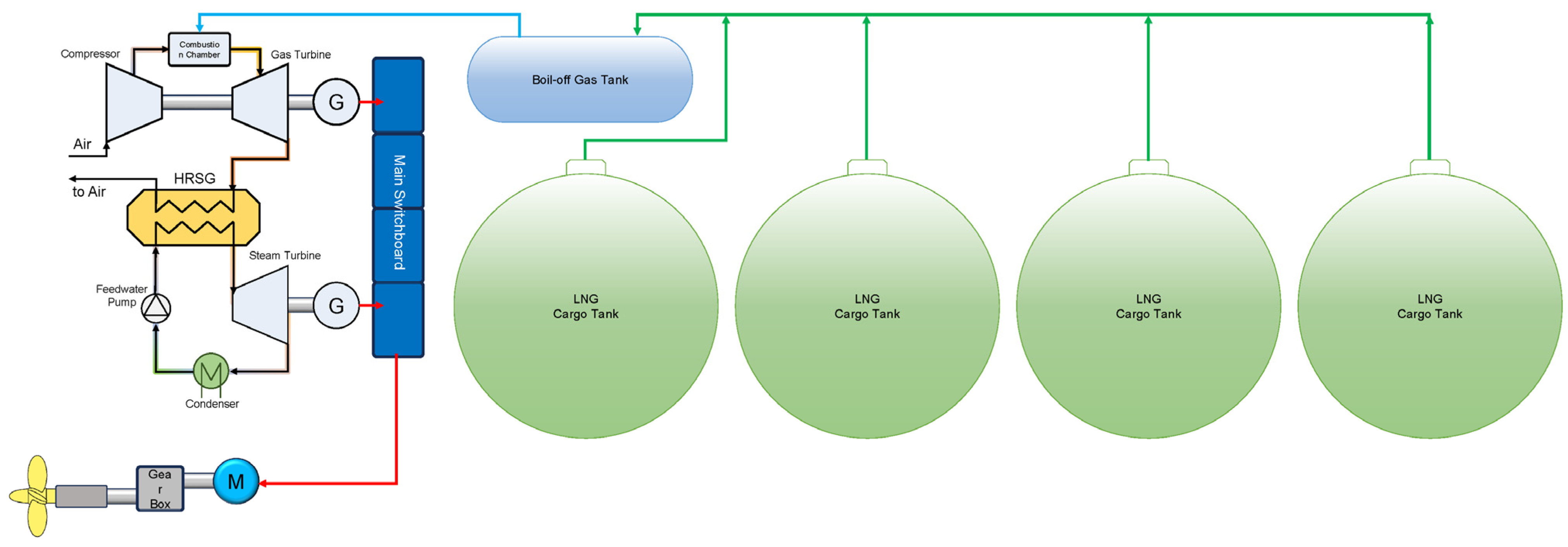
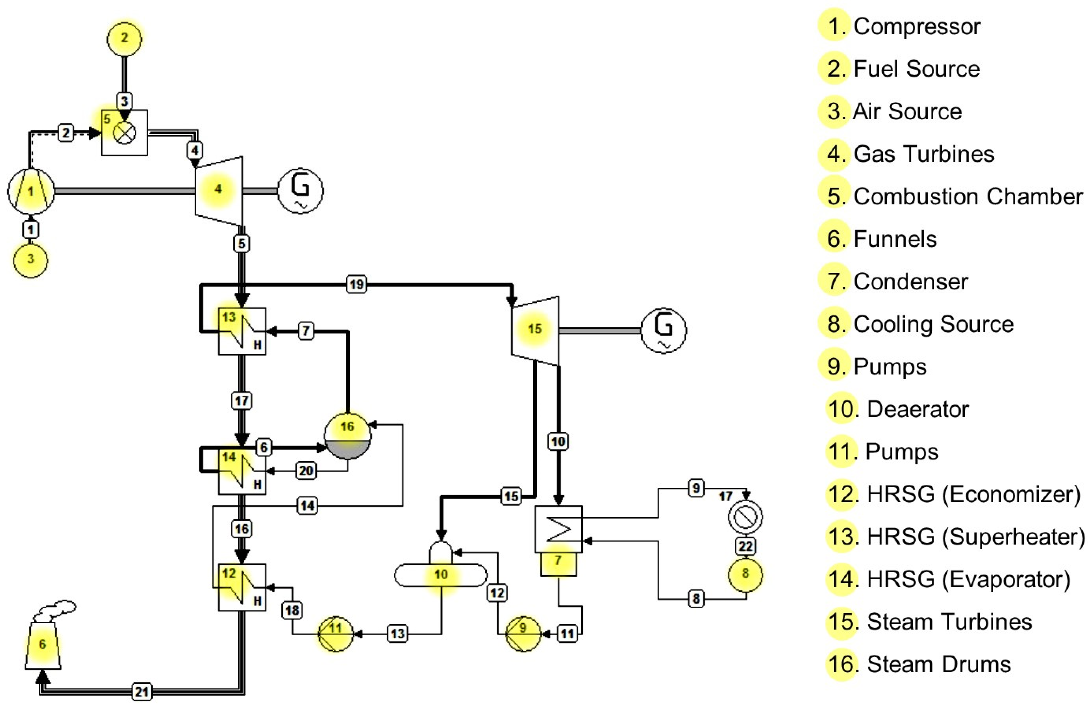
2.2. Design of COGES Propulsion System

The design of a ship’s propulsion system starts from power requirements based on ship speed, determining the parameters and components of the combined gas turbine and steam turbine integrated electric drive system. The COGES system proposed in this research is shown in Figure 4. In this COGES system, the fuel is assumed to come from 100% boil-off gas produced from the LNG cargo tank. The use of boil-off gas as ship fuel makes this system more economical in terms of operations and saves more space on the ship compared to systems that still use diesel engines, both conventional diesel engines and dual-fuel diesel electric (DFDE) propulsion systems. However, in actual conditions, to meet the ship’s overall electricity needs, additional auxiliary engines are still needed. This aims to be a safety factor as a source of backup energy for ships.
The fuel used in designing this propulsion system is natural gas that comes from boil-off gas from the LNG cargo being transported. The natural gas load transported has a CH4 composition of 91.2% and a lower heating value of 49,426.97 kJ/kg. Gas boil-off (BoG) is calculated using Equation (1).
B o G = V × ρ × B O R × t 24
where V is the LNG cargo volume (m3), ρ is the LNG density (kg/m3), BOR is the boil-off rate (%/day), and t is the shipping time (hours). The gas turbine used in this system has a power specification of 100% load of 5.4 MW, the fuel is natural gas, the exhaust gas temperature (100% load) is 494 °C, the pressure ratio is 13.9, and the exhaust mass flow is 21.3 kg/s. The selection of this gas turbine is based on the total electric load balance requirements of the ship design, as well as considerations of its availability in the market. The steam turbine specifications have an inlet steam pressure of 25 bar, a maximum inlet temperature of 510 °C, and a maximum output of 5000 kW.
In the COGES design used, the heat recovery steam generator (HRSG) used is composed of three components, namely, a superheater, evaporator, and economizer. The working process of these three components becomes a single HRSG operation where the economizer is useful as an initial heater to raise the temperature of the working fluid again from the fluid phase to the saturated liquid phase. Later, the working fluid is processed in the evaporator to become a saturated vapor phase and reheated in the superheater to heat the water in the boiler. The parameter value used in the simulation for the superheater component (ΔThi) is 30 °C and the evaporator (ΔTpinchpoint) is 25 °C.
The main system-supporting components consist of a boiler feed pump with maximum head specifications of 1200 m, capacity of 70 m3/h, and isentropic efficiency of 85%. The deaerator component has a capacity specification of 14,000 lbs/h and the inlet pressure (Pin) is 2 bar. The other supporting components are a pump with an isentropic efficiency of 85%, a condenser assumed to have a pressure drop of 0.1 Bar, and a generator with a mechanical efficiency of 90%.

2.3. Thermodynamic Analysis of Designed System

The thermodynamic cycle used in the design of the COGES propulsion system is a combination system between the Brayton cycle and the Rankine cycle. The combined cycle aims to have a higher thermal efficiency value than the cycles used separately. This is possible because gas turbines generally operate at higher temperatures than steam turbine cycles. Thermodynamic analysis of this system uses Cycle-Tempo version 5.1 software and tools program to design, analyze, optimize, and monitor the thermodynamics of the energy system [49].
The thermodynamic analysis scheme of the proposed COGES system is shown in Figure 5. The COGES propulsion system design begins with a gas turbine system where air from the environment enters through the air source at number 3, which is then compressed by compressor number 1 to increase the pressure. Then, the compressed air enters combustion chamber number 5 to be mixed with fuel, namely, natural gas, producing pressurized hot gas to drive gas turbine number 4 to produce energy. Gas turbine number 4 has also been coupled with a generator to produce the required electrical power. The gas produced from the turbine, or what could be called flue gas, exits the gas turbine system through pipe number 5 and is used for the following cycle process.
The following essential component in the propulsion system of this design is the heat recovery steam generator, which is an advanced component where the exhaust gas from the turbine is used in the next cycle. This component is the energy source in the steam turbine cycle. This component consists of several heat exchangers that function as superheaters, evaporators, and economizers. Thus, the gas turbine exhaust gas is utilized in stages, starting from the exhaust gas with the highest temperature of around 494 °C, which heats the saturated steam in the superheater. Then the exhaust gas, whose temperature has been reduced to around 444 °C, changes the working fluid phase to steam in the evaporator. The exhaust gas is then used to heat the working fluid that comes from the condenser in the heat exchanger, which acts as an economizer.
Thermodynamic analysis of the gas turbine combination cycle was carried out to determine the power produced by the design system and whether it can meet the ship’s propulsion power requirements. The input values and thermodynamic equations for each system are shown in Table 2.
The power produced by the COGES system (Woverall) is a combination of the total power between the gas turbine cycle and the steam turbine cycle using Equation (2) and the overall system efficiency (ηoverall) using Equation (3).
Woverall = WGas Turbine + WSteam Turbine
η o v e r a l l =   W G a s   T u r b i n e + W S t e a m   T u r b i n e         Q i n
Then, to find out the Qin value, which is the product of the gas fuel mass flow rate and the lower heating value (LHV) of the fuel, the Qin calculation uses Equation (4). Thus, the value of the system’s overall efficiency is designed using Equation (5).
Qin = mfuel × LHV
η o v e r a l l =   W G a s   T u r b i n e   + W S t e a m   T u r b i n e         m i n × L H V

2.4. Environmental Impact Assessment

The method used in environmental impact assessment is eco-indicator 99. By using this method, the environmental impact is expressed in eco-indicator points per unit time (Pts/s or mPts/s). The value of 1 Pt (one point) represents one thousandth of the environmental burden per year of a European resident. Apart from that, the environmental impact can also be in units of kgCO2 per unit of product produced by the system, because CO2 is a greenhouse gas that has an effect on climate change. Environmental impact assessment is obtained by conducting an emission factor analysis, which uses an approach based on international standards (ISO 14004). With the eco-indicator method, evaluations can be carried out for materials, production processes, transportation processes, energy generation processes, and disposal scenarios. This method is also used to identify each component in the system that has a high environmental impact. Then the effects of environmental impacts are also divided into three categories of damage, including human health, ecosystem quality, and resources. The impact on human health (human health) is in units of DALY (disability-adjusted life years), where 1 DALY is one year of healthy life lost by a person. The impact of environmental ecosystems (ecosystems quality) has PDFm2yr units (potentially disappeared fraction of species per square meter year); 1 PDFm2yr means damage to species or ecosystems covering an area of 1 m2 in one year. The impact of resources has MJ surplus units, where 1 MJ surplus is the basic amount of energy needed to extract a natural resource.
The analysis of greenhouse gas emissions such as CO2, CH4, and NO2 in the designed propulsion system is intended to determine the estimated amount of emissions produced. The analysis is carried out using the tier method, which uses emission factors to fuel consumption data. Analysis using this tier method uses Equation (6).
E G H G = ( F C × E C )
where FC is the fuel consumed for each fuel type, such as diesel, gasoline, or gas, while EF is the emission factor from the fuel type used for the ship engine. The values used for calculations include CO2 emission factors for natural gas of 56,100 kg/TJ and fuel consumption for bulk liquid vessels of 14,685 + 0.00079GRT. Then, based on the data that were obtained from the previous discussion, the data are simulated using SimaPro software to obtain an emission analysis using the eco-indicator 99 (H) life-cycle assessment (LCA) method. Then the results of the damage assessment are obtained in several categories such as ecosystems quality, resorts, human events, and climate change. From the results of the damage assessment obtained from the simulation, an analysis is carried out to compare the output emissions produced by the COGES propulsion system with other propulsion systems, such as the diesel propulsion system or the DFDE system.

2.5. Techno-Economic Analysis

The economic theory used to build a propulsion system for ships, especially the COGES combination propulsion system for small LNG carrier 7500 m3 ships, in this research is to use several aspects of an economic approach, namely, net present value (NPV) in Equation (7), internal rate of return (IRR) in Equation (8), and payback period (PBP) in Equation (9).
N P V = t = 0 T X t ( 1 + i ) t
I R R = t = 0 T X t ( 1 + R O R ) t
P B P = t = 0 t = P O T X t = 0
To obtain the above economic values, it is necessary to take into account the capital costs (CAPEX) and operating costs (OPEX). CAPEX in this research focuses on the cost of the design of propulsion system components. The propulsion system proposed in this research is the COGES system, which consists of a gas turbine, steam turbine, HRSG, boiler pump, boiler, condenser, deaerator, and cooling pump. Each component’s capital cost uses assumptions based on open study reports and market prices [50]. The cost for each component of the proposed propulsion system is shown in Table 3. OPEX is the operational costs incurred during one year of operation, which consist of fuel costs, fresh water, maintenance costs, lubricating oil, and overhead costs. This study will estimate operating costs according to existing conditions in the field from various sources. Because the proposed propulsion system uses BoG as gas turbine fuel, fuel costs for diesel oil are eliminated.
To calculate the economic feasibility of the proposed system, it is assumed that income comes from ship charters. The ship is an LNG carrier-type ship, which functions as a charter ship that delivers LNG from resources to places closer to consumers. The type of charter used in this study involves the party carrying out ship operations being the ship owner with a time charter type. According to LNG ship charter rate data from LNG industry sources, the daily charter costs for LNG carrier ships vary greatly, namely, 36,038 USD/day in 2015 and 89,200 USD/day in 2021 [52,53]. This study used several variations of the charter rate to assess whether the proposed propulsion system is feasible. The charter rate variations used are 30,000–70,000 USD/day.

3. Results and Discussion

3.1. Performance of COGES System

Performance analysis of the combined gas turbine cycle propulsion system was conducted to determine the amount of power that can be generated by the design system and whether it can meet the ship’s propulsion power needs, as previously calculated. Then, for system performance analysis, Cycle-Tempo applications were used to determine the value of the thermodynamic input in the design system, so that the power output of the combined gas-steam turbine system in this design could be determined. The thermodynamic results obtained at 100% fuel load are shown in Table 4. Based on the simulation results of the COGES system, the total power produced reached 8369 kW under 100% loading conditions.
Based on the results shown in Figure 6, it is obtained that the minimum requirement for the ship to be able to move at a service speed of 12 knots is 1832 kW; using COGES, the system needs to work at 24% loading conditions. Meanwhile, if the ship is going to move at its maximum design speed of 14 knots, the required power is 3377 kW using a COGES combination design system at 44% loading conditions. Based on thermodynamic simulation data, the overall efficiency of the COGES system was calculated using Equation (5), resulting in a maximum efficiency of the system is 30.1%. This aligns with the practical operation of low-power-range power plants, where efficiencies typically range from 25% to 35% [54,55]. From these results, the COGES designed propulsion system can produce greater output power than commonly used factory engines such as diesel engines or dual-fuel engines. The COGES system can produce power output in the range of 15 kWh at a heat input of 50,000 kJ to 42.6 kWh at an input of 150,000 kJ. Meanwhile, the diesel and DFDE engines produce a power output of around 6 kWh at an input of 50,000 kJ to 20 kWh at an input of 150,000 kJ.
The system running condition depends on fuel availability, namely, boil-off gas produced from the LNG cargo tank. Figure 7 shows the boil-off gas produced with a boil-off rate variation of 0.1–0.3% of the LNG cargo capacity at each ship speed. The boil-off rate of the LNG generally ranges from 0.1% to 0.15%/day for large LNG vessels, while small LNG vessels have a high boil-off rate of between 0.2% and 0.6%/day, depending on the type of tank and the amount of heat introduced [56,57]. The design propulsion system requirements are based on fuel availability; it was found that the design propulsion system using combined gas–steam can meet its needs under conditions of a gas boil-off rate of 0.3%/day at a service speed of 12 knots with a need of 69.5 m3 and availability of 71.6 m3 to cover the route cruise according to a plan for 3 days of travel. In conditions of a gas boil-off rate of 0.25%/day, the ship can sail at a constant speed of 11 knots, with the ship’s boil-off gas availability still experiencing a positive margin with an availability of 65.1 m3 with a requirement of 55.9 m3. In conditions of a gas boil-off rate of 0.2%/day, the ship can sail at a constant speed of 10 knots, with the ship’s boil-off gas availability still experiencing a positive margin with an availability of 57.3 m3 with a requirement of 45.1 m3. With a gas boil-off rate of 0.15%/day, the ship can sail at a constant speed of 9 knots with the availability of boil-off gas. The ship still experiences a positive margin with an availability of 47.7 m3 and a need of 36.3 m3. Then, in the condition of a gas boil-off rate of 0.1%/day, the ship can sail at a constant speed of 8 knots with the availability of boil-off gas; the ship still experiences a positive margin with an availability of 35.8 m3 with a requirement of 28.7 m3. The relationship between the availability of boil-off gas fuel is that the faster the ship sails, the shorter the travel time will be, so the availability of boil-off gas will also be less. Still, the system requirements will be more significant by increasing the existing speed.

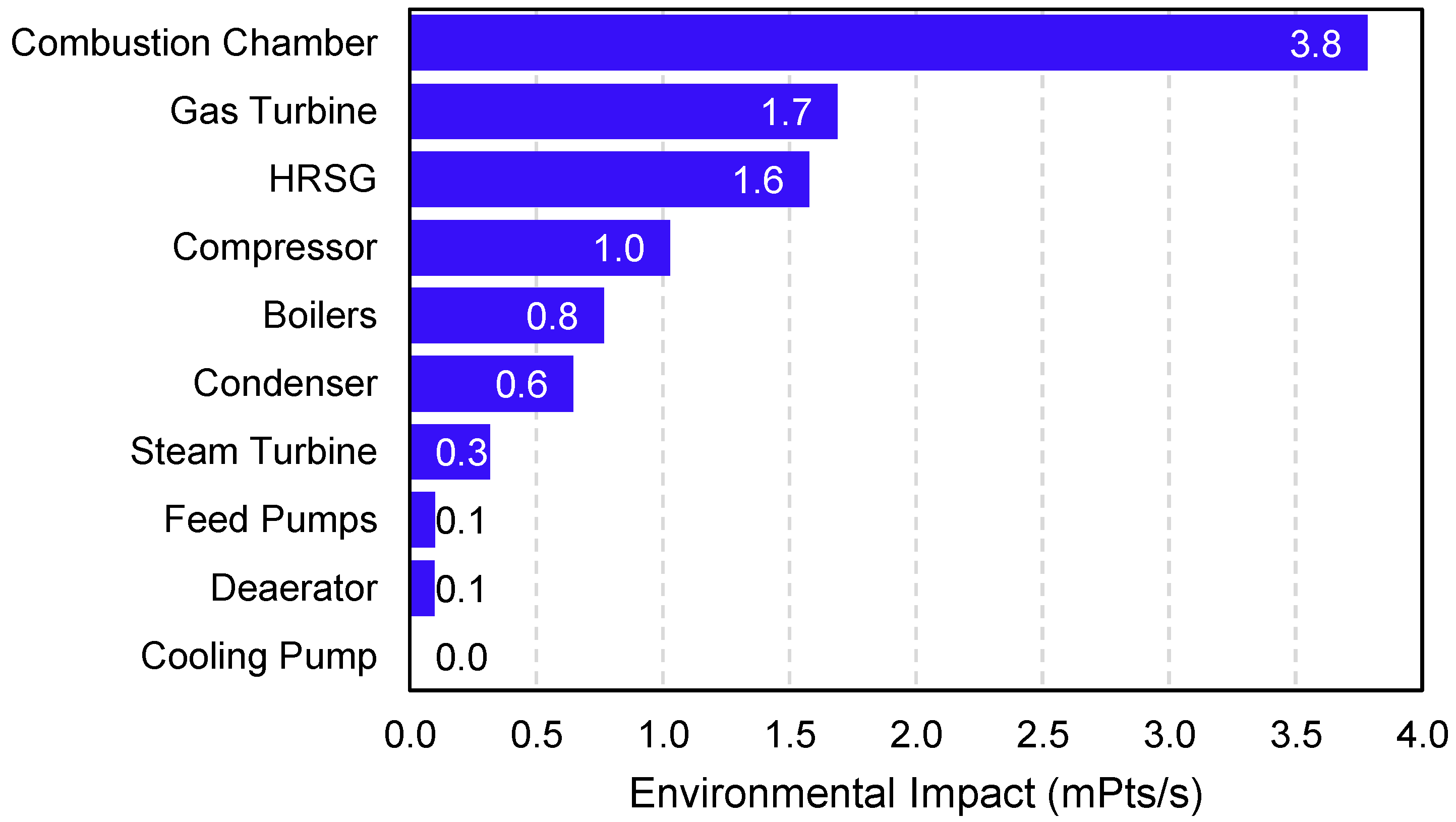
3.2. Analysis of the Environmental Impact of the System

The system’s environmental impact was analyzed using the SimaPro software emission simulation application, which aims to obtain the results of emissions released by the designed propulsion system and the comparative propulsion system. Simulations using the SimaPro application were carried out using the IPCC 2013 GWP 100a method, which is a method based on data published by the Intergovernmental Panel on Climate Change that was chosen to provide assessment results for greenhouse gas emissions produced by a cycle in kilograms of CO2 with global warming potential for the next 100 years front. Referring to the input and output of each component in the COGES system, each component influences the environment, which can be transmitted into an eco-indicator by calculating the total emissions produced by each component. Processing data for each component produces eco-indicators that impact the human health, ecosystem, and resources in the form of PTS, which indicates a representation of the annual environmental load, as seen in Table 5. Then the results of the eco-indicator data are processed to obtain the value of the environmental impact caused by the system in mPts/s units, which is shown in Figure 8.
In this research, carbon emissions were also investigated for the entire system compared to commonly used engines such as diesel or DFDE. The emission calculation parameters are limited to each system’s CO2 gas emissions and damage assessment. The results of comparing emissions and damage assessments for each system are shown in Table 6. The results of the environmental impact analysis show that the COGES system has the most negligible impact on the environment compared to the diesel propulsion system and the DFDE propulsion system. This can happen because the COGES system only uses natural gas as fuel and does not use any other fossil fuels. This makes the COGES propulsion system more environmentally friendly. From the LCA simulation, it show the climate change contribution of the COGES propulsion system is 0.149 kgCO2 equivalents, compared to the contribution of the diesel propulsion system of 0.314 kgCO2 equivalents and the DFDE system of 0.155 kg CO2 equivalents. Although not wholly zero-emissions, COGES systems produce relatively lower emissions than conventional diesel engines. Higher efficiency and cleaner fuel can reduce carbon dioxide (CO2) and nitrogen oxide (NOx) emissions [58]. The COGES system does not rely on combustion like diesel and DFDE systems, which can lead to lower methane emissions, a potent greenhouse gas [59]. This is in line with other research; from direct measurements on LNG carrier ships, it was found that CO2 emissions from using gas fuel were lower compared to conventional diesel engines [60].
Apart from the results of CO2 emissions, a comparison of environmental impacts was obtained using the eco-indicator 99 (H) method. Where environmental impacts affect health, ecosystem quality, and resources for a power output of 1 kWh, the result is that the COGES system has the most negligible influence on damage for the three existing categories. In the health category, only 0.755 × 10⁻⁷ DALY or around 2.2 s of healthy life is lost by a person to produce 1 kWh, while the diesel system affects 4.61 × 10⁻⁷ DALY or around 14.5 s of healthy life per 1 kWh and the DFDE system affect 1.64 × 10⁻⁷ DALYs or around 5.2 s of healthy life per 1 kWh.

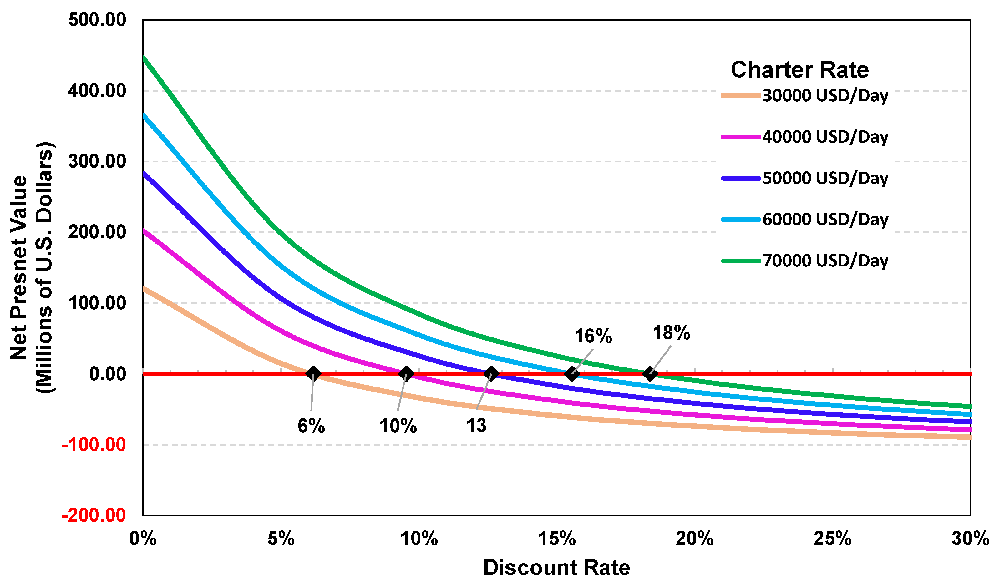
3.3. Economic Feasibility of COGES System

The economic feasibility results of the proposed propulsion system are shown in Table 7. Based on the results of the economic study, it can be seen that the ship’s charter rate costs greatly influence the NPV value. The COGES system is economically feasible if the minimum charter rate is 50,000 USD/day. With this charter rate, a positive NPV value of around 25 million USD is obtained with an IRR of 12.6% with a payback period of 8 years of operation. With a charter rate of 50,000 USD/day, it is assumed that the profits obtained can exceed the capital costs incurred for the proposed propulsion system during the specified payback period. The estimated capital costs were shown in the previous section in Table 3. With the charter rate variations shown in Table 4, to obtain a positive NPV value, a minimum charter rate of 50,000 USD/day is required. A positive NPV means that the proposed system produces a more significant present value than the initial investment, indicating that the investment can provide good financial returns.
The results of the economic feasibility study are analyzed further to obtain recommendations for the maximum value of the discount rate if the investment is made based on the rate of return used to calculate the present value. Figure 9 shows the NPV and discount rate values with variations in the charter rate. To assess whether a proposed system investment is feasible or not, the IRR of a system must be higher than the discount rate; then, the system is considered feasible because the rate of return generated is greater than the discount rate used. From these results, it is found that for the proposed system to be economically feasible, the discount rate value cannot be greater than 13% for a charter rate of 50,000 USD/day. Determining the discount rate for investment, including investment in LNG vessels, includes system risks, LNG market conditions, the life cycle of LNG vessels, and regulations, including government policy. The risk level of the LNG ship system affects the discount rate. If a system has a high level of risk, investors may expect a higher rate of return to compensate for that risk. In general, systems with higher risk require a more significant discount rate to reflect the higher level of risk.

4. Conclusions

In this research, a techno-economic study of the COGES system of LNG carriers was carried out. The study was carried out using a case study of an LNG ship with a capacity of 7500 m3 with a power requirement at an average speed of 12 knots of 1832 kW. The design of the proposed COGES propulsion system consists of three main parts, namely, the gas turbine, HRSG, and steam turbine, which utilizes boil-off gas as the primary fuel. Based on the results of thermodynamic analysis, the COGES system obtains a total system efficiency of 30.1%, which can achieve the desired power output. An environmental impact assessment compared the life cycle with that of commonly used propulsion systems. The climate change from the COGES propulsion system contribute 0.149 kgCO2 equivalents compared to the contribution of the diesel propulsion system of 0.314 kgCO2 equivalents and the DFDE system of 0.155 kgCO2 equivalents. The latest study carried out an economic study with variations in the charter rate value of LNG ships; it was found that the COGES system is economically feasible if the minimum charter rate is 50,000 USD/day. A positive NPV value of around 25 million USD is obtained with an IRR of 12.6% with a payback period of 8 years of operation. From these results, it can be concluded that the COGES system is feasible from the aspects of performance, environment, and investment, so this system can be used as a convincing alternative for future propulsion systems. The findings support prior studies indicating that the COGES system yields reduced emissions. While not completely emission-free, COGES demonstrates comparatively lower emissions than traditional diesel engines. Enhanced efficiency and the adoption of cleaner fuels contribute to a reduction in carbon emissions, thereby mitigating the environmental footprint of maritime shipping.

Author Contributions

Conceptualization, M.A.B.; methodology, M.A.B. and S.A.Z.; software, S.A.Z.; validation, M.A.B., R.A. and G.T.; formal analysis, M.A.B., G.L.P., A.R., A.H.M. and R.A.; investigation, M.A.B., G.L.P. and A.R.; resources, G.L.P.; data curation, A.R.; writing—original draft preparation, M.A.B. and S.A.Z.; writing—review and editing; M.A.B. and G.T.; funding acquisition, M.A.B. All authors have read and agreed to the published version of the manuscript.

Funding

Q1 International Indexed Publication (PUTI) Grant for Fiscal Year 2023–2024 Number NKB-533/UN2.RST/HKP.05.00/2023 Universitas Indonesia.

Data Availability Statement

Data is unavailable due to privacy.

Acknowledgments

The authors express great appreciation to the Directorate of Research and Development at the Universitas Indonesia.

Conflicts of Interest

The authors declare no conflict of interest.

References

  1. International Maritime Organization (IMO). Initial Imo Strategy on Reduction of Ghg Emissions from Ships; International Maritime Organization (IMO): London, UK, 2018. [Google Scholar]
  2. Joung, T.-H.; Kang, S.-G.; Lee, J.-K.; Ahn, J. The IMO initial strategy for reducing Greenhouse Gas (GHG) emissions, and its follow-up actions towards 2050. J. Int. Marit. Safety Environ. Aff. Shipp. 2020, 4, 1–7. [Google Scholar] [CrossRef]
  3. Mallouppas, G.; Yfantis, E.A. Decarbonization in Shipping Industry: A Review of Research, Technology Development, and Innovation Proposals. J. Mar. Sci. Eng. 2021, 9, 415. [Google Scholar] [CrossRef]
  4. Nuchturee, C.; Li, T.; Xia, H. Energy efficiency of integrated electric propulsion for ships—A review. Renew. Sustain. Energy Rev. 2020, 134, 110145. [Google Scholar] [CrossRef]
  5. Dotto, A.; Campora, U.; Satta, F. Feasibility study of an integrated COGES-DF engine power plant in LNG propulsion for a cruise-ferry. Energy Convers. Manag. 2021, 245, 114602. [Google Scholar] [CrossRef]
  6. Merz, C.A.; Pakula, T.J. The Design and Operational Characteristics of a Combined Cycle Marine Powerplant. In Proceedings of the ASME Turbo Expo, Montreal, QC, Canada, 15–19 June 2015. [Google Scholar]
  7. Haglind, F. A review on the use of gas and steam turbine combined cycles as prime movers for large ships. Part II: Previous work and implications. Energy Convers. Manag. 2008, 49, 3468–3475. [Google Scholar] [CrossRef]
  8. Packalén, S.; Karlsson Nord, N. Combined Gas- and Steam Turbine as Prime Mover in Marine Applications; Department of Shipping and Marine Technology, Chalmers University of Technology: Gothenburg, Sweden, 2017. [Google Scholar]
  9. Alzayedi, A.M.T.; Sampath, S.; Pilidis, P. Techno-Environmental Evaluation of a Liquefied Natural Gas-Fuelled Combined Gas Turbine with Steam Cycles for Large Container Ship Propulsion Systems. Energies 2022, 15, 1764. [Google Scholar] [CrossRef]
  10. Pereira, S.; Almeida, P. Energy Assessment and Comparison of the Use of a Conventional Steam Turbine System in a Lng Carrier Propulsion with the Use of a Coges System. SSRN Electron. J. 2022. [Google Scholar] [CrossRef]
  11. LNGreen: Next-Generation LNG Carrier Concept by DNV GL, HHI, GTT and GasLog n.d. Available online: https://www.dnv.com/news/lngreen-next-generation-lng-carrier-concept-by-dnv-gl-hhi-gtt-and-gaslog-30420 (accessed on 6 December 2023).
  12. Pamitran, A.S.; Budiyanto, M.A.; Dandy Yusuf Maynardi, R. Analysis of ISO-tank wall physical exergy characteristic—Case study of LNG boil-off rate from retrofitted dual fuel engine conversion. Evergreen 2019, 6, 134–142. [Google Scholar] [CrossRef]
  13. Al-Kubaisi, A. An Insight into the World’s Largest LNG Ships. In Proceedings of the International Petroleum Technology Conference, Kuala Lumpur, Malaysia, 3–5 December 2008. [Google Scholar] [CrossRef]
  14. Wibisana, L.P.; Budiyanto, M.A. Design and Cost Multi-Objective Optimization of Small-Scale LNG Carriers using the Value Engineering Approach. Int. J. Technol. 2021, 12, 1288–1301. [Google Scholar] [CrossRef]
  15. Budiyanto, M.A.; Singgih, I.K.; Riadi, A.; Putra, G.L. Study on the LNG distribution to Mobile Power Plants using a Small-Scale LNG Carrier for the case of the Sulawesi region of Indonesia. Energy Rep. 2022, 8, 374–380. [Google Scholar] [CrossRef]
  16. Yin, L.; Ju, Y. Review on the design and optimization of BOG re-liquefaction process in LNG ship. Energy 2022, 244, 123065. [Google Scholar] [CrossRef]
  17. Qu, Y.; Noba, I.; Xu, X.; Privat, R.; Jaubert, J.-N. A thermal and thermodynamic code for the computation of Boil-Off Gas—Industrial applications of LNG carrier. Cryogenics 2019, 99, 105–113. [Google Scholar] [CrossRef]
  18. Ferrín, J.L.; Pérez-Pérez, L.J. Numerical simulation of natural convection and boil-off in a small size pressurized LNG storage tank. Comput. Chem. Eng. 2020, 138, 106840. [Google Scholar] [CrossRef]
  19. Gerasimov, V.E.; Kuz’Menko, I.F.; Peredel’Skii, V.A.; Darbinyan, R.V. Introduction of technologies and equipment for production, storage, transportation, and use of LNG. Chem. Pet. Eng. 2004, 40, 31–35. [Google Scholar] [CrossRef]
  20. Budiyanto, M.A.; Riadi, A.; Buana, I.G.N.S.; Kurnia, G. Study on the LNG distribution to mobile power plants utilizing small-scale LNG carriers. Heliyon 2020, 6, e04538. [Google Scholar] [CrossRef] [PubMed]
  21. APEC. Study on Optimal Use of Small-Scale Shallow-Draft LNG Carriers and FSRUs in the APEC Region APEC Energy Working Group. 2020. Available online: https://www.apec.org/docs/default-source/publications/2020/4/study-on-optimal-use-of-small-scale-shallow-draft-lng-carriers-and-fsrus-in-the-apec-region/220_ewg_study-on-optimal-use-of-small-scale-shallow-draft-lng-carriers-and-fsrus-in-the-apec-region.pdf (accessed on 21 December 2023).
  22. Budiyanto, M.A.; Pamitran, A.S.; Yusman, T. Optimization of the Route of Distribution of LNG using Small Scale LNG Carrier: A Case Study of a Gas Power Plant in the Sumatra Region, Indonesia. Int. J. Energy Econ. Policy 2019, 9, 179–187. [Google Scholar] [CrossRef]
  23. Hongjun, F.; Lei, W.; Bo, Z.; Enshaei, H.; Jiaolong, C. A study on design optimization of LNG power system onboard a dual fueled platform supply vessel. In Proceedings of the 2nd International Conference on Smart & Green Technology for Shipping and Maritime Industries, Glasgow, Scotland, 11–12 July 2019; Available online: https://hdl.handle.net/102.100.100/522683 (accessed on 21 December 2023).
  24. Boretti, A. Advantages and Disadvantages of Diesel Single and Dual-Fuel Engines. Front. Mech. Eng. 2019, 5, 493925. [Google Scholar] [CrossRef]
  25. Budiyanto, M.A.; Nasruddin; Nawara, R. The optimization of exergoenvironmental factors in the combined gas turbine cycle and carbon dioxide cascade to generate power in LNG tanker ship. Energy Convers. Manag. 2020, 205, 112468. [Google Scholar] [CrossRef]
  26. Cwilewicz, R.; Górski, Z. Prognosis of marine propulsion plants development in view of new requirements concerning marine fuels. J. Kones 2014, 21, 61–68. [Google Scholar] [CrossRef]
  27. Dotto, A.; Sacchi, R.; Satta, F.; Campora, U. Dynamic performance simulation of combined gas electric and steam power plants for cruise-ferry ships. Next Energy 2023, 1, 100020. [Google Scholar] [CrossRef]
  28. Fernández, I.A.; Gómez, M.R.; Gómez, J.R.; Insua, B. Review of propulsion systems on LNG carriers. Renew. Sustain. Energy Rev. 2017, 67, 1395–1411. [Google Scholar] [CrossRef]
  29. Tadros, M.; Ventura, M.; Guedes Soares, C. A nonlinear optimization tool to simulate a marine propulsion system for ship conceptual design. Ocean Eng. 2020, 210, 107417. [Google Scholar] [CrossRef]
  30. Inal, O.B.; Charpentier, J.F.; Deniz, C. Hybrid power and propulsion systems for ships: Current status and future challenges. Renew. Sustain. Energy Rev. 2021, 156, 111965. [Google Scholar] [CrossRef]
  31. Kurz, R. Parameter Optimization on Combined Gas Turbine-Fuel Cell Power Plants. J. Fuel Cell Sci. Technol. 2005, 2, 268–273. [Google Scholar] [CrossRef]
  32. Sulligoi, G.; Vicenzutti, A.; Menis, R. All-electric ship design: From electrical propulsion to integrated electrical and electronic power systems. IEEE Trans. Transp. Electrif. 2016, 2, 507–521. [Google Scholar] [CrossRef]
  33. Pamik, M.; Nuran, M. The historical process of the diesel electric propulsion system. Dokuz Eylül Üniversitesi Denizcilik Fakültesi Derg. 2021, 13, 299–316. [Google Scholar] [CrossRef]
  34. Ahmadi, G.; Jahangiri, A.; Toghraie, D. Design of heat recovery steam generator (HRSG) and selection of gas turbine based on energy, exergy, exergoeconomic, and exergo-environmental prospects. Process. Saf. Environ. Prot. 2023, 172, 353–368. [Google Scholar] [CrossRef]
  35. Nirbito, W.; Budiyanto, M.A.; Muliadi, R. Performance Analysis of Combined Cycle with Air Breathing Derivative Gas Turbine, Heat Recovery Steam Generator, and Steam Turbine as LNG Tanker Main Engine Propulsion System. J. Mar. Sci. Eng. 2020, 8, 726. [Google Scholar] [CrossRef]
  36. Huan, T.; Hongjun, F.; Wei, L.; Guoqiang, Z. Options and Evaluations on Propulsion Systems of LNG Carriers. In Propulsion Systems; IntechOpen: London, UK, 2019. [Google Scholar] [CrossRef]
  37. Lombardi, L.; Carnevale, E.; Corti, A. A review of technologies and performances of thermal treatment systems for energy recovery from waste. Waste Manag. 2015, 37, 26–44. [Google Scholar] [CrossRef] [PubMed]
  38. Singh, D.V.; Pedersen, E. A review of waste heat recovery technologies for maritime applications. Energy Convers. Manag. 2016, 111, 315–328. [Google Scholar] [CrossRef]
  39. Díaz-Secades, L.A.; González, R.; Rivera, N.; Montañés, E.; Quevedo, J.R. Waste heat recovery system for marine engines optimized through a preference learning rank function embedded into a Bayesian optimizer. Ocean Eng. 2023, 281, 114747. [Google Scholar] [CrossRef]
  40. Larsen, U.; Sigthorsson, O.; Haglind, F. A comparison of advanced heat recovery power cycles in a combined cycle for large ships. Energy 2014, 74, 260–268. [Google Scholar] [CrossRef]
  41. Ouyang, T.; Zhao, Z.; Lu, J.; Su, Z.; Li, J.; Huang, H. Waste heat cascade utilisation of solid oxide fuel cell for marine applications. J. Clean. Prod. 2020, 275, 124133. [Google Scholar] [CrossRef]
  42. Theotokatos, G.; Livanos, G. Techno-economical analysis of single pressure exhaust gas waste heat recovery systems in marine propulsion plants. Proc. Inst. Mech. Eng. Part M J. Eng. Marit. Environ. 2012, 227, 83–97. [Google Scholar] [CrossRef]
  43. Buonomano, A.; Del Papa, G.; Francesco Giuzio, G.; Maka, R.; Palombo, A. Advancing sustainability in the maritime sector: Energy design and optimization of large ships through information modelling and dynamic simulation. Appl. Therm. Eng. 2023, 235, 121359. [Google Scholar] [CrossRef]
  44. Çolak, K.; Ölmez, H.; Saraç, B. Waste heat recovery assessment of triple heat-exchanger usage for ship main engine pre-heating and fresh water generation systems. Proc. Inst. Mech. Eng. Part M J. Eng. Marit. Environ. 2023, 238, 209–230. [Google Scholar] [CrossRef]
  45. Benvenuto, G.; Trucco, A.; Campora, U. Optimization of waste heat recovery from the exhaust gas of marine diesel engines. Proc. Inst. Mech. Eng. Part M J. Eng. Marit. Environ. 2014, 230, 83–94. [Google Scholar] [CrossRef]
  46. Altosole, M.; Benvenuto, G.; Campora, U.; Laviola, M.; Trucco, A. Waste Heat Recovery from Marine Gas Turbines and Diesel Engines. Energies 2017, 10, 718. [Google Scholar] [CrossRef]
  47. Saidur, R.; Rezaei, M.; Muzammil, W.K.; Hassan, M.H.; Paria, S.; Hasanuzzaman, M. Technologies to recover exhaust heat from internal combustion engines. Renew. Sustain. Energy Rev. 2012, 16, 5649–5659. [Google Scholar] [CrossRef]
  48. Farhat, O.; Faraj, J.; Hachem, F.; Castelain, C.; Khaled, M. A recent review on waste heat recovery methodologies and applications: Comprehensive review, critical analysis and potential recommendations. Clean. Eng. Technol. 2022, 6, 100387. [Google Scholar] [CrossRef]
  49. Asimptote. Cycle-Tempo. n.d. Available online: https://asimptote.com/cycle-tempo/ (accessed on 31 January 2023).
  50. Japan International Cooperation Agency. Financial and Economical Analysis of New Power Plant. 2019. Available online: https://openjicareport.jica.go.jp/pdf/12119806_01.pdf (accessed on 21 December 2023).
  51. Japan International Cooperation Agency (JICA). Cost Estimation of the New Power Plant for Construction and Operation. 2004. Available online: https://openjicareport.jica.go.jp/pdf/11750742_19.pdf (accessed on 21 December 2023).
  52. Global LNG Shipping—ORders and Deliveries Report|Wood Mackenzie. n.d. Available online: https://www.woodmac.com/reports/lng-global-lng-shipping-orders-and-deliveries-58425985/ (accessed on 21 December 2023).
  53. LNG Tanker Average Spot Charter Rate 2021|Statista n.d. Available online: https://www.statista.com/statistics/1112660/lng-tanker-average-spot-charter-rate/ (accessed on 21 December 2023).
  54. Poullikkas, A. An overview of current and future sustainable gas turbine technologies. Renew. Sustain. Energy Rev. 2005, 9, 409–443. [Google Scholar] [CrossRef]
  55. Banihabib, R.; Assadi, M. The Role of Micro Gas Turbines in Energy Transition. Energies 2022, 15, 8084. [Google Scholar] [CrossRef]
  56. Harperscheidt, J. LNG as Fuel-Bunkering, Storage and Processing. 2003. Available online: https://www.stg-online.org/onTEAM/shipefficiency/programm/12-Harperscheidt_TGE.pdf (accessed on 21 December 2023).
  57. Kim, K.; Park, K.; Roh, G.; Chun, K. Case Study on Boil-Off Gas (BOG) Minimization for LNG Bunkering Vessel Using Energy Storage System (ESS). J. Mar. Sci. Eng. 2019, 7, 130. [Google Scholar] [CrossRef]
  58. Budiyanto, M.A.; Zidane, S.A.; Putra, G.L.; Riadi, A.; Andika, R.; Theotokatos, G. Performance Analysis of Combined Gas-Electric Steam Turbine System as Main Propulsion for Small-scale LNG Carrier Ships. Int. J. Technol. 2023, 14, 1093–1102. [Google Scholar] [CrossRef]
  59. Davidson, A.; Wait, N.; Desouza, C.; Marsh, D.; Green, D.; Andrews, P.; Chapman, S. Clean Air Gas Engine (CAGE): Reducing emissions by replacing diesel power in construction. High Speed Two (HS2) Infrastruct. Des. Constr. 2023, 4, 229–235. [Google Scholar] [CrossRef]
  60. Balcombe, P.; Heggo, D.A.; Harrison, M. Total Methane and CO2 Emissions from Liquefied Natural Gas Carrier Ships: The First Primary Measurements. Environ. Sci. Technol. 2022, 56, 9632–9640. [Google Scholar] [CrossRef]
Figure 1. Research stages on the techno-economics of the COGES propulsion system.
Energies 17 01415 g001
Figure 2. General arrangement of LNG carrier.
Energies 17 01415 g002
Figure 3. Power requirements of designed LNG carrier.
Energies 17 01415 g003
Figure 4. Proposed design of COGES propulsion system.
Energies 17 01415 g004
Figure 5. The thermodynamic analysis scheme of the proposed COGES system.
Energies 17 01415 g005
Figure 6. Power output of design propulsion system.
Energies 17 01415 g006
Figure 7. Boil-off gas production at certain ship speeds.
Energies 17 01415 g007
Figure 8. Environmental impact of each COGES component.
Energies 17 01415 g008
Figure 9. The NPV and discount rate values with variations in the charter rate.
Energies 17 01415 g009
Table 1. Principal dimensions of LNG carrier.
Principal ParametersDimensions
Length overall: 117.8 m
Length between perpendicular: 110.2 m
Beam: 18.6 m
Depth: 10.6 m
Draft: 7.15 m
Service speed: 12 knots
Cargo tank capacity: 7500 m3
Boil-off gas rate: 0.3%/day
Crew number: 19
Table 2. Parameter input of thermodynamic analysis.
CycleParameter Input Thermodynamic Equations
AmbientT = 298 K
P = 1.013 bar
Gas Turbine Cycle
1g—Compression
T = 298 K
P = 1.013 bar
mair = 21.3 kg/s
mfuel = 0.512 kg/s
T = T 1 g × ( P 2 P 1 ) k 1 k = 647 K
Wcompressor = m × C p × T × η s
Gas Turbine Cycle
2g—Combustion
P = 11.92 bar
h = 374 kJ/kg
Gas Turbine Cycle
3g—Expansion
P = 11.92 barT = T 4 g × ( P 3 P 4 ) k 1 k = 1373 K
Gas Turbine Cycle
4g—Heat Rejection
T = 767 K
P = 1.013 bar
Wgas turbine = m × C p × T × η s
Wactual = Wgas turbine − Wcompressor
Steam Turbine Cycle
1s—Water Feeding
T = 297 K
h = 100.5 kJ/kg
P = 1.0 bar
Wpump = v × P / η
Steam Turbine Cycle
2s—Pump Work Input
T = 302 K
h = 125.74 kJ/kg
mexhaust = 21.812 kg/s
Steam Turbine Cycle
3s—Heat Addition
T = 558 K
h = 1263.1 kJ/kg
P = 80 bar
Qexhaust = Qin, rankine
mexhaust. Cp. T = mfluid (h4 − h3)
Steam Turbine Cycle
4s—Heat Addition
T = 568 K
h = 2758.7 kJ/kg
Steam Turbine Cycle
5s—Work Output
T = 834 K
h = 3384 kJ/kg
Wactual = Wgas turbine − Wcompressor
Wturbine = mfluid (h5 − h6) − Wpump
Steam Turbine Cycle
6s—Heat Rejection
T = 302 K
h = 2555.6 kJ/kg
Table 3. Estimated cost for each component of the proposed propulsion system.
ComponentEstimated CostReference
Gas TurbineUSD 55,000,000.00 [51]
Steam TurbineUSD 18,000,000.00 [51]
HRSGUSD 26,000,000.00 [51]
GeneratorUSD 15,000,000.00 [51]
Hot Water Supply SystemUSD 7,000,000.00 [51]
CondenserUSD 80,000.00 [51]
DeaeratorUSD 800,000.00 [51]
Cooling PumpUSD 8000.00 [51]
Table 4. Results of system thermodynamics.
ComponentPower (kW)
Gas turbine air compressor7359.36
Gas turbine13,085.89
Actual gas turbine5726.53
Pump2.82
Steam turbine2645.52
Actual steam turbine2642.70
Total Combined Gas and Steam8369.23
Table 5. Eco-indicator results from each component of COGES system.
ComponentEco-Indicator (Pts)
EcosystemHealthSourceTotal
Compressor0.32610.5386396.8
Combustion Chamber1.238.914201460.1
Turbin Gas0.53517.3634651.8
HRSG0.516.2592608.7
Turbin Steam0.1013.26119122.4
Boiler0.2437.86288296.1
Deaerator0.03070.99336.437.4
Feed Pump0.03161.0237.438.4
Condenser0.2046.61242248.8
Cooling Pump0.00130.0431.581.62
Table 6. Comparison of emissions and damage assessments for COGES and other systems.
CategoryUnitCOGESDieselDFDE
Climate ChangekgCO2 equivalents0.1490.3140.155
Human HealthDALY0.755 × 10−74.61 × 10−71.64 × 10−7
Ecosystem QualityPDFm2yr0.001020.01530.00514
ResourceMJ surplus2.064.092.744
Table 7. Economic feasibility of COGES system.
Charter RateNet Present Value (NPV)Internal Rate Return (IRR)Payback Period (PBP)
30,000 USD/DayUSD 33,845,188.906.18%13 Years
40,000 USD/DayUSD 4,057,766.879.54%10 Years
50,000 USD/DayUSD 25,585,478.17 12.63%8 Years
60,000 USD/DayUSD 55,228,723.22 15.55%7 Years
70,000 USD/DayUSD 84,871,968.26 18.38%6 Years
Disclaimer/Publisher’s Note: The statements, opinions and data contained in all publications are solely those of the individual author(s) and contributor(s) and not of MDPI and/or the editor(s). MDPI and/or the editor(s) disclaim responsibility for any injury to people or property resulting from any ideas, methods, instructions or products referred to in the content.

