Abstract
The enhancement of energy systems in industrial zones is attracting the attention of researchers from all over the world. At the same time, optimization and advancement in heat recovery systems are now generating major interest in the energy sector. In this context, the present study suggests a new multiple heat recovery system should be applied to an industrial thermal peeling press machine. The new system consists of multiple sources of energy: the heat excess in the chimney, the exhaust gas of the chimney, and the exhaust gas of the boiler. To proceed with testing the potential of the suggested system, a hydraulic thermal peel press machine in the wood industry undergoes different tests to achieve the best configuration that will enable this machine to reach its operational temperature when heating. Five test configurations are proposed, designed, and applied experimentally on this machine. Many parameters were effective during the experimental tests, such as water flow rate, ambient air temperature, and initial water temperature. It was found that the application of the multiple heat recovery system increases the rate of heating from around 7 °C/min to around 13 °C/min. In terms of energy and economy, the “chimney + boiler only” configuration proved to be the best system to apply during the fall and winter seasons.
1. Introduction
1.1. Main Background
Current energy research is focused on reducing energy use and carbon dioxide emissions [1]. Significant energy consumption is essential for economic and social progress, with non-renewable fossil fuels being the primary source of this energy [2,3]. Nevertheless, about 50% of the energy used in industrial processes is dissipated as heat [4]. Moreover, buildings account for a substantial amount of the world’s energy consumption and waste heat generation [5]. There is a rising enthusiasm among individuals to reduce global energy use. The main reasons for this interest are the expensive nature of energy sources, the excessive release of harmful gasses, climate change, and the need for regulatory measures. Energy serves as a base for many applications and is currently the subject of millions of research studies [6,7,8]. The increasing frequency of human activities, subsequent industrial progress, globalization, and increased consumption have inexorably contributed to an unsettling rise in dangerous environmental pollutants that have the potential to impact the health of human beings [3,9,10]. The rapid depletion of fossil fuels and the growing concern over climate change have propelled the world towards a critical juncture in energy transition [11,12,13,14,15,16]. Both economic and social progress need massive energy consumption, much of which comes from non-renewable fossil fuels [9,17]. Nonetheless, as concerns regarding carbon dioxide emissions and global warming have grown, efforts have been made to reduce the environmental impact of space heating and cooling through the development and implementation of renewable energy sources. Energy research is actually moving in the direction of reducing carbon dioxide emissions and energy consumption worldwide [1,18,19,20]. Renewable energy and energy management can primarily contribute to this goal [21]. Buildings, transportation, and industry are the three main economic sectors that account for the country’s overall energy consumption [22]. Yet heat loses more than half of the energy utilized in industries [2,23,24]. In an attempt to slow down global warming, many communities are moving toward—or have already established—ultra-low energy and emission structures [25,26]. The European Union (EU) Commission seeks to achieve carbon neutrality on the continent by 2050 by implementing the European Green Deal [27], with the aim of ensuring that no single form of energy will contribute in excess of 30% of the total by 2050 [14]. The market share of renewable energy sources is gradually increasing [28,29], and addressing future energy demand in a sustainable and renewable way is one of the most urgent global issues [30,31]. Table 1 shows the main terms that are mainly used in the paper, along with their corresponding symbols.

Table 1.
Main terms and their corresponding symbols.
Accordingly, there is continuously growing interest in the incorporation of renewable energy generation technologies into hybrid renewable energy systems (HRES) [32]. Significant energy usage and carbon emissions are key challenges for global sustainable development. Photovoltaic systems are an excellent use of renewable energy for providing lights and water pumping in isolated locations, as they require little power and can be dispersed across residences [33]. The main sources of HRES are solar, biomass, wind and geothermal energy [21,34].
Solar energy has garnered significant interest in recent decades on account of its plentiful supply, perpetual availability, and economical nature [35]. Furthermore, the utilization of solar, wind turbine and bio generator systems has been employed to suggest and approximate various operational strategies with the purpose of electrifying rural areas through a hybrid renewable energy system. Moreover, utilizing of hybrid heat recovery and Hydrogen-Hydrogen-Oxygen (HHO) unit was applied through carbon oxide (CO) reduction of a gasoline engine [36]. Yet, persistent neural systems have also been employed in the design of hybrid renewable energy systems for desalination that utilize solar, wind, and reverse osmosis systems [37].
Energy management is a method that is used to support the use of renewable energy [1], which is a crucial matter all around the globe [5]. This strategy focuses on improving energy use and recuperating wasted energy. The thermal energy may be dissipated by exhaust gasses, cooling air or water [1]. Recovering waste heat is crucial for enhancing energy efficiency in industrial boilers. The greenhouse effect’s impact on the Earth’s environment has made carbon neutrality a significant worldwide issue of considerable concern [38]. Investments in fossil energy struggle to keep up with the increasing demand of human civilization, making energy conservation crucial [39]. Replacing fossil fuels with renewable energy sources is a feasible method to reduce carbon emissions in energy systems, leading to the advancement of different energy carriers and technologies that use renewable sources [40,41]. Waste heat recovery (WHR) systems are used for different levels of waste heat to achieve the highest efficiency in recovering waste heat. The process involves extracting energy or heat from a high-temperature stream and transferring it to a lower temperatures stream in a cost-effective and efficient manner.
The simulation results demonstrate that the suggested system achieves an exergy efficiency of 27.62% and a coefficient of performance (COP) of 5.49, because of the usage of energy cascade and enhanced integration. In the proposed heat pump system, the exhaust flue gas temperature reached 94.7 °C, and the compressor discharge temperature did not exceed 150 °C. The overall system payback time was 6.26 years [42]. This is an example where WHR is used. The conventional steam Rankine cycle is suggested as the most effective choice for recovering high-temperature waste heat [43]. A study of a 900 kW rapid passenger ferry diesel engine using a parallel hybrid powertrain organic Rankine cycle found that fuel consumption rose, but local pollutants may be lowered [44]. Furthermore, a novel hybrid air conditioning system (HAC) was analyzed, which included improved heat exchangers, such as a packed bed and three 3/39 air-water finned coils. The mean energy conservation rate was 44.0%, and the power saving rate per hour was 13.41 Wm2 [45]. Moreover, a study was conducted of a hybrid heat recovery system (HHRS) that combines vapor compression refrigeration and liquid desiccant dehumidification. The system operates with a 60 °C returning water temperature, a liquid–gas mass flow rate ratio ranging from 3.2 to 3.4, and a boiler heating capacity of 7 MW. The results indicate that the thermal efficiency of a boiler may be enhanced from 90% to 104%. R134a was used as the refrigerant to prevent the occurrence of white smoke [46].
1.2. Studies of Industrial Applications
The fast growth of the car industry has led to a significant increase in the demand for fossil fuels, causing an excessive use of natural resources. Enhancing the energy efficiency of various thermal system technologies is necessary [3,47]. However, the industrial sector is a major consumer of energy, with a significant amount of thermal energy being derived from the combustion of fossil fuels. Novel methods must be developed and efficient approaches applied to minimize reliance on energy due to the heightened conflict between rising energy demand and finite energy supplies [48]. Heat exchangers are prevalent in several fields of industry, including chemical, petrol, electricity, and food industries, and are crucial for manufacturing operations. Minimizing permanent losses in heat exchangers may enhance energy efficiency in manufacturing operations [49]. Wherein, due to the unpredictability of renewable energy, the fluctuating energy demands of process units, and the rate of failure of energy conversion devices, the dependability of industrial hybrid energy systems is severely compromised, thereby impeding their promotion and implementation [50].
Industrial hybrid energy systems combining fossil energy and renewable energy are receiving increasing interest as a means to achieve zero carbon emissions [51].
Nevertheless, there is a scarcity of worldwide research of energy utilization in industrial areas that use WHR systems, as research around the world focuses on waste heat recovery for applications that include food waste, coal combustion, composting systems, and molten slag systems [52]. Anaerobic digestion (AD) is recognized as an environmentally friendly and permanent method for converting organic waste into valuable resources. The biogas created during AD may serve as a renewable energy source, while the remaining digestate can be used as fertilizer [53]. A research effort investigated diverting food waste from incineration to be used in anaerobic digestion and combined heat and power systems, which resulted an increase in electrical generation and lessening of pollutants [54]. Nevertheless, the recuperation of excess heat from the exhaust gases was produced in the process of coal combustion, with the consequence that the temperature of flue gases at high outlet temperatures was greater in the absence of condensation, compared to the presence of condensation. In contrast, the water temperature at the outlet was higher in the absence of condensation than in its presence [55]. On the other hand, a method modeling and waste heat recovery study was conducted to determine energy efficiency, producing an assessment that indicated it is feasible to conserve as much as 55% of the natural gas utilized in the aging heat treatment procedure. This would equate to an annual savings of 300 MWh and a repayment period of approximately three years. This new waste heat recovery technique supplies about 63% of the fresh energy required by the previous furnace [56]. However, a gas-fired heat pump for district heating is analyzed thermodynamically and economically, focusing on the cascade recovery of flue gas waste heat. The suggested system shows energy savings potentials of 11.7% and 39.6%, compared to the single-effect heat pump and the gas-powered boiler, respectively. The payback durations are 2.9 and 2.5 years. An ideal system for a standard urban residential building is recommended to provide 50 kW of district heating for nearby areas, particularly in colder regions [57]. In addition, an assessment of the energy recovery possibilities in wastewater treatment using co-digestion and combined heat and power systems (CHP) was undertaken. Increasing the removal of chemical oxygen demand (COD) by 10% in the first treatment resulted in an 8.8% enhancement in recoverable energy and an 8.5% reduction in estimated total energy consumption. This discovery shows that the intensity of influent wastewater COD and the capacity of the plant may significantly impact the possibility for energy recovery [58].
1.3. Novelty of the Study
Exploring the existing art in literature, it can be noticed that, despite the advancements in heat recovery in industrial applications, there is still a great potential of wasted heat that is not exploited. Also, there are few studies that group together many heat recovery systems in industries where several sources of waste heat are present, and this even includes the exhaust gases leaving conventional energy systems, such as boilers, chimneys, etc. The current study focuses on research conducted in a wood industry where a new multiple heat recovery system (MHRS), which consists of multiple sources of waste energy in a single industry, is suggested. This new system is applied in a small wood industry, where a hydraulic thermal peel press machine is used. This machine’s primary purpose is to glue various sorts of natural wood veneers onto different types of wood using specialized thermal adhesive. Consequently, hot water flows through the pipes to heat the plate of the machine, to reach the set temperature suitable for sticking the peelings. Usually, water is heated by electricity. This operation yields high expenses daily because of the high cost of electricity in Lebanon. However, this heating method is substituted by a boiler that works on diesel fuel, which is much better economically. Then, the boiler is used instead of electricity as a primary source of heat. The present work is a new multiple heat recovery system, which consists of multiple sources of energy, where the excess of heat in the chimney, the exhaust gas of the chimney, and the exhaust gas of the boiler are the sources of energy used in the system. To proceed, an adequate experimental setup is created to conduct testing under different situations, followed by energy and economic analysis.
This work’s uniqueness lies in the integration of several sources of waste heat existing in the case study “industry”, along with its drawing of appropriate energy and economic insights. Moreover, this approach is applicable to all industrial cases and/or any built environment that uses the conventional heat sources (boiler/chimney or others).
2. Materials and Methods
2.1. Operational Mode of the Press Machine
Hot press machines are a vital part of woodworking machinery in wood processing. The machine heats its plates by circulating water through pipes. Unfortunately, in Lebanon, the cost of using electricity to heat the water is too high. To address this issue, a diesel fuel boiler has been implemented as a cost-effective alternative. Within the industry, a wood heating chimney is commonly used to warm up the internal space by utilizing leftover wood scraps. While this heating chimney produces an excess of heat during operation, it is worth noting that a significant amount of heat is lost through the exhaust pipes of both the chimney and boiler. This situation presents an ideal candidate for analysis and optimization through this case study. Table 2 shows some parameters that relate to the functioning of the machine. Figure 1 shows a picture taken of the existing press machine inside the factory.

Table 2.
Functioning parameters in the heat press machine.
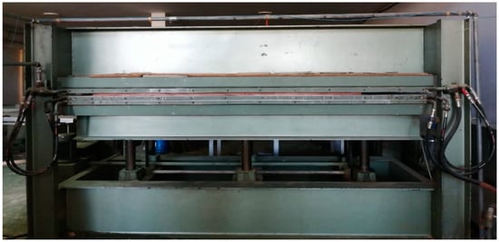
Figure 1.
Press machine inside the factory.
2.2. Suggested Heat Recovery System
The primary source of energy in the press machine is the boiler, which is used to heat water. The boiler uses diesel as the only fuel source. However, the output hot gases from the combustion process, during operation, pass through the exhaust gas pipes to the landscape. Yet these exhaust gases are lost energy, which it has been suggested can be recovered by a water tank placed around the exhaust gas pipe. Moreover, a heating chimney is placed in the industry for heating the internal space in the winter season that uses wood scraps and wastes for burning. Yet, this chimney shows an excess heat that result from wood burning after reaching the satisfying warm temperature in the space. Therefore, it is suggested to install a heat exchanger inside the chimney to benefit from the excess of heat in heating water. The water pipes will be connected between the chimney and the press machine water pipes system. Table 3 displays the energy sources in the system and where they are located.

Table 3.
Energy sources in the system.
2.3. Experimental Setup and Instrumentation
The system mainly includes a hydraulic thermal peel press machine and the corresponding sources of energy used to heat water and ensure the machine functions. The sources of heat in this experiment are:
The boiler, which is the primary initial source of heat in the system.
The heat recovered from the boiler’s exhaust gases, using a water tank around the exhaust pipe.
The excess of heat in the chimney, using a boiler tank inside the chimney.
The recovered heat from exhaust gases of the chimney, using a water tank around the exhaust pipe.
However, water passes through metal pipes from the heat sources to the metal plates of the press machine. Heating these metal plates will dissolve the thermal glue between wood and natural peel. The wood plate with natural peeling on its surface is then ready to be delivered to the customer. On the other hand, water valves are connected to the metal pipes so that different tests can be applied in specific conditions. Yet, K-type thermocouples are located inside water and exhaust gas pipes to take readings using Data-Logger. The designed system allows us to study every experiment separately, and combine two or more experiments in any study. Figure 2 shows a schematic drawing for the sum-up setup for all the connections on the press machine, in addition to the location of the used thermocouple. Moreover, all experiments can be combined and work at the same time by using the appropriate hydraulic valves. However, Table 4 shows the numbering and position of each thermocouple. The experimental setup is applied to the system, and the experiments are performed. Results are then obtained and analyzed, making it possible to draw conclusions about the best system from the test configuration to be applied to the press machine, on the grounds of criteria for choosing the best one, which emphasize efficiency and savings of energy, time, and money.
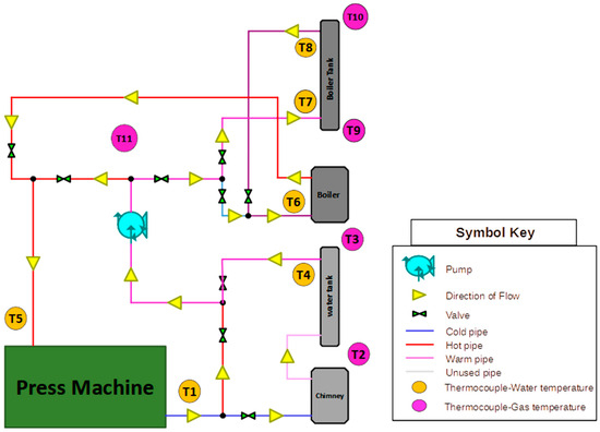
Figure 2.
Schematic of sum-up setup for all press machine connections.

Table 4.
Types of thermocouples and their distribution in the system.
2.4. Uncertainty and Reliability Tests
Measurements are conducted to evaluate the thermal characteristics of water pipelines in various test setups. The temperature T in °C is the most influential and significant parameter in the research. K-type thermocouples are used to monitor temperatures at various locations inside the prototypes with an accuracy of ±1.5 °C and a resolution of 0.25, as stated by the manufacturer [18]. Temperature data is captured at 10 s intervals by using the PA Hilton data to collect device and associated HDL software. Data is exported and converted into Excel tables by using a desktop computer linked to the data logger. Table 5 shows the parameters used in this part. Repeatability tests were conducted and uncertainty analysis was carried out using two methodologies:

Table 5.
Parameters used and their corresponding symbol.
- Standard uncertainties for quantities acquired by devices with known accuracy are determined using the rectangular distribution (Equation (1)).
However, the combined uncertainty for thermocouples is determined using Equation (2), taking into account the precision error of temperature measurement associated with thermocouple fixation (calculated as standard uncertainty) and the repeatability standard deviation [59] (EURACHEM/CITAC Guide CG 4), which are written as follows:
is obtained from repeatability tests that are shown in Figure 3 which displays repeatability testing for thermocouples T1, T2, and T3. Yet, it is calculated using Equation (3) [60]. This test is done by heating cold water in a container 3 times under similar test conditions for a specified time interval.
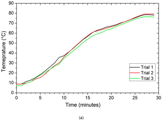
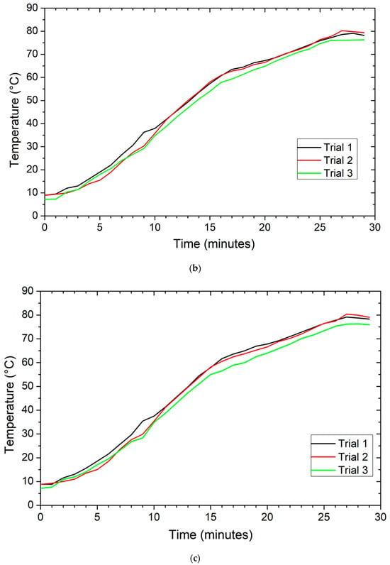
Figure 3.
Repeatability tests for temperatures T1 (a), T2 (b), and T3 (c) as a function of time, with N = 3.
Table 6 outlines the outcomes of uncertainty tests conducted on the thermocouples of the study and specifies the confidence level. Yet, Figure 4 shows dependable findings from the thermocouples, with a standard deviation that is typically around 2.3% (Safe zone). The repeatability test is conducted three times (N = 3).

Table 6.
Comprehensive data about measuring instruments.
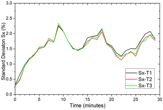
Figure 4.
Comparison of standard deviation curves for T1, T2, and T3 as a function of time.
On the other hand, the reliability test is performed, where the “boiler only” test is repeated two times with similar ambient conditions, starting water temperature, and ending water temperature. Graphs in Figure 5a–c show reliability tests for T1, T5, and T6, while graph in Figure 6 shows the temperature difference in reliability Tests T1, T5, and T6. This temperature difference values for thermocouples have an average of 1.73 °C during the experiment.
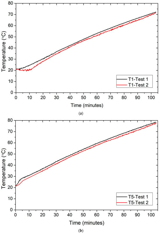
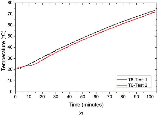
Figure 5.
Reliability tests for temperatures T1 (a), T5 (b), and T6 (c) as a function of time.
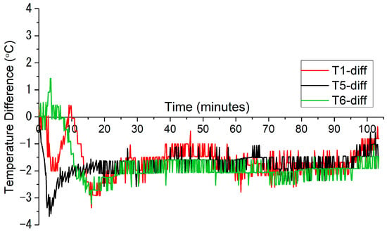
Figure 6.
Comparison of Reliability Tests for T1, T5, and T6 with respect to time.
2.5. Testing Configurations
A total of 22 tests were performed on different test configurations. The experiments were done during the cold winter season of 2022, between 23 January 2022, and 27 April 2022. All of the tests were used in the analysis. However, 5 suggested test configurations are applied (boiler Only, boiler + boiler tank, chimney, chimney + boiler Tank, all-in). Figure 7 shows the number of tests performed for each configuration, while Table 7 shows the primary and secondary sources of heat and thermocouples used for each test configuration.
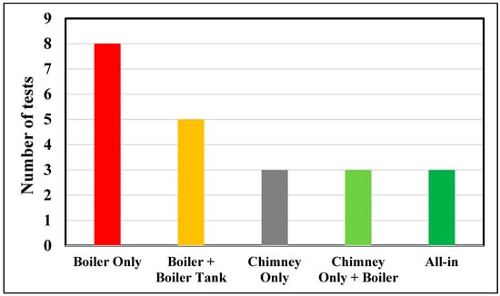
Figure 7.
Number of tests performed for each configuration.

Table 7.
Sources of heat and thermocouples used for each test configuration.
Boiler Only: Figure 8 shows the setup diagram of Experiment 1 explaining the connection of water pipes where cold water (blue pipe) enters the boiler to be heated up, before it passing through the circulating pump (red pipe) to enter the press machine plates, thus heating these plates, and then exiting the plates to enter back into the boiler for further heating.
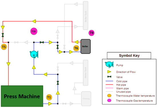
Figure 8.
Setup diagram of Experiment 1.
Boiler + Boiler Tank: Figure 9 shows the setup diagram of Experiment 2, explaining the connection of water pipes where cold water (blue pipe) enters the boiler water tank to be heated up from the recovery of exhaust gases. Then, it enters the boiler to be heated up (pink pipe) to the needed temperature. It then passes through the circulating pump (red pipe) to enter the press machine plates, thus heating these plates, before exiting the plates to enter back the boiler water tank, and then boiler, for further heating (blue pipe).
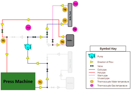
Figure 9.
Setup diagram of Experiment 2.
Chimney Only: Figure 10 shows the setup diagram of Experiment 3 explaining the connection of water pipes where cold water (blue pipe) enters the chimney water tank to be heated up by the excess of heat and the recovery of exhaust gases to reach the required temperature. It then passes through the circulating pump (red pipe) to enter the press machine plates, thus heating these plates, and exiting the plates to enter the chimney water tank for further heating (blue pipe).
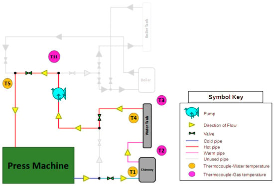
Figure 10.
Setup diagram of Experiment 3.
Chimney + Boiler: Figure 11 shows the setup diagram of Experiment 4 explaining the connection of water pipes where cold water (blue pipe) enters the chimney water tank to be heated up by the excess of heat and the recovery of exhaust gases. After this, it passes through the circulating pump (pink pipe) to enter the boiler for further heating, thus entering the press machine (red pipe) to heat the plates. It then exits the machine to enter again the chimney water tank for further heating (blue pipe).
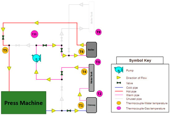
Figure 11.
Setup diagram of Experiment 4.
All-in: Figure 12 shows the setup diagram of Experiment 5 explaining the connection of water pipes where cold water (blue pipe) enters the chimney water tank to be heated up by an excess of heat and the recovery of exhaust gases. It then passes through the circulating pump (pink pipe) to enter the boiler water tank for further heating. After this, water enters the boiler (pink pipe) to reach the needed temperature, and enters the press machine (red pipe) to heat the plates, before exiting the machine to again enter the chimney water tank for further heating (blue pipe).
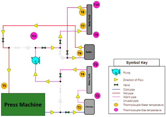
Figure 12.
Setup diagram of Experiment 5.
3. Results and Analysis
The performed experiments for all test configurations are emphasized on a main parameter of the study, namely temperature. A total of 11 thermocouples were used in the experiments, of which four were used for exhaust gas temperature measurements, six for water temperatures inside the pipes with different placements and positions, and one for air ambient temperature inside the factory. It is necessary to note that the operational temperature (T5 = 79 °C) is set by the manufacturer. The press machine is ready to start functioning at this temperature. The boiler is adjusted to this temperature, and turns off automatically when reaching this value, before turning on again when the temperature decreases to increase it again.
3.1. Thermal Behavior
In this part, two samples of the tests will be discussed, and corresponding graphs will be included. Figure 13 and Figure 14 show the variation of gas and water temperatures for thermocouples used in “boiler only” test configuration as a function of time, respectively. The duration of the test was 123 min. This value characterizes the time that the machine plates needed to reach their operational temperature (T5 = 79 °C). The ambient temperature was almost stable during the experiment (T11 = 11 °C). The gas temperature inside the exhaust pipe of boiler T9 increased from 11 to 260 °C within 4 min, and then was almost 260–270 °C during the operation of the boiler. T10 is not calculated in this test, because the boiler tank is not yet inserted. The temperature variation between the exhaust intake and output is insignificant. Nevertheless, the three thermocouples T5, T1 and T6 (water inlet of the press machine, water outlet of the press machine and water inlet of the boiler, respectively) showed similar temperature values at the beginning of the test (16.8 °C), while all the temperatures increased (after 123 min) to reach 79.9, 72.3 and 70.5 °C, respectively. This data indicates a temperature difference of around 7.5 °C between the entrance and output water in the press machine. This value represents the loss of heat that is mostly gained by the machine plates. This loss of heat only occurs in the first time operation, where the machine plates stick to each other before reaching the operating temperature. However, during the day work, this heat loss may increase due to the functioning of the machine, which will increase the surface area exposed to the space, therefore increasing convection. Yet the loss in pipes between the outlet of the press machine and the inlet of the boiler is 1.8 °C, which may be reduced to negligible values by insulating the pipes.
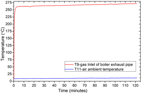
Figure 13.
Variation of gas temperatures for thermocouples used in the “boiler only” test as a function of time.
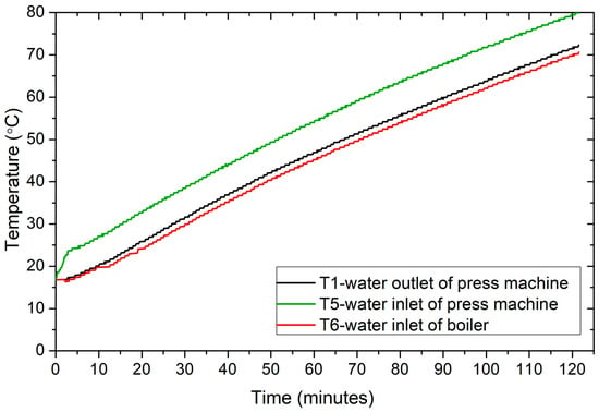
Figure 14.
Variation of water temperatures for thermocouples used in the “boiler only” test as a function of time.
In summary, this part discusses two tests on gas and water temperatures in a “boiler only” configuration, showing rapid temperature changes and thermocouple readings. It also discusses heat losses during initial operation and 1.8 °C heat losses in pipes between the press machine and boiler, suggesting insulation could reduce these losses. The analysis offers insights into thermal system dynamics and suggests strategies for improving efficiency.
Alternately, Figure 15 and Figure 16 show the variation of gas and water temperatures for thermocouples used in the “all-in” test configuration, respectively. Although the duration of the test was 90 min, 69 min were enough for the machine plates to reach their operational temperature (T5 = 79.2 °C). The extra 21 min after reaching the operational temperature in the test were used to observe the behavior of the test after this temperature was reached. The ambient temperature increased from T11-initial = 13 °C to reach 19 °C at the end of the test, an increase that was due to the usage of chimney in the factory in this test configuration. However, there was a temperature differential in the gas at the input and exit of the exhaust pipe of the boiler when the water tank was installed. The inlet of the exhaust pipe in the boiler T9 increased from 13 to 240 °C within 4 min, and then was almost 240–250 °C during the operation of the boiler. Consequently, the gas temperature at the outlet of exhaust pipe in the boiler T10 increased from 13 to 155 °C within 4 min, and then was almost 155–165 °C during the operation of the boiler. The difference in gas temperature between T9 and T10 is about 85–90 °C during the operation of the boiler, when heated water passed through the boiler water tank. Nevertheless, the six thermocouples (T1, T4, T5, T6, T7 and T8) showed similar temperature values at the beginning of the test (13.54 °C). The readings of these thermocouples at t = 69 min and t = 90 min are specified in Table 8. At t = 69 min, T5 showed a maximum temperature 79.2 °C. The difference in temperature between water entering and exiting the press machine is 8.5 °C. This value represents the loss of heat, which is mostly gained by the machine plates. It is noted that the difference between temperatures T4 and T7 is 0.5 °C, and between T8 and T6 is 0.4 °C. These values represent the loss of heat at that instant, in the pipes passing from one source of energy to another one.
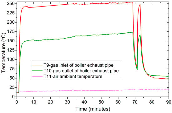
Figure 15.
Variation of gas temperatures for thermocouples used in the “all-in” test as a function of time.
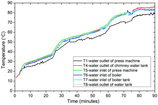
Figure 16.
Variation of water temperatures for thermocouples used in the “all-in” test as a function of time.

Table 8.
Readings of thermocouples in the “all-in” test, at t = 69 min and t = 90 min.
This part described tests conducted under an “all-in” configuration, focusing on gas and water temperature variations. The machine plates reached operational temperature (79.2 °C) after 69 min, with ambient temperature rising from 13 °C to 19 °C due to chimney usage. Gas temperatures at the boiler exhaust inlet and outlet increased rapidly, stabilizing during boiler operation. Thermocouples initially recorded similar temperatures but later diverged.
After reaching the operational temperature, the temperature behavior of thermocouples T9 and T10 in Figure 15 is analyzed, showing that the boiler worked once after a few minutes for about 2 min, and was then turned off. In the boiler working mode, it has a set temperature, and turns off automatically when it is reached, and turns on again when it decreases. This happens across the working day, whenever the operating temperature T5 decreases below its operating value. However, T9 and T10 (gas temperatures in the boiler exhaust pipe), will immediately increase when the boiler turns on, and vice versa. Conversely, the chimney is operating during all of the test, even when the boiler is turned off (i.e., when it is at operational temperature). This is because the chimney is initially operating for heating, and will therefore stay operational all the time. At t = 90 min, the thermocouple with the highest temperature value is (T4 = 87.9 °C), which is placed at the outlet the of chimney water tank (the only source of heat at this instance), and the temperature value at the inlet of the press machine is (T5 = 83 °C). The temperature difference between the output of the chimney water tank and the entrance of the press machine is therefore 4.9 °C. This value represents the loss of heat in the pipes. It is noted that T5 is higher (by 3.8 °C) than the operational temperature, which is caused by the heating of the chimney.
The analysis reveals a dynamic operation of the boiler and chimney system, with the boiler cycling intermittently based on temperature thresholds, causing heat losses in pipes and raising temperatures that are above operational levels, emphasizing the need for efficiency optimization and pipe insulation improvements.
3.2. Energy Analysis
In order to study and analyze the energy of all test configurations, it is necessary to clarify that when the system reaches the operational temperature, employees start using the machine. However, human work cannot be considered continuous on a systematic basis. If no test then reaches the steady state, the analysis should be done in transient mode. Furthermore, some variables, such as starting ambient air temperature T11, starting water press inlet temperature T5, and duration of the test, are not the same in all of the 22 tests. However, water flow rate inside the system is found to be constant. Consequently, a new parameter “Rate of Temperature Difference” is defined, to analyze the test configurations and their heating behavior with respect to the different variables. It mainly depends on the temperature difference of water press inlet temperature T5 and the test duration.
Table 9 shows a comparison between two experiments applied on the “boiler only” test configuration to inspect the ambient temperature effect on the duration of the test, and, therefore, on the rate of temperature difference.

Table 9.
Comparison of two experiments applying the “boiler only” test.
The two experiments had similar starting operating temperature T5-A = 19.92 °C, and T5-B = 19.33 °C. The starting ambient temperature was T11-A = 8.86 °C and T11-B = 15.7 °C. Test A, with lower ambient temperature, needed 117.67 min to reach the operational temperature, while Test B, with higher ambient temperature, and needed 103 min to reach the operational temperature. Therefore the rate of temperature difference in Test B (0.586) was higher than that of Test A (0.506) which means that the same test configuration with similar initial conditions will give better results, in terms of time and energy saving.
Figure 17 illustrates the correlation between the rate of temperature difference and the initial ambient temperature in the “boiler only” test setup, which included eight distinct tests. Ambient temperature directly influences the rate of heating over time. Rising ambient temperature reduces the temperature difference between the ambient air and the water pipes, leading to a reduction in energy loss because of convection between the pipes and the air.
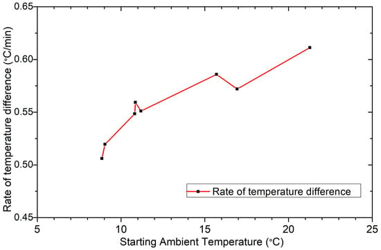
Figure 17.
Variation of rate of temperature difference with respect to starting ambient temperature.
After calculating the average starting ambient temperature and the rate of temperature difference for each test configuration, the variation of each parameter among all configurations is illustrated in a bar graph shown in Figure 18. The experiment obtaining the highest rate of temperature difference shows best efficiency, because the heat rate is increased; energy and fuel savings also increase. Additionally, the initial ambient temperature impacts the system’s productivity. A lower ambient temperature results in increased heat loss to the surroundings, leading to a reduction in the heat rate and efficiency of the system. This graph demonstrates that, depending on the two parameters studied, the “chimney only” test configuration shows the lower efficiency, while the “chimney + boiler only” counterpart proved to be the most efficient configuration in terms of energy. Results show that placing the boiler tank on the exhaust pipe of the boiler is not efficient, as shown by the observation of (taking into account a tiny difference in the average starting ambient temperature) a lower rate of temperature difference, compared to the “boiler only” test.
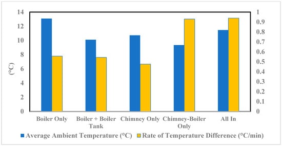
Figure 18.
Variation of average ambient temperature and rate of temperature difference among all configurations.
3.3. Economic Analysis
The main challenges for any heat recovery technology are social considerations, sustainability and economic factors. Thus, paybacks of any recovery system revolve around economic savings [21,52,61]. To perform the economic analysis of the current study, some parameters are specified. In addition, to investigate the alteration of fuel cost among test configurations, a new parameter is defined, namely “Fuel Cost Rate”. It depends on the fuel cost of the test and the temperature difference , which characterizes the heating amount needed for operating.
On the other hand, a test to calculate the consumption of the boiler is executed. However, based on the average daily earnings of the industry, specified by the accounting office of the industry, which takes 10 working hours in a day as an average value, the industry earns ($134) from the daily functioning of the thermal peeling press machine. The average earnings of one working hour is then obtained by dividing the average daily earning ($134) by the number of working hours while the machine is operating (8 h), when there is no production during the first two hours of heating before it reaches the operational temperature. The average earnings obtained in one working hour is then obtained by dividing the average daily earnings (134/8), and are found to be equal to 16.75 $/h. Table 10 shows the parameters used for energy analysis and the corresponding expected earnings in one hour of a normal working day in the factory. However, the total fuel cost per first operation ($) is the boiler’s fuel consumption (L) during the first-time operation multiplied by the price of fuel ($/L), which is then taken as an average for the experiments performed in each test configuration. Table 11 shows the fuel cost rate of each configuration with the exception of “chimney only”, as the boiler is not applied in this configuration and is turned off in this experiment, meaning there is no fuel consumption during the test. “Chimney + Boiler Only” and “All-in” configurations show a lower rate of fuel cost (0.055 $/°C), which means that the cost of heating water to 1 °C is 0.055 $. These results are more promising than those of “Boiler Only” and “Boiler + Boiler Tank” configurations, which display a rate of fuel cost (0.093 $/°C). Therefore, applying two main sources of energy (“boiler and chimney”) at the same time yields reduced fuel cost and produces money saving.

Table 10.
Parameters for energy analysis.

Table 11.
Fuel cost rate of each configuration.
In all of the 22 tests, the initial water flow rate in the applied system was fixed. Yet, water flow rate can be changed, which is something that must be studied. Hence, a manual valve and a water flowmeter are inserted after the circulating up. The initial flow rate was 35.8 L/min, and a “boiler only” experiment was confirmed. Nonetheless, after 2 days, the valve was partially closed to reach a water flow rate of 22.8 L/min before operating the system, and the same experiment was performed. Results in Table 12 show that both experiments had a similar starting ambient temperature T11 = 26 °C. Test 2, with a lower flow rate than that of Test 1, had a higher rate of temperature difference (0.63 > 0.59 °C/min) and a lower rate of cost (0.079 < 0.085 $/°C). In other words, the flow rate of Test 2 (22.8 L/min) is more competent in terms of energy and money.

Table 12.
Flow rate test comparison.
The difference of starting T5 between test 1 and 2, is related to the self-cooling of the press machine plates during night (heat loss to the surrounding), which is mostly affected by the ambient temperature during this period of day.
For a better comparison of all test configurations, the average of results of each configuration is used in Table 13 to calculate the cost of fuel for first operation at the beginning of the working day, which produces the best configuration, in economic terms. However, the “chimney only” test does not have any fuel consumption, as the boiler is turned off during the experiment, which produces fuel, and therefore, money saving. However, fuel consumption is not the only factor in economic analysis, as time is likewise a very effective factor. Consequently, the duration of a test must be analyzed to estimate the time lost during the excess operation duration, thus making it possible to calculate the missing expected earnings at this excess time and the excess fuel consumption. On the contrary, if the test’s operation duration is less than the usual duration, the saved hours yield more productive working hours, and therefore, economic profit. In this study, therefore to be 150 working days (across the winter and fall seasons) when the chimney operation is needed. Nevertheless, the “boiler only” test configuration is the system initially applied on the press machine in the factory. Therefore, this configuration is considered to be a “control test” for comparing fuel consumption, fuel cost and money savings. The average starting T11 is between 9.36 and 11.47 °C, which is an acceptable range to compare tests with each other.

Table 13.
Average of results of each test configuration.
In order to calculate overall money savings or losses, some terms must be clarified:
- Duration of a test represents the time needed for the system to reach the operational temperature T5. Therefore, all calculations of fuel and money savings are meant to only apply to this duration, and do not include all the working hours of a day;
- Heating time of a test is stated with an excess/less time, when compared to the average duration of “boiler only” tests;
- An excess of heating time in a test means that there is less production due to waste of time in heating; thus, the productive functioning hours of the machine are decreased. Therefore, the expected earnings of the day are decreased, where the average of earnings is 16.75 $ for one working hour of a day (Table 13);
- A decrease of heating time in a test means that there is more production due to saving time in heating; thus, the productive functioning hours of the machine are increased. Therefore, the expected earnings of the day are increased, where the average of earnings is 16.75 $ for one working hour of a day (Table 13);
- The terminology used is illustrated in Table 14;
 Table 14. Terminology used and their corresponding symbols.
However, some equations are illuminated:
- Time lost or gained in Heating (h):
- Expected Earnings from heating time ($):
Results of test configurations are each demonstrated in a definite table.
- For the “boiler only” test, the control test shown in Table 15, the total fuel cost for 150 working days was $865.01.
 Table 15. Fuel Cost for Experiment 1.
 - For the “boiler + boiler tank” test, shown in Table 16, there was a $129.72 loss in 150 days, compared to when the “boiler only” configuration was applied.
 Table 16. Total savings for Experiment 2.
Where total savings (TS) for 150 days are calculated:
- 3.
- For “chimney only”, as shown in Table 17, this test had a $346.85 loss during 150 days, compared to when the “boiler only” configuration was applied.
 Table 17. Total savings for Experiment 3.
Where total savings (TS) for 150 days are calculated:
- 4.
- For “chimney + boiler”, as shown in Table 18, this test produced $699.27 for 150 days, compared to when applying the “boiler only” configuration was applied.
 Table 18. Total savings for Experiment 4.
Where total savings (TS) for 150 days are calculated:
- 5.
- For “all-in”, as shown in Table 19, this test produced $700.47 earnings during 150 days, compared to when applying the “boiler only” configuration was applied.
 Table 19. Total savings for Experiment 5.
Where total savings (TS) for 150 days are calculated:
After energy analysis and economic study, an overall assessment should be made of the test configurations used. Comparing “boiler only” with “boiler + boiler tank”, results showed that, under similar conditions, both configurations produced similar results for rate of temperature difference and rate of fuel cost. The money loss in 150 days was $129.72 for the “boiler + boiler tank” test, which therefore proved that this heat exchanger is not efficient in this system. Comparing “boiler only” with “chimney only”, results showed that, under similar conditions, “chimney only” had a lower rate of temperature difference. In other words, it needs more time to heat the system. Alternatively, this configuration does not consume fuel. However, it had a $346.85 loss for 150 days compared to when the “boiler only” configuration was applied, which was due to the long time needed for heating. As a result, “boiler only” is found to be better economically. Finally, when “boiler only” was compared to “chimney + boiler only” in similar conditions, “chimney + boiler only” showed a higher rate of temperature difference and lower rate of fuel cost. In addition, it verified a $2307.39 savings in 150 days. Therefore, “chimney + boiler only” is more economically efficient.
4. Conclusions
The analysis of the press machine’s thermal efficiency, which is crucial for gluing wood peelings to thermal glue, provided valuable insights that were obtained through experimental research. Five different setups were examined: “boiler only”, “boiler + boiler tank”, “chimney only”, “chimney + boiler only”, and “all-in”. Moreover, the effects of water flow rate and ambient air temperature changes were also investigated. The careful combination of precise testing and analysis helped to uncover important facts that will support sustainability, accuracy, and efficiency in the system under study. The key conclusions are:
System sustainability: under the extended testing phase, the system, supported by crucial instrumentation, showed exceptional resilience, highlighting its durability and stability under severe experimentation while maintaining result integrity.
Data accuracy verification: The precision of findings is illustrated by using Data-Logger technology and K-type thermocouples to validate data accuracy, guaranteeing the reliability and strength of the results.
Credibility: The study’s credibility was strengthened by demanding uncertainty, repeatability, and reliability testing, confirming the methodological precision and scientific validity of this investigation.
Impact of ambient conditions: The study revealed that ambient variables, namely the initial ambient temperature (T11) and operating temperature (T5), play a crucial role in affecting the effectiveness of different test setups.
Optimization through flow rate analysis: Analysis of water flow rates showed that lower flow rates, specifically 22.8 L/min, were effective in optimizing system performance, which highlights the significance of flow rate optimization in improving operational efficiency.
Chimney integration advantages: The addition of a chimney water tank resulted in positive effects, enhancing the operation of the planned system and meeting its main goal of heating the manufacturing area.
Optimal configuration identification: The study identified “chimney + boiler only” as the ideal configuration, on the basis that it offers more economic benefits, especially in autumn and winter.
Seasonal configuration suitability: Situational factors highlighted the suitability of the “boiler only” setup in spring and summer, eliminating the need for chimney use and underscoring the need to select the appropriate configuration, in accordance with the season.
5. Recommendations
Hybrid energy systems, which include both hybrid renewable energy systems (HRESs) and hybrid heat recovery systems (HHRSs), are important solutions to the challenges of industrial sustainability and environmental responsibility. As the industrial sector shifts towards eco-friendly options to meet pollution requirements, it is crucial to optimize the efficiency of these systems. In drawing on the findings of this research and referring back to the main objectives stated in the introduction, the following suggestions are put forward:
For current setup:
Standardize ambient and operational temperatures: Ensure that the beginning ambient temperature (T11) and operating temperature (T5) are constant for all test setups. This uniformity will enable more precise comparisons and thorough analysis of outcomes, fulfilling the need for accurate information.
Expand flow rate testing: Perform many experiments at different flow rates to enhance the study and draw stronger findings. Variations of flow rates may have an important effect on system performance and efficiency; it could be a way to optimize energy use and recover lost energy.
Optimize boiler tank heat exchanger: Research methods to improve the efficiency of the “boiler tank” heat exchanger, which will optimize the use of energy obtained from boiler exhaust gases. This optimization may result in significant energy conservation and operational improvements, which are both in line with the goal of decreasing carbon emissions and enhancing energy efficiency.
Enhance insulation: Install insulation on water pipes to reduce heat loss through solid–gas convection. Enhanced insulation will preserve thermal efficiency and decrease energy loss when in use, which aligns with the emphasis on waste heat recovery mentioned in the introduction.
For future studies:
Integrate renewable energy systems: Investigate incorporating renewable energy sources, including solar electricity, to enhance the current system throughout spring and summer. This increase is in line with the worldwide trend towards sustainable energy practices and may reduce dependence on conventional energy sources.
Optimize heat exchangers: Research methods to improve the effectiveness of heat exchangers in the system. Optimization should prioritize increasing heat transfer rates and reducing energy losses, with the aims of enhancing system performance and boosting the energy efficiency of industrial operations.
Evaluate working fluid variations: Assess the impact of varying the working fluid used within the press machine for system efficiency and operational parameters. Exploring alternative working fluids can offer insights into potential optimizations and enhance system resilience, which are both aligned with the discussion of renewable energy and energy management.
Integrate hybrid systems: Integrate HHRS with HRES techniques to generate synergistic gains in energy efficiency, cost savings, and environmental impact. Integrating technologies as waste heat recovery and renewable energy production may provide comprehensive solutions that can be efficiently applied to outbreaks of complex difficulties.
Incorporating the suggestions into future research projects will enhance the comprehension of hybrid energy systems and promote sustainable industrial practices that are aligned with global environmental goals.
Author Contributions
Conceptualization, M.K. and J.F.; Data curation, O.F.; Formal analysis, O.F., M.K., J.F., F.H. and C.C.; Investigation, O.F., M.K., J.F., F.H. and C.C.; Methodology, O.F., M.K. and J.F.; Project administration, M.K., J.F. and C.C.; Supervision, M.K., J.F. and C.C.; Validation, O.F.; Writing—original draft, O.F.; Writing—review & editing, M.K., J.F., F.H. and C.C. All authors have read and agreed to the published version of the manuscript.
Funding
This research received no external funding.
Data Availability Statement
Data are contained within the article.
Conflicts of Interest
The authors declare no conflict of interest.
References
- Jaber, H.; Ramadan, M.; Lemenand, T.; Khaled, M. Domestic thermoelectric cogeneration system optimization analysis, energy consumption and CO2 emissions reduction. Appl. Therm. Eng. 2018, 130, 279–295. [Google Scholar] [CrossRef]
- Jabri, M.; Masoumi, S.; Sajadirad, F.; West, R.P.; Pakdel, A. Thermoelectric energy conversion in buildings. Mater. Today Energy 2023, 32, 101257. [Google Scholar] [CrossRef]
- Rezk, H.; Mohammed, R.H.; Rashad, E.; Nassef, A.M. ANFIS-based accurate modeling of silica gel adsorption cooling cycle. Sustain. Energy Technol. Assess. 2022, 50, 101793. [Google Scholar] [CrossRef]
- Tavana, M.; Santos, F.J.; Mohammadi, S. A fuzzy multi-criteria spatial decision support system for solar farm location planning. Energy Strateg. Rev. 2017, 18, 93–105. [Google Scholar] [CrossRef]
- Jaber, H.; Khaled, M.; Lemenand, T.; Murr, R.; Faraj, J.; Ramadan, M. Domestic thermoelectric cogeneration drying system: Thermal modeling and case study. Energy 2019, 170, 1036–1050. [Google Scholar] [CrossRef]
- Shahsavari, S.; Boutorabi, S.M.A. A general approach to the mechanical analysis of continuous local inhomogeneity using continuum mechanics theory and a new general energy-based-model. Appl. Eng. Sci. 2023, 16, 100149. [Google Scholar] [CrossRef]
- Khaled, M.; Murr, R.; El Hage, H.; Ramadan, M.; Ramadan, H.; Becherif, M. An iterative algorithm for simulating heat recovery from exhaust gas—Application on generators. Math. Comput. Simul. 2018, 167, 92–103. [Google Scholar] [CrossRef]
- Jaber, H.; Khaled, M.; Lemenand, T.; Ramadan, M. Effect of generator load on hybrid heat recovery system. Case Stud. Therm. Eng. 2019, 13, 100359. [Google Scholar] [CrossRef]
- Sheikh, M.; Harami, H.R.; Rezakazemi, M.; Valderrama, C.; Cortina, J.L.; Aminabhavi, T.M. Efficient NH3-N recovery from municipal wastewaters via membrane hybrid systems: Nutrient-Energy-Water (NEW) nexus in circular economy. Chem. Eng. J. 2023, 465, 142876. [Google Scholar] [CrossRef]
- Zhang, H.; Wang, H.; Zhu, X.; Qiu, Y.J.; Li, K.; Chen, R.; Liao, Q. A review of waste heat recovery technologies towards molten slag in steel industry. Appl. Energy 2013, 112, 956–966. [Google Scholar] [CrossRef]
- Mehmood, S.; Zaman, K.; Khan, S.; Ali, Z.; Khan, H.u.R. The role of green industrial transformation in mitigating carbon emissions: Exploring the channels of technological innovation and environmental regulation. Energy Built Environ. 2023, 5, 464–479. [Google Scholar] [CrossRef]
- Al Naimat, A.; Liang, D. Substantial gains of renewable energy adoption and implementation in Maan, Jordan: A critical review. Results Eng. 2023, 19, 101367. [Google Scholar] [CrossRef]
- Hassan, Q.; Algburi, S.; Sameen, A.Z.; Salman, H.M.; Jaszczur, M. A review of hybrid renewable energy systems: Solar and wind-powered solutions: Challenges, opportunities, and policy implications. Results Eng. 2023, 20, 101621. [Google Scholar] [CrossRef]
- Li, C.; Li, Z.; Zhu, H.; Tian, Z.; Feng, W. Study on operation strategy and load forecasting for distributed energy system based on Chinese supply-side power grid reform. Energy Built Environ. 2022, 3, 113–127. [Google Scholar] [CrossRef]
- Martínez-Pérez, R.; Rios Fernández, J.C.; Laine Cuervo, G.; Soto Pérez, F.; Rubio-Serrano, F.J.; Gutiérrez-Trashorras, A.J. Comparative study of energy performance and water savings between hygroscopic and rankine cycle in a nuclear power plant. Case study of the HTR-10 reactor. Results Eng. 2023, 20, 101600. [Google Scholar] [CrossRef]
- Kubicki, J.; Kopczyński, K.; Młyńczak, J. Climatic consequences of the process of saturation of radiation absorption in gases. Appl. Eng. Sci. 2024, 17, 100170. [Google Scholar] [CrossRef]
- Al-nehari, H.A.; Mohammed, M.A.; Odhah, A.A.; Al-attab, K.A.; Mohammed, B.K.; Al-habari, A.M.; Al-fahd, N.H. Experimental and numerical analysis of tiltable box-type solar cooker with tracking mechanism. Renew. Energy 2021, 180, 954–965. [Google Scholar] [CrossRef]
- Faraj, K.; Khaled, M.; Faraj, J.; Hachem, F.; Castelain, C. Experimental Study on the Use of Enhanced Coconut Oil and Paraffin Wax Phase Change Material in Active Heating Using Advanced Modular Prototype. J. Energy Storage 2021, 41, 102815. [Google Scholar] [CrossRef]
- Jaber, H.; Khaled, M.; Lemenand, T.; Ramadan, M. Short review on heat recovery from exhaust gas. AIP Conf. Proc. 2016, 1758, 030045. [Google Scholar] [CrossRef]
- Omrany, H.; Soebarto, V.; Zuo, J.; Sharifi, E.; Chang, R. What leads to variations in the results of life-cycle energy assessment? An evidence-based framework for residential buildings. Energy Built Environ. 2021, 2, 392–405. [Google Scholar] [CrossRef]
- Farhat, O.; Khaled, M.; Faraj, J.; Hachem, F.; Taher, R.; Castelain, C. A short recent review on hybrid energy systems: Critical analysis and recommendations. Energy Rep. 2022, 8, 792–802. [Google Scholar] [CrossRef]
- Somu, N.; Kowli, A. Evaluation of building energy demand forecast models using multi-attribute decision making approach. Energy Built Environ. 2023, 5, 480–491. [Google Scholar] [CrossRef]
- Gomaa, M.R.; Mustafa, R.J.; Al-Dhaifallah, M.; Rezk, H. A low-grade heat Organic Rankine Cycle driven by hybrid solar collectors and a waste heat recovery system. Energy Rep. 2020, 6, 3425–3445. [Google Scholar] [CrossRef]
- Cui, X.; Islam, M.R.; Chua, K.J. Experimental study and energy saving potential analysis of a hybrid air treatment cooling system in tropical climates. Energy 2019, 172, 1016–1026. [Google Scholar] [CrossRef]
- Shirinbakhsh, M.; Harvey, L.D.D. Feasibility of achieving net-zero energy performance in high-rise buildings using solar energy. Energy Built Environ. 2023; in press. [Google Scholar] [CrossRef]
- Yu, S.; Liu, X.; Yang, J.; Han, F.; Wei, J. The optimization research on the coupled of active and passive energy supplying in public institutions in China. Energy Built Environ. 2022, 5, 288–299. [Google Scholar] [CrossRef]
- Alabi, T.M.; Agbajor, F.D.; Yang, Z.; Lu, L.; Ogungbile, A.J. Strategic potential of multi-energy system tpwards carbon neutrality A forward-looking overview. Energy Built Environ. 2023, 4, 689–708. [Google Scholar] [CrossRef]
- Faqihi, B.; Ghaith, F. A comprehensive review and evaluation of heat recovery methods from gas turbine exhaust systems. Int. J. Thermofluids 2023, 18, 100347. [Google Scholar] [CrossRef]
- Liu, J.; Ma, L.; Wang, Q. Energy management method of integrated energy system based on collaborative optimization of distributed flexible resources. Energy 2023, 264, 125981. [Google Scholar] [CrossRef]
- Lv, S.; He, W.; Hu, Z.; Jinwei, M.; Chen, H.; Feiyang, S.; Minghou, L. Experimental investigation of solar thermoelectric (STEG) cogeneration system. Energy Procedia 2019, 158, 892–897. [Google Scholar] [CrossRef]
- Lv, S.; He, W.; Wang, L.; Li, G.; Ji, J.; Chen, H.; Zhang, G. Design, fabrication and feasibility analysis of a thermo-electric wearable helmet. Appl. Therm. Eng. 2016, 109, 138–146. [Google Scholar] [CrossRef]
- Aguila-Leon, J.; Vargas-Salgado, C.; Chiñas-Palacios, C.; Díaz-Bello, D. Energy Management Model for a Standalone Hybrid Microgrid through a Particle Swarm Optimization and Artificial Neural Networks Approach. Energy Convers. Manag. 2022, 267, 115920. [Google Scholar] [CrossRef]
- Elnozahy, A.; Abd-Elbary, H.; Abo-Elyousr, F.K. Efficient energy harvesting from PV Panel with reinforced hydrophilic nano-materials for eco-buildings. Energy Built Environ. 2022, 5, 393–403. [Google Scholar] [CrossRef]
- Bozzini, B.; Emanuele, E.; Strada, J.; Sgura, I. Mathematical modelling and parameter classification enable understanding of dynamic shape-change issues adversely affecting high energy-density battery metal anodes. Appl. Eng. Sci. 2023, 13, 100125. [Google Scholar] [CrossRef]
- Khatri, R.; Goyal, R.; Sharma, R.K. Comparative experimental investigations on a low-cost solar cooker with energy storage materials for sustainable development. Results Eng. 2023, 20, 101546. [Google Scholar] [CrossRef]
- Salek, F.; Zamen, M.; Hosseini, S.V.; Babaie, M. Novel hybrid system of pulsed HHO generator/TEG waste heat recovery for CO reduction of a gasoline engine. Int. J. Hydrogen Energy 2020, 45, 23576–23586. [Google Scholar] [CrossRef]
- Li, Q.; Loy-Benitez, J.; Nam, K.J.; Hwangbo, S.; Rashidi, J.; Yoo, C.K. Sustainable and reliable design of reverse osmosis desalination with hybrid renewable energy systems through supply chain forecasting using recurrent neural networks. Energy 2019, 178, 277–292. [Google Scholar] [CrossRef]
- Hou, X.; Sun, R.; Huang, J.; Geng, W.; Wang, L. A hybrid combined heat and power system based on PEM fuel cell design for high-speed zero carbon service area. Int. J. Hydrogen Energy 2023, 48, 32527–32539. [Google Scholar] [CrossRef]
- Tan, Z.; Feng, X.; Yang, M.; Wang, Y. Energy and economic performance comparison of heat pump and power cycle in low grade waste heat recovery. Energy 2022, 260, 125149. [Google Scholar] [CrossRef]
- Wang, J.; Kang, L.; Liu, Y. A multi-objective approach to determine time series aggregation strategies for optimal design of multi-energy systems. Energy 2022, 258, 124783. [Google Scholar] [CrossRef]
- Jiang, Y.; Xu, J.; Leng, X.; Eghbalian, N. A novel hybrid maximum power point tracking method based on improving the effectiveness of different configuration partial shadow. Sustain. Energy Technol. Assess. 2022, 50, 101835. [Google Scholar] [CrossRef]
- Liu, C.; Jiang, Y.; Han, W.; Kang, Q. A high-temperature hybrid absorption-compression heat pump for waste heat recovery. Energy Convers. Manag. 2018, 172, 391–401. [Google Scholar] [CrossRef]
- Chaimongkol, N.P.; Deethayat, T.; Wang, D.; Kiatsiriroat, T. Waste heat harvesting from continuous blowdown for power generation via organic Rankine cycle network: Case study of a coal-fired power plant. Results Eng. 2023, 20, 101543. [Google Scholar] [CrossRef]
- Lümmen, N.; Nygård, E.; Koch, P.E.; Nerheim, L.M. Comparison of organic Rankine cycle concepts for recovering waste heat in a hybrid powertrain on a fast passenger ferry. Energy Convers. Manag. 2018, 163, 371–383. [Google Scholar] [CrossRef]
- Yang, Y.; Ren, C.; Tu, M.; Luo, B.; Fu, J. Theoretical Performance Analysis of a New Hybrid Air Conditioning System with Two-Stage Energy Recovery in Cold Winter; Elsevier Ltd.: Amsterdam, The Netherlands, 2020; Volume 117, ISBN 8613874886. [Google Scholar]
- Zhang, X.; Wu, J.; Li, Z.; Chen, Y. A hybrid flue gas heat recovery system based on vapor compression refrigeration and liquid desiccant dehumidification. Energy Convers. Manag. 2019, 195, 157–166. [Google Scholar] [CrossRef]
- Su, Z.; Yang, L. Peak shaving strategy for renewable hybrid system driven by solar and radiative cooling integrating carbon capture and sewage treatment. Renew. Energy 2022, 197, 1115–1132. [Google Scholar] [CrossRef]
- Zhou, Y. A multi-stage supervised learning optimisation approach on an aerogel glazing system with stochastic uncertainty. Energy 2022, 258, 124815. [Google Scholar] [CrossRef]
- Chen, L.; Xia, S.; Shi, S. Results in Engineering Minimum entropy generation paths for generalized radiative heat transfer processes with heat leakage. Results Eng. 2024, 21, 101759. [Google Scholar] [CrossRef]
- Wang, Y.; Wu, Y.; Tang, Y.; Li, Q.; He, H. Cooperative energy management and eco-driving of plug-in hybrid electric vehicle via multi-agent reinforcement learning. Appl. Energy 2023, 332, 120563. [Google Scholar] [CrossRef]
- Rastegarpour, S.; Mariotti, A.; Ferrarini, L.; Aminyavari, M. Energy efficiency improvement for industrial boilers through a flue-gas condensing heat recovery system with nonlinear MPC approach. Appl. Therm. Eng. 2023, 229, 120554. [Google Scholar] [CrossRef]
- Farhat, O.; Faraj, J.; Hachem, F.; Castelain, C.; Khaled, M. A recent review on waste heat recovery methodologies and applications: Comprehensive review, critical analysis and potential recommendations. Clean. Eng. Technol. 2022, 6, 100387. [Google Scholar] [CrossRef]
- Chen, J.; Wang, N.; Zhang, Z.; Zhang, L.; Fei, Q.; Ma, Y. Results in Engineering New insights into wine waste management: Zero waste discharge-driven full energy/resource recovery strategy. Results Eng. 2022, 15, 100606. [Google Scholar] [CrossRef]
- Tong, H.; Yao, Z.; Lim, J.W.; Mao, L.; Zhang, J.; Ge, T.S.; Peng, Y.H.; Wang, C.H.; Tong, Y.W. Harvest green energy through energy recovery from waste: A technology review and an assessment of Singapore. Renew. Sustain. Energy Rev. 2018, 98, 163–178. [Google Scholar] [CrossRef]
- Macháčková, A.; Kocich, R.; Bojko, M.; Kunčická, L.; Polko, K. Numerical and experimental investigation of flue gases heat recovery via condensing heat exchanger. Int. J. Heat Mass Transf. 2018, 124, 1321–1333. [Google Scholar] [CrossRef]
- Bonilla-Campos, I.; Nieto, N.; del Portillo-Valdes, L.; Egilegor, B.; Manzanedo, J.; Gaztañaga, H. Energy efficiency assessment: Process modelling and waste heat recovery analysis. Energy Convers. Manag. 2019, 196, 1180–1192. [Google Scholar] [CrossRef]
- Lu, D.; Chen, G.; Gong, M.; Bai, Y.; Xu, Q.; Zhao, Y.; Dong, X.; Shen, J. Thermodynamic and economic analysis of a gas-fired absorption heat pump for district heating with cascade recovery of flue gas waste heat. Energy Convers. Manag. 2019, 185, 87–100. [Google Scholar] [CrossRef]
- Sarpong, G.; Gude, V.G.; Magbanua, B.S.; Truax, D.D. Evaluation of energy recovery potential in wastewater treatment based on codigestion and combined heat and power schemes. Energy Convers. Manag. 2020, 222, 113147. [Google Scholar] [CrossRef]
- Rasul, S.; Kajal, A.M.; Khan, A. Quantifying Uncertainty in Analytical Measurements. J. Bangladesh Acad. Sci. 2018, 41, 145–163. [Google Scholar] [CrossRef]
- Sun, W.; Zhang, Y.; Ling, Z.; Fang, X.; Zhang, Z. Experimental investigation on the thermal performance of double-layer PCM radiant floor system containing two types of inorganic composite PCMs. Energy Build. 2020, 211, 109806. [Google Scholar] [CrossRef]
- Salisu, S.; Mustafa, M.W.; Olatomiwa, L.; Mohammed, O.O. Assessment of technical and economic feasibility for a hybrid PV-wind-diesel-battery energy system in a remote community of north central Nigeria. Alex. Eng. J. 2019, 58, 1103–1118. [Google Scholar] [CrossRef]
Disclaimer/Publisher’s Note: The statements, opinions and data contained in all publications are solely those of the individual author(s) and contributor(s) and not of MDPI and/or the editor(s). MDPI and/or the editor(s) disclaim responsibility for any injury to people or property resulting from any ideas, methods, instructions or products referred to in the content. |
© 2024 by the authors. Licensee MDPI, Basel, Switzerland. This article is an open access article distributed under the terms and conditions of the Creative Commons Attribution (CC BY) license (https://creativecommons.org/licenses/by/4.0/).