1. Introduction
As a novel variable cycle engine (VCE), an adaptive cycle engine (ACE) has the advantages of high specific thrust at supersonic cruise, low specific fuel consumption and high thrust-to-weight ratio at subsonic cruise [
1,
2,
3]. So, it has attracted wide attention [
4,
5]. Its high performance is due to the ability of ACE to switch between triple-bypass and double-bypass modes, thus enabling it to operate in a thermal cycle that is more compatible with the flight state. Switching between the two modes is one of the key technologies of the ACE, and it is crucial to design an optimal mode switching control law to ensure the ACE operates safely, smoothly and quickly during the mode transition process [
6,
7].
Most of the research on ACE is about steady state modeling, characterization and performance optimization [
8,
9], etc. The research on mode transition control has been reported less [
10]. The simple linear interpolation between the two modes is often used for geometric mechanism adjustment during the mode transition process, which is not able to ensure the performance of the engine during the transition state [
11]. GE researched the mode transition process of the YF120 engine, but the control law design method was kept strictly confidential [
12,
13,
14,
15]. Grönstedt [
16] of Sweden conducted an optimization study on the transition performance of a selective bleed VCE, and the guide vane angles of the three compression components, the adjustable areas of the three nozzles and the fuel flow were optimized by using the SQP algorithm to ensure a safe and smooth transition. Wang Hao [
17] et al. proposed a mode transition method with stepwise thrust change, and optimized the mode transition control law by using a differential evolutionary algorithm. However, no validation tests have been conducted for the robustness and adaptability of the control law. Yangjing Wang [
18] et al. determined the control variables corresponding to the starting and ending points of mode transition based on the sequential quadratic programming method, and the control variables are changed linearly to the ending point within 2.5 s. Chen Shangxi [
19] adopted a simple linear variation control law for open-loop control geometric during the mode transition of VCE and a normal and stable transition process is achieved. Zhu Baibin [
20] presented a mode transition control method combining of high-pressure speed controlled by fuel flow in closed-loop and other control variables adjusted in open-loop. However, the regulation schedule curves of the open-loop control variable s were given. Compared with the above method where the mode transition and geometric mechanisms adjustment are carried out simultaneously, Zheng Junchao [
21] et al. proposed that the mode transition point should be set to where the low pressure rotor speed and the thrust are the same under the two modes, and the geometric mechanisms (except the mode selection valve) are kept unchanged during mode transition through pre-adjusting the geometric mechanism linearly to the mode transition point, achieving a smooth mode transition process.
It can be seen that most of the mode conversion methods reported currently use linear change geometric mechanism control laws. Although this control method can achieve the normal and stable mode transition of VCE, the output parameters of the engine are prone to fluctuate greatly during the mode conversion process, which affects the safe operation of the engine. As a strongly nonlinear system, the nonlinear control law may be more suitable for VCE mode transition process. To achieve optimal mode transition control schedules of the geometric mechanism, in this paper, the particle swarm optimization (PSO) was adopted to optimize the trajectories of the open-loop geometric mechanism constructed by Bézier curves to ensure the cooperation of the open-loop and the closed-loop geometric mechanisms. To ensure the robustness of the control system in the switching process, the augmented linear quadratic regulator (ALQR) method was adopted to design the closed-loop controller. The trajectories of the open-loop geometric mechanisms were optimized in the outer loop to ensure a smooth and safe mode transition process.
The remainder of this paper is organized as follows.
Section 2 briefly introduces the principle of the mode transition process;
Section 3 presents the ALQR control method used in the closed-loop control;
Section 4 gives the structure of the proposed geometric mechanism optimization system; in
Section 5, simulation and analysis are reported to verify the feasibility and effectiveness of the proposed method;
Section 6 presents a summary.
2. Introduction of the Mode Transition Process
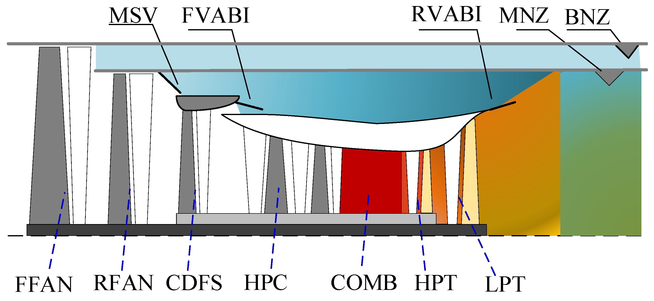
The structure of the ACE studied in this paper is shown in
Figure 1. The core-driven-fan stage (CDFS) and high-pressure compressor (HPC) are driven by the high-pressure turbine (HPT). The front fan (FFAN) and the rare fan (RFAN) are driven by the low-pressure turbine (LPT). The mode selection valve (MSV) controls the open and closed states of the second bypass [
22,
23,
24]. When the MSV is closed (MSV = 0), the ACE will operate at the double bypass mode. Otherwise, the ACE operates at the triple bypass mode (MSV = 1). The mode transition refers to the process whereby the MSV of ACE changes between 0 and 1.
There are 10 variable geometrics in the ACE researched, including the MSV, front and rare variable-area bypass injector (F/R VABI), variable stator vanes (VSV) of RFAN, CDFS and HPC, variable area guiders (VAG) of HPT and LPT, the third bypass nozzle area (BNZ) and the main nozzle (MNZ). The VSVs of RFAN and the VAG of HPT are scheduled according to the corrected speed of the LP and HP rotors to ensure the stable working of ACE. The schedules of the other variable geometrics are not determined during the mode transition process. Therefore, it is necessary to research their coordination working method to ensure the mode transition process is smooth and safe.
3. Closed-Loop Controller Design
The researched ACE adopts the double-variable closed-loop control method. The LP rotor speed
NL and the engine thrust
F are kept constant through the regulation of the main fuel
Wfm and the main nozzle area
A8. Considering that ALQR has the characteristics of a simple structure and strong robustness, and has a good research basis in aero engines [
25,
26,
27], the ALQR method was adopted to design the controller of the ACE.
The modeling principles and methods of aircraft engines have become relatively mature, as detailed in reference [
28]. The nonlinear mathematical model of ACE in the text is expressed as follows:
Linearize Equation (1) at the equilibrium point (where the low-pressure speed is 100%) and obtain the state variable model as follows:
where Δ
x = [Δ
NL, Δ
NH]
T, Δ
u = [Δ
Wfm, Δ
A8]
T, Δ
y = [Δ
NL, Δ
F]
T are the state, control and output vectors of the ACE, Δ indicates that the variables are small relative deviations from the equilibrium operating point (the magnitude of deviation in this paper is 1%) [
28],
NH is the HP rotor speed.
A,
B,
C,
D are system matrixes of appropriate dimensions.
Taking into account the dynamics of the actuators (i.e., geometric mechanism), the controlled object is the series connection of the actuator and the engine, and described as:
where
,
are the commands of the actuators.
where
Aa,
Ba are the system matrixes of the actuators.
To achieve the robust step signal tracking ability, the tracking errors are augmented into the state vector, so the model is changed into
where
,
e = [
NLr Fr]
T − [
NL F]
T is the tracking error vector,
NLr,
Fr are the commands of
NL,
F.
.
The ALQR controller for Equation (5) is
where
,
P is the solution of the following Riccati equation.
where
,
are the weighted matrixes of the following functional equation.
So, the property of the controller is determined by the weighted matrixes
Q and
R. To obtain the optimal controller, the PSO is adopted to optimize the parameters of
Q and
R. As a swarm-based algorithm, PSO searches the best solution thought the experiences of its own and the colony’s. The performance indicators of the optimization process are as follows:
where [
y1r y2r]
T = [
NLr Fr]
T, [
y1 y2]
T = [
NL F]
T.
To simplify the optimization process and ensure the positiveness of the weighted matrixes, Q∈6×6, R∈2×2 are set to diagonal matrixes. Therefore, the dimension of the optimization is 8 and the optimal controller matrix can be obtained after optimization. The fuel flow and the nozzle area can be determined by the closed-loop control.
4. Open-Loop Geometrics Scheduling Optimization
During the ACE mode transition process, in addition to the area of MNZ, VSVs of RFAN and VAG of HPT (the area of MNZ is the closed-loop control variable, and the VSVs of RFAN and VAG of HPT remain unchanged), the input trajectories of the other seven geometric mechanisms need to be determined. During the mode transition process, the MSV varies linearly between 0 and 1. In order to achieve the coordination between open-loop and closed-loop geometries, the inner loop adopts an ALQR steady-state controller, and the outer loop adopts PSO to optimizes the regulation schedules of the undetermined open-loop geometries according to the Bézier curve constructed [
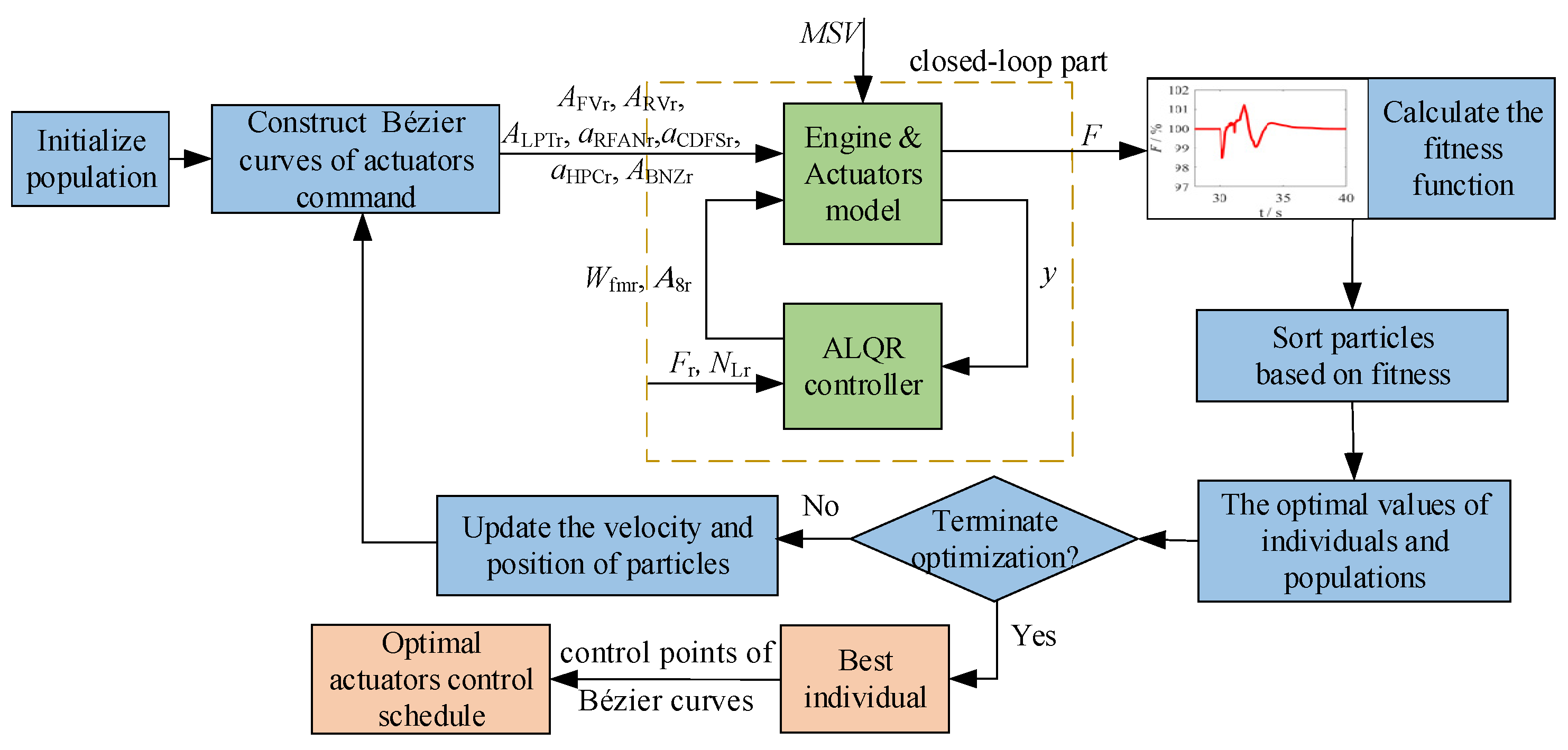
29]. The process of optimization is shown in
Figure 2, where A
FVr, A
RVr, A
LPTr and A
BNZr represent the command of FVBI area, RVBI area, LPT VAG area and BNZ area; α
RFANr, α
CDFSr and α
LPTr represent the angle commands of RFAN’s VSV, CDFS’s VSV and HPC’s VSV, respectively.
AFVr, ARVr, ALPTr, ABNZr are the area commands of the FABI, RVABI, LPT VAG, BNZ, respectively. αRFANr, αCDFSr, αHPCr are the angle commands of the VSV of FFAN, CDFS, HPC, respectively. They are scheduled based on the Bézier curves optimized by the PSO.
Bézier curves are mathematical curves applied to two-dimensional graphics applications. A Bézier curve equation
Bz(
t) containing np + 1 control points
Pi (
i = 0, 1, …,
np) can be expressed as a linear combination of Bernstein polynomials of order n.
where
is the scaling parameter. When it is changed from 0 to 1, the point on the Bessel curve moves from the starting point to the end point
.
Each geometric mechanism adopts five control points, and the mode transition time is set to 2 s; then, the time instants corresponding to the five control points are [0 s, 0.5 s, 1 s, 1.5 s, 2 s]. For seven open-loop control geometrics, seven Bézier curves are constructed, so there are 35 control points that need to be optimized. The position vector
X and the velocity vector
V of the
ith particle can be denoted as
Xi = [
Xi1,
Xi2, …,
Xi35],
Vi = [
Vi1,
Vi2, …,
Vi35]. The optimal position searched so far by the
ith particle is
pbest,i and the optimal position searched by the swarm is
gbest. So, the velocity and position of the particles are updated as follows:
where
g represents current iteration.
is an inertia factor,
c1,
c2 are non-negative acceleration factors,
r1,
r2 are random numbers between 0 and 1.
The target of the closed-loop control is to maintain
F constant during the mode transition process. Therefore, the particles are evaluated by the maximum offset of thrust to the command during the mode transition process.
where
Fmax, Fmin are the maximum and minimum thrust during the state transition process.
Each particle forms seven Bézier curves that generates the commands of the seven geometric mechanisms (i.e., actuators) during the mode transition process, and the particles are evaluated by Equation (12) that are determined by the cooperating of the open-loop geometric mechanisms and the closed-loop geometric mechanisms (determined by the ALQR). When the optimization satisfied the terminate condition, the best individual was output and formed optimal actuator control schedules of the open-loop geometric mechanisms.
Taking the switching from three-bypass mode to two-bypass mode at the subsonic cruise operating point (
H = 10 km,
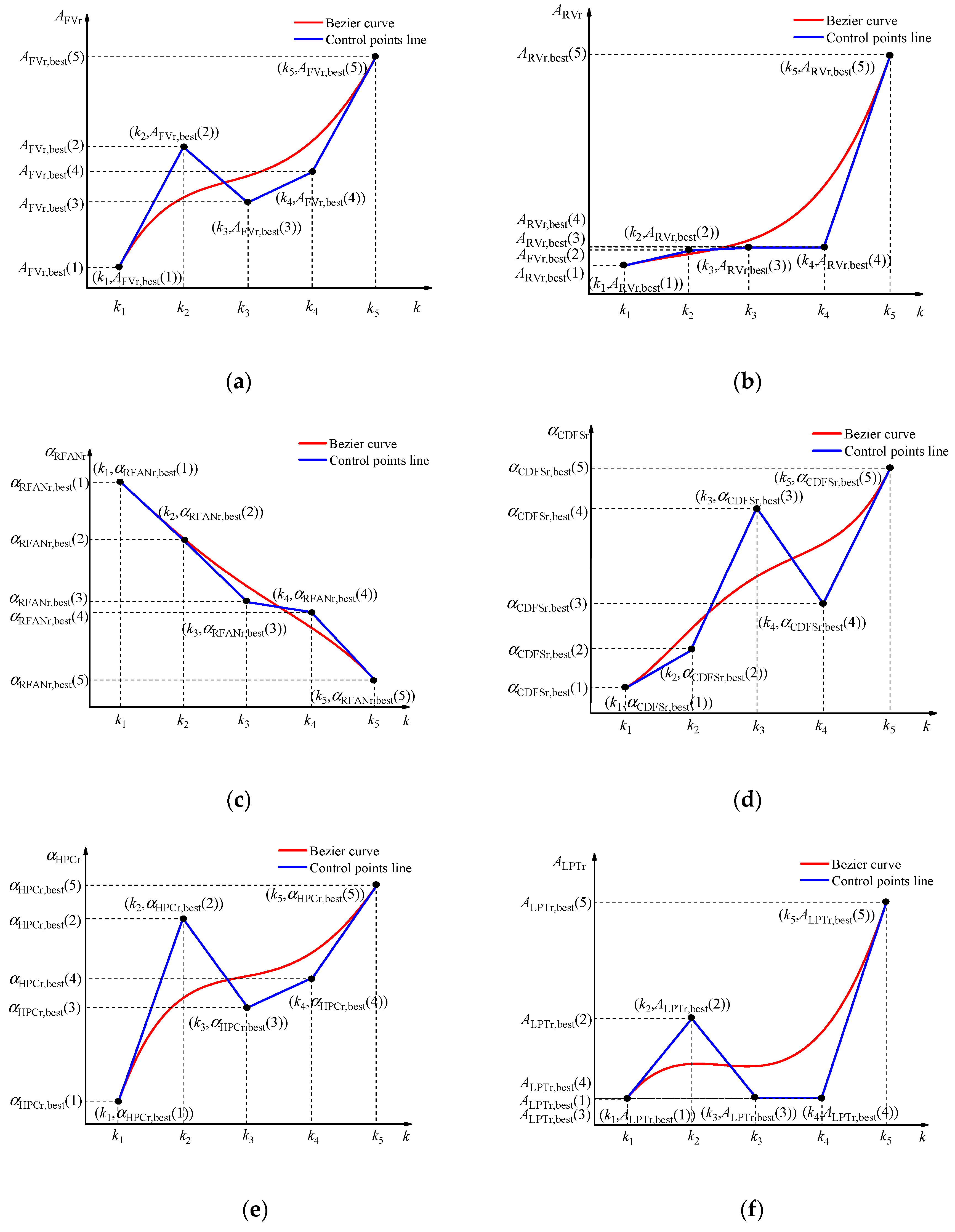
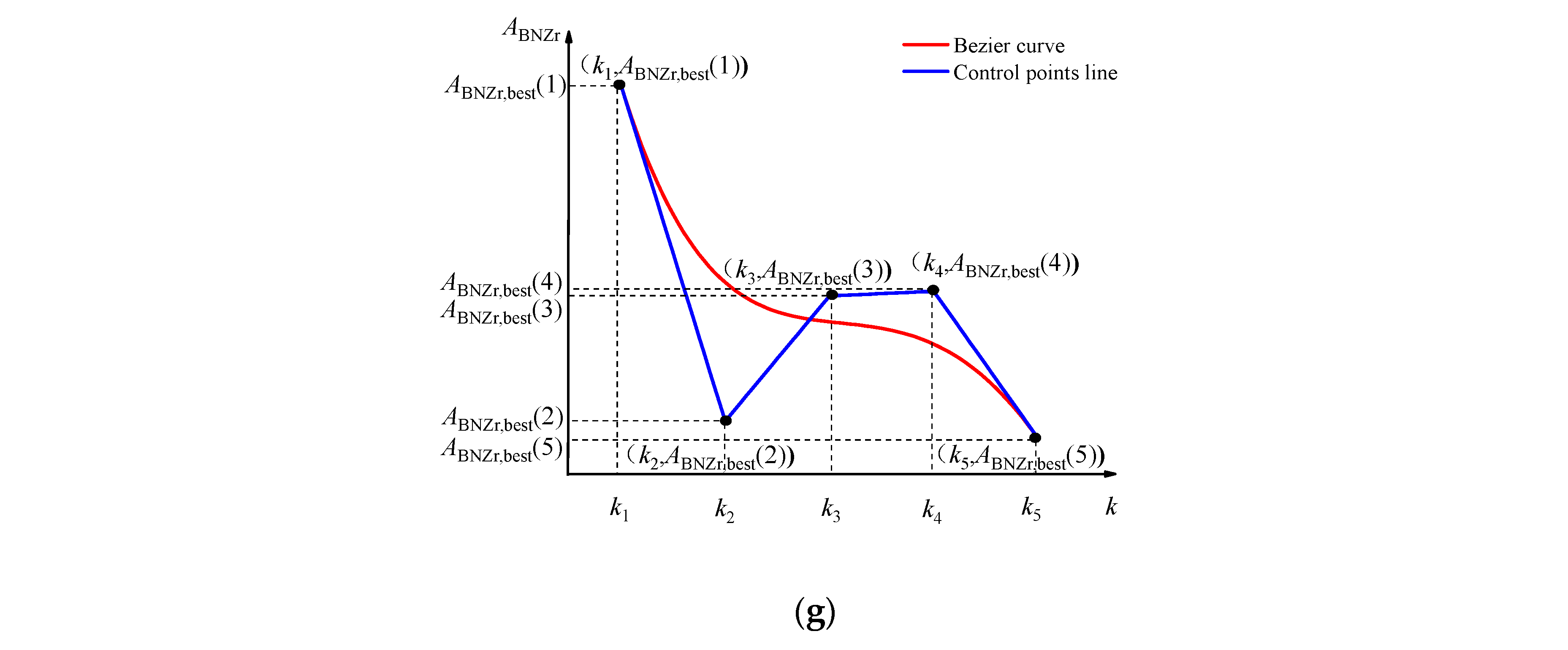
Ma = 0.9) as an example, the Bézier curve of each mechanism obtained is shown in
Figure 3, where “Bézier curve” represents the Bézier curve calculated by the optimal control points, and “Control points line” represents the variation of the optimal control points. The optimization of the Bézier curve is starting from the equilibrium point of the three-bypass operation mode, and ending point at the equilibrium point of the double-bypass operation mode.
From
Figure 3, it can be seen that the control schedules of the seven geometric mechanisms show an irregular smooth transition with the increase of the scaling factor
κ. When
κ changes linearly from 0 to 1, the time t changes linearly from 0 to 2 s, which allows the commands of the open-loop geometrical mechanisms to be varied over time during the mode transition process.
5. Validation
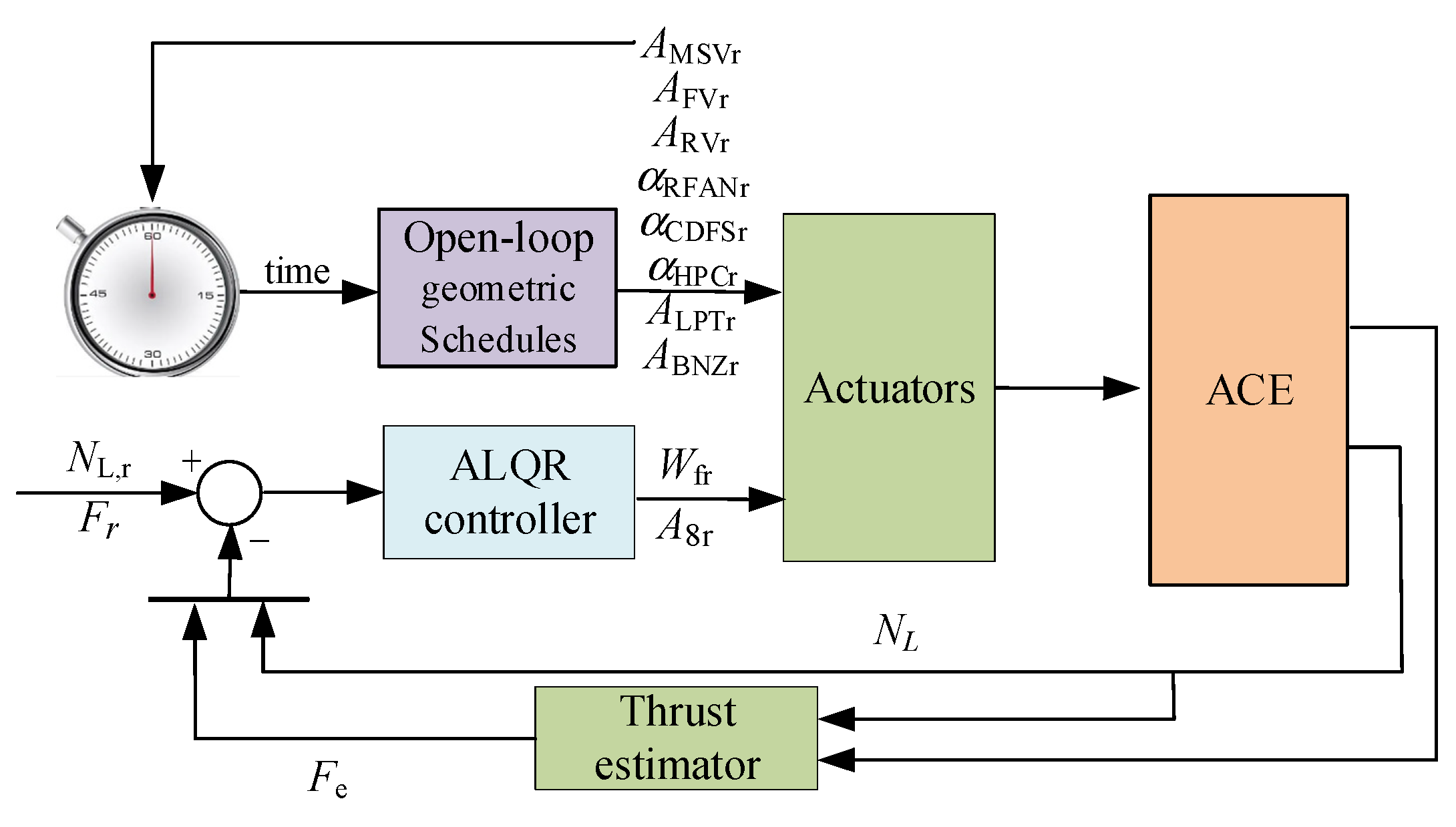
In order to verify the effectiveness, robustness and adaptability of the mode transition control, the transitions between double and triple-bypass mode are carried out in two typical flight conditions, subsonic cruise and supersonic cruise. In addition, the influence of Bézier curves orders on mode transition control are researched. Based on the open-loop geometric commands optimized under different conditions, a joint simulation verification of the open-loop and closed-loop regulation is carried out, and the structure of the control system verified in the simulation is shown in
Figure 4. At this point, the optimization results of ALQR controller parameters
and
are:
When a mode transition starts, the MSV area command changes with time and triggers the time counter for the mode transition; then, the seven geometry mechanism commands optimized by PSO are scheduled according to the time variation. The feedback thrust Fe is estimated by the thrust estimator of the neural network which is not introduced and the estimation error is not taken into account in this paper.
5.1. Validation of Mode Transition Control Effectiveness
- (1)
Result at the subsonic cruise point
In this simulation, the ACE is switched from triple-bypass mode to double-bypass mode at the subsonic cruise operating point (
H = 10 km,
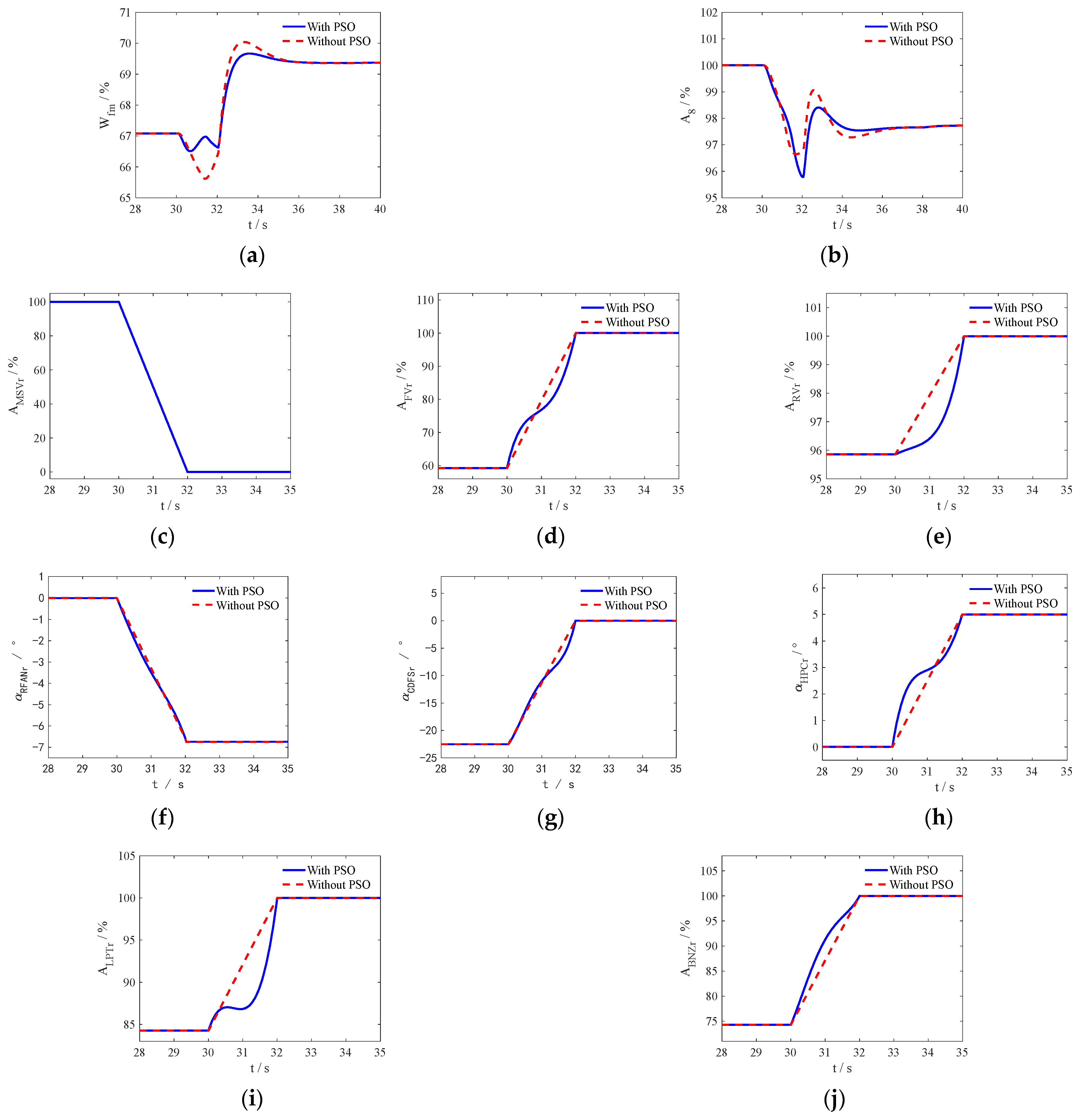
Ma = 0.9). The optimized actuator commands and engine responses are shown in
Figure 5 and
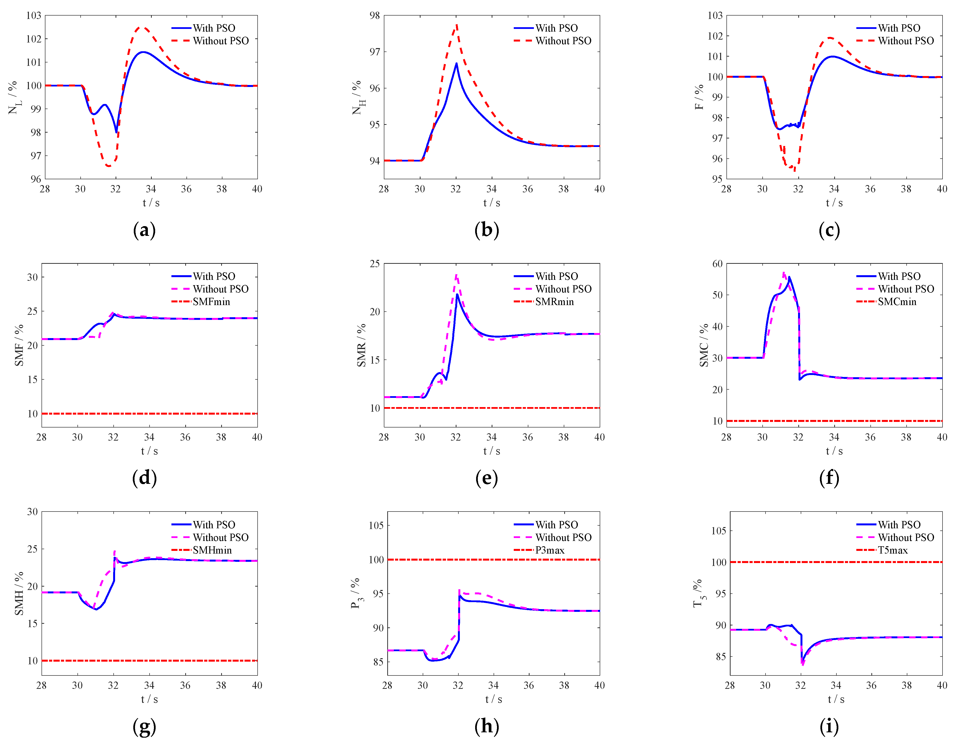
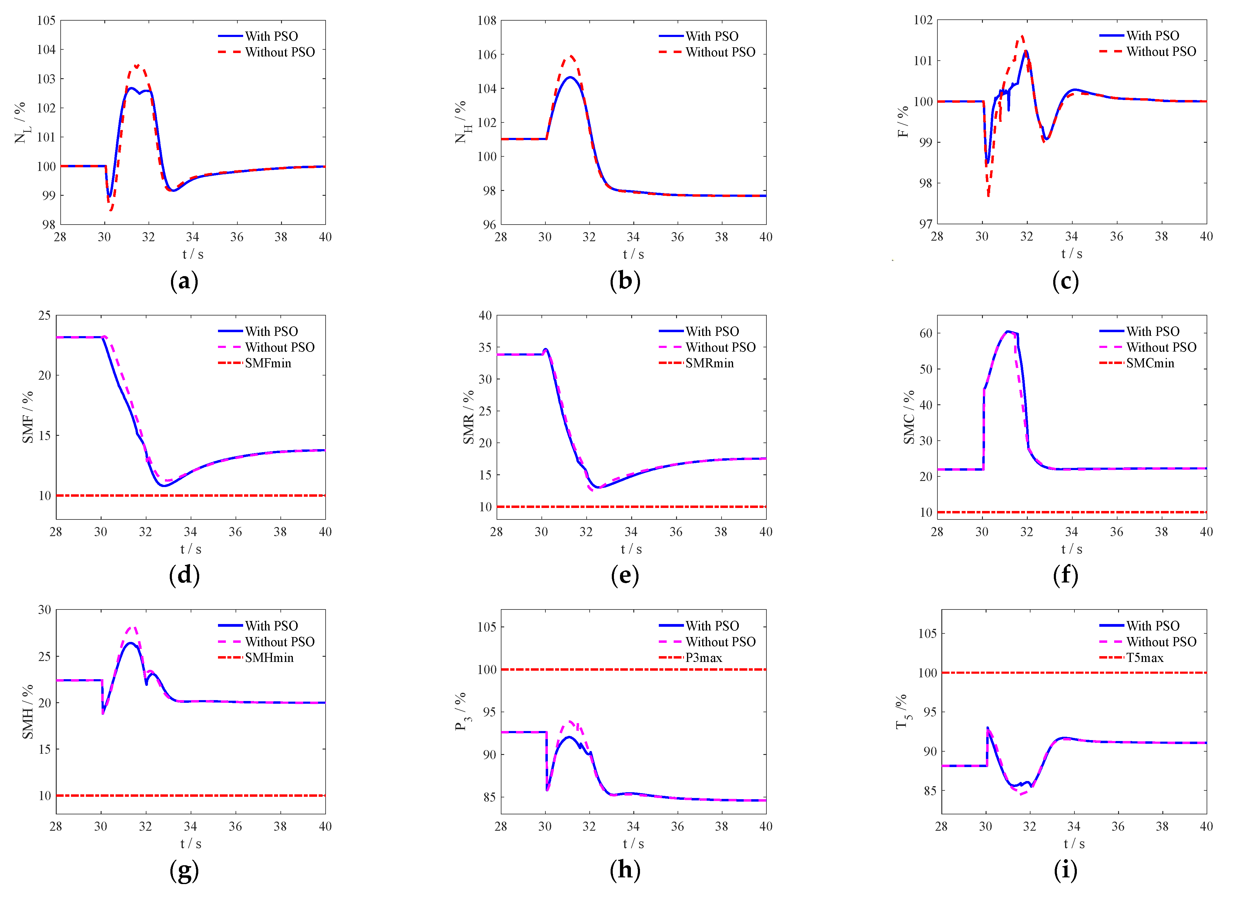
Figure 6, where “with PSO” denotes the optimization results obtained from the PSO, and “without PSO” is the result obtained from the conventional linear variation geometry mechanism. In
Figure 6,
SMF,
SMR,
SMC,
SMH are the surge margin of FFAN, RFAN, CDFS, HPC. respectively, and
P3 and
T5 are the output pressure and temperature of HPC and LPT, respectively. The subscript “min” and “max” represent the minimum and maximum limitation of the corresponding variables.
As
Figure 5 shows, the transition from triple-bypass to double-bypass mode starts at 30 s.
Figure 5a,b show the variation curves of the closed-loop control varaibles, where the fuel flow
Wfm increases and the area of MNZ
A8 decreases.
Figure 5c shows that the MSV area linearly changes from its maximum value to 0 within 2 s. From
Figure 5d–j, it can be seen that other geometric mechanisms of PSO exhibit nonlinear changes simultaneously. Except for the closed-loop control of the MNZ region
A8 being closed to a smaller size, the area and guide vane angle of other open-loop geometric mechanisms have increased to allow for more flow during the MSV closing process. The fuel flow
Wfmr is increased by 3.42% to maintain constant thrust in the dual-bypass mode, which also demonstrates that the triple-bypass mode has higher economy at subsonic cruise condition.
As
Figure 6 shows, it can be concluded from
Figure 6d–i that regardless of whether PSO optimization is present or not, the engine output is far from the constraint boundary. From
Figure 6a–c, during the transition process, the fluctuations in closed-loop thrust
F and LP rotor speed
NL are 2.58% and 2%, respectively. In the absence of linear changes in PSO, these numbers are 4.64% and 3.45%, respectively. In addition, the fluctuation of the HP rotor speed
NH under PSO is 2.28%, which is significantly smaller than the response of 3.35% without PSO. The results show that compared with traditional linear change methods, the mode transition control method can achieve a smooth, safe and fast transition from triple-bypass mode to double-bypass mode, and the control system with the optimized geometric mechanism control schedule achieves smaller thrust and rotor speed response fluctuations during the state transition process; the effectiveness of the control method proposed in this article has been verified.
- (2)
Result at the supersonic cruise point
In this simulation, the ACE is switched from double-bypass mode to triple-bypass mode at the subsonic cruise operating point (
H = 10 km,
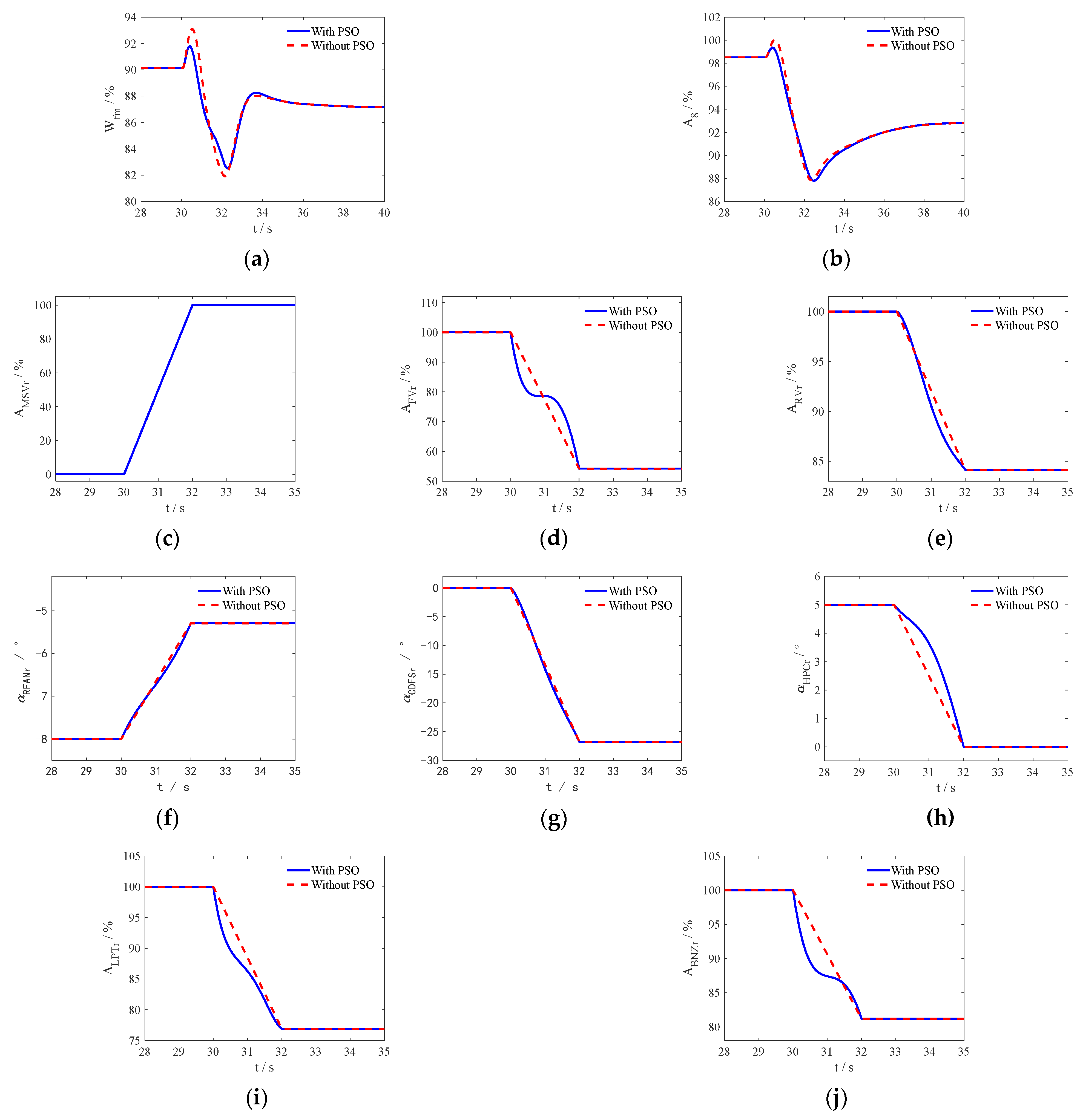
Ma = 1.2), and the optimized actuator commands and engine responses are compared with that of the traditional linear variation actuator commands as shown in
Figure 7 and
Figure 8.
As
Figure 7 shows, the transition from double-bypass to triple-bypass mode starts at 30 s. As shown in
Figure 7a,b, the closed-loop control variables
Wfmr and
A8r have both decreased.
Figure 7c shows that the MSV area linearly changes from 0 to 100% within 2 s.
Figure 7d–j show that during the mode transition process, the other geometric mechanisms optimized by PSO exhibit nonlinear changes, Except for α
RFANr is increased during the mode transition, the command for areas and guide vane angles of other geometric mechanisms are reduced to match the increased flow rate of the second bypass during the MSV opening process. The fuel flow
Wfm decreased by 3.32%, which also proves that the dual-bypass mode has higher fuel efficiency under supersonic cruise conditions.
Figure 8d–i indicate that regardless of whether the PSO method is used or not, the engine outputs are far from the constraint boundary.
Figure 8a–c show that during the transition process, the fluctuations in closed-loop thrust
F and LP rotor speed
NL are 1.5% and 2.67%, respectively. In the absence of linear changes in PSO, these numbers are 2.4% and 3.5%, respectively. In addition, the fluctuation of HP rotor speed
NH under PSO conditions is 3.4%, which is significantly smaller than the response of 4.7% under no PSO conditions. The results show that the mode transition control method can realize smoothly, safely and quickly switching from the double-bypass mode to the triple-bypass mode, and the control system with optimized geometrical mechanisms control schedules achieves much smaller response fluctuation magnitudes of thrust and rotor speeds during the mode transition process compared with the traditional linear variation methods, which proves the effectiveness of the control method proposed in this paper.
5.2. Validation of Mode Transition Control Robustness and Adaptability
To verify the robustness and adaptability of mode transition control, the individual differences of the engine were simulated by varying degrees of engine degradation. Taking the subsonic cruise control operating point as an example, under different performance degradation conditions of ACE, the open-loop geometric mechanism schedule optimized under rated conditions are used under different degradation conditions to verify the effectiveness of the control method.
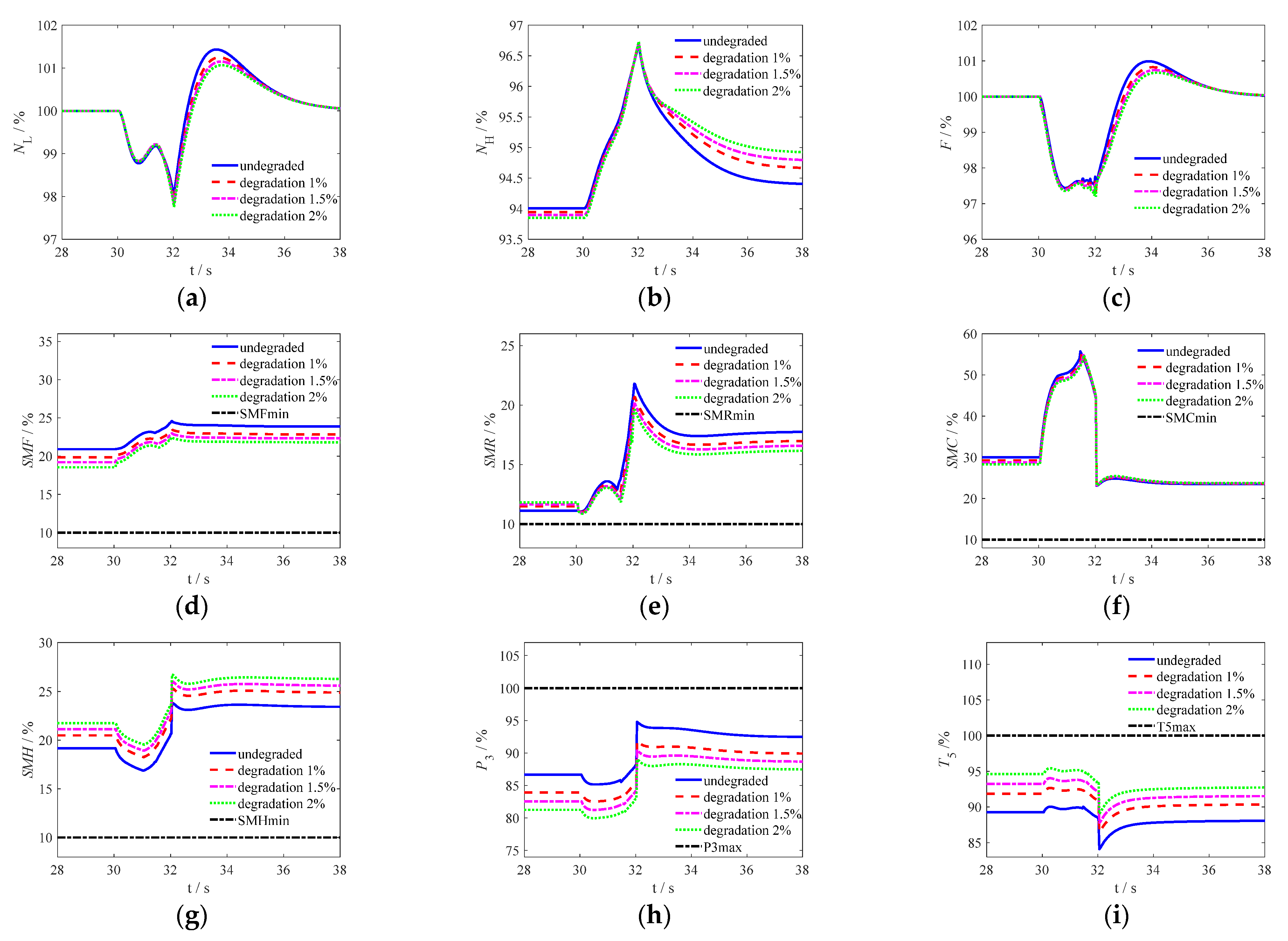
Taking the subsonic cruise point as an example, the performance degradation of the six major components of ACE, namely FFAN, RFAN, CDFS, HPC, HPT and LPT, occur simultaneously. The simultaneous degradation of 1%, 1.5%, 2% are simulated and compared with the rated engine. The responses are shown in
Figure 9, where “undegraded”, “degradation 1%”, “degradation 1.5%” and “degradation 2%” respectively represent the rated and different degradation engine, and the subscripts “min” and “max” represent the minimum and maximum limits of the corresponding variables.
It can be seen from
Figure 9d–i that under various degradation conditions, the output of the engine is far away from the constraint boundary. From
Figure 9a–c, the fluctuations of LP rotor speed
NL, HP rotor speed
NH and closed-loop thrust
F during the mode transition process are shown in
Table 1. In the table, the fluctuation represents the maximum absolute deviation of each output parameter from its final steady-state value during the mode conversion process.
According to
Table 1, it can be seen that under different performance degradation conditions of ACE, there is not much difference in the fluctuation magnitude of the output parameters of ACE. When degraded by 2%, the fluctuation of thrust is maximum, but it is still smaller than the traditional linear variation geometric mechanisms control method under rated conditions. Therefore, the results indicate that the control method for ACE mode conversion has good robustness and adaptability.
5.3. Influence of the of Bézier Curve’s Order on ACE Mode Transition
In order to compare the influence of Bézier curves of order on ACE mode conversion, the regulation schedules of open-loop geometric mechanisms constructed by Bézier curves of fourth order, fifth order, sixth order and seventh order are optimized (the computational complexity of Bézier curves increases by order with the increase of the number of control points, so the maximum order of Bézier curves selected in this paper is seven) Using the structure shown in
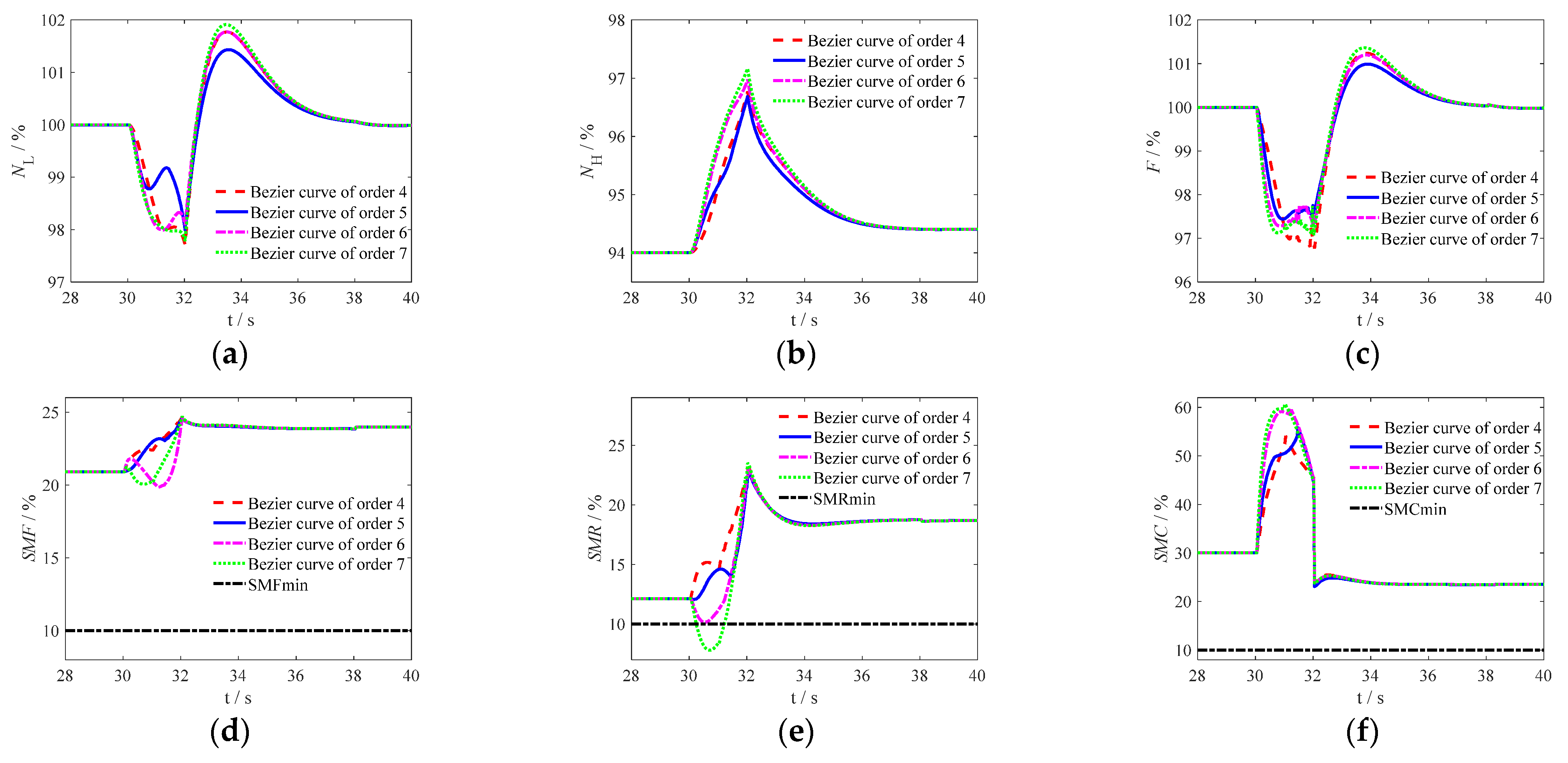
Figure 2. Taking the subsonic operating point as an example, the optimal results of different Bézier curves were used for ACE mode transition control, and the output parameters of ACE were obtained as shown in
Figure 10. Among them, “Bézier curve of order 4”, “Bézier curve of order 5”, “Bézier curve of order 6”, and “Bézier curve of order 7” respectively results obtained from different order Bézier curves respectively.
As shown in
Figure 10, from
Figure 10a–c, the fluctuations of the low-pressure rotor speed
NL, high-pressure rotor speed
NH and thrust
F of ACE are listed in
Table 2 to detail the influence of the Bézier curve’s orders.
According to
Figure 10d–i and
Table 2, the SMR at the seventh order Bézier curve optimization condition over the lower limit, so the optimization result is not acceptable. The output parameters of the engine are far from the constraint boundary under all other conditions. As the order of the Bézier curve increases, the fluctuation of ACE closed-loop output shows a trend of first decreasing and then increasing. When the order of the Bézier curve is five, the fluctuation of the ACE output is minimized, which can meet the requirements of ACE mode conversion. Moreover, the order of the fifth order Bézier curve is suitable to make the calculation simpler and reduce the burden of calculation. Therefore, it is reasonable to use a fifth order Bézier curve to construct the control schedule of the open-loop geometric mechanism in mode transition process of ACE.
6. Conclusions
In this paper, the research on mode transition control is carried out for ACE. The ALQR controller is designed to maintain thrust and LP rotor speed constant through the regulation of Wfm and A8, and based on this closed-loop control, the PSO algorithm is used to optimize the model transition control schedules of other open-loop geometric mechanisms, so as to make the change of the open-loop geometric mechanisms match with the demand of closed-loop control.
The use of Bézier curves to construct the transition state control schedule of the open-loop geometrical mechanism is a feasible method to achieve a smooth transition of the geometrical mechanism, and it is easy to optimize the geometrical structure change curves through optimizing the control points of the Bézier curves. The control system with the optimized geometrical mechanism schedules shows advantages to that of the traditional linear variation scheduling method in rotor speeds and thrust fluctuation magnitudes during the mode transition process. In addition, it was verified that the ACE mode transition control method proposed in the article has good robustness and adaptability.
Comparing the simulation results of mode transition under two flight conditions, it can also be concluded that the ACE at subsonic cruise and supersonic cruise points exhibits different economic characteristics under different operating modes. Therefore, the next step will be to study the optimal mode transition working point, in order to fully utilize the economic performance of ACE throughout the entire flight envelope.
