Article

Critical Inertia Calculation Method of Generators Using Energy Balance Condition in Power System

1
Hyosung Corporation, Anyang-si 14080, Republic of Korea
2
Department of Electrical Engineering, Jeonbuk National University, Jeonju-si 54896, Republic of Korea
3
Smart Grid Research Center, Jeonbuk National University, Jeonju-si 54896, Republic of Korea
*
Author to whom correspondence should be addressed.
Energies 2024, 17(5), 1097; https://doi.org/10.3390/en17051097
Submission received: 30 January 2024 / Revised: 13 February 2024 / Accepted: 20 February 2024 / Published: 25 February 2024
(This article belongs to the Special Issue Electrical Power System Dynamics: Stability and Control II)

Abstract

:
Critical inertia can be defined as the minimum kinetic energy stored in generators that should be kept for maintaining the frequency stability of the power system. As the frequency control performance of the power system is maintained according to its control criterion, during the inertia response time frame, the expected energy imbalance can be calculated by accumulating the imbalanced power caused by the credible contingency and calculating the available inertia response by considering the allowable operating limit of the frequency. Since the frequency control criterion can be met when the available inertia response becomes larger than the expected energy imbalance, the critical inertia can be calculated by the kinetic energy of the generators, of which the available inertia response is equal to the expected energy imbalance due to the contingency. With this in mind, this paper derives the energy balance condition for the frequency stability in the inertia response time frame based on the frequency control criterion and calculates the minimum inertia, which should be kept in the generators from the energy balance condition for meeting the criterion. In addition, the effectiveness of the proposed method is verified through various case studies employing Korean power systems.

1. Introduction

Globally, the penetration level of renewable energy sources (RESs) is rapidly in-creasing as part of an effort to reduce greenhouse gas emissions to respond to the climate crisis. In Korea, according to the Renewable Energy 3020 transition plan, the proportion of renewable energy generation would need to increase up to 20% by 2030 [1]. In order to reach the RES expansion target, it is expected that the accumulated capacity of RESs reaches 77.77 GW in 2034 according to The 9th Basic Plan for Long-term Electricity Supply and Demand [2]. Moreover, the expansion of renewable energy is expected to be accelerated by declaring carbon neutrality 2050. In order to realize carbon neutrality as of 2050, the yearly generating proportion of RESs in power systems should increase to 60.9% or 70.8%, depending on the scenarios [3]. Each scenario considers a plan to completely suspend thermal power generation or only coal power generation in the power grid sector to realize carbon neutrality. According to this plan, it is expected that the proportion of conventional synchronous generators drastically reduces in the future power grid.
Compared with synchronous generators, most RESs cannot provide an inherent inertial response to the power grid [4,5]. The inertial response provided by synchronous generators prevents a rapid frequency drop by releasing the kinetic energy stored in the rotating mass in generators when the power becomes imbalanced due to a disturbance. Without sufficient inertia support, extreme frequency fluctuations may occur in the early stages of a disturbance when the power imbalance occurs; further, it can affect the frequency control performance, eventually threatening the frequency stability [6,7,8]. Therefore, it is necessary to maintain the inertia of power systems above a certain level in order to secure the frequency stability of the power systems even in a situation where the penetration of RESs greatly increases when reducing greenhouse gas emission. The minimum level of inertia required for a secure frequency stability is called critical inertia. In order to secure the stability of a power system, it is necessary to calculate the critical inertia and apply it to the operation of the power system as one of the limits.
As the penetration of renewable energy has increased, many studies have been conducted on methods of evaluating or calculating the minimum level of inertia required to maintain the stability of power systems. In [9], the minimum inertia requirement was assessed by evaluating the frequency response by simulating three asynchronous generator penetration conditions as a frequency control constraint of an electric power market model. The authors of [10] evaluated the frequency response according to the RES penetration scenarios of the European power system in 2050 and calculated the additional inertia requirement to maintain the frequency stability through a quantitative analysis. In [11], a study was conducted to apply the rate of change of frequency (RoCoF) constraint to the dispatch scenario according to the European Network of Transmission System Operators for Electricity (ENTSO-E) visions and to analyze the inertia that must be secured for each synchronous area in Europe. In [12], an algorithm was proposed to estimate the minimum inertia required to fulfil the ENTSO-E requirements for RoCoF values and assessed minimum inertia under a relevant variety of imbalanced conditions through an extensive frequency response and inertia analysis.
Power-system-operating organizations have also suggested a method of calculating the minimum inertia required for a stable power system operation that operates the power system by securing inertia accordingly. In [13], the critical inertia determination method is proposed based on a regression curve derived from the relationship between inertia and the time required to guarantee the activation of the responsive reserve service (RRS) through high-set underfrequency relays (UFRs). In [14], the inertia requirements methodology is proposed to calculate the inertia requirements for each inertia sub-network. The optimum point is derived by considering the relationship between the inertia secured in the power-system-operating conditions and the availability and requirement of frequency control resources to guarantee frequency stability. However, those studies relied on complicated iterations or massive simulations to calculate the critical inertia. Especially in the case of national-scale simulation analyses of power systems, the critical inertia calculation may not be possible because of limitations in database construction and the complexity of systems.
With this in mind, this paper proposes the critical inertia calculation method, which is theoretically credited, intuitive and objective, since it is derived by using the energy balance condition of the power system based on its frequency control criterion. In the proposed method, the critical inertia is calculated by the amount of the kinetic energy of the generators, of which the available inertia response is equal to the expected energy imbalance due to the contingency, which is a marginal condition for meeting the frequency control criterion. Therefore, the novelty of the proposed method lies in the fact that it directly calculates critical inertia using the operating criterion and typical characteristics of the power system without complicated simulations. For this, the energy balance condition is derived in the inertia response time frame based on the frequency control criterion, and the minimum amount of inertia that should be kept in the synchronous generators is calculated from the energy balance condition for meeting the criterion. In addition, the effectiveness of the proposed method is verified through various case studies employing a Korean power system.
The remainder of this paper is organized as follows: In Section 2, the inertia response in power system frequency control and critical inertia is analyzed. Section 3 proposes the critical inertia calculation method using the energy balance condition of a power system. In Section 4, a case study is conducted and feasibility is verified by applying the proposed critical inertia calculation method to a Korean power system. Finally, this paper is concluded in Section 5.

2. Critical Inertia in Power System Frequency Control

2.1. Inertia Response in Power System Frequency Control

Since the top priority of the power system operation is a stable power supply, the power system operator must ensure that the frequency, which is an indicator of the balance of power supply and demand, is maintained within the rated range. In order to achieve this, the operating reserve is secured and utilized for real-time system operation in stages, so that a stable power supply can be achieved even in the event of the loss of generation (LoG). After the disturbance, the primary frequency control is performed following the governor characteristics of individual generators to prevent a frequency drop and to restore the frequency to a quasi-steady state frequency. Then, the secondary and tertiary reserves operate in sequence to restore the frequency to a steady state and complete the frequency control, as shown in Figure 1 [15,16].
The inertial response suppresses frequency fluctuations in the early stages of a disturbance, in which the frequency decreases before the primary frequency control is normally activated. This action is caused by the released kinetic energy stored in the rotating mass of a synchronous generator through the power generation principle, and it is an inherent characteristic that is secured without additional control methods in a power system centered on a synchronous generator. The inertial response contributes to the frequency control during the time it takes for the fastest frequency control of the power system to be activated normally.
In a power system based on a synchronous generator with sufficient inertial energy, the system inertia effectively suppresses the sudden frequency drop until the frequency control is activated normally once again after a disturbance. However, the inertial response performance is expected to be significantly degraded, because the RES’s penetration in the power system increases extensively [17]. In a RES-based power system, the inherent inertia support is insufficient, and the frequency rapidly drops before the frequency control can be normally activated. In the end, even if a sufficient operating reserve is secured, the performance criterion of frequency stability can be violated due to the shortage of inertia. Therefore, in order to maintain frequency stability in future power systems centered on renewable energy, a sufficient inertial response must also be secured along with existing frequency control resources.

2.2. Definition and Importance of Critical Inertia

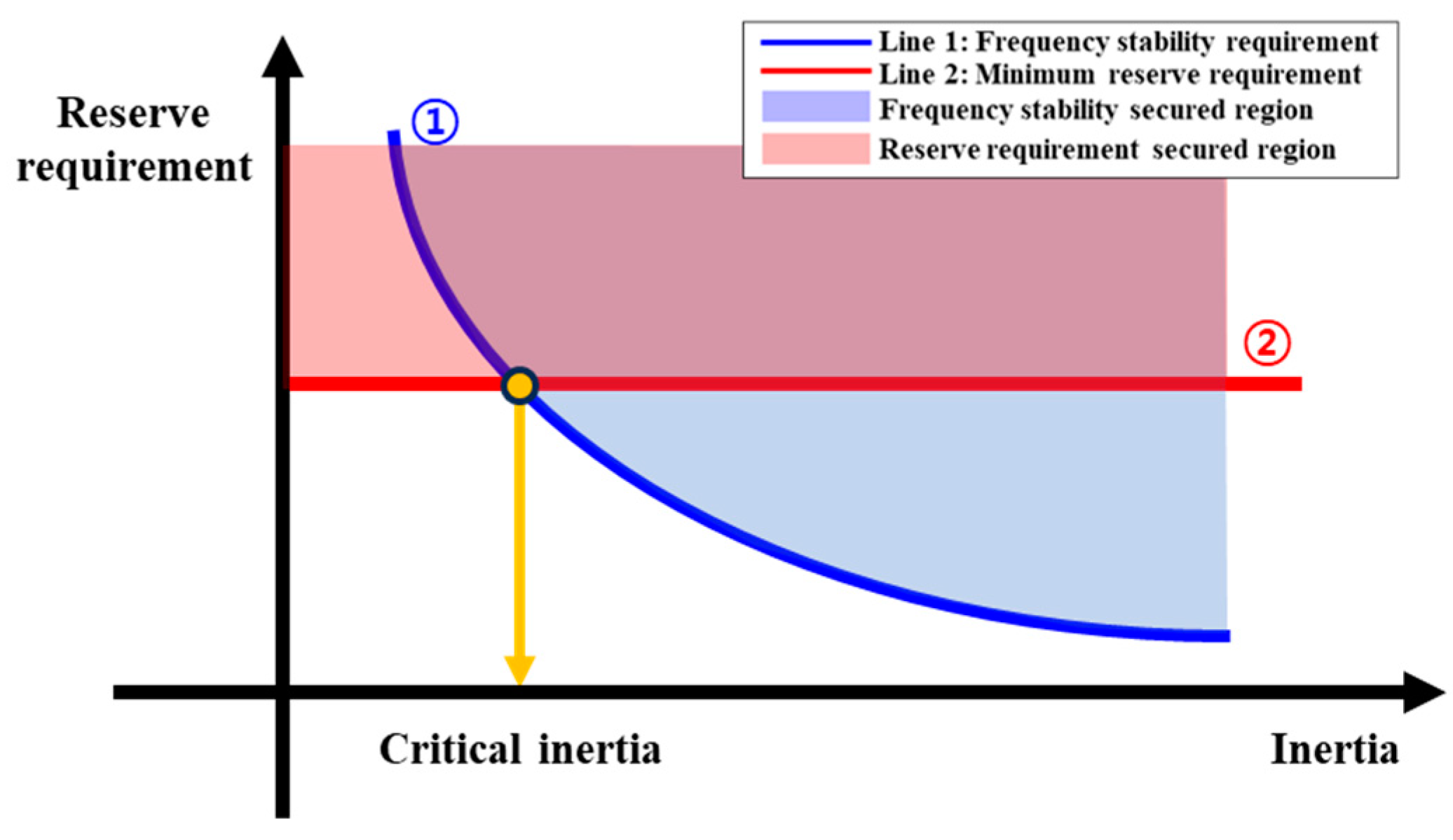
In the early stages of a disturbance, the instantaneous power imbalance is compensated for by an inertial response which is the power automatically extracted from the energy stored in the rotating mass of a synchronous generator [18]. As a result of the inertial response, the rotating masses of generators lose their speed; that is, the frequency of the power system decreases. The primary frequency control is triggered by the frequency deviation from the automatic governor response proportional to the frequency deviation with a speed droop characteristic. As time goes by, the proportion of the inertial response in the total response decreases. In this process, when a disturbance occurs, the inertial response is displaced by the primary frequency control. However, there is a delay between the frequency drop and the governor’s response due to the large time constant of the governor’s mechanical action. Therefore, the lower the inertia system, the more the frequency drops until the primary frequency control can be normally activated; thus, there is a possibility of violating the criterion of the frequency stability of the power system even though a sufficient primary reserve was secured. In this regard, in order to secure frequency stability, it is necessary to manage the inertia of the power system, as well as the operating reserve for frequency control. In terms of maintaining the frequency within an allowable range, a complementary relationship needs exists between the amount of inertia and the operating reserve [17,19]. The less inertia is secured, the more operating reserve is required to keep the frequency above the stability threshold and vice versa. However, the operating reserve is secured regardless of the inertia, since its purpose is to ensure the reliability of the power supply and demand. Thus, the critical inertia is defined as the minimum inertia that ensures frequency stability with the predetermined amount of the operating reserve. Figure 2 shows the inertia-dependent operating reserve requirement and the condition of critical inertia.
Line one indicates the minimum required amount of reserve required to satisfy the frequency control performance criterion with a given inertia level, and in its upper region, the frequency is managed within the allowable range even in the case of a disturbance. Line two is the minimum reserve requirement, which is the power the system operator must secure. Therefore, the critical inertia is determined based on the frequency response performance at the intersection of lines one and two, where the frequency stability is secured with the minimum reserve requirement.
However, it is difficult to mathematically quantify the effect of a power system’s inertia on frequency nadir in large-scale systems. In existing studies, the minimum inertia level that satisfies the frequency control performance criterion was derived through repeated simulations while changing the inertia conditions of the power systems. This paper presents a method to calculate critical inertia without repeated simulations using the relationship between the inertial response energy and frequency control performance criterion in the credible contingency condition.

3. Proposed Critical Inertia Calculation Method

3.1. Reinterpretation of Critical Inertia Using Energy Balance Condition of Power Systems

The frequency dynamics of a power system are represented by Equation (1), known as the swing equation [20].
2 H d ω d t = P a
where H is the inertia constant, ω is the rotational speed of the generator and P a is the acceleration power or the imbalanced power of the power system. After the disturbance occurs, the imbalanced power accumulates over time, and can be reformulated by integrating both sides of Equation (1) as follows:
E k t E k t 0 = t 0 t P a t     d t
Δ E k = E i m b .    
where E i m b . is the imbalanced energy caused by the disturbance in the power system and Δ E k is the amount of change in the kinetic energy of the synchronous generators to compensate for the imbalanced energy in the power system. That is, in the event of a LoG, the energy stored in the rotating mass of the generator is released to equal the imbalanced energy in the power system.
If the available kinetic energy is larger than the maximum imbalanced energy in the power system, the imbalanced energy can be compensated for within the kinetic energy stored in the generators. In this regard, the stable condition of a power system can be represented as Equation (4).
E a v a i l , I R   E i m b , M A X    
where E a v a i l , I R is the available energy as the inertial response and E i m b , M A X is the maximum imbalanced energy in the power system. The critical inertia of the power system can be determined under the energy balance condition, in which the available kinetic energy is equal to the maximum imbalanced energy of the power system. However, the amount of the kinetic energy of generators is finite, following the number of infeed generators and their operating conditions. It is available only within a restricted range according to the power system’s operating regulations. In compliance with operating regulations, the frequency control performance criterion can be met when the available inertia response is larger than the maximum energy imbalance caused by the contingency, as shown in Figure 3.
Under the condition that the same E i m b . occurs in the power system, the critical inertia by frequency control performance is determined with the condition that the frequency nadir is equal to the frequency stability criterion, as shown in Figure 3a. Converting the preceding conditions into energy relationships is expressed in Figure 3b. E a v a i l , I R is limited by the frequency stability criterion, and critical inertia can be calculated when the energy balance condition is achieved in Equation (4).

3.2. Kinetic Energy Availability under the Critical Condition of Frequency Stability

The available kinetic energy of generators to compensate for the imbalanced energy can be limited by an allowable frequency range specified in the power system’s operation regulations. Since the inertial response is provided by the rotating mass reducing its own rotational speed, the amount of available energy to provide an inertial response is limited according to the frequency control performance criterion of the power system.
The kinetic energy of rotating mass is proportional to the square of the rotational speed according to the definition of the rotational kinetic energy, shown as Equation (5).
E k = 1 2 J ω 2
The energy released as the inertial response due to the change in the power system frequency can be derived as Equation (6).
E I R = E k 0 1 f 2 f 0 2
where E I R is the released energy as the inertial response, E k 0 is the kinetic energy of the generator in the steady state, f 0 is the nominal frequency and f is the system frequency. If the rotational speed of the generator is limited by the frequency control performance criterion of the power system, the maximum available energy in the total kinetic energy stored in the generator is determined using Equation (7).
E a v a i l , I R , M A X = E k 0 1 f t h r e s . 2 f 0 2
where E a v a i l , I R , M A X is the maximum available kinetic energy of the generators as the inertial response and f t h e r e s . is the allowable system frequency threshold determined by the frequency control performance criterion. The relationship between the secured amount of kinetic energy and the available capacity is determined by the frequency stability criterion, and it is derived as the kinetic energy availability ( k C I ) in Equation (8).
k C I = 1 f t h r e s . 2 f 0 2

3.3. Imbalanced Energy Calculation

In the event of a sudden LoG, the balance of the power supply and demand becomes disrupted. In the case of a LoG, the power system has a frequency control system in preparation for the credible contingency to guarantee the reliability of the power supply. In addition, the power imbalance can be partially mitigated on the power demand side as well. The loads in the power system can passively provide a response that alleviates the power imbalance according to its own characteristics [21]. Therefore, the imbalanced power consists of three main components, as shown in Equation (9).
P i m b = P L o G Δ P l o a d + P P F R  
where P L o G is the amount of LoG, Δ P l o a d is the response of the loads that passively react to the LoG and P P F R is the power raised by the primary frequency reserve that provides the fastest response service in the operating reserve. Also, although the influence of the LoG may lead to changes in the active power loss, the impact of the change in the active power loss is assumed to be negligible, since the amount of the LoG considering the N − 1 contingency is quite small compared to the scale of the national power system.
The load of the power system has the effect of temporarily reducing the size of the contingency in response to disturbances. The dynamic characteristics of the load in the power system are represented as voltage-dependent and frequency-dependent types [22]. These load characteristics are generally distributed throughout the power system and determined depending on the scale and industrial characteristics of the power system. The load response should be considered in the imbalanced energy calculation, since it has a great influence on the determination of the power balance point in the transient state as the scale of the power system increases.
P P F R is determined by the frequency control performance of the power system. It generally contributes to forming a new balance point of power supply and demand in the transient state by providing the generator power control proportional to the frequency deviation using a governor. Since the power system operator has the stipulated operating reserve for the frequency control, it is modeled as the primary reserve that responds in the credible contingency according to the operating reserve’s performance regulations.
Since the credible contingency in power systems is generally predetermined, it can be seen that the response of the three elements of power imbalance can also be determined according to the frequency control performance criterion of the operating reserve’s performance regulations. Therefore, it is possible to model the imbalanced power by using the operating regulations of the power system.
The energy imbalance of the power system is the cumulative amount of imbalanced power over time in a credible contingency. The imbalanced power is resolved in consideration of the primary frequency control and the load response. Due to these responses, the imbalanced power decreases and the energy imbalance becomes the maximum at t n a d i r , where the imbalanced power ( P i m b ) first becomes zero after the LoG. This imbalanced energy, calculated using Equation (10), should be compensated for with the kinetic energy stored in the generator.
E i m b , M A X = t 0 t n a d i r P L o G Δ P l o a d + P P F R d t  

3.4. Calculation of Critical Inertia Using the Energy Balance Condition of the Power System

According to the condition of Equation (4), the maximum available kinetic energy of the generator must be larger than the energy in order for the power system to satisfy the frequency control performance criterion of the power system. Then, Equation (4) can be reformulated as Equation (11), the kinetic energy requirement in the steady state by the stable condition of the power system from the viewpoint of energy balance.
E k 0 1 k C I     × E i m b
According to the definition of critical inertia, the minimum E k 0 in Equation (11) is the critical inertia and its condition is represented as Equation (12).
E C r i t i a l = 1 k C I       × E i m b .
where E C r i t i c a l is the critical inertia of the power system. However, this critical inertia is calculated based on the generators remaining in the power system after the contingency. Since the operation and monitoring of the power system is based on conditions before the contingency, the minimum inertia for operation E O p r . M i n . of the power system includes the inertia of the tripped generator.
E O p r . M i n . = E C r i t i a l + E t r i p
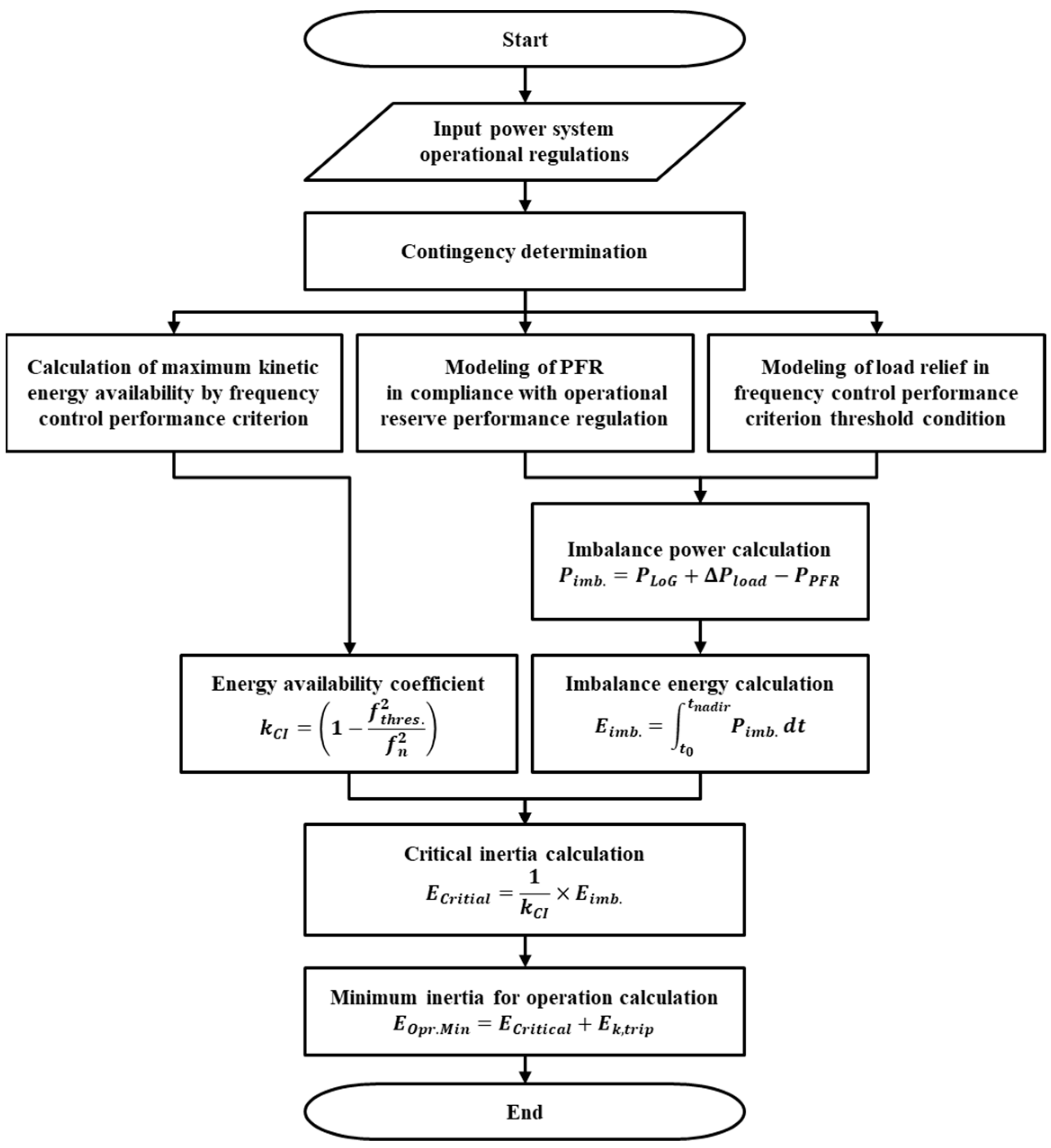
In order to calculate the critical inertia using the proposed method, formal information, such as the frequency control performance criterion, the amount of LoG, primary frequency reserve performance and load characteristics, is required and is generally specified in the operating regulations of the power system. The proposed critical inertia calculation method was summarized as a flowchart, as shown in Figure 4.

4. Case Study

In the case study, the critical inertia was calculated by applying the proposed method to the Korean power system, and the effectiveness of the critical inertia calculation method was verified through a frequency response performance evaluation.
First, the operating regulations for the frequency control performance of the Korean power system were as follows: The frequency control performance criterion of the Korean power system was stipulated in the power system reliability and electricity quality control performance criterion announced by the Ministry of Trade, Industry and Energy (MOTIE). The frequency should be maintained within the specified range in a given system state, as shown in Table 1 [23].
In order to comply with the frequency control performance criterion in Table 1, the Korea power exchange (KPX), the power system and market operator of Korea, secures the operating reserve for frequency control when operating the power system [24].

4.1. Critical Inertia Calculation Using the Proposed Method

The critical inertia was calculated under the condition of the N − 1 contingency because the amount of primary reserve is designed against the N − 1 contingency in Korean power systems.

4.1.1. Calculation of Maximum Availability of Kinetic Energy

The amount of kinetic energy released by the frequency drop was expressed by Equation (8). Table 2 shows the maximum availability of kinetic energy for each system state by applying the frequency control performance threshold for each system state corresponding to the frequency control performance criterion to Equation (8). In the N − 1 contingency condition, the maximum available amount of kinetic energy was only 1% of the total energy stored in the rotating mass of generators before the contingency. Since frequency is an indicator of the balance of the power supply and demand, the performance criterion of frequency is inevitably very conservative, so only a very small amount of energy is available compared to the total energy stored.

4.1.2. Imbalanced Energy in Power System Caused by LoG

The imbalanced energy in the power system was calculated by modeling each element constituting the imbalance power under the N−1 contingency condition. The components of the imbalanced power should consider the extent of the generator trip, load relief and frequency control performance, which contribute to the formation of the frequency nadir.
The amount of credible contingency was the largest single generation loss in the power system, so it was determined as a constant. Since the performance of the operating reserve and load relief included non-linear characteristics, it was possible to calculate the critical inertia by sufficiently considering the characteristics of the power system by using the historical data of the power system. However, since there were difficulties in the securing data, in this study, the critical inertia was calculated by modeling each response based on a planning database of the Korean power system based on Power System Simulator for Engineering (PSS/E 33.12.2).
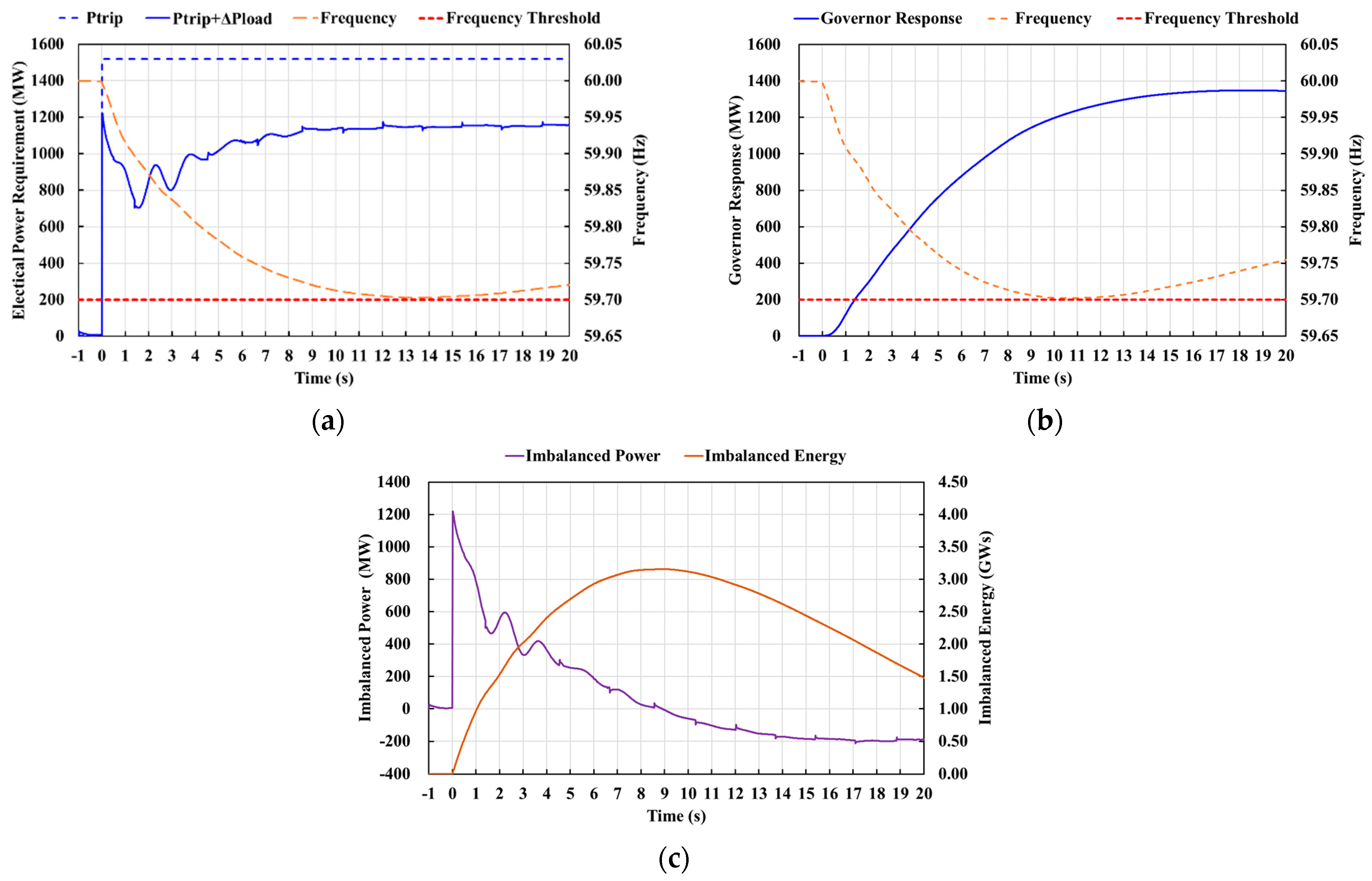
The load relief component considers both the voltage- and frequency-dependent characteristics. The voltage-dependent characteristic was modeled as a ZIP load, and the ratio of each component was suggested in the Korean Electricity Market Rule [24]. The frequency-dependent component of the load was modeled using the LDFRAL model, the load frequency model provided by the PSS/E library, and its characteristic constants were applied as 1.6611, as suggested by KPX. Considering these load characteristics, the net disturbance for the power system at the threshold level of frequency stability was derived as shown in Figure 5a. Although a 1520 MW generator trip occurred, in the transient state of the disturbance, the amount of the net active power requirement for the in-feed generators of the power system was reduced by the load relief due to voltage and frequency fluctuations.
Next, the primary reserve performance modeling was performed according to the operating reserve performance criterion. The primary reserve of 1000 MW was secured by the governor response of the synchronous generator fed to the power system in compliance with the primary reserve security regulations of the Korean power system. In this condition, the governor response was derived from the frequency stability threshold condition, as shown in Figure 5b.
Finally, the imbalanced energy was calculated by synthesizing the previous modeling results. Figure 5c shows the imbalance power and the accumulated imbalanced energy by using the components of the imbalance power modeled through the preceding series of processes. The power imbalance was represented by the sum of the amount of LoG, the load response and the primary frequency response. This power imbalance accumulated over time and became an energy imbalance. At the point when the power imbalance became zero, the maximum value of the imbalanced energy 3.156 GWs was derived.

4.1.3. Critical Inertia Calculation

In the case of an N − 1 contingency in the Korean power system, the maximum value of imbalanced energy in the power system was derived as 3.156 GWs. In order to compensate for this imbalanced energy by considering 1% of the kinetic energy availability, according to Table 2, energy corresponding to 100 times the imbalanced energy must be held in the steady state, so the critical inertia was derived as 315.66 GWs. However, since this critical inertia was calculated based on the generators remaining in the power system after the N-1 contingency, the minimum inertia of operation was 323.88 GWs, including the tripped generator. The results of the critical inertia calculation are summarized in Table 3.

4.2. Verification of Proposed Method

The effectiveness of the proposed method was verified through a frequency response performance evaluation based on the dynamic simulation of the Korean power system using Power System Simulator for Engineering (PSS/E). Since the RESs’ penetration in power systems is expected to increase for reducing greenhouse gas emissions, the thermal power generators would be replaced with RESs without inertia in this scenario to simulate the critical inertia condition. Figure 6 and Table 4 show the frequency response performance in the critical inertia condition derived using the proposed method.
The frequency response performance evaluation was performed under different load level conditions. All of them met the frequency control performance criterion within a 41 mHz frequency deviation. It was confirmed that the critical inertia calculated based on the operation regulations of the power system and the performance regulations of the operating reserve could guarantee a frequency response performance above the frequency performance criterion, and it can be expected to be applied as a standard for maintaining inertia when operating power systems. Thus, the effectiveness of the proposed critical inertia calculation method was verified.

5. Conclusions

This paper proposed a critical inertia calculation method using the energy balance condition of a power system. Intuitive requirements for critical inertia were derived by reinterpreting the power system frequency stability limit condition as an energy balance condition. The imbalanced energy that could appear in the frequency stability limit condition was calculated by modeling the dominant components of the imbalance power of the power system according to the power system operation regulations, and a method of deriving critical inertia, which is the minimum amount of energy stored in the rotating mass of generators that can compensate for imbalanced energy, was proposed from the energy balance relationship.
The effectiveness of the proposed method was verified by calculating the critical inertia for a Korean power system. In the condition of the N-1 contingency in a Korean power system, the availability of kinetic energy of generators was derived as only 1% of the total kinetic energy stored in generators. Imbalanced energy was calculated under the same conditions through imbalanced power modeling considering the power system’s operational regulations. In the energy balance condition, the critical inertia was calculated as 323.88 GWs. In addition, it was confirmed that the critical inertia calculated by the proposed method could guarantee the frequency stability of the power system even at different load levels. Therefore, the critical inertia calculated by the proposed method could be used as a representative value of the critical inertia under various operating conditions of power systems, and the effectiveness of the proposed method was verified.
Furthermore, the critical inertia calculation method proposed in this paper provided a link between the operational regulations of power systems and the criterion securing minimum inertia by using the criteria of the frequency control and operating reserve performance as the criterion for calculating the critical inertia. In addition, it is expected that the proposed method considers additional frequency control resources in future power systems, such as governor responses in the imbalanced energy calculation. Thus, the proposed method could help to calculate the critical inertia without complicated iterative simulations under various system-operating conditions.
In this work, we proposed a critical inertia calculation method based on the operating criterion of the power system. In future works, we plan to apply the critical inertia calculation method proposed in this paper to various power system conditions by considering the additional trip of RESs through a frequency relay and various frequency response resources, such as energy storage systems or a demand response.

Author Contributions

Conceptualization, J.-Y.Y.; methodology, J.-Y.Y. and K.S.K.; software, J.-Y.Y. and Y.H.S.; validation, J.-Y.Y., Y.H.S. and K.S.K.; formal analysis, J.-Y.Y., Y.H.S. and K.S.K.; investigation, J.-Y.Y., Y.H.S. and K.S.K.; resources, K.S.K.; data curation, J.-Y.Y.; writing—original draft preparation, J.-Y.Y. and K.S.K.; writing—review and editing, K.S.K., J.-Y.Y. and Y.H.S.; visualization, K.S.K., J.-Y.Y. and Y.H.S.; supervision, K.S.K.; project administration, K.S.K.; funding acquisition, K.S.K., J.-Y.Y. and Y.H.S. All authors have read and agreed to the published version of the manuscript.

Funding

This work was partially supported by Korea Institute of Energy Technology Evaluation and Planning(KETEP) grant funded by the Korea government(MOTIE) (20224000000440, Sector coupling energy industry advancement manpower training program). This work was also partially supported by Korea Institute of Energy Technology Evaluation and Planning(KETEP) grant funded by the Korea government(MOTIE) (20228510070050, Development and Demonstration of Safety Reinforced K-BESS for entry into the Nordic Market).

Data Availability Statement

Data are contained within the article.

Conflicts of Interest

Author Jae Young Yang was employed by the company Hyosung Corporation. The remaining authors declare that the research was conducted in the absence of any commercial or financial relationships that could be construed as a potential conflict of interest.

References

  1. Ministry of Trade, Industry and Energy (MOTIE) (South Korea). Renewable Energy 3020 Plan, 2017. Available online: https://www.motie.go.kr/kor/article/ATCL3f49a5a8c/159996/view (accessed on 13 February 2024).
  2. Ministry of Trade, Industry and Energy (MOTIE) (South Korea). The 9th Basic Plan for Long-Term Electricity Supply and Demand (2020–2034), 2020. Available online: https://www.motie.go.kr/kor/article/ATCLf724eb567/210325/view (accessed on 13 February 2024).
  3. Joint with Related Ministries of South Korea. 2050 Carbon Neutral Scenario, 2021. Available online: https://www.2050cnc.go.kr/base/board/read?boardManagementNo=26&boardNo=101&menuLevel=2&menuNo=63 (accessed on 13 February 2024).
  4. European Network of Transmission System Operators for Electricity (ENTSO-E). Nordic Report Future System Inertia V2. 2018. Available online: https://docs.entsoe.eu/en/dataset/nordic-report-future-system-inertia/resource/6efce80b-2d87-48c0-b1fe-41b70f2e54e4 (accessed on 13 February 2024).
  5. Fernandez-Guillamon, A.; Gomez-Lazaro, E.; Muljadi, E.; Molina-Garcia, A. Power systems with high renewable energy sources: A review of inertia and frequency control strategies over time. Renew. Sustain. Energy Rev. 2019, 115, 109369. [Google Scholar] [CrossRef]
  6. National Renewable Energy Laboratory (NREL). Inertia and the Power Grid: A Guide Without the Spin. 2020. Available online: https://www.nrel.gov/news/program/2020/inertia-and-the-power-grid-a-guide-without-the-spin.html (accessed on 13 February 2024).
  7. Australian Energy Market Operator (AEMO). Renewable Integration Study Stage 1. 2020. Available online: https://aemo.com.au/energy-systems/major-publications/renewable-integration-study-ris (accessed on 13 February 2024).
  8. European Network of Transmission System Operators for Electricity (ENTSO-E). Requirement for Minimum Inertia in the Nordic Power System. 2021. Available online: https://en.energinet.dk/media/q1ulbrdk/requirement-for-minimum-inertia-in-the-nordic-power-system-2021.pdf (accessed on 13 February 2024).
  9. Ahmadyar, A.S.; Riaz, S.; Verbic, G.; Riesz, J.; Chapman, A. Assessment of Minimum Inertia Requirement for System Frequency Stability. In Proceedings of the 2016 IEEE International Conference on Power System Technology (Powercon), Wollongong, Australia, 28 September–1 October 2016. [Google Scholar] [CrossRef]
  10. Agathokleous, C.; Ehnberg, J. A Quantitative Study on the Requirement for Additional Inertia in the European Power System until 2050 and the Potential Role of Wind Power. Energies 2020, 13, 2309. [Google Scholar] [CrossRef]
  11. Mehigan, L.; Al Kez, D.; Collins, S.; Foley, A.; O’Gallachoir, B.; Deane, P. Renewables in the European power system and the impact on system rotational inertia. Energy 2020, 203, 117776. [Google Scholar] [CrossRef]
  12. Fernandez-Guillamon, A.; Gomez-Lazaro, E.; Molina-Garcia, A. Extensive frequency response and inertia analysis under high renewable energy source integration scenarios: Application to the European interconnected power system. IET Renew. Power Gen. 2020, 14, 2885–2896. [Google Scholar] [CrossRef]
  13. Electric Reliability Council of Texas (ERCOT). Inertia: Basic Concepts and Impacts on the ERCOT Grid. 2018. Available online: https://www.ercot.com/files/docs/2018/04/04/Inertia_Basic_Concepts_Impacts_On_ERCOT_v0.pdf (accessed on 13 February 2024).
  14. Australian Energy Market Operator (AEMO). Inertia Requirements Methodology Inertia Requirements & Shortfalls. 2018. Available online: https://www.aemo.com.au/-/media/files/electricity/nem/security_and_reliability/system-security-market-frameworks-review/2018/inertia_requirements_methodology_published.pdf (accessed on 13 February 2024).
  15. Lawrence Berkeley National Laboratory (LBNL). Use of Frequency Response Metrics to Assess the Planning and Operating Requirements for Reliable Integration of Variable Renewable Generation. 2010. Available online: https://www.ferc.gov/sites/default/files/2020-05/frequencyresponsemetrics-report.pdf (accessed on 13 February 2024).
  16. North American Electric Reliability Corporation (NERC). Fast Frequency Response Concepts and Bulk Power System Reliability Needs. 2020. Available online: https://www.nerc.com/comm/PC/InverterBased%20Resource%20Performance%20Task%20Force%20IRPT/Fast_Frequency_Response_Concepts_and_BPS_Reliability_Needs_White_Paper.pdf (accessed on 13 February 2024).
  17. Melbourne Energy Institute (MEI) University of Melbourne. Power System Security Assessment of the Future National Electricity Market. 2017. Available online: https://www.dcceew.gov.au/sites/default/files/documents/power-system-security-assessment-future-nem.pdf (accessed on 13 February 2024).
  18. Bian, Y.K.; Wyman-Pain, H.; Li, F.R.; Bhakar, R.; Mishra, S.; Padhy, N.P. Demand Side Contributions for System Inertia in the GB Power System. IEEE Trans. Power Syst. 2018, 33, 3521–3530. [Google Scholar] [CrossRef]
  19. Rezkalla, M.; Pertl, M.; Marinelli, M. Electric power system inertia: Requirements, challenges and solutions. Electr. Eng. 2018, 100, 2677–2693. [Google Scholar] [CrossRef]
  20. Prabha, K. Power System Stability and Control, 1st ed.; McGraw-Hill: New York, NY, USA, 1994; pp. 128–138. [Google Scholar]
  21. North American Electric Reliability Corporation (NERC). Frequency Response Standard Background Document. 2012. Available online: https://www.nerc.com/pa/Stand/Project%20200712%20Frequency%20Response%20DL/Bal-003-1-Background_Document-Clean-2013_FILING.pdf (accessed on 13 February 2024).
  22. Arif, A.; Wang, Z.Y.; Wang, J.H.; Mather, B.; Bashualdo, H.; Zhao, D.B. Load Modeling—A Review. IEEE Trans. Smart Grid 2018, 9, 5986–5999. [Google Scholar] [CrossRef]
  23. Ministry of Trade, Industry and Energy (MOTIE) (South Korea). Power System Reliability and Electricity Quality Maintenance Criterion, 2019. Available online: https://www.motie.go.kr/kor/article/ATCL0c554f816/64353/view (accessed on 13 February 2024).
  24. Korea Power Exchange (KPX). Korean Electricity Market Rule, 2021. Available online: https://new.kpx.or.kr/board.es?mid=a10205010000&bid=0030&act=view&list_no=71450 (accessed on 13 February 2024).
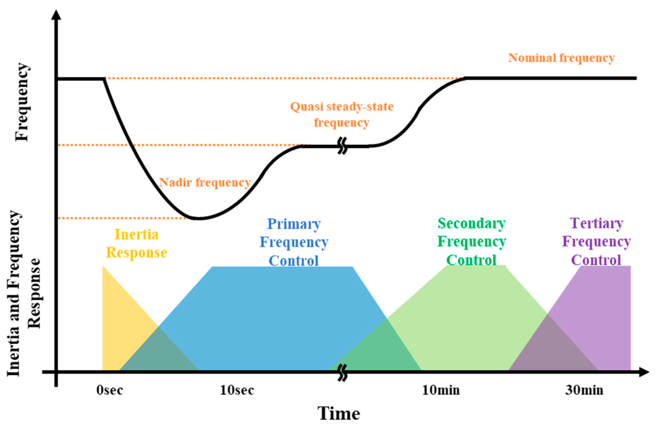
Figure 1. The sequential actions of inertia response, primary, secondary and tertiary frequency controls.
Energies 17 01097 g001
Figure 2. Inertia-dependent frequency response requirement and condition of critical inertia.
Energies 17 01097 g002
Figure 3. Critical inertia determination by (a) frequency control performance and (b) energy balance condition.
Energies 17 01097 g003
Figure 4. Flowchart of the proposed critical inertia calculation method.
Energies 17 01097 g004
Figure 5. Imbalanced energy calculation: (a) net electrical power requirement considering the load relief effect in critical condition; (b) governor response in critical condition; (c) imbalanced power and energy under N − 1 contingency condition.
Energies 17 01097 g005
Figure 6. Frequency response performance in critical inertia condition of: (a) load level: 60%; (b) load level: 80%; (c) load level: 100%.
Energies 17 01097 g006
Table 1. Frequency control performance criteria of the Korean power system.
Power System StateFrequency Control Performance Criteria
Steady state(60 ± 0.2) Hz
Loss of the largest generatorMaintained at least 59.7 Hz
Restored to 59.8 Hz within 1 min
Simultaneous loss of the two generators or SPS activationMaintained at least 59.2 Hz
Restored to 59.5 Hz within 1 min
Restored to 59.8 Hz within 10 min
Table 2. Maximum kinetic energy availability in the Korean power system.
Power System StateFrequency Control Performance Threshold
(Hz)
Nominal
Frequency
(Hz)
k C I
(%)
Steady state59.8600.67
Loss of the largest generator59.7601.00
Simultaneous loss of the two generators or SPS activation59.2602.65
Table 3. Results of critical inertia calculation.
IndicesValues
k C I 0.01
t n a d i r 8.90 s
E i m b . , M A X 3.156 GWs
E k , C r i t i c a l 315.66 GWs
E k , O p r . M i n . 323.88 GWs
Table 4. Frequency response performance by power system load levels.
Load LevelInertia (GWs)Nadir Frequency (Hz)
60%316.9459.732
80%316.9559.741
100%316.4759.705
Disclaimer/Publisher’s Note: The statements, opinions and data contained in all publications are solely those of the individual author(s) and contributor(s) and not of MDPI and/or the editor(s). MDPI and/or the editor(s) disclaim responsibility for any injury to people or property resulting from any ideas, methods, instructions or products referred to in the content.