Article

Estimation of an Extent of Sinusoidal Voltage Waveform Distortion Using Parametric and Nonparametric Multiple-Hypothesis Sequential Testing in Devices for Automatic Control of Power Quality Indices

by
Aleksandr Kulikov
1,
Pavel Ilyushin
2,*,
Aleksandr Sevostyanov
1,
Sergey Filippov
2 and
Konstantin Suslov
3,4
1
Department of Electroenergetics, Power Supply and Power Electronics, Nizhny Novgorod State Technical University n.a. R.E. Alekseev, 603950 Nizhny Novgorod, Russia
2
Department of Research on the Relationship between Energy and the Economy, Energy Research Institute of the Russian Academy of Sciences, 117186 Moscow, Russia
3
Department of Hydropower and Renewable Energy, National Research University “Moscow Power Engineering Institute”, 111250 Moscow, Russia
4
Department of Power Supply and Electrical Engineering, Irkutsk National Research Technical University, 664074 Irkutsk, Russia
*
Author to whom correspondence should be addressed.
Energies 2024, 17(5), 1088; https://doi.org/10.3390/en17051088
Submission received: 17 January 2024 / Revised: 9 February 2024 / Accepted: 22 February 2024 / Published: 24 February 2024
(This article belongs to the Topic Intelligent Control in Smart Energy Systems)

Abstract

:
Deviations of power quality indices (PQI) from standard values in power supply systems of industrial consumers lead to defective products, complete shutdown of production processes, and significant damage. At the same time, the PQI requirements vary depending on the industrial consumer, which is due to different kinds, types, and composition of essential electrical loads. To ensure their reliable operation, it is crucial to introduce automatic PQI control devices, which evaluate the extent of distortion of the sinusoidal voltage waveform of a three-phase system. This allows the power dispatchers of grid companies and industrial enterprises to quickly make decisions on the measures to be taken in external and internal power supply networks to ensure that the PQI values are within the acceptable range. This paper proposes the use of an integrated indicator to assess the extent of distortion of the sinusoidal voltage waveform in a three-phase system. This indicator is based on the use of the magnitude of the ratio of complex amplitudes of the forward and reverse rotation of the space vector. In the study discussed, block diagrams of algorithms and flowcharts of automatic PQI control devices are developed, which implement parametric and nonparametric multiple-hypothesis sequential analysis using an integrated indicator. In this case, Palmer’s algorithm and the nearest neighbor method are used. The calculations demonstrate that the developed algorithms have high speed and high performance in detecting deviations of the electrical power quality.

1. Introduction

The pace of development of the economies of individual countries in the context of the transition to the mass use of digital technologies directly depends on compliance with the requirements for the power supply reliability [1,2] and power quality indices [3,4].
Historically, when establishing and expanding power systems, the focus has been made on the issues of power supply reliability to prevent restrictions for industrial consumers during peak load hours and during emergency shutdowns of individual power grid components (power transformers, power lines), as well as generating units at power plants. For decades, power quality issues have been considered secondary and have not received the attention they deserve.
The deviations in power quality indices (PQI) from standard values in power supply systems of industrial consumers, however, may bring about the following consequences:
  • Upsets of production processes, defective products, and economic damages associated with disruption of the normal functioning of essential electrical loads;
  • Increases in electricity losses;
  • A rise in electricity consumption for the same production processes;
  • A reduction in the reliability of both the systems of power supply to industrial consumers and the electrical equipment.
Mass introduction of RES-based generators; power converter equipment, including variable frequency drives and soft starters; nonlinear electrical loads, and others leads to the deviation of PQI from the standard values under various operating conditions in most power systems [5,6,7].
At the same time, the power supply systems of industrial consumers integrate with essential electrical loads, including process lines and equipment, digital devices, data processing centers, as well as distributed generation sources, which are sensitive not only to voltage dips (interruptions), but even to voltage fluctuations and distortions of the sinusoidal voltage waveform [8,9,10]. This causes a decrease in productivity and a reduction in the service life of the specified equipment, and it results in accidents and defective products with associated damage [11]. Furthermore, PQI deviations from standard values create additional problems with electromagnetic compatibility due to the occurrence of noise and interference, which can have a negative impact on the functioning of protection systems, automatic control systems [12,13], monitoring, and control equipment, thereby resulting in malfunctions, failures, and unnecessary operations [14,15].
It is crucial to emphasize that the PQI requirements vary depending on the industrial consumer, which is due to different kinds, types, and composition of essential electrical loads [16]. PQI deviations, which are acceptable for the operation of synchronous and asynchronous motors, heating installations, lighting systems, and others, are normally unacceptable for the operation of process lines, high-precision machines with numerical control, digital systems, and other electrical loads sensitive to fluctuations, and distortions of the sinusoidal voltage waveform [17,18].
Increasing requirements of industrial consumers to maintain PQI within standard values under various topological and operating conditions require power grid companies to take timely measures during operation. The functions of dispatch control in power grid companies include, among other things, monitoring of voltage levels and power quality indices at network nodes. Therefore, the current standards [19,20], which define the PQI requirements, address mainly voltage parameters, whereas the functions of controlling essential electrical loads and monitoring the amount of power consumed are assigned to industrial consumers.
Currently, most grid companies and industrial entities do not have automatic PQI control devices, which, in the case of PQI deviation, allow for making operational decisions to provide acceptable PQI values and ensure the reliable operation of essential electrical loads [21,22].
The purpose of this paper is to develop a method to automatically classify the extent of distortion of a sinusoidal voltage waveform through the use of parametric and non-parametric multiple-hypothesis sequential testing. The implementation of the method is based on the use of a space vector [23], Palmer’s multiple-hypothesis sequential testing algorithm [24], and the nearest neighbor method.
This paper is the first to propose the use of methods of statistical multi-hypothesis sequential testing to assess the PQI in automatic PQI control devices. In addition, an original algorithm has been developed to calculate an integrated indicator characterizing the distortion of a sinusoidal voltage waveform.
This paper is organized as follows. Section 2 highlights the shortcomings of the previous research and outlines promising avenues for the further investigation of the automatic PQI control in industrial power supply systems. Section 3 describes a methodology for using the space vector in the assessment of sinusoidal voltage waveform distortion and utilizing stochastic procedures in automatic PQI control devices. Section 4 presents the developed block diagrams of algorithms and flowcharts of devices for automatic PQI control based on Palmer’s algorithm and the nearest neighbor method, in which multiple-hypothesis sequential testing is implemented using an integrated indicator. The developed algorithms demonstrate high speed and high performance when it comes to the detection of power quality indices deviations. Potential strands for further research and work are outlined. The final section summarizes the results obtained and presents the main conclusions.

2. State-of-the-Art Literature Review

Correct classification of PQI deviations from standard values in power supply systems of industrial consumers is the basis for ensuring the reliable operation of essential electrical loads. Numerous methods for analyzing PQI have been developed and implemented in individual PQI monitoring devices across different countries worldwide [25].
The PQI analysis procedures utilize discrete Fourier transform (DFT), fast Fourier transform (FFT), wavelet transform, Clarke transform [26], S-transform [27], statistical sequential analysis, machine learning methods [28,29], and other mathematical methods.
Fourier transforms (DFT, FFT), as well as other methods of spectral analysis, are usually employed when studying current and voltage signals in steady states. However, such a transform has some downsides, the most important of which is spectral leakage. The essence of this phenomenon is the distribution of power of spectral components over the analyzed frequency range. This effect causes new frequencies that are not in the original signal, that is, the powers of real frequencies “leak” into other ranges [30]. For this reason, DFT (FFT) is not practical for analyzing non-stationary signals with PQI deviation.
The wavelet transform can be used to analyze instantaneous changes in current and voltage signals. However, the results of wavelet analysis are significantly distorted under the influence of noise and interference [31]. Classification of current and voltage distortions using the S-transform is implemented by calculating special indices [32]. The indices may be different and have different physical interpretations, which does not allow for the unambiguous classification of various PQI deviations.
Scientific articles discuss various other methods used in automatic PQI control devices to analyze PQI deviations. These are:
  • Mathematical morphology [33];
  • Decision trees [34];
  • Support vector machine [35,36];
  • Various options of artificial neural networks [37,38];
  • Statistical analysis [39];
  • Logistic regression [40];
  • Principal component analysis [41];
  • K-nearest neighbors method [42];
  • Wald’s sequential analysis [43];
  • Other methods [44,45].
In automatic PQI control devices used in the systems for power supply to industrial consumers, the negative consequences listed earlier can be minimized using simple and fast methods. These methods should ensure that a decision on PQI deviation from standard values is made in real time. In this context, the implementation of methods for PQI control based on machine learning [33,34,35,36,37,38,40,41,42] is difficult due to the complex process of simulation modeling of the power supply system of an industrial consumer. Statistical methods [39,43] show great promise. These methods are very attractive due to the lack of computational complexity (a small number of processing operations) and are capable of providing correct decision-making under the influence of random factors. A more detailed analysis of the features of various PQI analysis methods can be found in [44,45].
Dynamic power quality control systems hold the highest potential. They can not only include components that collect and store information, and record PQI deviations from standard values, but also implement the advanced methods for managing the process of restoring standard PQI [46,47].
The application of the listed methods in automatic PQI control devices exhibits significant differences in:
  • The features of preliminary simulation modeling of power supply systems for industrial consumers, as well as the need to have a set of statistical data for the implementation of machine learning [48,49];
  • The potential capabilities for classifying PQI deviations from standard values in the event of complex emergency disturbances (distortions of sinusoidal voltage waveforms) and the impact of noise and interference [50];
  • The volumes of necessary calculations and their high speed required when implementing PQI control devices based on software and hardware platforms;
  • The amount of memory required to store simulation results and other information for making decisions on classification of PQI deviations from standard values [51];
  • The organization of special digital processing of current and voltage signals [52];
  • The magnitude of the error in classifying various PQI deviations from standard values;
  • Other factors.
An analysis of scientific articles concerned with the monitoring and automatic control of power quality indices shows that the main attention is paid to voltage dips, which is due to the greatest damage to electricity consumers from their impact. The standard [20] gives the following definition: a voltage dip is a temporary decrease in the root-mean-square voltage at a power supply system node below a specified threshold value (usually 90% of the rated voltage), which lasts from a half cycle of power frequency to 1 min. The severity of the violation is determined by the magnitude of the residual voltage and the duration of the voltage dip. However, the document [20] neither clearly separates the areas of responsibility of the grid company and the industrial consumer in the case of voltage dips of various depths and durations, nor provides the list of measures to be taken to minimize damage [53,54].
It is crucial to emphasize two circumstances in relation to power supply systems for industrial consumers with essential electrical loads:
  • Each power supply system of an industrial consumer has its specific relationship between the amount of damage and the depth and duration of the voltage dip [55];
  • Voltage dips in external power supply networks, which are random in nature, are often accompanied by PQI deviations from standard values, including distortions of the sinusoidal voltage waveform, the presence of noise and interference.
Under the above conditions, it is crucial to assess the complex effect of deviations of various PQI on the functioning of essential electrical loads of industrial consumers on the basis of an integrated power quality index, using statistical methods.

3. Materials and Methods

Let us consider the possibility of estimating distortions of a sinusoidal voltage waveform using a space vector. Three-phase voltages in the external power supply network in the absence of distortions can be represented in a discrete time form by Expressions (1)–(3):
u a k = U a · s i n ( 2 π · f · k · t d + φ ) ,
u b k = U b · s i n ( 2 π · f · k · t d + φ 2 π / 3 ) ,
u c k = U c · s i n ( 2 π · f · k · t d + φ + 2 π / 3 ) ,
where Ua, Ub, Uc are the amplitude values of the sinusoidal components of all voltage phases in a three-phase system; k is a discrete time instance; td = 1/fd is a sampling interval; fd is a sampling frequency; φ is an initial phase; and f is power frequency in the network.
In addition to the requirements established in [19] for individual PQI, it is advisable to use an integrated indicator, i.e., a space vector, to analyze the distortions of the sinusoidal voltage waveform [56].
For a three-phase system of discrete voltages ua (k), ub(k), uc (k), the space vector is given by Expression (4):
u s ( k ) = ( 2 / 3 ) · [   u a k + a · u b k + a 2   ·   u c k ] ,
where a = { j 2 π / 3 } .
The real and imaginary components of the space vector correspond to the components of the Clarke transform, as shown in Expressions (5) and (6):
u s ( k ) = ( 2 3 ) ·     u α k + j · u β k   ,
u α ( k ) u β   ( k ) u 0 ( k ) = 2 3 · 1 1 / 2 1 / 2 0 3 2 3 2 2 / 2 2 / 2 2 / 2 · u a k u b k u c k ,
and are related to the quadrature components up(k), uq(k) of the Park–Gorev transform by the vector-matrix relationship in expression (7) [57]:
u p ( k ) u q ( k ) = c o s ( 2 π f k t d ) s i n ( 2 π f k t d ) s i n ( 2 π f k t d ) c o s ( 2 π f k t d ) · u α ( k ) u β ( k ) .
The coefficient ( 2 3 ) in expression (6) is introduced for normalization so that the power of the three-phase voltage system remains unchanged during this transformation. In a balanced three-phase voltage system (Ua = Ub = Uc), the equalities given in Expression (8) hold true:
  u 0 k = 0 , u α k = A · s i n ( 2 π · f · k · t d + φ ) , u β k = A · c o s 2 π · f · k   · t d + φ .
The amplitude A included in expression (8) for uα(k) and uβ(k) of a balanced three-phase voltage system is a constant value and corresponds to Expression (9):
A = 6 U a + U b + U c   6 .
The discrete components uα(k) and uβ(k), varying in time up to a constant coefficient ( 2 3 ) , correspond to the orthogonal coordinates of the end of the space vector. The position of the space vector on the complex plane changes in time at a rate proportional to the frequency of the three-phase voltage system. Thus, a complex space vector can be represented by Expression (10):
u s k = 2 3   u α k + j · u β k = 2 3   A   ·   e x p   j 2 π · f · k ·   t d + φ .
If the network operates under distorted sinusoidal voltage, for example, with various transient voltage dips (Ua   Ub   Uc) [58], then the complex space vector can be represented by equality (11):
u s k = 2 3 A _ · e x p   j 2 π · f · k ·   t d + B _ · e x p   j 2 π · f · k ·   t d .
The values of the complex amplitudes of the positive A _ and negative B _ sequences included in Expression (11) are determined similarly to the calculations given in [59]. We will present the calculated relationships for the components uα(k) and uβ(k), which are given in Expressions (12) and (13):
u α k = 2 3 u a k 1 2 · u b k 1 2 · u c k = = 2 3     U a · sin 2 π · f · k · t d + φ 1 2 U b   · s i n 2 π · f · k · t d + φ 2 π 3 1 2 U c · s i n 2 π · f · k · t d + φ + 2 π 3 = = 2 3   [   U a · sin 2 π · f · k · t d + φ U b   2 · sin 2 π · f · k · t d + φ · cos 2 π 3 cos 2 π · f · k · t d + φ · s i n 2 π 3 U c   2 · sin 2 π · f · k · t d + φ · cos 2 π 3 + cos 2 π · f · k · t d + φ · s i n 2 π 3 ] = = 2 U a 6 + U b + U c 2 6 · sin 2 π · f · k · t d + φ + U b U c 2 2 · cos 2 π · f · k · t d + φ ,
u β k = 2 3 3 2 · u b k 3 2 · u c k = 2 2   u b k u c k = = 2 2     U b · s i n 2 π · f · k · t d + φ · c o s   2 π 3 cos 2 π · f · k · t d + φ · s i n 2 π 3 U c   · sin 2 π · f · k · t d + φ · cos 2 π 3 + cos 2 π · f · k · t d + φ · s i n 2 π 3 = = U b U c 2 2 · sin 2 π · f · k · t d + φ 3 ·   U b + U c 2 6 · cos 2 π · f · k · t d + φ   .
Given that:
cos 2 π · f · k · t d + φ = [ e x p { j 2 π · f · k · t d + φ } + e x p { j 2 π · f · k · t d + φ } ] / 2 ,
sin 2 π · f · k · t d + φ = [ e x p j 2 π · f · k · t d + φ e x p { j 2 π · f · k · t d + φ } ] / 2 · j .
The expressions for the complex amplitudes of the positive A _ and negative B _ sequences, included in Expression (11), can be obtained using Expressions (16) and (17):
A _ = j   6 · U a + U b + U c 6 · e x p φ ,
B _ = 2 · U b U c 4 + j 6 · 2 U a U b U c 12 · exp φ .
An analysis of expression (17) shows that in a balanced three-phase voltage system (Ua = Ub = Uc), the complex amplitude of the negative-sequence component of the space vector (expression (11)) becomes zero.
On the other hand, distortion of the sinusoidal shape of any of the phase voltages of a three-phase system (expressions (1)–(3)) causes the appearance of a negative-sequence component. Therefore, it is advisable to characterize the total extent of such distortions by the value μ, which represents the magnitude of the ratio of the complex amplitude B _   to the complex conjugate value A _ *   ( μ = | B _ / A _ * | ) . The value μ is normalized and can be used as an integrated indicator.
By way of example, let us estimate the extent of distortion of the sinusoidal voltage waveform of a three-phase system using space vector. We will consider a voltage signal over a time interval of six cycles of power frequency (T = 120 ms) under the assumption that the sampling frequency is fd = 1/td = 1 kHz (twenty samples per cycle of power frequency).
Figure 1a shows the phase voltages ua(k), ub(k), uc(k) of a three-phase system with a power frequency f = 50 Hz. The dependencies shown in Figure 1 correspond to secondary voltage signals (at the output of the measuring voltage transformer) with an amplitude of 100 V for a specific node in the power supply system of an industrial consumer. This signal is considered to be a reference (undistorted) and, relative to it, we will assess the extent of distortion of the sinusoidal voltage waveform. Figure 1b,c demonstrates the components of a complex space vector and its rotation trajectory on the complex plane, respectively.
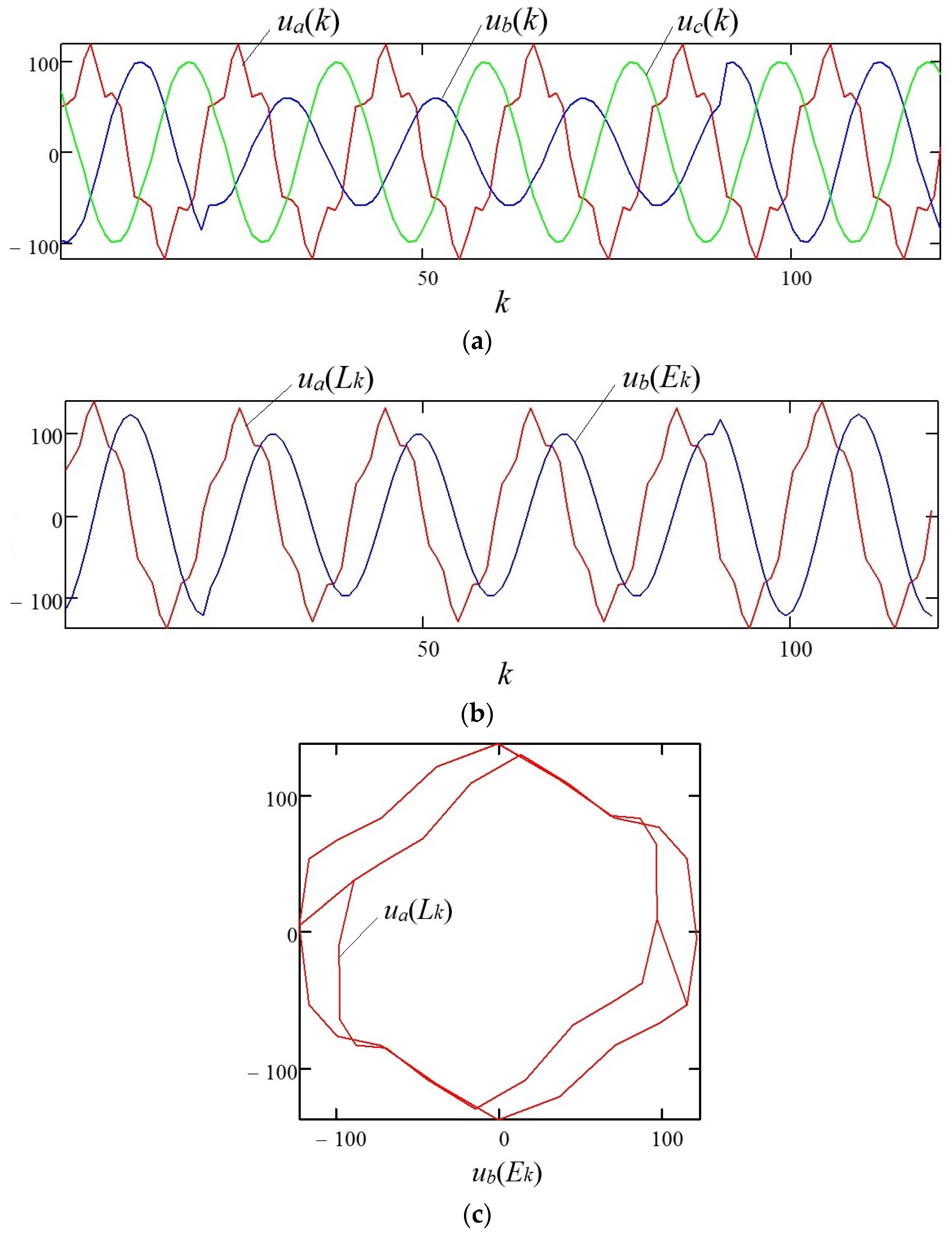
Let a single-phase short circuit (SC) in phase “B” at time t = 20 ms (the 20th sample of the discrete signal in Figure 1) result in the voltage amplitude decrease to 60% of the nominal value in the damaged phase. The distortion of the sinusoidal voltage waveform of a three-phase system is shown in Figure 2a–c.
A distorted three-phase voltage system corresponds to a discrete-time varying change in the values of the coefficient μ (Figure 3), which is calculated using the components of the complex amplitudes of the space vector according to expression (11).
With simultaneous deviations of several PQI from the standard values, the situation with assessing the extent of distortion of the sinusoidal voltage waveform of a three-phase system changes significantly. In phase “A” (Figure 2a), as a result of the influence of a nonlinear single-phase load, let a fifth harmonic additionally appear with an amplitude of 20% of the nominal value of the fundamental harmonic (Figure 4).
Under such conditions, the nature of the dependence of the coefficient μ, which characterizes the extent of distortion of the sinusoidal voltage waveform of a three-phase system, on discrete time k, changes significantly, as shown in Figure 5.
With simultaneous deviations of several PQI from standard values and the complex effect of distortions, the dependence of the coefficient μ on discrete time k becomes unpredictable and random. The randomness of the dependence μ(k) (Figure 5) can lead to errors in estimating the extent of distortion of the sinusoidal voltage waveform of a three-phase system [60,61,62]. Therefore, it is imperative to develop and apply stochastic estimation procedures in automatic PQI control devices [63,64].

4. Results and Discussion

This study proposes the use of multiple-hypothesis statistical testing based on Palmer’s parametric algorithm to solve the problem. To estimate the extent of the sinusoidal voltage waveform distortion, we divide the range of variations in the integral coefficient μ into equal intervals. Let us introduce a classification in which the coefficient μ belongs to the specified interval if, during successive measurements, the hypothesis m (m = 1, …, M) is true, and when the average value (mathematical expectation) μ^ corresponds to the average value of the analyzed interval m.
By way of illustration, Table 1 shows the ranges of variation in the coefficient μ and the average values of μ when estimating the extent of distortion of the sinusoidal voltage waveform of a three-phase system with accuracy of 5%.
Note that the coefficient μ has normalized values lying in the range [0; 1]. It is advisable to determine possible damage for the industrial power supply systems from the sinusoidal voltage waveform distortions for each of the ranges (Table 1).
The sequential assessment of the complex amplitude ratio μ under conditions of measurement errors and random PQI deviations from standard values suggest that the average values of μ^ for each of the m hypotheses will have a normal distribution (Figure 6).
Thus, automatic PQI control with the estimation of the extent of distortion of the sinusoidal voltage waveform of a three-phase system, as well as the damage when PQI deviates from standard values [65,66,67], is reduced to the implementation of multiple-hypothesis sequential statistical testing.
An option for implementing sequential testing for M hypotheses, which does not directly follow from the classical Wald procedure [68], was proposed by Palmer [24]. Similar to the procedure outlined in [69], each step n of the algorithm involves calculation of M likelihood ratios, and then only two of their maximum values are compared.
In this case, the following sequence of actions is implemented under the assumption that μ = x:
  • Calculate M likelihood ratio at each step n of the procedure by Expression (18):
    λ m n = p m n x p 1 n x ,
    where random x is the value regarding which a multiple-hypothesis decision is made; m = 1, 2, …, M; p m n ( x ) and p 1 n ( x ) are probability densities for the random variable x corresponding to hypotheses m and 1; hypothesis m = 1 corresponds to the interval of smallest values of μ and the extent of three-phase voltage distortion not exceeding 5% (Table 1);
  • Determine the two largest of M likelihood ratio values at each step n ( λ m a x 1 n and λ m a x 2 n ), and select hypotheses corresponding to these likelihood ratios;
  • Determine threshold values λ m n for each of the selected hypotheses, using Expression (19):
    λ m n = M 4 · ( 1     P m m ) 2 ,
    where P m m is the probability of correct classification of hypothesis m;
  • Calculate ratio of λ m a x 1 n to λ m a x 2 n and compare it with the threshold value λ m n :
    λ m a x n = λ m a x 1 n λ m a x 2 n   ,
    with threshold λ m n ;
  • Make a decision about the validity of hypothesis m using Expression (20) provided that:
    λ m a x n = λ m a x 1 n λ m a x 2 n λ m n ,
    otherwise, make a decision to continue observations.
The sequential testing procedure continues until the calculated value   λ m a x 1 n / λ m a x 2 n exceeds the threshold value λ m n , which corresponds to the hypothesis with the maximum likelihood ratio.
The developed block diagram of the algorithm for automatic classification of the extent of distortion of the sinusoidal voltage waveform of a three-phase system based on multiple-hypothesis sequential testing according to Palmer’s algorithm is shown in Figure 7.
For the implementation of the algorithm, the assumption is made that there is a set of sample values of the coefficient μ (Table 2) for making a decision during automatic classification of the extent of the three-phase sinusoidal voltage waveform distortion.
Consider an example of implementing the multiple-hypothesis sequential testing procedure with Palmer’s algorithm. In the example, the standard deviations σ of the normal distribution laws (Figure 6) for each of the intervals (Table 2) are assumed to be equal in value and amount to σ = 0.025. The probabilities of correct classification of hypotheses are also deemed to be equal, P m m = 0.75. Therefore, the threshold values λ m n will be equal for each of the m hypotheses given in Table 2 (m = 1, …, 5):
λ m n = M 4 · ( 1     P m m ) 2 = 5 4 · ( 1     0.75 ) 2 = 19.8 .  
The likelihood ratios λ m n for each of the m hypotheses are calculated using the standard Gaussian function according to Expression (22):
f x = 1 2 π · exp x 2 2   .  
the tables of which are given in [70].
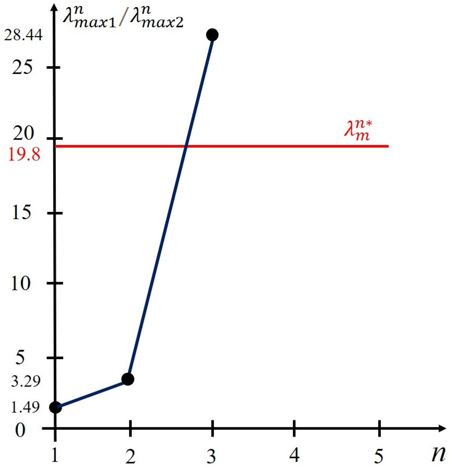
Then, given the values of the coefficient μ (Table 2), we obtain the results at each step n of the sequential testing with Palmer’s algorithm (Figure 8), which are summarized in Table 3.
As seen in Table 3, at the first step of the procedure, the maximum value of the likelihood ratio corresponds to the hypothesis m = 3 (max1 = 3), and the second largest likelihood ratio is the hypothesis m = 2 (max2 = 2).
At the first step, a decision is made to continue observation based on the comparison of statistical data: λ m a x n = λ m a x 1 n λ m a x 2 n = 1.49 with a threshold value λ m n   = 19.8 . At the second step, the maximum likelihood ratio is also characteristic of the hypothesis m = 3 (max1 = 3), while the second largest likelihood ratio is the hypothesis m = 3 (max2 = 2). However, at the second step, the ratio λ m a x n = λ m a x 1 n λ m a x 2 n = 3.29   does not exceed the threshold value λ m n   = 19.8 either.
The final decision to end the observation is made at step n = 3 by accepting hypothesis m = 3, according to which the extent of the sinusoidal voltage distortion waveform corresponds to a 15% variation in the coefficient μ.
An example of the implementation of the multiple-hypothesis sequential testing procedure with Palmer’s algorithm is shown in Figure 8.
Analysis of Figure 8 enables us to draw the following conclusions:
  • The sequential assessment of the extent of the sinusoidal voltage waveform distortion leads to the adoption of the hypothesis of a 15% distortion of the coefficient μ, which corresponds to an unacceptable amount of damage for an industrial consumer;
  • The procedure for multiple-hypothesis sequential testing by Palmer’s algorithm is completed at step 3, which does not require significant time expenditure and has virtually no effect on the performance of the automatic PQI control device;
  • The speed of decision making in multiple-hypothesis sequential testing with Palmer’s algorithm depends on the degree of distortion of the sinusoidal voltage waveform, including PQI deviations from standard values.
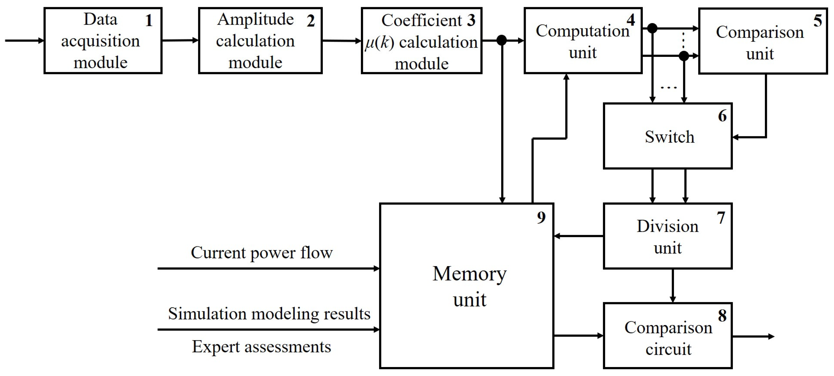
The flowchart of the developed automatic PQI control device, which implements multiple-hypothesis sequential testing with Palmer’s algorithm, is shown in Figure 9. This device automatically assesses the extent of distortion of the sinusoidal voltage waveform of a three-phase system. The automatic PQI control device incorporates a data acquisition module (1); amplitude calculation module (2); coefficient μ calculation module (3); computation unit (4); comparison unit (5); switch (6); division unit (7); comparison circuit (8), and memory unit (9).
Module 1 of the device (Figure 9) is designed to be connected to each phase of a three-phase electrical network in the industrial power supply system in order to measure phase voltage values at the analyzed node. In module 1, analog-to-digital conversion is performed and instantaneous values of all phase voltages are sent to its output.
Module 1 is connected to module 2, which receives instantaneous values of phase voltages ua(k), ub(k), uc(k), measured at the analyzed node. At each time instant, module 2 calculates the phase voltage amplitudes Ua, Ub, Uc. The device (Figure 9) does not calculate the space vector, and the coefficient μ is obtained using Expressions (16) and (17).
Instantaneous amplitudes Ua(k), Ub (k), Uc(k) are calculated from instantaneous values ua(k), ub(k), uc(k), using “short data window” algorithms, in particular, the two-sample test [71].
For example, for the voltage of phase “A”, one can use the relations given in expression (23):
U a k = 1 sin 2 π · f · t d · u a k · e x p j 2 π · f · t d u a k 1 = U a k j U a q k ,
where Ua (k) and Uaq(k) are the quadrature (orthogonal) components of the complex vector U a _ ( k ) .
The validity of Expression (23) can be easily verified by substituting the components:
u a k = U a · s i n ( 2 π · f · k · t d + φ ) , u a k 1 = U a · s i n ( 2 π · f · ( k 1 ) · t d + φ ) ,
which form the complex vector U a _ ( k ) =   U a · e x p j 2 π · f · t d + φ = U a k j U a q k with an initial phase φ (at k = 0) of the amplitude Ua, rotating with angular velocity 2π∙f relative to the origin of coordinates.
The instantaneous amplitude of the voltage vector U a _ ( k ) is calculated by the expression:
U a _ ( k ) = U a _ k = U a k 2 + U a q k 2 ,
It is advisable to use similar formulae to calculate the instantaneous voltage amplitudes of phases “B” and “C”.
Module 3 is designed to calculate the coefficient μ using instantaneous phase voltage amplitudes Ua(k), Ub(k), Uc(k).
Expressions (16) and (17) can be used to obtain the following equality for the instantaneous value of the coefficient μ(k):
μ k = B _ k A * k =   2 4   U b k U c k   2 + 6 12   2 U a k U b k   U c k 2 6 6   2 U a k + U b k + U c k .
Thus, only instantaneous values of the phase voltage amplitudes Ua(k), Ub(k), Uc(k) are used to directly calculate the coefficient μ(k). In this case, it is not necessary to use the Clarke transform. The calculated values of μ(k) from Module 3 arrive at the input of computation unit 4 and memory unit 9.
M likelihood ratios are calculated in computation unit 4 using Expression (18) for a specific discrete value μ(k) by Expression (26):
λ m n = p m n μ k p 1 n μ k ; m = 1 , , M .
In doing so, we use information on probability density distributions (Figure 6) for various hypotheses, which are formed at the preliminary stage based on the results of simulation modeling using statistical information processing or expert assessments. These results are entered into memory unit 9 and go from its output to unit 4 in the form of discrete values μ(k). It is important to emphasize that the range of variations in the value of μ is divided into intervals based on the individual characteristics of various groups of electrical loads of an industrial consumer. This is necessary for the best adaptation of automatic PQI control devices to the magnitude of damage when PQI deviates from standard values.
Comparison unit 5 together with switch 6 select two maximum values of likelihood ratios at each step of sequential testing ( λ m a x 1 n and λ m a x 2 n ) and hypotheses corresponding to these likelihood ratios.
The ratio of λ m a x 1 n to λ m a x 2 n   ( λ m a x n = λ m a x 1 n λ m a x 2 n ) is calculated in division unit 7, and information about the most plausible hypothesis involved in this ratio enters memory unit 9. This information is utilized to choose threshold λ m n = M 4 · ( 1     P m m ) 2 , here m is the maximum plausible hypothesis. The threshold value λ m n is delivered from the output of memory unit 9 to the input of comparison circuit 8, the second input of which receives the calculated value of the ratio λ m a x n = λ m a x 1 n λ m a x 2 n from division unit 7.
If the condition λ m a x n = λ m a x 1 n λ m a x 2 n λ m n is met, then a decision is made about the validity of hypothesis m, and at the output of comparison circuit 8, a signal is generated about the correspondence of the extent of the sinusoidal voltage waveform distortion to the section with coefficient μ, which corresponds to this hypothesis. Otherwise, the automatic classification of the extent of the distortion of the sinusoidal voltage waveform of a three-phase system does not occur, and sequential testing continues.
The degree to which sinusoidal voltage distortions influence the operation of essential electrical loads depends on the composition of the switched-on electrical loads and their characteristics [72]. Therefore, the amount of damage to an industrial consumer, as well as options for organizing automatic control of PQI, should depend on the current operating conditions of the internal power supply system. Therefore, in various conditions, one should choose the appropriate options for dividing the range of changes in the coefficient μ (Figure 6). For example, the range can be divided into heterogeneous sections, and various threshold values λ m n = M 4 · ( 1     P m m ) 2 can be set for different hypotheses by changing the probability P m m , which will influence the results of the sequential testing procedure.
Variability in the results of PQI analysis in the automatic PQI control device (Figure 9) under various operating conditions of the industrial power supply system is achieved by selecting sequential analysis parameters from memory unit 9, depending on the current topological and operating conditions.
Almost all sequential analysis algorithms use statistical relationships in the form of likelihood ratios to make decisions [68]. Statistical data, however, may not be available for automatic PQI control in industrial power supply systems. In this case, a statistical nonparametric approach should be used, for example, based on the nearest neighbor method, which does not require a set of preliminary data for the classification procedure.
One of the widely used nonparametric classification methods, which is called the nearest neighbor method, involves calculating the “distance” between an observed random variable x and a set of its reference values Gm [73]. According to this method, for an L-dimensional random variable xl, hypothesis m (m = 1, 2, …, M) is accepted if the minimum Euclidean distance between xl and Gm,l is ensured based on the expression:
m = argmin l l = 1 L x l G m , l 2 .
The integration of the sequential testing procedure and the nearest neighbor method can be performed using the following algorithm:
  • Calculate the average value of the random variable x at step n of sequential testing:
    x ^ = 1 n i = 1 n x i ;
  • Determine the minimum distance dmin, which for an L-dimensional random variable x ^ can be found by Expression (29):
    d m i n = min l l = 1 L x l ^ G m , l 2 ;
  • Classify the extent of the sinusoidal voltage waveform distortion by comparing it with hypothesis m:
    m = arg min l l = 1 L x l ^ G m , l 2 ,
    and by comparing the value dmin with the threshold Am(n), dminAm(n);
  • Check if the condition dminAm(n) is met, otherwise continue sequential analysis.
The developed block diagram of the algorithm for the automatic classification of the extent of a sinusoidal voltage waveform distortion, which implements multiple-hypothesis sequential testing based on the nearest neighbor method, is shown in Figure 10.
Statistical averaging when implementing a multiple-hypothesis sequential testing algorithm based on the nearest neighbor method (Figure 10) allows for increasing the likelihood of correct decision-making when assessing the extent of the sinusoidal voltage waveform distortion under the influence of random factors.
To select the threshold value Am(n), it is advisable to use the calculation methods employed for parametric algorithms. For example, according to the Armitage algorithm [38], the threshold value is calculated using Expression (30):
A m n = λ m n m , q = 1 P m q · 1 m q P m q .
where m, q = 1, …, M; Pmq is the conditional probability of making a decision about the number of hypothesis m regarding the extent of the sinusoidal voltage waveform distortion, provided that the distortions belong to hypothesis q.
For the algorithm shown in Figure 10, the hypothesis accepted under number q corresponds to distance d, the value of which is the next smallest value after dmin. The number of observations, while maintaining the simplicity of the approach, can be reduced by applying a multiple-hypothesis sequential testing procedure. By analogy with [69], we will establish a set of threshold values that depend on the number of observations n:
A m n = λ m n m , q = λ m n   m , q n ( r ) ,   m , q = 1 , , M ; m   q ,
where λ m n   m , q is the threshold determined by expression (30), and r is a positive constant.
According to [69], the calculations using expression (31) with r = 1 significantly reduce the average number of required observations and have virtually no effect on the classifier error probabilities.
In contrast to similar parametric methods, the multiple-hypothesis sequential testing procedure based on the nearest neighbor method does not require knowledge of the parameters of statistical distributions when implementing computational algorithms.
We will illustrate the implementation of the algorithm (Figure 10) through a calculation example. To do this, we use the initial data given in Table 1 and Table 2. Assume that the classification of distortions of the sinusoidal voltage waveform of a three-phase system is based on the correlation of the average value of coefficient μ^ with the mathematical expectations of statistical distributions (Figure 6). At each step n of the multiple-hypothesis sequential testing procedure based on the nearest neighbor method, we calculate the distance for m intervals (Table 1) and compare the obtained distance values with the corresponding thresholds calculated by Expression (31).
Let us calculate the threshold values using Expression (31) by specifying the probability matrix P to determine the probability of errors and correct decisions when classifying distortions of the sinusoidal voltage waveform of a three-phase system involved in expression (30). For example, given the total number of distortion options M = 5, matrix P is set in the form:
P = 0.75 0.063 0.063 0.063 0.063 0.063 0.75 0.063 0.063 0.063 0.063 0.063 0.75 0.063 0.063 0.063 0.063 0.063 0.75 0.063 0.063 0.063 0.063 0.063 0.75 .
With this specification of the probability matrix P, the threshold values for all options of distortion m (m = 1, …, M) are the same and equal to:
A m n = λ m n = 1 P m q · 1 m q P m q = 1 0.063 · 1 0.25 = 11.9 .
Considering the change in the values of variable μ at issue and the threshold value calculated using the Armitage algorithm (expression (33)), we introduce a normalizing coefficient for μ equal to 300.
The results of intermediate calculations at the stages of multiple-hypothesis sequential testing based on the nearest neighbor method are shown in Table 4.
Analysis of the data in Table 4 suggests that the decision to end observations is made at step n = 3, i.e., the step with the adoption of option m = 3, according to which the extent of distortion of the sinusoidal voltage waveform of a three-phase system corresponds to a 15% change in coefficient μ.
An example of the implementation of the multiple-hypothesis sequential testing procedure based on the nearest neighbor method is shown in Figure 11.
Analysis of Figure 11 and Table 4 indicates that:
  • The sequential assessment of the extent of the sinusoidal voltage waveform distortion based on the nearest neighbor method, as in the case of using Palmer’s algorithm, leads to the acceptance of the hypothesis of a 15% distortion of coefficient μ;
  • The multiple-hypothesis sequential testing procedure is completed at Step 3 (Figure 11), which does not require significant time, therefore, there is no need to introduce an adaptive threshold to increase the speed of the algorithm;
  • The advantage of the multiple-hypothesis sequential testing based on the nearest neighbor method is that there is no need to use statistics and distributions in the calculation process.
The developed flowchart of the automatic PQI control device, which implements sequential testing of multiple hypotheses based on the nearest neighbor method, is shown in Figure 12.
The flowchart of the automatic PQI control device (Figure 12) has a similar but somewhat simplified structure compared to that for the device implementing multiple-hypothesis sequential testing with Palmer’s algorithm (Figure 9). Modules 1–3 of the control PQI device shown in Figure 12 function similarly to the same modules in the automatic PQI control device in Figure 9.
In distance calculation unit 4, distances are calculated using normalized discrete average values of coefficients μ^nor(k) obtained from the results of averaging the values μ(k) received at its input. Averaging is carried out in accordance with Expression (28), and normalization factors in the normalizing coefficient come from memory unit 9. Distances are calculated using Expression (29) as the square of the difference between μ^nor(k) and the normalized values of the range centers (Table 1), which characterize the extent of the sinusoidal voltage waveform distortion.
Next, the minimum of the distances is selected, which involves comparison unit 5 and switch 6. The latter transmits the minimum value of the distances dmin (expression (29)) to the input of comparison circuit 7. The threshold value Am, obtained from expression (30) is received from memory unit 9 at the other input of comparison circuit 7(n). The condition dminAm(n) is checked, and if it is met, the multiple-hypothesis sequential testing procedure ends. If the condition dminAm(n) is not fulfilled, the procedure continues.
Range number (Table 1) corresponding to the minimum distance dmin, for which the condition dminAm(n) is met, characterizes the extent of distortion of the sinusoidal voltage waveform of a three-phase system [74,75].
The methods developed for PQI control in this study enable real-time analysis and decision making for PQI deviations, whereas the PQI analysis carried out following the requirements of effective regulatory documents involves the digital processing of current and voltage signals over long time intervals corresponding to units and tens of seconds [8].
The proposed methods of PQI control can be effective when implemented at digital substations designed according to the IEC 61850 standard requirements, with a sampling rate of 256 samples per cycle of power frequency [76]. The modeling results have shown that a decision on the distortion of sinusoidal voltage waveform is made, on average, in three steps of sequential testing (Figure 8 and Figure 11). This corresponds to the algorithm operating time t = 3∙(20∙10−3/256) = 2.34∙10−4 s at f = 50 Hz.

Future Research Directions

In the first stage, we plan to implement the proposed approaches in the form of automatic PQI control devices and conduct their laboratory tests to confirm the obtained analytical results. The second stage aims to introduce the developed devices for automatic PQI control as part of a pilot project in the power supply system of one of the industrial consumers to collect statistical data on the impact of PQI deviations on the amount of damage. In the third stage, a decision support system will be developed for dispatch personnel of power grid companies and industrial consumers, which will allow them to make operational decisions on the measures to be implemented in external and internal power supply networks to ensure that the PQI values are within the acceptable range.

5. Conclusions

Industrial power supply systems can experience significant deviations in power quality indices from standard values for various reasons. These deviations can result in defective products, the complete shutdown of production processes, and significant damage.
The stochastic nature of PQI deviations justifies the necessity of applying statistical procedures, as well as parametric and nonparametric sequential testing of multiple hypotheses to assess and classify the extent of distortion of the sinusoidal voltage waveform of a three-phase system.
An integrated indicator is proposed to assess the extent of distortion of the sinusoidal voltage waveform of a three-phase system. This indicator is based on the use of the magnitude of the ratio of complex amplitudes of the forward and reverse rotation of the space vector. The integrated indicator can be calculated using weighted values of instantaneous amplitudes of three voltage phases without applying the Clarke transform.
Calculation examples have proven that the developed block diagrams of algorithms and flowcharts of devices for automatic PQI control based on Palmer’s algorithm and the nearest neighbor method, which implement the sequential testing of multiple hypotheses using the integrated indicator, demonstrate high speed and performance when detecting PQI deviations.

Author Contributions

Conceptualization, A.K., P.I. and A.S.; methodology, A.K. and S.F.; software, A.K. and P.I.; validation, A.S., K.S. and S.F.; formal analysis, A.K and A.S.; investigation, A.K., A.S. and K.S.; resources, A.S. and S.F.; data curation, P.I.; writing—original draft preparation, A.K., P.I. and A.S.; writing—review and editing, S.F. and K.S.; visualization, P.I. and K.S.; supervision, A.K.; project administration, P.I and K.S.; funding acquisition, S.F. All authors have read and agreed to the published version of the manuscript.

Funding

This work is supported by the Russian Science Foundation under grant 21-79-30013 in the Energy Research Institute of the Russian Academy of Sciences.

Data Availability Statement

The original contributions presented in the study are included in the article; further inquiries can be directed to the corresponding author/s.

Conflicts of Interest

The authors declare no conflicts of interest. The funders had no role in the design of the study; in the collection, analyses, or interpretation of data; in the writing of the manuscript; or in the decision to publish the results.

References

  1. Luo, F.; Ge, N.; Xu, J. Power Supply Reliability Analysis of Distribution Systems Considering Data Transmission Quality of Distribution Automation Terminals. Energies 2023, 16, 7826. [Google Scholar] [CrossRef]
  2. Petrova, R.; Gracheva, E.; Valtchev, S.; Miftakhova, N. Methods for assessing the reliability of in-shop power supply. Vestn. MSTU 2023, 26, 395–409. [Google Scholar] [CrossRef]
  3. Praiselin, W.J.; Edward, J.B. A review on impacts of power quality, control and optimization strategies of integration of renewable energy based microgrid operation. Int. J. Intell. Syst. Appl. 2018, 10, 67–81. [Google Scholar] [CrossRef]
  4. Kulikov, A.L.; Shepovalova, O.V.; Ilyushin, P.V.; Filippov, S.P.; Chirkov, S.V. Control of electric power quality indicators in distribution networks comprising a high share of solar photovoltaic and wind power stations. Energy Rep. 2022, 8, 1501–1514. [Google Scholar] [CrossRef]
  5. Dong, F.; Qin, C.; Zhang, X.; Zhao, X.; Pan, Y.; Gao, Y.; Zhu, J.; Li, Y. Towards carbon neutrality: The impact of renewable energy development on carbon emission efficiency. Int. J. Environ. Res. Public Health 2021, 18, 13284. [Google Scholar] [CrossRef]
  6. Zhang, H. Technology innovation, economic growth and carbon emissions in the context of carbon neutrality: Evidence from BRICS. Sustainability 2021, 13, 11138. [Google Scholar] [CrossRef]
  7. Wang, C.; Jiang, Y.; Guo, H.; Bai, K.; Zhang, X.; Wang, A. A joint clearing model for the participation of renewable energy and energy storage in the frequency modulation ancillary service market considering performance differences. Front. Energy Res. 2023, 11, 1332041. [Google Scholar] [CrossRef]
  8. Ribeiro, P.F.; Duque, C.A.; Silveira, P.M.; Cerqueira, A.S. Power Systems Signal Processing for Smart Grids; John Wiley & Sons Ltd.: Chichester, UK, 2014. [Google Scholar]
  9. Kuboń, M.; Skibko, Z.; Tabor, S.; Malaga-Toboła, U.; Borusiewicz, A.; Romaniuk, W.; Zarajczyk, J.; Neuberger, P. Analysis of Voltage Distortions in the Power Grid Arising from Agricultural Biogas Plant Operation. Energies 2023, 16, 6189. [Google Scholar] [CrossRef]
  10. Ilyushin, P.; Filippov, S.; Kulikov, A.; Suslov, K.; Karamov, D. Specific Features of Operation of Distributed Generation Facilities Based on Gas Reciprocating Units in Internal Power Systems of Industrial Entities. Machines 2022, 10, 693. [Google Scholar] [CrossRef]
  11. Lesnykh, V.V.; Timofeyeva, T.B.; Petrov, V.S. Problems of the Assessment of Economic Damage Caused by Power Supply Interruption. Econ. Reg. 2017, 13, 847–858. [Google Scholar] [CrossRef]
  12. Ilyushin, P.; Volnyi, V.; Suslov, K.; Filippov, S. Review of Methods for Addressing Challenging Issues in the Operation of Protection Devices in Microgrids with Voltages of up to 1 kV that Integrates Distributed Energy Resources. Energies 2022, 15, 9186. [Google Scholar] [CrossRef]
  13. Ilyushin, P.; Volnyi, V.; Suslov, K.; Filippov, S. State-of-the-Art Literature Review of Power Flow Control Methods for Low-Voltage AC and AC-DC Microgrids. Energies 2023, 16, 3153. [Google Scholar] [CrossRef]
  14. Mishra, S.; Anderson, K.; Miller, B.; Boyer, K.; Warren, A. Microgrid resilience: A holistic approach for assessing threats, identifying vulnerabilities, and designing corresponding mitigation strategies. Appl. Energy 2020, 264, 114726. [Google Scholar] [CrossRef]
  15. Kulikov, A.L.; Ilyushin, P.V.; Suslov, K.V.; Karamov, D.N. Coherence of digital processing of current and voltage signals at decimation for power systems with a large share of renewable power stations. Energy Rep. 2022, 8, 1464–1478. [Google Scholar] [CrossRef]
  16. Kłosowski, Z.; Mazur, Ł. Influence of the Type of Receiver on Electrical Energy Losses in Power Grids. Energies 2023, 16, 5660. [Google Scholar] [CrossRef]
  17. Sinchuk, O.; Strzelecki, R.M.; Beridze, T.; Peresunko, I.; Baranovskyi, V.; Kobeliatskyi, D.; Zapalskyi, V. Model studies to identify input parameters of an algorithm controlling electric supply/consumption process by underground iron ore enterprises. Min. Miner. Depos. 2023, 17, 93–101. [Google Scholar] [CrossRef]
  18. Rakhmonov, I.; Berdishev, A.; Khusanov, B.; Khaliknazarov, U.; Utegenov, U. General characteristics of networks and features of electricity consumers in rural areas. IOP Conf. Ser. Mater. Sci. Eng. 2020, 883, 012104. [Google Scholar] [CrossRef]
  19. 32144-2013; Electrical Energy. Electromagnetic Compatibility of Technical Equipment. Standards for Electric Power Quality in Public Power Supply Systems. Standartinform Publishing: Moscow, Russia, 2014; 15p.
  20. EN 50160; Voltage Characteristics of Electricity Supplied by Public Electricity Networks. CENELEC: Brussels, Belgium, 2010.
  21. Byk, F.; Myshkina, L. Comparison and choice of measures to improve the reliability of distribution grid companies. In Proceedings of the 2nd International Conference on Industrial Engineering, Applications and Manufacturing (ICIEAM), Chelyabinsk, Russia, 19–20 May 2016. [Google Scholar] [CrossRef]
  22. Cao, Y. Study on the interaction of vehicle-to-grid and its impact on power quality of electric grid. J. Phys. Conf. Ser. 2023, 2649, 012007. [Google Scholar] [CrossRef]
  23. Ignatova, V.; Granjon, P.; Bacha, S. Space vector method for voltage dips and swells analysis. IEEE Trans. Power Deliv. 2009, 24, 2054–2061. [Google Scholar] [CrossRef]
  24. Palmer, L.C. Sequential tests to select among M hypotheses. IEEE Trans. Inf. Theory 1972, 18, 211–214. [Google Scholar] [CrossRef]
  25. Basholli, F.; Daberdini, A. Monitoring and assessment of the quality of electricity in a building. Eng. Appl. 2023, 2, 32–48. [Google Scholar]
  26. Zhang, X.J.; Xu, Y.H.; Xiao, X.N. Power quality disturbance detection and identification based on dq conversion and wavelet transform. Electr. Power Autom. Equip. 2005, 25, 1–5. [Google Scholar]
  27. Zhao, F.; Rengang, Y. Power quality disturbance recognition using S-transform. IEEE Trans. Power Deliv. 2007, 22, 944–950. [Google Scholar] [CrossRef]
  28. Balouji, E.; Salor, O. Classification of power quality events using deep learning on event images. In Proceedings of the 3rd International Conference on Pattern Recognition and Image Analysis (IPRIA), Shahrekord, Iran, 19–20 April 2017; pp. 216–221. [Google Scholar] [CrossRef]
  29. Ma, J.; Zhang, J.; Xiao, L.; Chen, K.; Wu, J. Classification of power quality disturbances via deep learning. IETE Tech. Rev. 2016, 34, 408–415. [Google Scholar] [CrossRef]
  30. Sun, L.; Lang, L.; Zhong, W.; Liu, H.; Dong, Y. A Fast Mismatch Calibration Method Based on Frequency Domain Orthogonal Decomposition for Time-Interleaved Analog-to-Digital Converters. Electronics 2023, 12, 5042. [Google Scholar] [CrossRef]
  31. Cong, J. The Use of Wavelet Modulus Maximum Principle in the Detection of Disturbance Signal for Transient Power Quality. Northeast Electr. Power Technol. 2009, 30, 10–13. [Google Scholar]
  32. Chilukuri, M.V.; Dash, P.K. Multiresolution S-transform-based fuzzy recognition system for power quality events. IEEE Tran. Power Deliv. 2004, 19, 323–330. [Google Scholar] [CrossRef]
  33. Ling, L.; Xu, Z. Mathematical Morphology Based Detection and Classification of Dynamic Power Quality Disturbances. Power Syst. Technol. 2006, 30, 62–66. [Google Scholar]
  34. Khoa, N.M.; Dai, L.V. Detection and Classification of Power Quality Disturbances in Power System Using Modified-Combination between the Stockwell Transform and Decision Tree Methods. Energies 2020, 13, 3623. [Google Scholar] [CrossRef]
  35. Lu, G.; Cheng, H.; Zheng, J.; Wang, X. Power Quality Disturbances Detection and Identification Based on S-Transform and Multi-Lay SVMs. Trans. China Electrotech. Soc. 2006, 21, 121–126. [Google Scholar]
  36. Axelberg, P.G.V.; Gu, I.Y.H.; Bollen, M.H.J. Support Vector Machine for classification of voltage disturbances. IEEE Trans. Power Deliv. 2007, 22, 1297–1303. [Google Scholar] [CrossRef]
  37. Ghosh, A.K.; Lubkeman, D.L. The classification of power system disturbance waveforms using a neural network approach. IEEE Trans. Power Deliv. 1990, 10, 671–683. [Google Scholar] [CrossRef]
  38. Zhao, Y.; Xu, Y.; Xiao, X.; Zhu, Y.; Guo, C. Power Quality Disturbances Identification Based on dq Conversion, Wavelet Transform and FFT. In Proceedings of the 2010 Asia-Pacific Power and Energy Engineering Conference, Chengdu, China, 28–31 March 2010. [Google Scholar] [CrossRef]
  39. Kulikov, A.L.; Ilyushin, P.V.; Sevostyanov, A.A. Statistical Sampling for Power-Quality Monitoring in Modern Power-Supply Systems. Russ. Electr. Eng. 2022, 93, 254–260. [Google Scholar] [CrossRef]
  40. Kostadinov, D.; Taskovski, D. Automatic voltage disturbance detection and classification using wavelets and multiclass logistic regression. In Proceedings of the 2012 IEEE International Instrumentation and Measurement Technology Conference (I2MTC), Graz, Austria, 13–16 May 2012; pp. 103–106. [Google Scholar] [CrossRef]
  41. Zhang, M.; Zhan, Y.; He, S. Power Quality Data Compression Based on Iterative PCA Algorithm in Smart Distribution Systems. Smart Grid Renew. Energy 2017, 8, 366–378. [Google Scholar] [CrossRef]
  42. Qu, X.; Dong, K.; Zhao, J.; Yu, Y. An Identification and Location Method for Power Quality Disturbance Sources in MMC Converter Based on KNN Algorithm. In Proceedings of the 4th International Conference on Energy, Electrical and Power Engineering (CEEPE), Chongqing, China, 23–25 April 2021. [Google Scholar] [CrossRef]
  43. Kleijnen, J.P.C.; Shi, W. Sequential probability ratio tests: Conservative and robust. Simulation 2020, 97, 33–43. [Google Scholar] [CrossRef]
  44. Ibrahim, W.R.A.; Morcos, M.M. Artificial intelligence and advanced mathematical tools for power quality applications: A survey. IEEE Power Eng. Rev. 2002, 21, 11. [Google Scholar] [CrossRef]
  45. Granados-Lieberman, D.; Romero-Troncoso, R.J.; Osornio-Rios, R.A.; Garcia-Perez, A.; Cabal-Yepez, E. Techniques and methodologies for power quality analysis and disturbances classification in power systems: A review. IET Gener. Transm. Distrib. 2011, 5, 519–529. [Google Scholar] [CrossRef]
  46. Zhao, L.C.; Zou, H.X.; Wei, K.X.; Zhou, S.X.; Meng, G.; Zhang, W.M. Mechanical Intelligent Energy Harvesting: From Methodology to Applications. Adv. Energy Mater. 2023, 13, 2300557. [Google Scholar] [CrossRef]
  47. Zhao, L.C.; Zou, H.X.; Zhao, Y.J.; Wu, Z.Y.; Liu, F.R.; Wei, K.X.; Zhang, W.M. Hybrid energy harvesting for self-powered rotor condition monitoring using maximal utilization strategy in structural space and operation process. Appl. Energy 2022, 314, 118983. [Google Scholar] [CrossRef]
  48. Akhtar, S.; Adeel, M.; Iqbal, M.; Namoun, A.; Tufail, A.; Kim, K.H. Deep learning methods utilization in electric power systems. Energy Rep. 2023, 10, 2138–2151. [Google Scholar] [CrossRef]
  49. Ibrahim, B.; Rabelo, L.; Sarmiento, A.T.; Gutierrez-Franco, E. A Holistic Approach to Power Systems Using Innovative Machine Learning and System Dynamics. Energies 2023, 16, 5225. [Google Scholar] [CrossRef]
  50. Ilyushin, P.V.; Filippov, S.P. Under-frequency load shedding strategies for power districts with distributed generation. In Proceedings of the 2019 International Conference on Industrial Engineering, Applications and Manufacturing (ICIEAM), Sochi, Russia, 25–29 March 2019. [Google Scholar] [CrossRef]
  51. Volodina, O.V.; Skvortsov, A.A.; Nikolaev, V.K. Memory computing based on thermal memory elements. E3S Web of Conf. 2023, 458, 01009. [Google Scholar] [CrossRef]
  52. Ilyushin, P.V.; Shepovalova, O.V.; Filippov, S.P.; Nekrasov, A.A. The effect of complex load on the reliable operation of solar photovoltaic and wind power stations integrated into energy systems and into off-grid energy areas. Energy Rep. 2022, 8, 1515–1529. [Google Scholar] [CrossRef]
  53. Ilyushin, P.; Filippov, S.; Kulikov, A.; Suslov, K.; Karamov, D. Intelligent Control of the Energy Storage System for Reliable Operation of Gas-Fired Reciprocating Engine Plants in Systems of Power Supply to Industrial Facilities. Energies 2022, 15, 6333. [Google Scholar] [CrossRef]
  54. Shamarova, N.; Suslov, K.; Ilyushin, P.; Shushpanov, I. Review of Battery Energy Storage Systems Modeling in Microgrids with Renewables Considering Battery Degradation. Energies 2022, 15, 6967. [Google Scholar] [CrossRef]
  55. Vinogradov, A.; Bolshev, V.; Vinogradova, A.; Jasi´nski, M.; Sikorski, T.; Leonowicz, Z.; Goňo, R.; Jasińska, E. Analysis of the Power Supply Restoration Time after Failures in Power Transmission Lines. Energies 2020, 13, 2736. [Google Scholar] [CrossRef]
  56. Liu, H.; Tang, Y.; Feng, Y.; Ma, X. A Power Quality Disturbance Classification Method Based on Park Transform and Clarke Transform Analysis. In Proceedings of the 3rd International Conference on Innovative Computing Information and Control, Dalian, China, 18–20 June 2008. [Google Scholar] [CrossRef]
  57. Wang, Y.; Bagheri, A.; Bollen, M.H.J.; Xiao, X. Single-event characteristics for voltage dips in three-phase systems. IEEE Trans. Power Deliv. 2017, 32, 832–840. [Google Scholar] [CrossRef]
  58. Xia, Y.; Mandic, D.P. Widely linear adaptive frequency estimation of unbalanced three-phase power systems. IEEE Trans. Instrum. Meas. 2012, 61, 74–83. [Google Scholar] [CrossRef]
  59. Xia, Y.; Wang, K.; Pei, W.; Mandic, D.P. A balancing voltage transformation for robust frequency estimation in unbalanced power systems. In Proceedings of the Signal and Information Processing Association Annual Summit and Conference (APSIPA), Siem Reap, Cambodia, 9–12 December 2014. [Google Scholar] [CrossRef]
  60. Bagheri, A.; Gu, I.Y.H.; Bollen, M.H.J.; Balouji, E. A Robust Transform-Domain Deep Convolutional Network for Voltage Dip Classification. IEEE Trans. Power Deliv. 2018, 33, 2794–2802. [Google Scholar] [CrossRef]
  61. Bagheri, A.; Bollen, M.H.J.; Gu, I.Y.H. Improved characterization of multistage voltage dips based on the space phasor model. Electr. Power Syst. Res. 2018, 154, 319–328. [Google Scholar] [CrossRef]
  62. Rönnberg, S.K.; Bollen, M.H.J. Power quality issues in the electric power system of the future. Electr. J. 2016, 29, 49–61. [Google Scholar] [CrossRef]
  63. Papkov, B.; Gerhards, J.; Mahnitko, A. System problems of power supply reliability analysis formalization. In Proceedings of the IEEE 5th International Conference on Power Engineering, Energy and Electrical Drives, Riga, Latvia, 11–13 May 2015; pp. 225–228. [Google Scholar] [CrossRef]
  64. Huang, J.S.; Negnevitsky, M.; Nguyen, D.T. A Neural-Fuzzy Classifier for Recognition of Power Quality Disturbances. IEEE Trans. Power Deliv. 2002, 17, 609–616. [Google Scholar] [CrossRef]
  65. Leprette, B.; Craciun, O.; Basha, S.; Granjon, P.; Radu, D. Method and Device of the Electric Power Quality Analysis in a Three-Phase Electric Network. Russian Federation Patent No. RU 2613584, 17 March 2017. [Google Scholar]
  66. Burmeyster, M.V.; Bulatov, R.V.; Nasyrov, R.R.; Aljendy, R.; Dominguez, O.F. Study and analysis of the influence of wind power station on the power quality. In Proceedings of the 2nd International Youth Conference on Radio Electronics, Electrical and Power Engineering (REEPE), Moscow, Russia, 12–14 March 2020; p. 9059105. [Google Scholar] [CrossRef]
  67. Styvaktakis, E.; Bollen, M.H.J.; Gu, I.Y.H. Expert system for classification and analysis of power system events. IEEE Trans. Power Deliv. 2002, 17, 423–428. [Google Scholar] [CrossRef]
  68. Wald, A. Sequential Analysis; John Wiley and Sons: New York, NY, USA, 1947. [Google Scholar]
  69. Jouny, I.; Garber, F.D. M-ary sequential hypothesis tests for automatic target recognition. IEEE Trans. Aerosp. Electron. Syst. 1992, 28, 473–483. [Google Scholar] [CrossRef]
  70. Wenzel, E.S. Probability Theory: Textbook for Universities, 7th ed.; Vysshaya Shkola: Moscow, Russia, 2001; 575p. [Google Scholar]
  71. Shneerson, E.M. Digital Relay Protection; Energoatomizdat: Moscow, Russia, 2007; 548p. [Google Scholar]
  72. Ilyushin, P.V.; Pazderin, A.V. Requirements for power stations islanding automation an influence of power grid parameters and loads. In Proceedings of the 2018 International Conference on Industrial Engineering, Applications and Manufacturing (ICIEAM), Moscow, Russia, 15–18 May 2018. [Google Scholar]
  73. Kislitsyn, A.A.; Kislitsyna, M.Y. Recognition of sample distributions among a system of standards: The nearest neighbor method. Keldysh Inst. Prepr. 2023, 29, 21. [Google Scholar] [CrossRef]
  74. Sun, H.; Li, F.; Sticht, C.; Mukherjee, S. Circular Trajectory Approach for Online Sinusoidal Signal Distortion Monitoring and Visualization. IEEE Trans. Smart Grid 2022, 13, 3315–3318. [Google Scholar] [CrossRef]
  75. Callegari, J.M.S.; Heverton, A.P.; Danilo, I.B. Voltage Support and Selective Harmonic Current Compensation in Advanced AC Microgrids. IEEE Trans. Ind. Appl. 2023, 59, 4880–4892. [Google Scholar] [CrossRef]
  76. IEC 61850; Communication Networks and Systems in Substations. IEC: Geneva, Switzerland, 2004. Available online: http://domino.iec.ch/webstore/webstore.nsf/searchview/?SearchView=&SearchOrder=4&SearchWV=TRUE&SearchMax=1000&Query=61850&submit=OK (accessed on 3 January 2024).
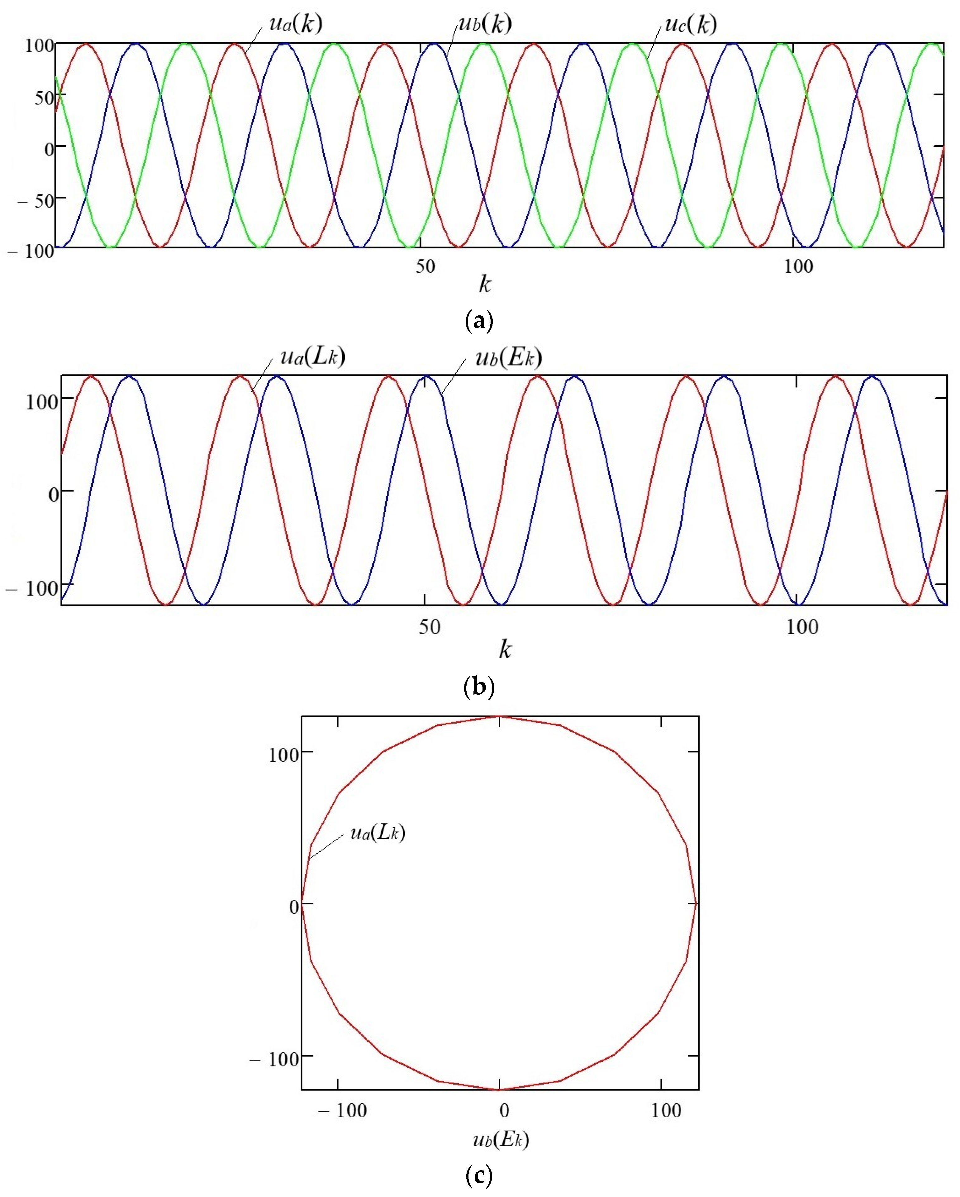
Figure 1. Three-phase symmetrical system of discrete voltages: (a) phase voltages ua(n), ub(n), uc(n) of a three-phase system with power frequency f = 50 Hz; (b) components of the complex space vector; (c) space vector rotation trajectory on the complex plane.
Energies 17 01088 g001
Figure 2. Distortion of the sinusoidal voltage waveform: (a) phase voltage of a three-phase system with a single-phase short circuit in phase “B”; (b) components of the complex space vector; (c) the space vector rotation trajectory on the complex plane.
Energies 17 01088 g002
Figure 3. Time-varying change in the coefficient μ, which characterizes the extent of the sinusoidal voltage waveform distortion.
Energies 17 01088 g003
Figure 4. Distorted three-phase system of discrete voltages with simultaneous deviation of several PQI: (a) phase voltages of a three-phase system with a single-phase short circuit in phase “B” and a nonlinear single-phase load in phase “A”; (b) components of the complex space vector; (c) the space vector rotation trajectory on the complex plane.
Energies 17 01088 g004
Figure 5. Time-varying change in the coefficient μ: (a) with a single-phase short circuit in phase “B” and distortion by the fifth harmonic in phase “A”; (b) with a voltage dip and distortion by the fifth harmonic in all three phases.
Energies 17 01088 g005
Figure 6. An example of probability densities for average values of μ^ corresponding to hypotheses about the extent of sinusoidal voltage waveform distortion.
Energies 17 01088 g006
Figure 7. Block diagram of the algorithm that implements the procedure of multiple-hypothesis sequential testing based on Palmer’s algorithm.
Energies 17 01088 g007
Figure 8. Implementation of the multiple-hypothesis sequential testing procedure according to Palmer’s algorithm.
Energies 17 01088 g008
Figure 9. Flowchart of a device that implements the procedure of multiple-hypothesis sequential testing with Palmer’s algorithm.
Energies 17 01088 g009
Figure 10. Block diagram of an algorithm for the procedure of multiple-hypothesis sequential testing based on the nearest neighbor method.
Energies 17 01088 g010
Figure 11. Implementation of the multiple-hypothesis sequential testing procedure based on the nearest neighbor method.
Energies 17 01088 g011
Figure 12. Flowchart of an automatic PQI control device, which implements multiple-hypothesis sequential testing based on the nearest neighbor method.
Energies 17 01088 g012
Table 1. Variation ranges for the integral coefficient μ.
Variation Ranges of μ0.00–0.05
m = 1
0.05–0.10
m = 2
0.10–0.15
m = 3
0.15–0.20
m = 4
0.20–0.25
m = 5
Average value μ^0.0250.0750.1250.1750.225
Table 2. Sample values of the coefficient μ when classifying the extent of distortion of the sinusoidal voltage waveform of a three-phase system.
Sequential Testing
Procedure Step
n = 1n = 2n = 3n = 4n = 5n = 6n = 7n = 8
Coefficient value μ0.1050.110.1270.1180.120.100.100.124
Table 3. Calculated values of the multiple-hypothesis sequential testing procedure using Palmer’s algorithm.
Procedure Stepn = 1n = 2n = 3n = 4n = 5n = 6
Value   λ m a x 1 n 12.0733266,068
Value   λ m a x 2 n 8.11012323
Ratio   λ m a x 1 n / λ m a x 2 n 1.493.2928.44
Threshold   value   λ m n 19.819.819.819.819.819.8
Accepted
hypothesis m
m = 3
Table 4. The calculated values of the multiple-hypothesis sequential testing procedure based on the nearest neighbor method.
Procedure Stepn = 1n = 2n = 3n = 4n = 5n = 6
Coefficient μnor31.53338.1...
The value of μ^nor31.532.2534.2...
Distance value for distortion option m576
(m = 1)
81
(m = 2)
36
(m = 3)
441
(m = 4)
1296
(m = 5)
625
(m = 1)
100
(m = 2)
25
(m = 3)
410
(m = 4)
1242.6
(m = 5)
712.9
m = 1)
136.9
(m = 2)
10.89
(m = 3)
334.9
(m = 4)
1108.9
(m = 5)
...
Threshold   value   λ m n 11.911.911.911.911.911.9...
Disclaimer/Publisher’s Note: The statements, opinions and data contained in all publications are solely those of the individual author(s) and contributor(s) and not of MDPI and/or the editor(s). MDPI and/or the editor(s) disclaim responsibility for any injury to people or property resulting from any ideas, methods, instructions or products referred to in the content.