Article

A Study on the Transient Response of Compressed Air Energy Storage in the Interaction between Gas Storage Chambers and Horseshoe-Shaped Tunnels in an Abandoned Coal Mine

1
State Key Laboratory of Intelligent Construction and Healthy Operation and Maintenance of Deep Underground Engineering, China University of Mining and Technology, Xuzhou 221116, China
2
Yunlong Lake Laboratory of Deep Underground Science and Engineering, Xuzhou 221116, China
3
Shanghai Urban Construction Municipal Engineering (Group) Co., Ltd., Shanghai 200065, China
4
School of Mechanics and Civil Engineering, China University of Mining and Technology, Xuzhou 221116, China
5
Shanghai Tunnel Engineering Co., Ltd., Shanghai 200032, China
6
China Coal (Tianjin) Underground Engineering Intelligence Research Institute Co., Ltd., Tianjin 300121, China
*
Author to whom correspondence should be addressed.
Energies 2024, 17(4), 953; https://doi.org/10.3390/en17040953
Submission received: 23 January 2024 / Revised: 14 February 2024 / Accepted: 16 February 2024 / Published: 19 February 2024
(This article belongs to the Section D: Energy Storage and Application)

Abstract

:
This study focuses on the renovation and construction of compressed air energy storage chambers within abandoned coal mine roadways. The transient mechanical responses of underground gas storage chambers under a cycle are analyzed through thermal-solid coupling simulations. These simulations highlight changes in key parameters such as displacement, stress, and temperature within the chamber group during the loading and unloading processes of compressed air energy storage. It is found that within a cycle, the small circular chamber experiences the most significant deformation, with an average peak displacement of 0.24 mm, followed by the large circular chamber and horseshoe-shaped tunnels. The small circular chamber exhibits maximum tensile and compressive stresses. Therefore, special attention in engineering practice should be paid to the long-term safety and stability of small circular tunnels, and the stability of horseshoe-shaped tunnels should be also carefully considered. The findings from this study offer some insights for theoretical support and practical implementation in the planning, design, construction, and operation of high-pressure underground gas storage chambers for compressed air energy storage.

1. Introduction

With the continuous growth of global energy demand and concerns about climate change, the development and utilization of renewable energy have become key strategys for global energy transformation [1]. Renewable energy sources, such as wind energy [2], solar energy [3], and geothermal energy [4,5,6], are gradually occupying important positions in energy supply due to their clean and sustainable characteristics. However, these renewable energy sources have unpredictable, intermittent, and fluctuation characteristics [7], which pose great challenges to the stable operation of the power system. During this period, although numerous energy extraction strategies and methods have emerged, such as unconventional shale gas extraction [8,9], coalbed gas–three gas coproduction [10,11,12], carbon dioxide geological storage [13], and salt cavern energy storage [14,15], China still mainly relies on traditional energy sources such as coal [16]. However, due to the relatively limited acceptance capacity of the power system for large-scale renewable energy, a large amount of renewable energy has not been fully integrated into the power grid for supply [17]. This does not only affect the economic viability of renewable energy, but also hinders the pace of China’s transformation towards carbon neutrality and clean energy [18]. In order to address the impact of renewable energy volatility and intermittency on the power grid, large-scale energy storage systems have emerged. These energy storage systems can store energy when renewable energy is plentiful and release energy at times of peak power demand. This approach improves the receiving and regulating capacity of the grid. Among various energy storage technologies, compressed air energy storage [19,20,21] has become one of the energy storage solutions that have attracted much attention due to its advantages, such as a large energy storage capacity, a long storage period, and high efficiency.
Recently, two commercial large compressed air energy storage (CAES) power plants have been put into operation worldwide. In 1978, Huntorf [22], Germany, built the world’s first unit with a power of 290 MW (later upgraded to 321 MW) and an operating efficiency of 29%. In 1991, Mclntosh [23] in Alabama, USA also put into operation a 110 MW unit with an operating efficiency of 54%. These two projects use salt rock chambers for solution mining to store compressed air [24]. The salt karst cavity of the Huntorf power plant was later expanded into a 0.003 km3 natural gas chamber. So far, the power plant has been started more than 7000 times and operates steadily and reliably every day [25]. The Mclntosh power plant can continuously generate electricity for 26 h and is currently the largest CAES power generation system chamber (with a volume of 0.00532 km3), with a pressure range of 4.5–7.4 MPa [26]. In Norton, OH, USA, a plan is being developed to transform an abandoned limestone mine into a compressed air energy storage chamber with a capacity of 2700 MW and an operation pressure of 5.5–11.0 MPa [27]. The Pacific Gas and Electric Company (PG&E) plans to build a 300 MW compressed air energy storage power plant in San Joaquin County, California, with chambers buried at depths of 1425–1463 m [28].
In China, the Institute of Engineering Physics in the Chinese Academy of Sciences completed the first international 1.5 MW demonstration project system in 2013, realizing industrialization [29], and the first 10 MW R&D platform system in the world was built in 2016 [30]. In September 2017, the National Development and Reform Commission and the National Energy Administration issued the Guiding Opinions on Promoting the Development of Energy Storage Technology and Industry, proposing to carry out research and demonstration of 10 MW/100 MW·h level supercritical compressed air energy storage systems. As mentioned in June 2019, according to the “Implementation of the Guiding Opinions on Promoting the Development of Energy Storage Technology and Industry” 2019–2022 Action Plan, China will promote major advanced technology projects, such as large-capacity compressed air energy storage, and, at the same time, promote 100 MW level compressed air energy storage projects. Regarding the practice of using abandoned coal mines for gas storage, in 2019, the Yungang coal mine in Shanxi Province started constructing the first compressed air energy storage power station in China by using abandoned coal mine chambers. The geological structure of the coal mine is stable, and the total length of the roadway is about 9000 m. The project plans to use a length of about 7000 m and a volume of about 90,000 m3. The initial scale is about 60 MW, and the final total scale reaches 100 MW [31]. In 2020, the main project of China’s “Jintan Salt Cave Compressed Air Energy Storage National Experimental Demonstration Project” started construction in Jintan District [32], Changzhou City, and was successfully connected to the grid for power generation in September 2021. This project is the world’s first large-scale non-supplementary combustion compressed air energy storage power station. The first phase of the project has an installed power generation capacity of 60 MW and an energy storage capacity of 300 MW·h. The long-term plan for the project is to reach a capacity of 1000 MW, which will become a large-scale clean physical energy storage base in China, contributing to the early achievement of China’s goals of carbon peak and carbon neutrality.
The underground spaces of abandoned coal mines, as potential gas storage sites, have attracted great interest from researchers due to their rich underground space resources and geological conditions. The underground spaces of abandoned coal mines usually include mining chambers, coal seams, mine shafts, and other structures, which provide natural storage space for gas storage [33]. During the operation of the energy storage system, especially during the process of cyclic charging and discharging, the frequent and rapid circulation of compressed air will cause complex mechanical responses to the surrounding rock and structure of the abandoned coal mine’s horseshoe-shaped roadway. This involves the interaction of multiple physical fields, such as geomechanics and thermodynamics, which puts higher requirements on key issues such as the stability and sealing of gas storage chambers [21].
During the use of compressed air energy storage devices, the chamber continuously inflates and deflates and operates continuously for 365 days a year, with a lifespan of about 40 years and a total number of cycles close to 20,000. The main performance requirements of the chamber include the sealing performance, stability of the surrounding rock of the chamber, and surface deformation [20]. The volume, geometric shape, operating pressure, burial depth, groundwater level, surrounding rock permeability, and strength of the chamber all affect the requirements of geomechanics [34]. Increasing the chamber pressure by 1 MPa may lead to a temperature increase of 13 °C [35]. When inflating, the pressure inside the chamber increases and the temperature rises; evacuation produces the opposite effect. The surrounding rock is mainly affected by the pressure load caused by periodic temperature and the periodic compression and release of air inside the chamber. Jiang et al. [36] conducted numerical simulations on granite chambers and analyzed their stress characteristics under dynamic loads. In subsequent studies, Wan et al. [37] analyzed a sealing layer of the chamber and studied the effects of different sealing layer materials on stress characteristics. Damjanac et al. [38] analyzed the crack evolution, especially tensile stress, and fatigue caused by periodic loading. Perazzelli et al. [34] analyzed the uplift failure in shallow CAES chambers and the effect of groundwater by using a continuous rock mass model. Kim et al. [39] conducted a preliminary study on the geomechanical effects of excavation damage zones on compressed air energy storage in lined rock chambers and discussed the concept of shallow lined rock chambers as energy storage rock chambers. These research results show that the excavation of underground spaces may result in several excavation damage zones, including irreversible damage zones and excavation disturbance zones [40]. Chen et al. [20] also studied the effect of the compressed air energy storage process on the excavation damage zone using the method of zoning the excavation damage zone.
The previous research conclusion shows that the stability of the energy storage chamber is not as affected by the excavation damage zone as the geometric parameters are, but it is still an important factor to consider. The research on CAES energy storage analysis schemes for chamber clusters is still in its early stage, and the mutual influence of chamber clusters is still unclear. Therefore, this article will delve into the transient mechanical responses of CAES in the underground spaces in abandoned coal mines, especially the mechanical responses of abandoned mines to the surrounding rock and structure of horseshoe-shaped tunnels under the simultaneous operation of double chambers after renovation. The outer boundary conditions only consider the influence between the horseshoe-shaped roadway and gas storage, and the stress action at the far end mainly manifests as in situ stress.

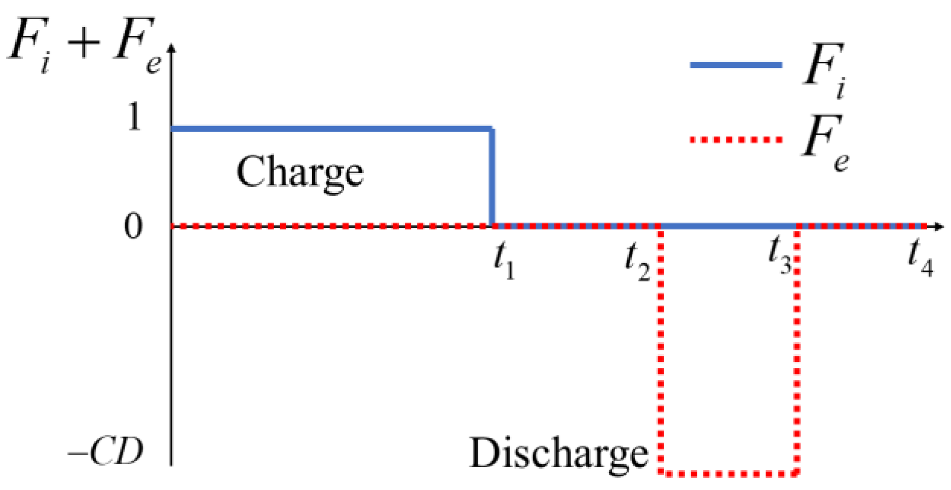
2. Dynamics of Production Injection Cycle and Thermo-Solid Coupling Theory

Kushnir et al. [41] derived numerical and approximate analytical solutions for the changes in temperature and pressure in gas cavity based on the mass conservation equation, energy conservation equation, and gas state equation. Although the non-uniformity of the gas temperature and pressure distribution inside the chamber was ignored in this process, the final calculation accuracy met the requirements for engineering practice. The mass equation mainly characterizes the changes in air density inside the chamber during continuous inflation and deflation. The energy conservation equation takes into account the changes in temperature inside the chamber caused by the interaction between internal and external conditions. The conservation of mass, according to Kushnir et al. [41], is expressed as follows:
V d ρ d t = ( F i + F e ) m i e
where ρ is the density of gas in the chamber, V is the volume of the chamber, and (Fi + Fe)mie is the rate of the mass flow, while mie is the mass flow rate of gas. Figure 1 shows the cyclic changes of CAES during periodic operation. CD refers to the mass flow rate ratio between deflation and inflation, and ml is the gas leakage rate of the surrounding rock of the chamber.
The conservation of energy is expressed as follows [20]:
V ρ c ν d T c d t = F i m i e ( h i h + Z R c T c ρ u ρ | T c ) + ( F e m i e + m l ) ( Z R c T c ρ u ρ | T c ) + Q
where Pc is the chamber pressure, Tc is the temperature of the chamber, Rc is the constant value (Rc = 0.287 × 10³ (J/kg/K)), cv is the volumetric specific heat coefficient, and Z is the compression coefficient of air. h and u are enthalpy and specific heat energy, respectively, Q represents the heat transfer rate.
The gas state equation is as follows:
P c = Z ρ R c T c
The thermodynamic properties of the gas are given by the following equation [41]:
Z Z 0 ,   c ν c ν 0 ,   h i h c p 0 ( T i T c ) ,   ρ u ρ | T c R c T 0 2 Z T 0 ρ 0
where Ti is the gas temperature during the gas charge, and ZT is the derivative of Z over T. Z0, cv0, cp0, and ZT0 are their respective initial states (ρ0, T0): cv0 = 0.718 × 10³ (J/(kg·K)), cp0 = 1.005 × 10³ (J/(kg·K)), Z = 1, and ZT0 = 0.
At the boundary of the chamber, convection and heat conduction occur during the entire period. Therefore, the total heat exchange can be also obtained through integration:
Q = ( T t T c ) A c   h c d A c
where hc and Ac are the heat transfer coefficient and the surface area of the chamber, respectively. Tt is the surface temperature of the surrounding rock of the chamber, and Tc represents the real-time temperature of the chamber.
The strain of non-isothermal surrounding rock mass εij is [42]:
ε i j = 1 2 G σ i j ( 1 6 G 1 9 K ) σ k k δ i j + 1 3 α T Δ T δ i j
where G is the shear modulus and G = E/2(1 + v), E, and v are the Young’s modulus of the rock and the Poisson’s ratio, respectively. αT is the volume expansion coefficient, and ΔT = TT0 is the relative temperature compared to the initial temperature T0.
The Hooke’s law mentioned above is expressed as stress as follows [20]:
σ i j = 2 G ε i j + 2 G ν 1 2 ν ε k k δ i j K α T Δ T δ i j
The expression for volumetric strain is
ε v = ε 1 + ε 2 + ε 3
The expression for volumetric strain can be obtained by combining Equations (6)–(8) as follows:
ε v = σ ¯ K + α T Δ T
where σ ¯ = σ k k / 3 is the average stress. Therefore, the revised force balance equation is
G u i , j j + G 1 2 ν u j , j i K α T Δ T , i + f i = 0
where ui is the displacement in the i direction, and fi is the unit volume force in the i direction. Equation (10) is a tensor expression of the stress equilibrium, with boundary conditions at the far end; the external force fi is equal to the in situ stress, and at the inner boundary of the gas storage, it is equal to the gas pressure. The calculation of the gas pressure is obtained through thermodynamic Equations (1)–(5).

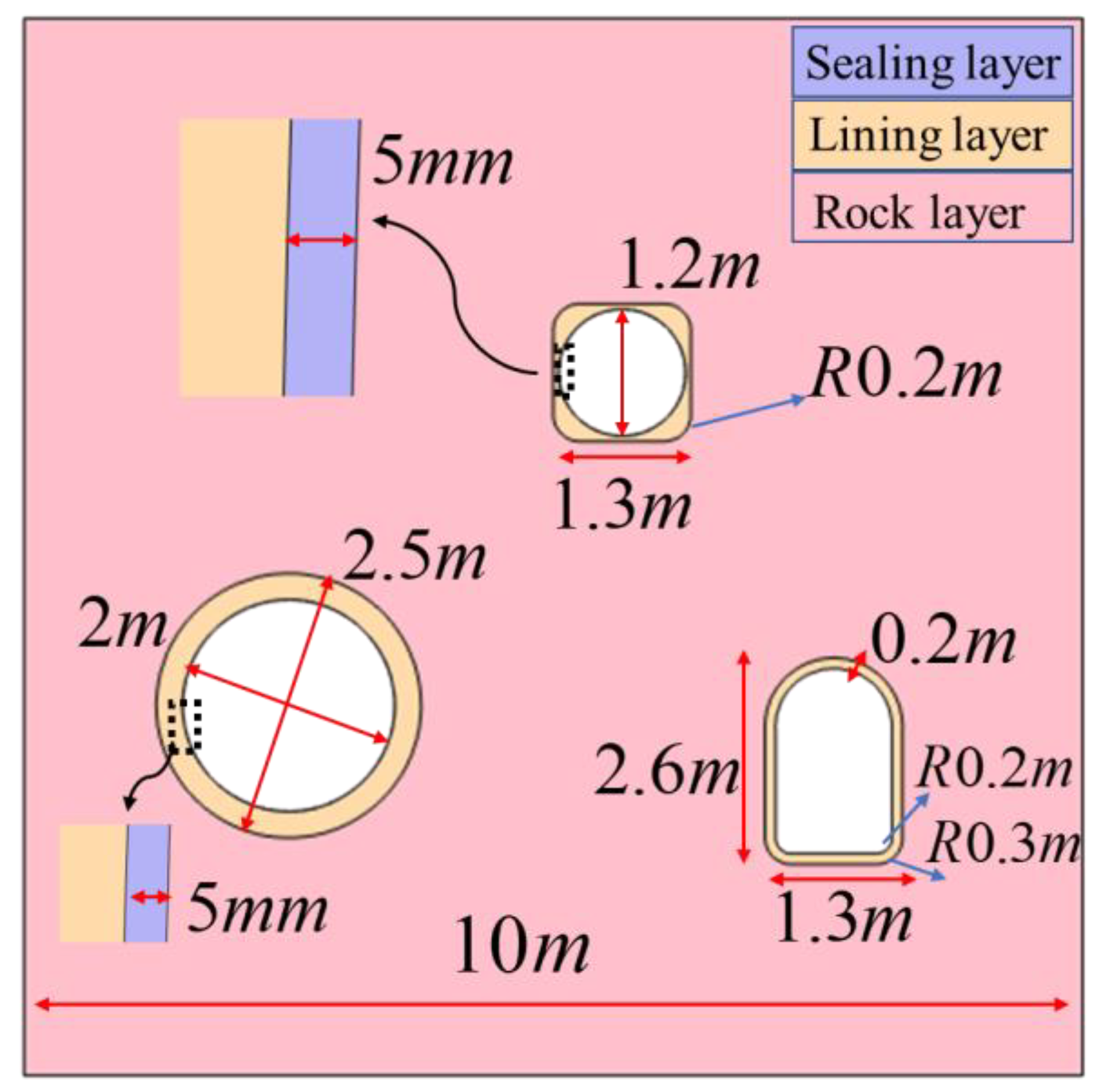
3. Establishment and Verification of a Model for a Group of Compressed Air Energy Storage Chambers in Abandoned Coal Mines

This paper mainly focuses on the preliminary analysis of an abandoned coal mine in Shandong Province. For the compressed air energy storage model, an iterative calculation and analysis are currently required in COMSOL. It is noted that the model needs to be validated and explained before calculation. When this model was established, it simulated the expansion of a circular chamber into a large circular chamber and the backfilling of a square chamber into a small circular chamber as one of the compressed air energy storage chambers. There is a horseshoe-shaped roadway near the renovated circular chamber group, which is only reinforced with concrete and does not consider other factors. According to the research results of Sun et al. [8], the gas pressure influence range of the three-layer chamber is only a dozen meters, but not more than twenty meters. Therefore, in order to save computational power, the calculation domain of the numerical model is 20 × 20 m, and the analysis domain is 10 × 10 m. The chamber model is shown in Figure 2.
In a circular energy storage chamber, the innermost layer is a sealing layer (steel lining), mainly used to prevent gas leakage and stress transfer. The second layer is a concrete layer, which is poured on the basis of excavation or backfilling. Its strength is high, and it contacts the surrounding rock. The third layer is the surrounding rock. For horseshoe-shaped tunnels, the innermost layer is concrete and the outermost layer is surrounding rock. In order to be closer to the actual site during the treatment process, chamfering is used to weaken the unreasonable large stress caused by stress concentration effects. For the construction plan of an abandoned coal mine in Shandong Province, the distribution of elastic modulus is shown in Figure 3. It is noted that Figure 3 does not display the elastic modulus of the sealing layer for convenience during processing. The non-uniformity of the elastic modulus of rocks and concrete is described using Weibull distribution functions. Moreover, Chen et al. [20] verified the feasibility by using Weibull functions in the application of compressed air energy storage in the surrounding rocks of coal mines. The elastic modulus E obeys the three-parameter Weibull distribution, so its probability density function is
f ( E ) = β w α w ( E μ w α w ) β w 1 e ( E μ w α w ) β w
The distribution function is
F ( E ) = 1 e ( E μ w α w ) β w
where βw is the shape parameter, αw is the scale parameter, and μw is the position parameter. This paper takes 2.41, 1.073, and 0.296, respectively.
At present, the construction site of CAES is tentatively located at the second level in the abandoned coal mine. The second horizontal position is developed using two hidden inclined shafts, namely the second horizontal track’s hidden inclined shaft and the tape’s hidden inclined shaft. The track’s hidden inclined shaft is responsible for auxiliary transportation and air intake tasks, while the tape’s hidden inclined shaft is responsible for main transportation and return air tasks. The second-level underground inclined shaft falls in the −180 m horizontal direction, and the mining area is divided into 12 coal seams for mining. Currently, only the 12th coal mining area’s roadway is formed at the second-level position, including the 12th coal mining area’s east wing track roadway, the 12th coal mining area’s east wing belt roadway, the 12th coal mining area’s track roadway, and the 12th coal mining area’s belt roadway. The track roadway and belt roadway in the east wing of the first mining area of the 12th coal seam are arranged along the roof of the coal seam. The roof is mainly composed of mudstone, which has a thickness of 1.54–10.8 m and an average of 3.96 m, and sandy mudstone, which has a thickness of 5.99–22.1 m and an average of 12.9 m. The roof cracks are developed and brittle, and it rises with mining, making it an unstable to moderately stable roof. The track roadway and belt roadway in the second mining area of the 12th coal seam are basically arranged along the coal seam floor. The floor is mainly composed of limestone (eight ash), which has a thickness of 0–2.45 m and developed cracks. It has a mudstone pseudo bottom with a thickness of 0.1–0.6 m, which is a medium to strong floor. Some properties of the 12th coal mining area are shown in Table 1:
This model considers the overall mechanical deformation and non-isothermal heat transfer of the model during the cyclic inflation and deflation process. The parameters used in the validation process are shown in Table 2.
It is noted that Chen et al. [20] also used the data from Table 2 for validation and obtained good results. Therefore, this article also used the data from Table 2 to validate the model, and the comparison between the validation results and those of Chen et al. [20] is shown in Figure 4. Figure 4a shows a comparison graph of stress, and Figure 4b shows a comparison graph of the temperature changes. Through the comparison, it is seen that the results are good, and the trend is basically consistent.

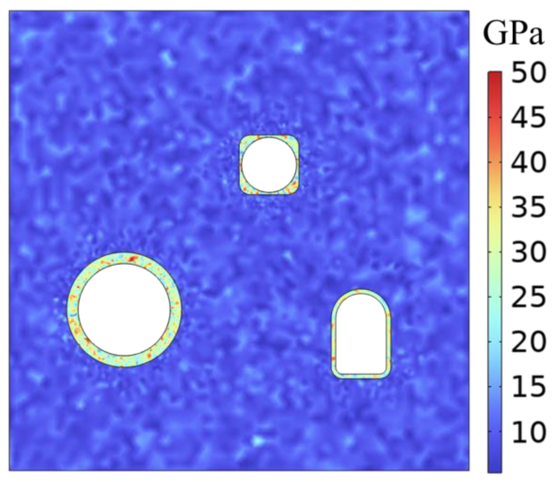
4. Mechanical Response of Chamber Boundary during One Cycle

For other parameters in this study, please refer to Table 3 [21]. During the operation of compressed air energy storage chambers, from the perspective of material strength, it is the energy storage chamber that generates high tensile stress when storing gas. When the gas pressure in the storage chamber is at a low level, the surrounding rock may also experience significant compressive stress and damage. However, materials may sometimes still pose risks due to displacement deformation issues even when they meet the strength standards. Therefore, this section mainly focuses on analyzing the changes in the stress and displacement of the innermost boundary in the chamber group under the condition of one cycle of compressed air energy storage. Considering the influence of complex stress and strong heterogeneity, this article adopts the method of using the average boundary value to obtain the stress and displacement of the internal boundary when dealing with it. That is, the stress or displacement of the boundary is accumulated, and then the required stress and displacement are obtained by dividing the accumulated result by the length of the line.
For the convenience of analysis, this article expands the area where the circular chamber is excavated into a large circular chamber and backfills the square chamber into a small circular chamber, and the remaining coal mine chamber is called a horseshoe-shaped tunnel. For the above three types of geological conditions, the average displacement value under one cycle of compressed air energy storage is shown in Figure 5. It can be clearly observed that the displacement change value of the small circular chamber is the highest, reaching a peak of 0.24 mm, followed by the large circular chamber, reaching a peak of 0.18 mm. Although the horseshoe-shaped tunnel is not used as a gas storage chamber, it is still affected by the other two gas storage chambers, and the displacement change also shows obvious regularity, with a maximum displacement of 0.12 mm. It is very interesting that the large and small circular chambers reached their peak displacements at 8 h, at which point the inflation had just ended, while the horseshoe-shaped tunnel reached its peak displacement at 12 h, which happened to be the starting time for deflation. This phenomenon indicates that the horseshoe-shaped tunnel has a certain lag in deformation compared to the other two gas storage chambers.
Figure 6 shows the average maximum principal stress at the inner boundary of the energy storage chamber and the horseshoe-shaped roadway. It can be observed that the maximum principal stress during the operation of the gas storage chamber (large and small circular chambers) is in a “several” shape. After 8 h of inflation, the maximum principal stress still increases. This may be due to the high temperature of the gas storage chamber, which generates additional thermal stress through thermal conduction/convection. Therefore, during the 8–12 h storage stage, the maximum principal stress still rises. During the charging and discharging processes of energy storage chambers, the peak value of the large circular chamber is 14.75 MPa, and the peak value of the small circular chamber is 9.22 Mpa. Therefore, in the construction process of the gas storage chamber, the tensile strength of the material at the innermost boundary, especially the small circular chamber, needs to be carefully considered.
Figure 7 shows the average minimum principal stress at the inner boundary of the energy storage chamber and the horseshoe-shaped roadway. What can be observed is that the minimum principal stress pattern during the operation of gas storage chambers (large and small circular chambers) is still a “several” shape. It can be clearly observed that, regardless of the chamber, the minimum principal stress during the energy storage stage presents a large value, thus requiring the material to have a high compressive strength. Different internal boundaries all have their maximum values at the initial moment. On the inner surface of the sealing layer, the small circular chamber was subjected to a pressure of 52.81 MPa at time 0, the large circular chamber was subjected to a pressure of 41.68 MPa at time 0, and even the horseshoe-shaped tunnel was subjected to a pressure of 17.5 MPa at the initial moment.
The discussion in this section found that the average deformation of the small circular chamber is the highest with a peak value of 0.24 mm. The stress of the small circular chamber is also the most complex, with both the tensile and compressive stresses reaching their maximum values during the same period. Therefore, when constructing gas storage facilities, the most important consideration is the safety operation of the small circular chamber. As long as the small circular chamber can operate stably, the large circular chamber and the horseshoe-shaped roadway can basically meet the requirements throughout the entire operation stage. At the same time, this section mainly discusses the deformation and stress issues of the interior boundary of the chamber, while the temperature, deformation, and stress of the surrounding rock and the overall structure remain equally important.

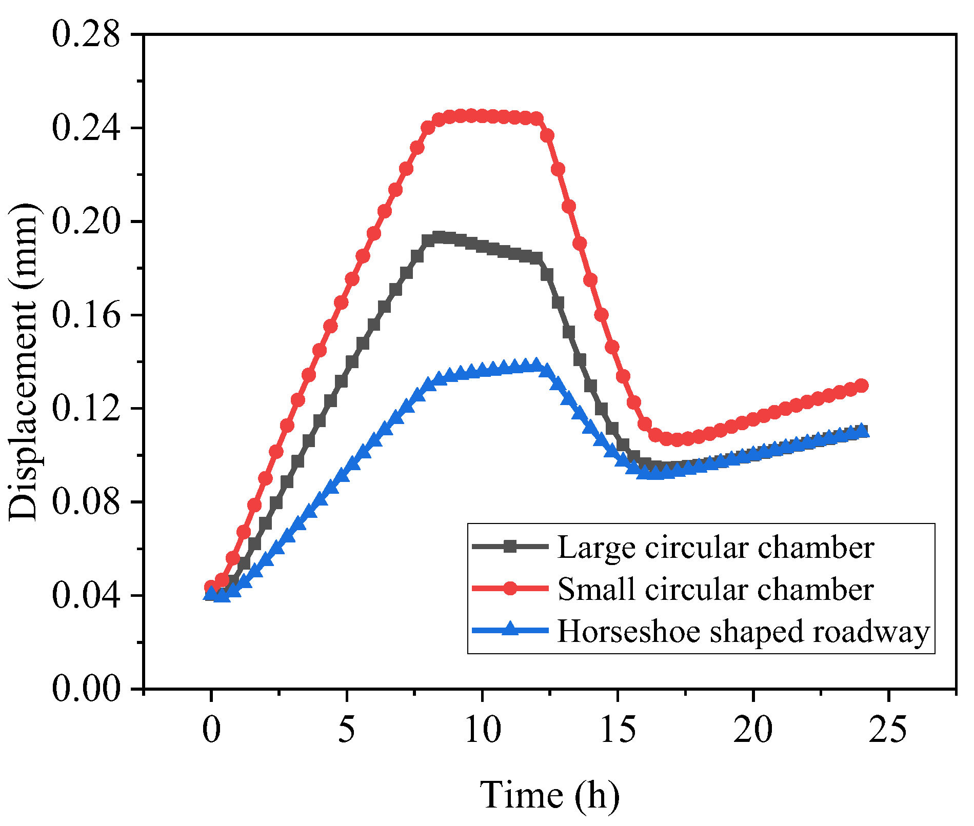
5. Overall Mechanical Responses of a Group of Chambers during One Cycle

In the entire process of compressed air energy storage, the steel lining acts as a sealing layer, as it not only has a sealing effect, but also a stress transfer effect. This means that the stress changes in the energy storage chamber will be transferred to the surrounding rock along the steel lining and concrete lining. The deformation and stress distribution of the surrounding rock are equally important. After significant deformation, damage, or failure of the surrounding rock due to excessive stress, the stability of the compressed air energy storage chamber can be significantly compromised, potentially leading to project failure. Thus, this section will primarily center on a comprehensive analysis and discussion of the mechanical response of the chamber group throughout a cycle of compressed air energy storage. Figure 8 shows the displacement variation cloud map of the entire chamber group.
It is worth noting that the time nodes that should be most concerned about displacement are the states of 0, 8, 16, and 24 h, which correspond to the completion of inflation, deflation, and the initial time of the next stage. Figure 8b shows the state when the inflation reaches 8 h. It is observed that, under the influence of ground stress, the peak direction of the displacement difference of the large circular chamber is mainly at a certain angle with the vertical direction, with a maximum displacement difference of 0.25 mm, while the small circular chamber is mainly distributed in the up and down directions. When running for 16 h, there was a small displacement strain connecting the large and small circular chambers at the top of the chamber. The occurrence of this situation is closely related to the in situ stress at that location. At the same time, due to the decrease in gas pressure inside the chamber, the upper coal seam will continuously compress the upper part of the chamber under the action of gravity, and concrete is used for support inside the chamber. This results in a smaller displacement in the upper part of the chamber, but a larger displacement in the lower part. However, after 24 h, the entire chamber group was basically in a stable small displacement state, with the main displacement being distributed on the upper side of the chamber group.
Scholars are also generally concerned about the state of temperature conduction changes at the end of inflation (8 h), the end of deflation (16 h), and the start of the second cycle (24 h). By observing the cloud map shown in Figure 9, it can be clearly observed that at the end of inflation, the inner boundary temperature of the large and small circular chambers is the highest, reaching 298.3 K. However, during deflation, the temperature begins to transfer internally due to heat conduction, and the highest temperature is mainly concentrated in the concrete lining layer. In contrast, the horseshoe-shaped tunnel has a certain increase in internal temperature due to its relationship with external ventilation (default external temperature is 23 degrees, which is 296.15 K). After 24 h, the highest temperature begins to transition from the concrete lining layer to the surrounding rock layer, and the temperature of the horseshoe-shaped tunnel is relatively high.
Considering the changes in stress, the most dangerous moments should be the end of inflation and the end of deflation. Therefore, three time points were selected for stress analysis, namely the end of inflation (8 h), the end of storage (12 h), and the end of deflation (16 h). At the same time, for the convenience of discussion, the stress magnitude of the steel lining sealing layer will not be considered in the subsequent analysis. This is because it was discussed in the above section. On the other hand, due to the excessive stress in the steel lining, when the stress in the steel lining is considered, the stress variation of other materials will no longer be significant. As shown in Figure 10, the variation in the maximum principal stress in the chamber group is shown. When the inflation is completed, the maximum tensile stress is mainly concentrated around the gas storage chamber. After the storage is completed, the maximum tensile stress value further increases. The reason for this is that the thermal stress generated by temperature after heat conduction leads to a further increase in the original stress. After the gas release is completed, the maximum tensile stress point shifts from the range of the energy storage chamber to the left and right sides of the horseshoe-shaped tunnel. This means that, at this time, the left and right sides of the horseshoe-shaped tunnel are more prone to damage. Therefore, in practical engineering, not only should the reinforcement scheme of the energy storage chamber be considered, but also the left and right sides of the horseshoe-shaped tunnel still need to be reinforced.
Figure 11 shows the variation in the minimum principal stress of the chamber group. The graph shows that the range of minimum principal stress variation in the horseshoe-shaped tunnel is relatively small, and the stress distribution remains basically unchanged throughout the entire energy storage cycle. However, the upper and lower ends of the horseshoe-shaped channel are mainly composed of compressive stresses and may be the gathering area of high-pressure stresses. During the energy storage process, the minimum principal stresses of both large and small circular chambers decrease to some extent, with the most significant change in the principal stresses in the large circular chamber. After the gradual unloading of high-pressure gas, the extreme (maximum) value of the minimum principal stress begins to be determined by the ground stress, and the points of maximum stress are located on both sides of the chamber.

6. Conclusions

This study conducted an analysis of the compressed air energy storage process for a group of chambers by using thermal-solid coupling theory. It delved into the transient mechanical response of the compressed air energy storage chamber group within a complete cycle, offering valuable insights for similar engineering endeavors. Through these investigations, the following conclusions emerged:
(1)
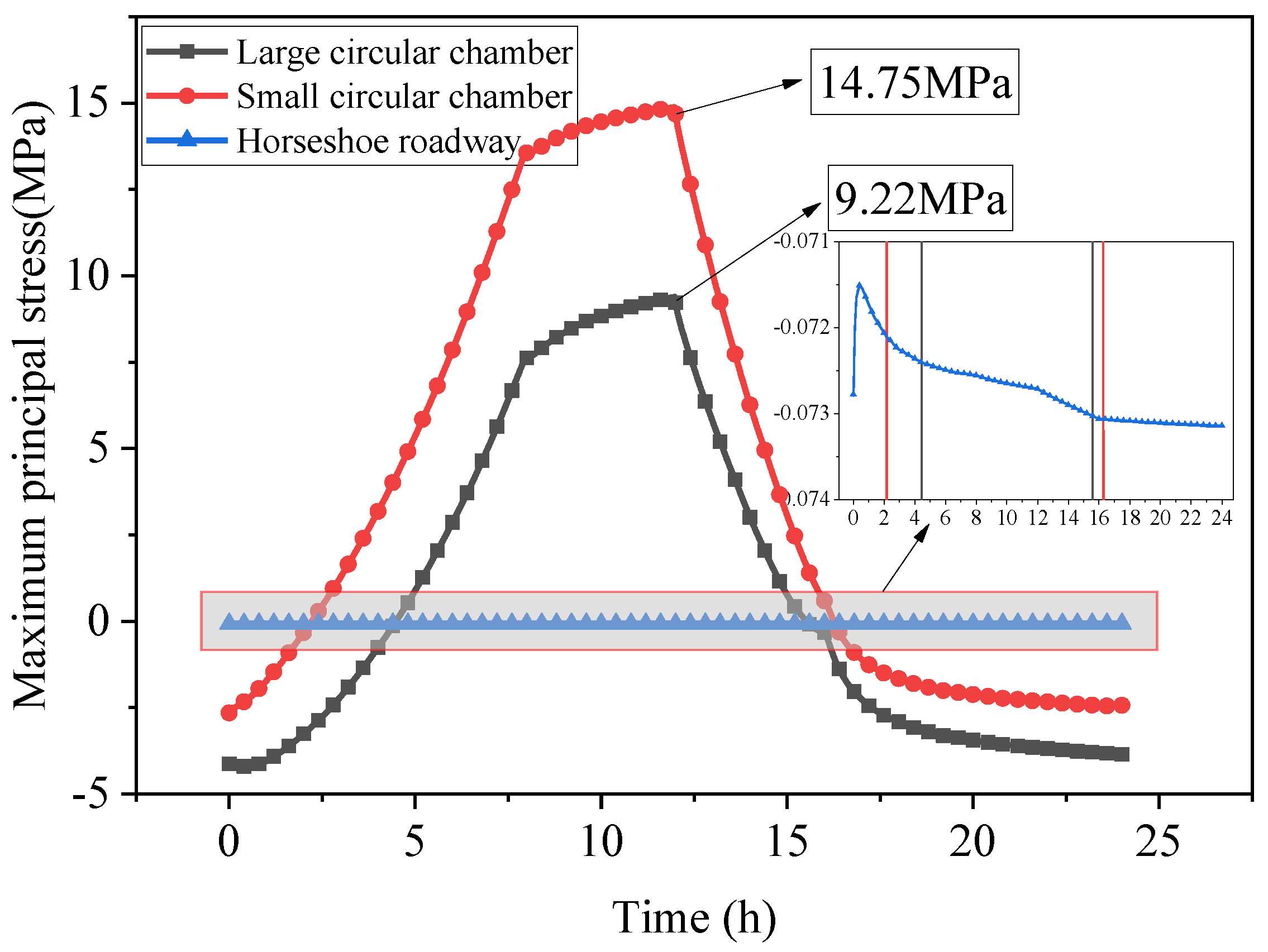
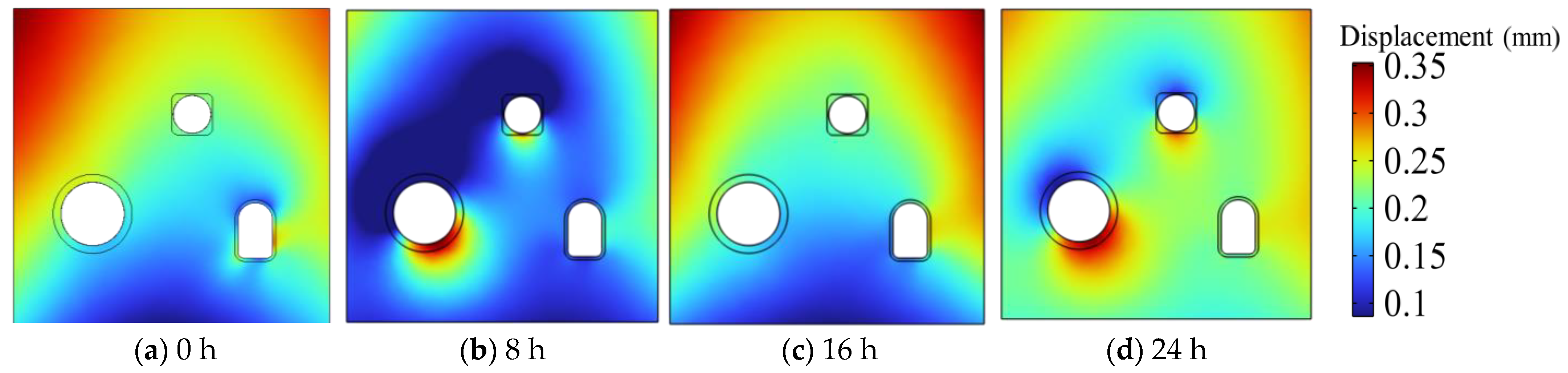
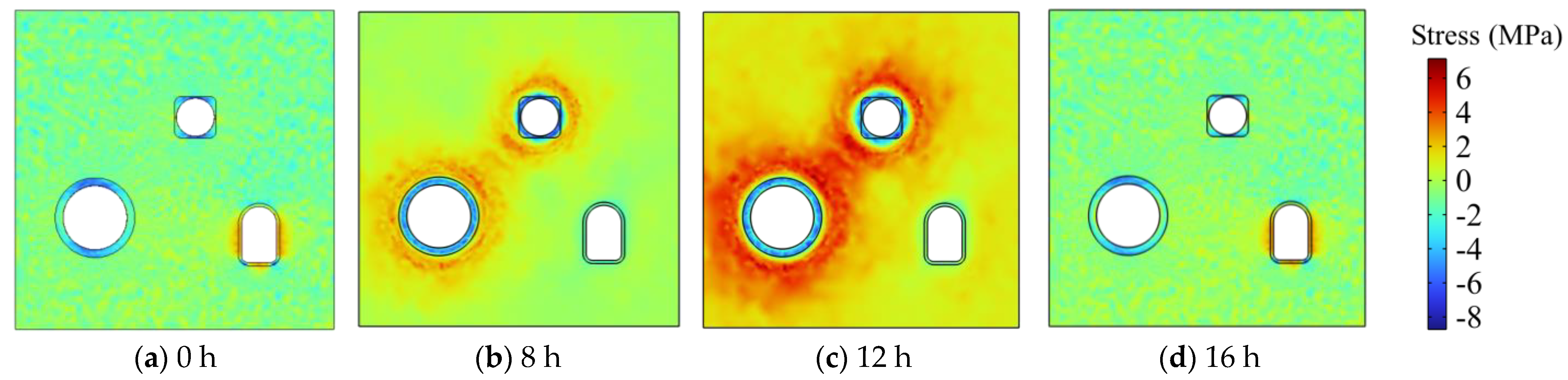
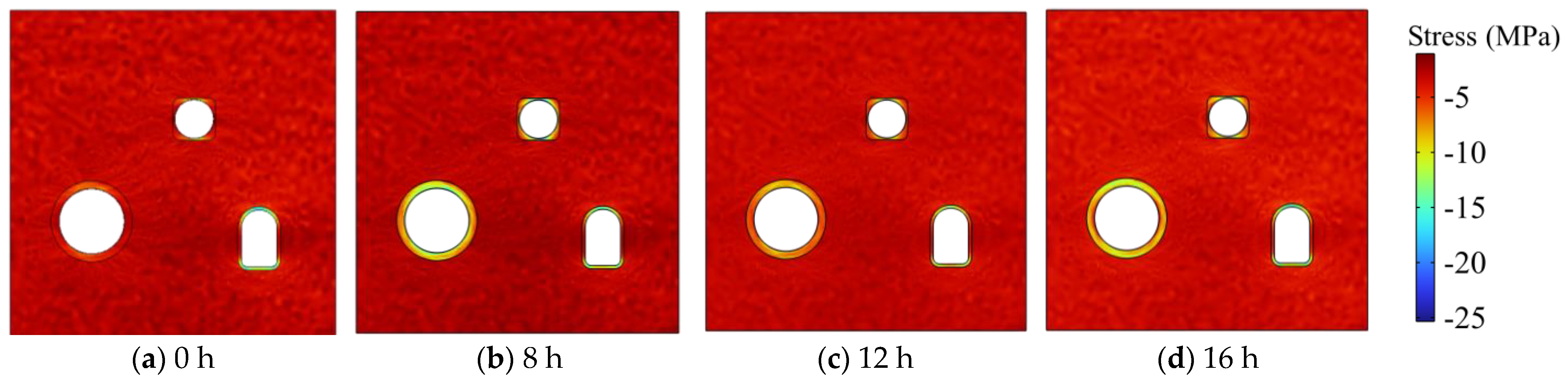
The small circular chamber exhibited the most significant deformation, with an average displacement peak of 0.24 mm. This was followed by the large circular chamber and the horseshoe-shaped tunnel. The maximum displacement of the boundary between the small and large circular chambers peaked after inflation was completed. Peak displacements of the large and small circular chambers were concentrated at the chamber top, while the horseshoe-shaped roadway peaked after deflation was completed. This suggests a lag in displacement change for the horseshoe-shaped roadway.
(2)
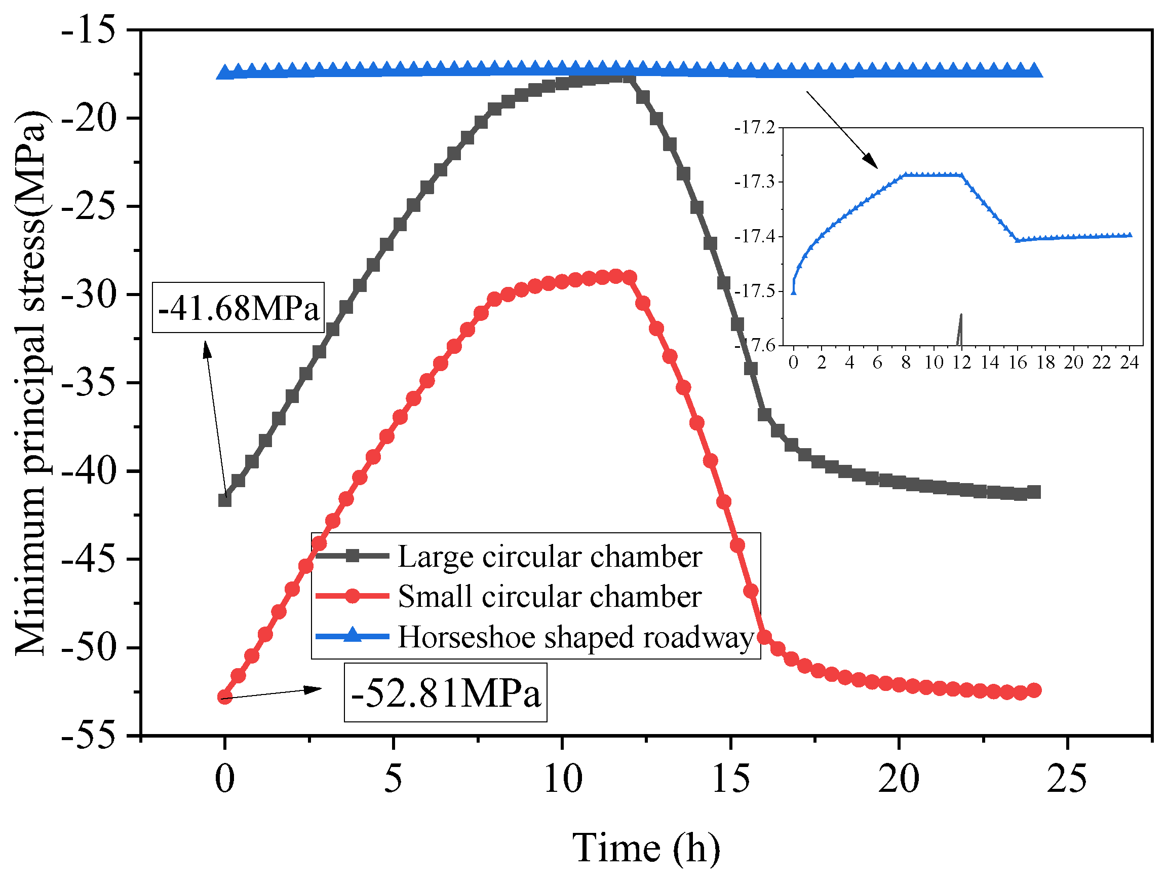
The small circular chamber exhibited maximum tensile and compressive stresses. At the end of inflation and deflation, the maximum tensile stress primarily concentrated around the gas storage chamber. After deflation, the point of maximum tensile stress shifted to the left and right sides of the horseshoe-shaped tunnel.
(3)
The stress and displacement of the small circular chamber indicate that it is more prone to failure. Additionally, measures should be taken to reinforce the horseshoe-shaped roadway, particularly its left and right sides, to prevent damage caused by tensile stress during deflation. Reinforcement of the upper and lower sides is also necessary to prevent damage from compressive stress during deflation.
(4)
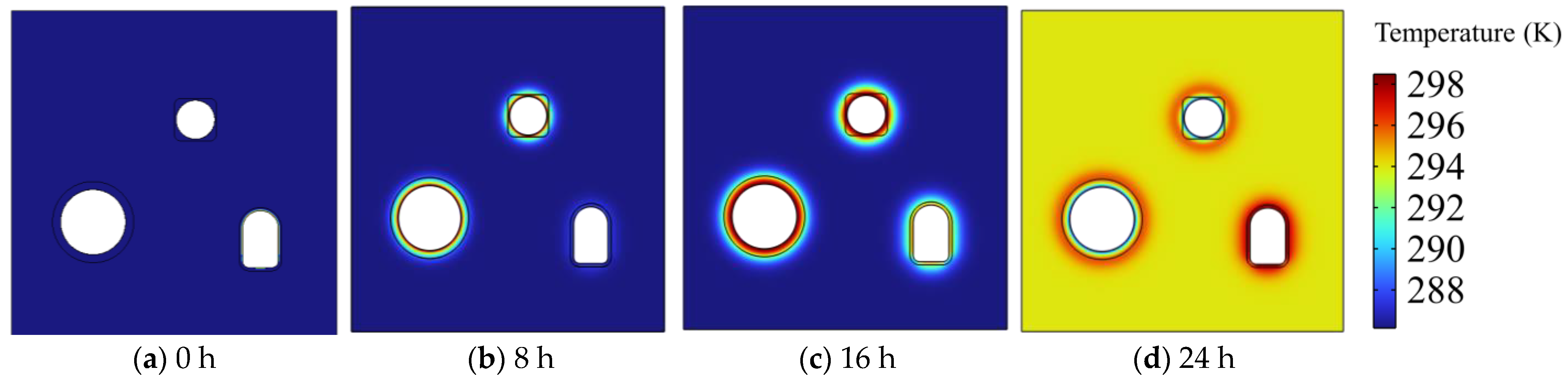
The continuous charging and discharging of the two chambers of the gas storage tank in the energy storage cavern group results in continuous temperature changes throughout the entire cycle. Therefore, when considering multiple cycles, the influence of thermal stress should be taken into account. Additionally, the horseshoe-shaped roadway remains connected to external air, leading to temperature migration and changes. This study observed a similar temperature delay phenomenon during the calculations that is consistent with the understanding that temperature requires time to transfer when it changes.

Author Contributions

Conceptualization, F.L. (Fuqing Li) and F.L. (Fufeng Li); methodology, F.L. (Fuqing Li) and R.S.; software, F.L. (Fuqing Li) and R.S.; validation, F.L. (Fuqing Li), R.S., J.Z., and X.L.; formal analysis, Q.S.; investigation, J.Z.; resources, Y.L.; data curation, R.S. and Y.L.; writing—original draft preparation, R.S. and Y.D.; visualization, L.S.; supervision, L.S. and Y.J. All authors have read and agreed to the published version of the manuscript.

Funding

The authors are grateful for the financial support from the Graduate Innovation Program of China University of Mining and Technology (2023WLJCRCZL046), the Postgraduate Research & Practice Innovation Program of Jiangsu Province (KYCX23_2660), and the Key R&D Program of Jiangsu, China (BE2022156).

Data Availability Statement

The data used to support the findings of this study are available from the corresponding author upon request.

Conflicts of Interest

Author Fufeng Li was employed by the Shanghai Urban Construction Municipal Engineering (Group) Co., Ltd., Jianjie Zheng and Lan Shen were employed by Shanghai Tunnel Engineering Co., Ltd., Qiang Sun and Yinhang Duan were employed by China Coal (Tianjin) Underground Engineering Intelligence Research Institute Co., Ltd. The remaining authors declare that the research was conducted in the absence of any commercial or financial relationships that could be construed as a potential conflict of interest.

References

  1. Gielen, D.; Boshell, F.; Saygin, D.; Bazilian, M.D.; Wagner, N.; Gorini, R. The role of renewable energy in the global energy transformation. Energy Strategy Rev. 2019, 24, 38–50. [Google Scholar] [CrossRef]
  2. Li, J.; Wang, G.; Li, Z.; Yang, S.; Chong, W.T.; Xiang, X. A review on development of offshore wind energy conversion system. Int. J. Energy Res. 2020, 44, 9283–9297. [Google Scholar] [CrossRef]
  3. Wang, S.; Sun, L.; Iqbal, S. Green financing role on renewable energy dependence and energy transition in E7 economies. Renew. Energy 2022, 200, 1561–1572. [Google Scholar] [CrossRef]
  4. Yang, J.; Wang, J.; Hu, B. Numerical analysis of the impacts of multiscale fractures on geothermal reservoir capacity. J. Energy Eng. 2023, 149, 04023046. [Google Scholar] [CrossRef]
  5. Wu, X.; Cai, M.; Wu, X.; Zhang, K.; Yin, Z.; Zhu, Y. Impact of well placement and flow rate on production efficiency and stress field in the fractured geothermal reservoirs. Deep Undergr. Sci. Eng. 2023. [Google Scholar] [CrossRef]
  6. Ye, Z.; Wang, J.G.; Yang, J. A multi-objective optimization approach for a fault geothermal system based on response surface method. Geothermics 2024, 117, 102887. [Google Scholar] [CrossRef]
  7. Behabtu, H.A.; Vafaeipour, M.; Kebede, A.A.; Berecibar, M.; Van Mierlo, J.; Fante, K.A.; Messagie, M.; Coosemans, T. Smoothing intermittent output power in grid-connected doubly fed induction generator wind turbines with li-ion batteries. Energies 2023, 16, 7637. [Google Scholar] [CrossRef]
  8. Sun, R.; Wang, J. Effects of in situ stress and multiborehole cluster on hydraulic fracturing of shale gas reservoir from multiscale perspective. J. Energy Eng. 2024, 150, 04024002. [Google Scholar] [CrossRef]
  9. Li, P.; Wang, J.; Liang, W.; Sun, R. An analytical and numerical analysis for hydraulic fracture propagation through reservoir interface in coal-measure superimposed reservoirs. Sustainability 2023, 15, 4597. [Google Scholar] [CrossRef]
  10. Liang, W.; Wang, J.; Li, P.; Leung, C.; Goh, S.; Sang, S. New insight to interlayer interference during three-gas co-production based on a wellbore–reservoir coupling model. Nat. Resour. Res. 2023, 32, 2037–2052. [Google Scholar] [CrossRef]
  11. Liang, W.; Wang, J.G.; Leung, C.F.; Goh, S.; Li, P. Impact of crossflow and two-phase flow on gas production from stacked deposits. Energy Fuels 2023, 37, 8935–8948. [Google Scholar] [CrossRef]
  12. Martirosyan, A.V.; Ilyushin, Y.V. The Development of the Toxic and Flammable Gases Concentration Monitoring System for Coalmines. Energies 2022, 15, 8917. [Google Scholar] [CrossRef]
  13. Wang, J.; Wang, H.; Wang, X.; Yang, S.; Wu, H.; Leung, C.; Tian, J. A multiphysical-geochemical coupling model for caprock sealing efficiency in CO2 geosequestration. Deep Undergr. Sci. Eng. 2023, 2, 188–203. [Google Scholar] [CrossRef]
  14. Bekebrok, H.; Langnickel, H.; Pluta, A.; Zobel, M.; Dyck, A. Underground storage of green hydrogen—boundary conditions for compressor systems. Energies 2022, 15, 5972. [Google Scholar] [CrossRef]
  15. Vandeginste, V.; Ji, Y.; Buysschaert, F.; Anoyatis, G. Mineralogy, microstructures and geomechanics of rock salt for underground gas storage. Deep Undergr. Sci. Eng. 2023, 2, 129–147. [Google Scholar] [CrossRef]
  16. Qi, X.; Guo, P.; Guo, Y.; Liu, X.; Zhou, X. Understanding energy efficiency and its drivers: An empirical analysis of China’s 14 coal intensive industries. Energy 2020, 190, 116354. [Google Scholar] [CrossRef]
  17. Li, R.; Tang, B.J.; Yu, B.; Liao, H.; Zhang, C.; Wei, Y.M. Cost-optimal operation strategy for integrating large scale of renewable energy in China’s power system: From a multi-regional perspective. Appl. Energy 2022, 325, 119780. [Google Scholar] [CrossRef]
  18. Li, J.; Ho, M.S.; Xie, C.; Stern, N. China’s flexibility challenge in achieving carbon neutrality by 2060. Renew. Sustain. Energy Rev. 2022, 158, 112112. [Google Scholar] [CrossRef]
  19. Wu, D.; Wang, J.G.; Hu, B.W.; Yang, S.Q. A coupled thermo-hydro-mechanical model for evaluating air leakage from an unlined compressed air energy storage cavern. Renew. Energy 2020, 146, 907–920. [Google Scholar] [CrossRef]
  20. Chen, X.; Wang, J.G. Stability analysis for compressed air energy storage cavern with initial excavation damage zone in an abandoned mining tunnel. J. Energy Storage 2022, 45, 103725. [Google Scholar] [CrossRef]
  21. Sun, R.; Wang, J.; Zhang, K.; Li, F.; Ding, X.; Guo, Q. Stress redistribution in a multilayer chamber for compressed air energy storage in abandoned coalmine: Elastic analytical insights and material choice. Energy Sci. Eng. 2023, 11, 4198–4223. [Google Scholar] [CrossRef]
  22. Polański, K. Influence of the variability of compressed air temperature on selected parameters of the deformation-stress state of the rock mass around a CAES salt cavern. Energies 2021, 14, 6197. [Google Scholar] [CrossRef]
  23. Xu, M.; Wang, X.; Wang, Z.; Zhao, P.; Dai, Y. Preliminary design and performance assessment of compressed supercritical carbon dioxide energy storage system. Appl. Therm. Eng. 2021, 183, 116153. [Google Scholar] [CrossRef]
  24. Rutqvist, J.; Kim, H.M.; Ryu, D.W.; Synn, J.H.; Song, W.K. Modeling of coupled thermodynamic and geomechanical performance of underground compressed air energy storage in lined rock caverns. Int. J. Rock Mech. Min. Sci. 2012, 52, 71–81. [Google Scholar] [CrossRef]
  25. Crotogino, F.; Mohmeyer, K.U.; Scharf, R. Huntorf CAES: More than 20 Years of Successful Operation. In Proceedings of the Solution Mining Research Institute (SMRI) Spring Meeting, Orlando, FL, USA, 15–18 April 2001; pp. 1–7. [Google Scholar]
  26. Olabi, A.G.; Wilberforce, T.; Ramadan, M.; Abdelkareem, M.A.; Alami, A.H. Compressed air energy storage systems: Components and operating parameters—A review. J. Energy Storage 2021, 34, 102000. [Google Scholar] [CrossRef]
  27. King, M.; Jain, A.; Bhakar, R.; Mathur, J.; Wang, J. Overview of current compressed air energy storage projects and analysis of the potential underground storage capacity in India and the UK. Renew. Sustain. Energy Rev. 2021, 139, 110705. [Google Scholar] [CrossRef]
  28. Stille, H.; Johansson, J.; Sturk, R. High pressure storage of gas in lined shallow rock caverns—Results from field tests. In Proceedings of the Rock Mechanics in Petroleum Engineering, Delft, The Netherlands, 29–31 August 1994. [Google Scholar]
  29. Chen, L.; Zheng, T.; Mei, S.; Xue, X.; Liu, B.; Lu, Q. Review and prospect of compressed air energy storage system. J. Mod. Power Syst. Clean Energy 2016, 4, 529–541. [Google Scholar] [CrossRef]
  30. Tong, Z.; Cheng, Z.; Tong, S. A review on the development of compressed air energy storage in China: Technical and economic challenges to commercialization. Renew. Sustain. Energy Rev. 2021, 135, 110178. [Google Scholar] [CrossRef]
  31. Xu, Y.; Zhou, S.W.; Xia, C.C.; Zhao, H.; Xue, X. Three-dimensional thermo-mechanical analysis of abandoned mine drifts for underground compressed air energy storage: A comparative study of two construction and plugging schemes. J. Energy Storage 2021, 39, 102696. [Google Scholar] [CrossRef]
  32. Li, J.; Wan, J.; Liu, H.; Jurado, M.J.; He, Y.; Yuan, G.; Xia, Y. Stability analysis of a typical salt cavern gas storage in the Jintan area of China. Energies 2022, 15, 4167. [Google Scholar] [CrossRef]
  33. Lyu, X.; Yang, K.; Fang, J. Utilization of resources in abandoned coal mines for carbon neutrality. Sci. Total Environ. 2022, 822, 153646. [Google Scholar] [CrossRef] [PubMed]
  34. Perazzelli, P.; Anagnostou, G. Design issues for compressed air energy storage in sealed underground cavities. J. Rock Mech. Geotech. Eng. 2016, 8, 314–328. [Google Scholar] [CrossRef]
  35. Xia, C.C.; Zhou, Y.; Zhou, S.W.; Zhang, P.; Wang, F. A simplified and unified analytical solution for temperature and pressure variations in compressed air energy storage caverns. Renew. Energy 2015, 74, 718–726. [Google Scholar] [CrossRef]
  36. Jiang, Z.; Li, P.; Tang, D.; Zhao, H.; Li, Y. Experimental and numerical investigations of small-scale lined rock cavern at shallow depth for compressed air energy storage. Rock Mech. Rock Eng. 2020, 53, 2671–2683. [Google Scholar] [CrossRef]
  37. Wan, F.; Jiang, Z.; Tian, X.; Konietzky, H.; Xiao, Z. A thermo-hydro-mechanical damage model for lined rock cavern for compressed air energy storage. J. Energy Storage 2024, 78, 110186. [Google Scholar] [CrossRef]
  38. Damjanac, B.; Carranza-Torres, C.; Dexter, R. Technical review of the lined rock caverns (LRC) concept and design methodology steel liner response. Minnesota 2002, 32, 59–70. [Google Scholar]
  39. Kim, H.M.; Rutqvist, J.; Jeong, J.H.; Choi, B.H.; Ryu, D.W.; Song, W.K. Characterizing excavation damaged zone and stability of pressurized lined rock caverns for underground compressed air energy storage. Rock Mech. Rock Eng. 2012, 46, 1113–1124. [Google Scholar] [CrossRef]
  40. Mortazavi, A.; Molladavoodi, H. A numerical investigation of brittle rock damage model in deep underground openings. Eng. Fract. Mech. 2012, 90, 101–120. [Google Scholar] [CrossRef]
  41. Kushnir, R.; Dayan, A.; Ullmann, A. Temperature and pressure variations within compressed air energy storage caverns. Int. J. Heat Mass Transf. 2012, 55, 5616–5630. [Google Scholar] [CrossRef]
  42. Hu, B.W.; Wang, J.G.; Li, Z.Q.; Wang, H.M. Evolution of fractal dimensions and gas transport models during the gas recovery process from a gractured shale reservoir. Fractals 2019, 27, 1950129. [Google Scholar] [CrossRef]
  43. Martino, J.B.; Chandler, N.A. Excavation-induced damage studies at the underground research laboratory. Int. J. Rock Mech. Min. Sci. 2004, 41, 1413–1426. [Google Scholar] [CrossRef]
  44. Kim, H.M.; Rutqvist, J.; Ryu, D.W.; Choi, B.H.; Sunwoo, C.; Song, W.K. Exploring the concept of compressed air energy storage (CAES) in lined rock caverns at shallow depth: A modeling study of air tightness and energy balance. Appl. Energy 2012, 92, 653–667. [Google Scholar] [CrossRef]
  45. Wang, Z.H.; Yang, S.L.; Tang, Y.S. Mechanical behavior of different sedimentary rocks in the Brazilian test. Bull. Eng. Geol. Environ. 2020, 79, 5415–5432. [Google Scholar] [CrossRef]
Figure 1. Function image of Fi and Fe within one cycle.
Energies 17 00953 g001
Figure 2. Chamber group model.
Energies 17 00953 g002
Figure 3. Distribution map of elastic modulus of energy storage chamber group.
Energies 17 00953 g003
Figure 4. Result verification comparison diagram. (a) Displacement diagram. (b) Temperature diagram. Data from [20].
Energies 17 00953 g004
Figure 5. Displacement variation diagram of energy storage chamber and horseshoe-shaped roadway.
Energies 17 00953 g005
Figure 6. Maximum principal stress variation diagram of energy storage chamber and horseshoe-shaped roadway.
Energies 17 00953 g006
Figure 7. Minimum principal stress variation diagram of energy storage chamber and horseshoe-shaped roadway.
Energies 17 00953 g007
Figure 8. Overall displacement variation diagram of the chamber group.
Energies 17 00953 g008
Figure 9. Overall temperature variation diagram of the chamber group.
Energies 17 00953 g009
Figure 10. Diagram of the overall maximum principal stress variation in the chamber group.
Energies 17 00953 g010
Figure 11. The overall minimum principal stress variation diagram of the chamber group.
Energies 17 00953 g011
Table 1. Some properties of the 12th coal mining area.
PositionLithology and ChangesRock TypeStability
RoofThe direct roof is mainly composed of mudstone and sandy mudstone, with a thickness of 1.54–10.8 m and an average of 3.96 m. The thickness of sandstone is 5.99–22.1 m with an average of 12.9 m.MudstoneUnstable to moderately stable
Sandy mudstone
FloorThe direct bottom plate is limestone with a thickness of 0–2.45 m. The pseudo bottom is mudstone with a thickness of 0.1 m to 0.6 m.LimestoneModerately stable to sturdy
Table 2. Basic parameters used in numerical simulation models.
Parameters (Variables, Units)Numerical ValueParameter Source
Chamber radius, R1 (m)2.5Wu et al. [19]
Chamber length, H (m)5.093 × 10³Wu et al. [19]
Surface area of the chamber, Ac (m2)8 × 10⁴Wu et al. [19]
Chamber volume, V (m3)1 × 10⁵Wu et al. [19]
Charge gas temperature, Ti (K)294.65Wu et al. [19]
Gas mass flow rate, mie (kg/s)100Wu et al. [19]
Heat exchange coefficient, hc (W/(m2·K))30Wu et al. [19]
Initial pressure of the chamber, Pc0 (Pa)5 × 10⁶Wu et al. [19]
Initial temperature of the chamber, T0 (K)286.15Wu et al. [19]
Initial permeability of rocks, k0 = kd0 (m2)1 × 10⁻¹⁷Martino et al. [43]
Initial porosity of rocks, ϕ0 = ϕd00.01Kim et al. [44]
Young’s modulus of rock, E = Ed (GPa)13.5Sun et al. [21]
Poisson’s ratio of rocks, ν0.3Kim et al. [44]
Rock density, ρs (kg/m3)2700Kim et al. [44]
Tensile strength of rocks, σt (MPa)13.4Wang et al. [45]
Rock thermal expansion coefficient, αT (1/K)1 × 10−5Kim et al. [44]
Rock thermal conductivity, βr (J/(m·s·K))3Kim et al. [44]
Rock specific heat capacity, Cr (J/(kg·K))0.9 × 103Kim et al. [44]
Time point, t1 (h)8Kim et al. [44]
Time point, t2 (h)12Kim et al. [44]
Time point, t3 (h)16Kim et al. [44]
Time point, tp (h)24Kim et al. [44]
Table 3. Basic parameters used in numerical simulation models.
Sealing LayerLining LayerRock Layer
E (GPa)2103513.7
v0.270.250.24
ρ (kg/m3)780025002000
α (1/K)8 × 10−61.2 × 10−51.0 × 10⁻⁵
Disclaimer/Publisher’s Note: The statements, opinions and data contained in all publications are solely those of the individual author(s) and contributor(s) and not of MDPI and/or the editor(s). MDPI and/or the editor(s) disclaim responsibility for any injury to people or property resulting from any ideas, methods, instructions or products referred to in the content.

