

Latent Thermal Energy Storage System for Heat Recovery between 120 and 150 °C: Material Stability and Corrosion †


Abstract
1. Introduction
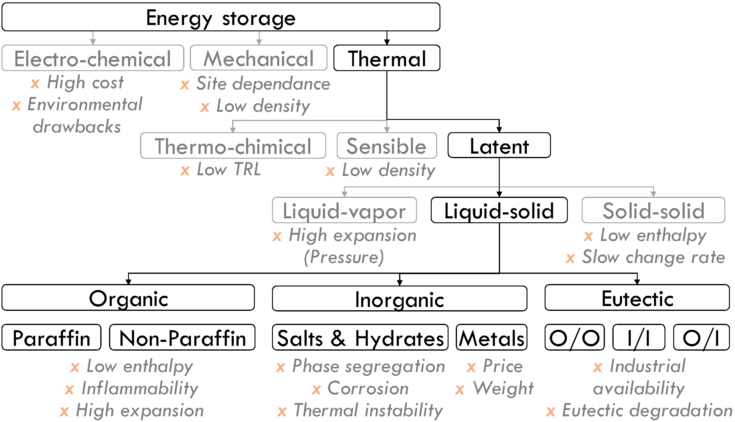
2. Phase Change Materials Screening and Selection
2.1. Selection Criteria
- Physical: besides the suitable transition temperature, the PCM should have:
- -
- High volumetric enthalpy (high latent heat and high density) to provide high-density storage. The value of 50 kWh·m−3 was taken as a reference. It corresponds to the variation enthalpy of water in a temperature range of approximately 0–43 °C;
- -
- High thermal conductivity to increase the heat transfer and provide high thermal storage\discharge power (may be optimized by the system geometry);
- -
- Low thermal expansion coefficient to avoid mechanical stress on PCM envelope;
- -
- Good phase equilibrium (no segregation during phase change), as phase segregation during transition disrupt heat transfer and can be partially irreversible;
- -
- No supercooling that delays crystallization.
- Chemical:
- -
- Long-term chemical stability to avoid performance degradation through thermal cycling;
- -
- Compatibility with enveloping materials to avoid corrosion;
- -
- No toxicity nor fire hazards.
- Economics:
- -
- PCM should be industrially available in large quantities;
- -
- For a cost-effective storage system, the PCM price should remain affordable. This is highly dependent on the targeted application: for a short-term storage (about 3 cycles per day), the International Renewable Energy Agency (IRENA) estimated a viable investment cost at 225 EUR·KWh−1 for the whole system [27]. Accounting for approximately 45% of this investment for the phase change material [28], its cost should remain under 100 EUR·KWh−1.
2.2. Materials Screening
- Metals, for their high costs. Two PCMs fit in the temperature range [30]: Indalloys 255 (55.5%mBi + 44.5%mPb, toxic) and 281 (58%mBi + 42%mSn), with the respective melting temperatures of 125 °C and 138 °C. They show a similar volume enthalpy variation to organic PCMs (respectively, 58 and 107 kWh·m−3), but their thermal conductivity is ~100 higher, supporting higher power.
- Eutectics, for their complex industrial production which hinders a precise and stable eutectic. Five PCMs could have been selected for their melting temperature [17,31]: 30%mLiNO₃ + 18%mNaNO₃ + 52%mKNO₃ (120 °C), 33%mLiNO₃ + 67%mKNO₃ (125 °C), 38.2%mLiNO₃ + 61.8%mCO(NH2)2 (125 °C), 44%mCa(NO₃)₂ + 44%mNaNO₃ + 12%mKNO₃ (140 °C), and 40%mNaNO₂ + 7%mNaNO₃ + 53%mKNO₃ (142 °C).
- High cost (- -): mandelic acid, valporic acid, suberic acid, methyl-4′-acetanilide [30], chlorobenzoic acid, and xylose-L;
- Early damage (decomposition temperature closer than 20 °C to the melting temperature): urea, malonic acid, maleic acid, DL-malic acid, trans cinamic acid, fructose-D, and glucose-D;
- Hazardousness (flammability, toxicity): picric acid, benzamide, phenacetine, and anthranilic acid;
- Significant supercooling (more than 30 °C): erythritol (despite a very attractive latent heat) and tromethanol (in addition to a high cost) [36].

| Name | Formula | ρ [kg·m−3] | Tm [°C] | ∆Hm [kJ·kg−1] | ΔHm, vol [kWh·m−3] | N° CAS | Price [EUR kWh−1] | Comments | Ref |
|---|---|---|---|---|---|---|---|---|---|
| Erythritol | C4H10O4 | 1480 | 118–120 | 340 | 140 | 149-32-6 | + + + | Supercooling > 80 °C | [36] |
| Succinic anhydride acid | C4H4O3 | 1560 | 118–121 | 206 | 89 | 108-30-5 | + + | * | |
| Mandelic acid | C6H5CH(OH)CO2H | 1300 | 118–121 | 161 | 58 | 90-64-2 | - - | High cost | [30] |
| Valporic acid | C₈H₁₆O₂ | 904 | 120 | 203 | 51 | 99-66-1 | - - | High cost | [30] |
| Benzoic acid | C₇H₆O₂ | 1266 | 121.7 | 143 | 50 | 65-85-0 | + + | Supercooling: 22 °C | * |
| Picric acid | C6H3N3O7 | 1760 | 122 | 75 | 37 | 88-89-1 | Flash point 150 °C, explosive | * | |
| HDPE | (C₂H₄)n | 940 | 125 | 167 | 44 | 9002-88-4 | Enthalpy < 50 kWh·m−3 | [35] | |
| Stilbene | C₁₄H₁₂ | 970 | 126 | 167 | 45 | 103-30-0 | Enthalpy < 50 kWh·m−3 | * | |
| Benzamid | C₉H₇NO | 1341 | 127.2 | 169 | 63 | 55-21-0 | Toxic | * | |
| Tromethamine/Tromethanol | C4H11NO3 | 1353 | 131 | 285 | 107 | 77-86-1 | - | Supercooling: 66 °C, High cost | [36] |
| Anydride phthalic | C₈H₄O₃ | 1530 | 131 | 159 | 68 | 85-44-9 | + + + | Supercooling: 23 °C | [38] |
| Sebacic acid | C₁₀H₁₈O₄ | 1209 | 131–133 | 243 | 82 | 111-20-6 | + + | [39] | |
| Maleic acid | C₄H₄O₄ | 1590 | 131–140 | 235 | 104 | 110-16-7 | Decomposition ~145 °C | * | |
| DL- malic acid | C₄H₆O₅ | 1601 | 131–140 | 225 | 100 | 6915-15-7 | Decomposition ~150 °C | * | |
| Urea | CO(NH₂)₂ | 1323 | 132 | 251 | 92 | 57-13-6 | Low stability | * | |
| Malonic acid | C₃H₄O₄ | 1620 | 132–136 | 141-82-2 | Decomposition ~135 °C | * | |||
| Trans cinnamic acid | C₉H₈O₂ | 1250 | 133 | 153 | 53 | 140-10-3 | Decomposition ~146 °C | * | |
| Phenacetin | C₁₀H₁₃NO₂ | 1240 | 134 | 175 | 60 | 62-44-2 | Toxic | * | |
| Chrolobenzoic acid | C7H5ClO2 | 1540 | 140 | 164 | 70 | 118-91-2 | - - | High cost | * |
| Suberic acid | C₈H₁₄O₄ | 1020 | 141–144 | 245 | 69 | 505-48-6 | - - | High cost | [30] |
| Dimethyl terephtalate | C₁₀H₁₀O₄ | 1290 | 142 | 170 | 61 | 120-61-6 | + + | * | |
| Fructose-D | C₆H₁₂O₆ | 1690 | 144–145 | 145 | 68 | 57-48-7 | Early degradation | * | |
| Isomalt | C12H24O11 | 1040 | 145 | 170 | 71 | 64519-82-0 | - | [37] | |
| Trans-1,4-polybutadiene (TPB) | C4H6 | 1010 | 145 | 144 | 40 | 25038-44-2 | Enthalpy < 50 kWh·m−3 | [6] | |
| Maltitol | C₁₂H₂₄O₁₁ | 1620 | 145–152 | 173 | 78 | 585-88-6 | + + + | * | |
| Methyl-4′-acetanilide | C9H11NO | 1370 | 146–151 | 180 | 69 | 103-89-9 | - - - | High cost | [30] |
| Lactitol | C₁₂H₂₄O₁₁ | 1690 | 146–152 | 135–149 | 70 | 585-86-4 | + + + | Industrial availability | * |
| Anthranilic acid | C6H4(NH2)COOH | 1410 | 147 | 148 | 58 | 118-92-3 | Flash point 150 °C | * | |
| Xylose-D | C₅H₁₀O₅ | 1525 | 147–151 | 216–280 | 118 | 58-86-6 | + + + | * | |
| Xylose -L | C₅H₁₀O₅ | 1525 | 147–151 | 213 | 90 | 609-06-3 | - - - | High cost | * |
| Glucose -D | C₆H₁₂O₆ | 1540 | 149–152 | 180 | 82 | 50-99-7 | Low stability | * | |
| Adipic acid | C₆H₁₀O₄ | 1360 | 151–155 | 260 | 98 | 124-04-9 | + + + | * |
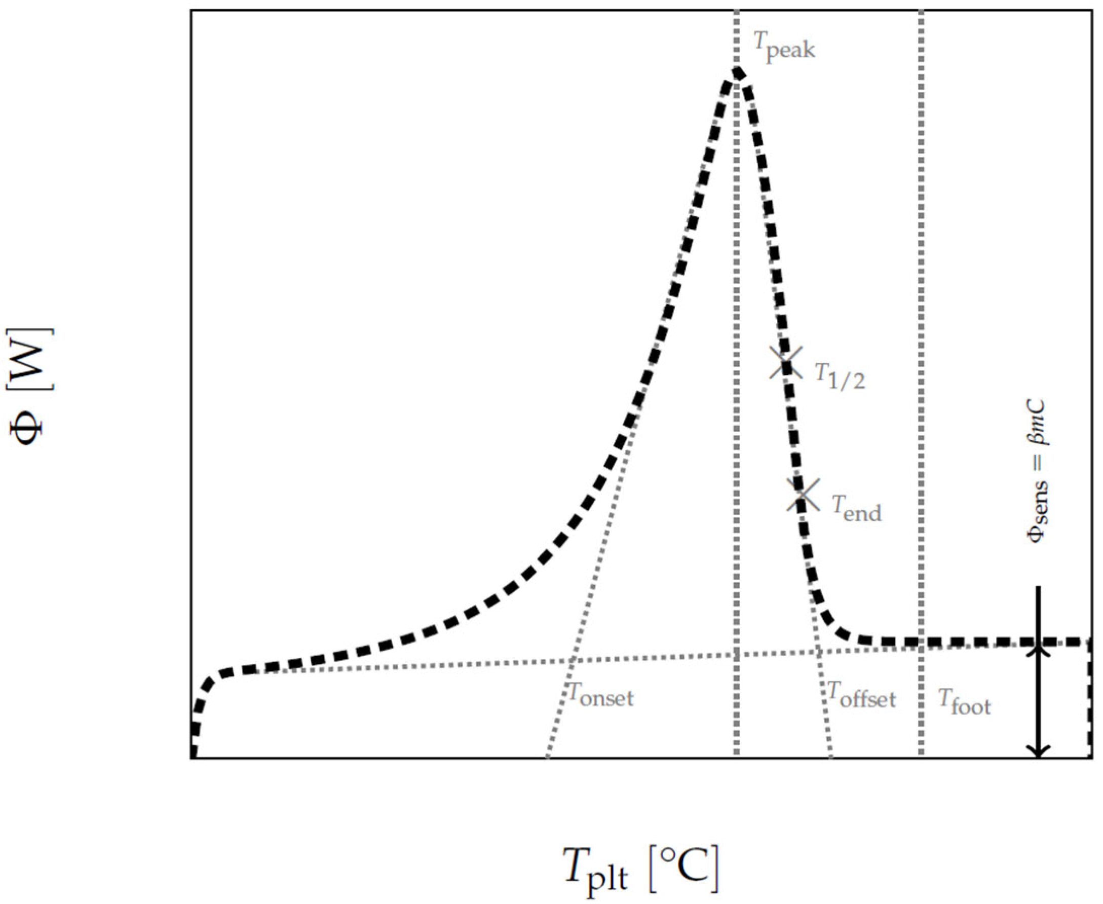
2.3. Calorimetric Analysis
2.3.1. Material & Method
Differential Scanning Calorimetry (DSC)
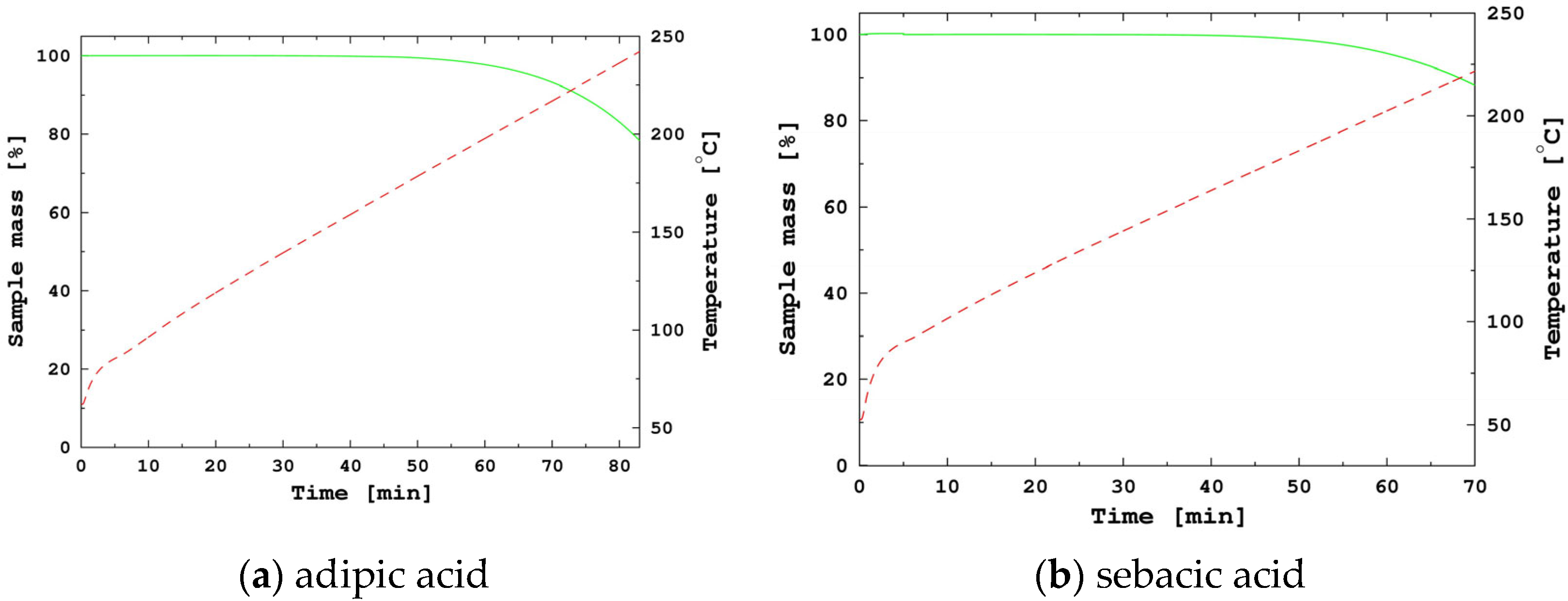
Thermogravimetry Analysis (TGA)
- A 10 min isothermal step at 35 °C below the melting temperature;
- A 2 °C·min−1 slope up to 100 °C above the melting temperature.
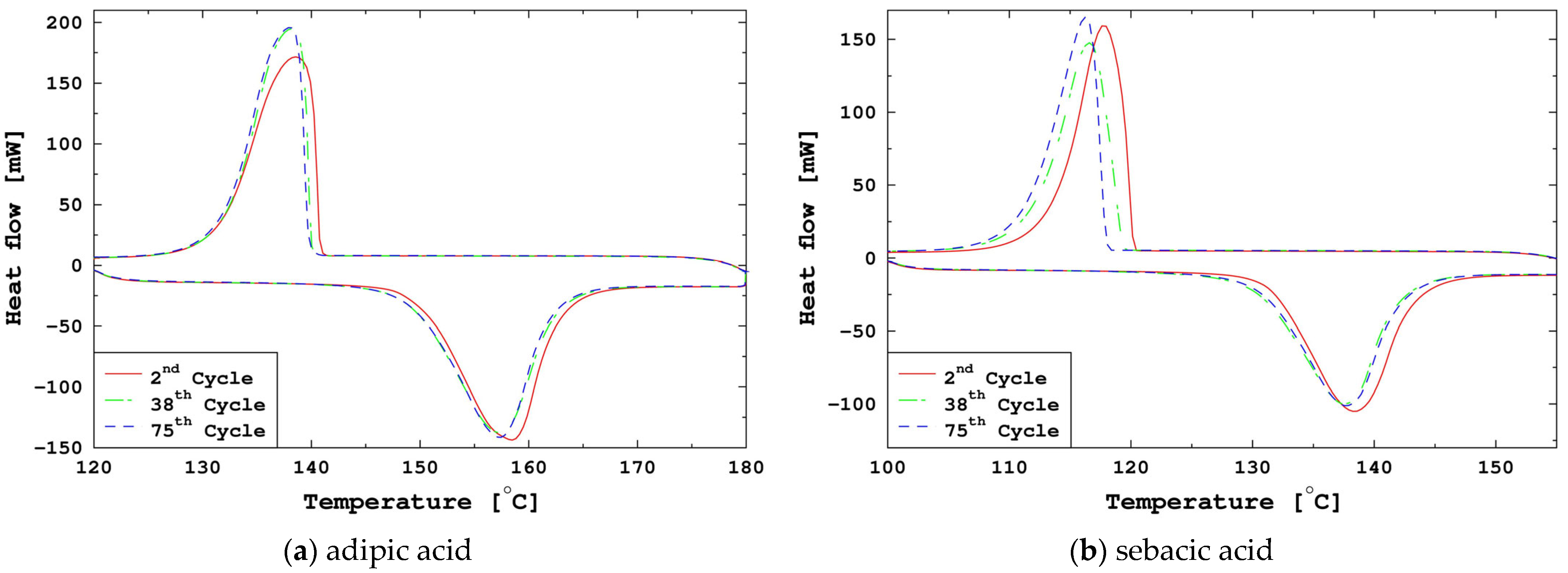
2.3.2. Results and Analysis
3. Stability and Corrosion Study
3.1. Materials and Method
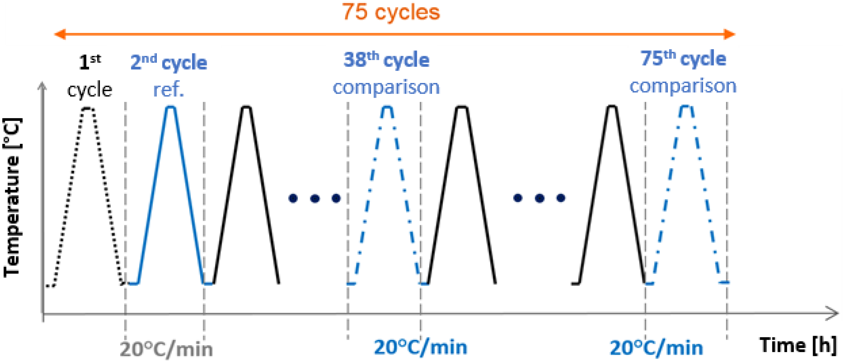
3.1.1. Stability Study: PCM Thermal Aging
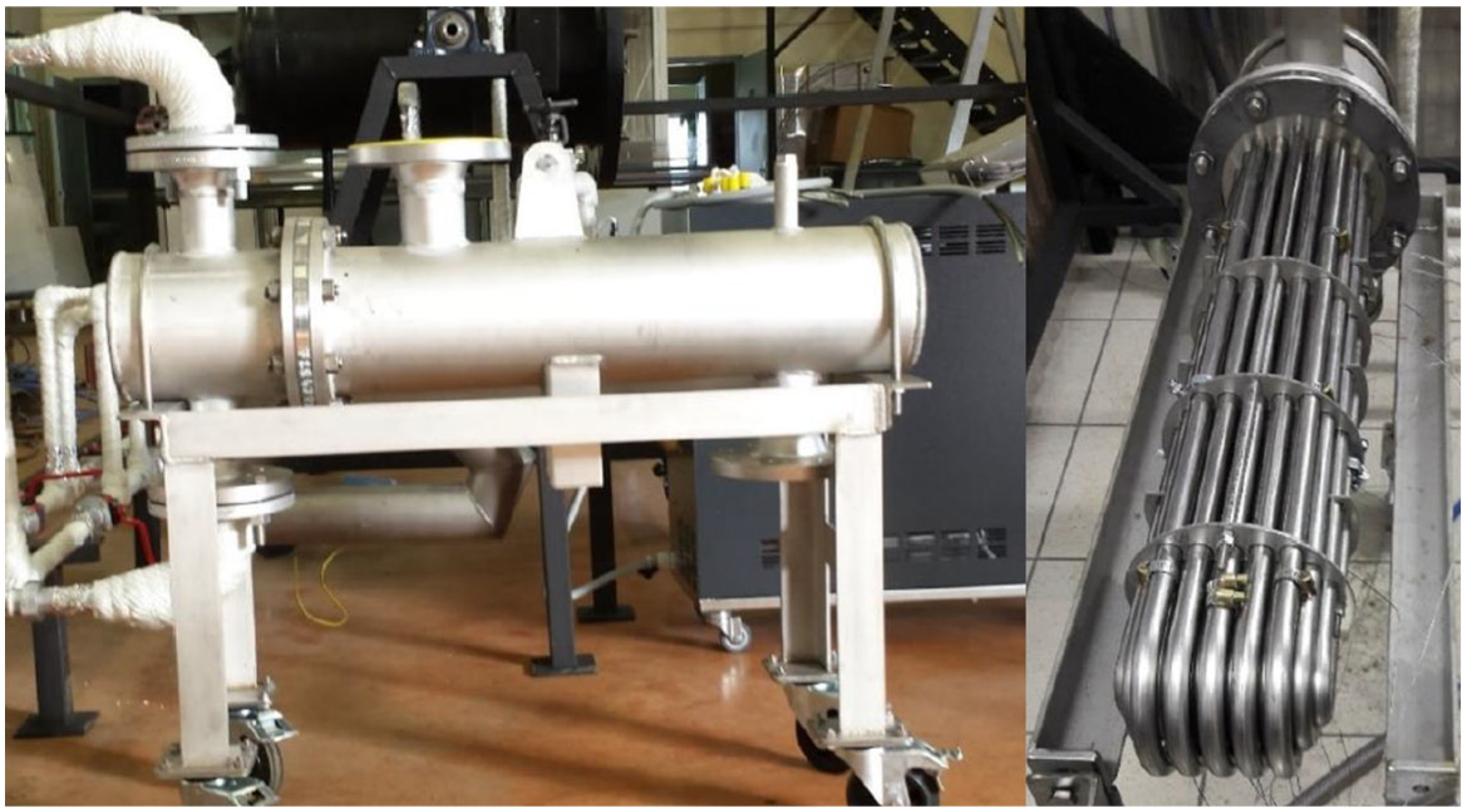
3.1.2. Corrosion Study: PCM and Envelope Thermal Aging
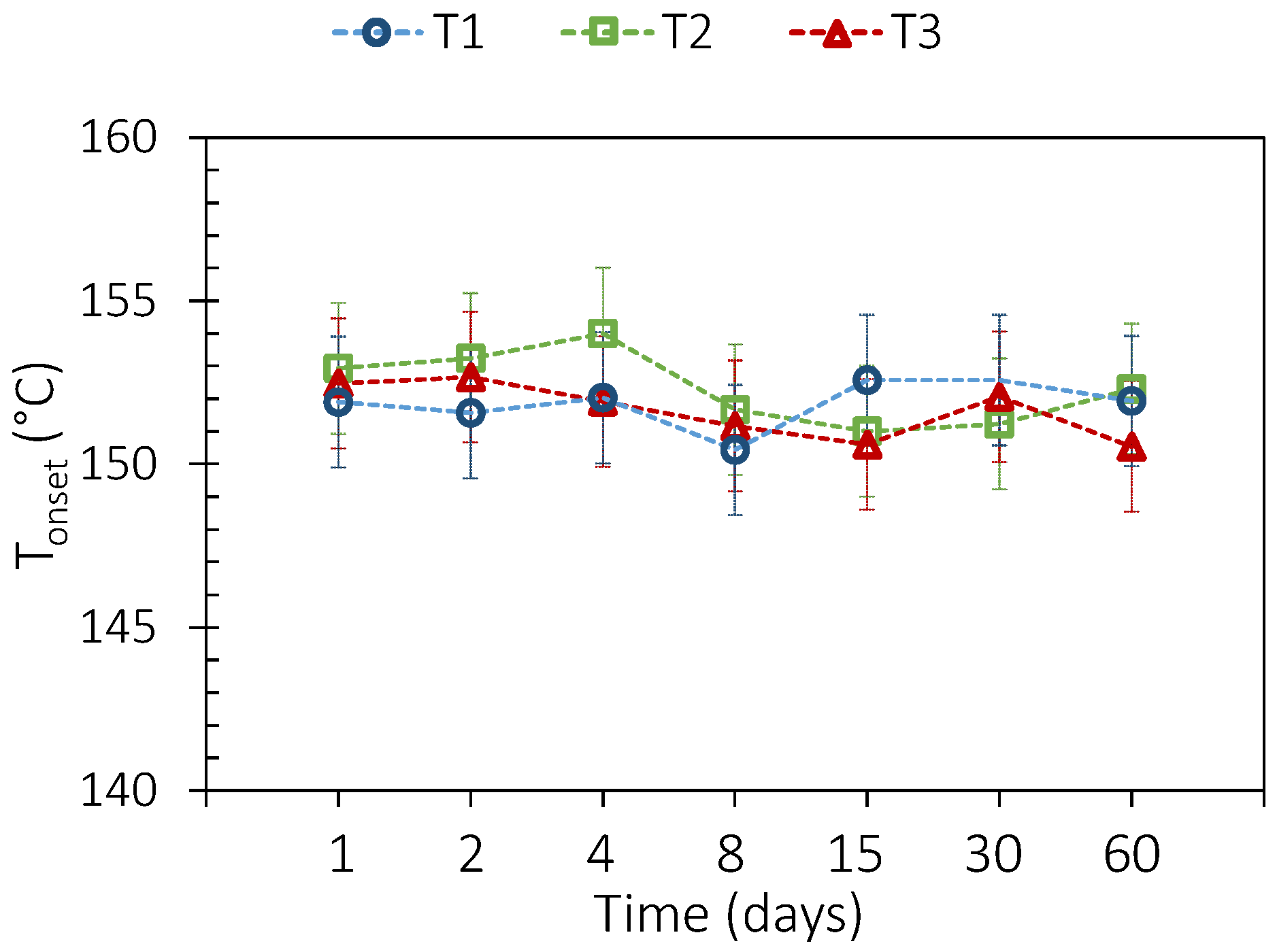
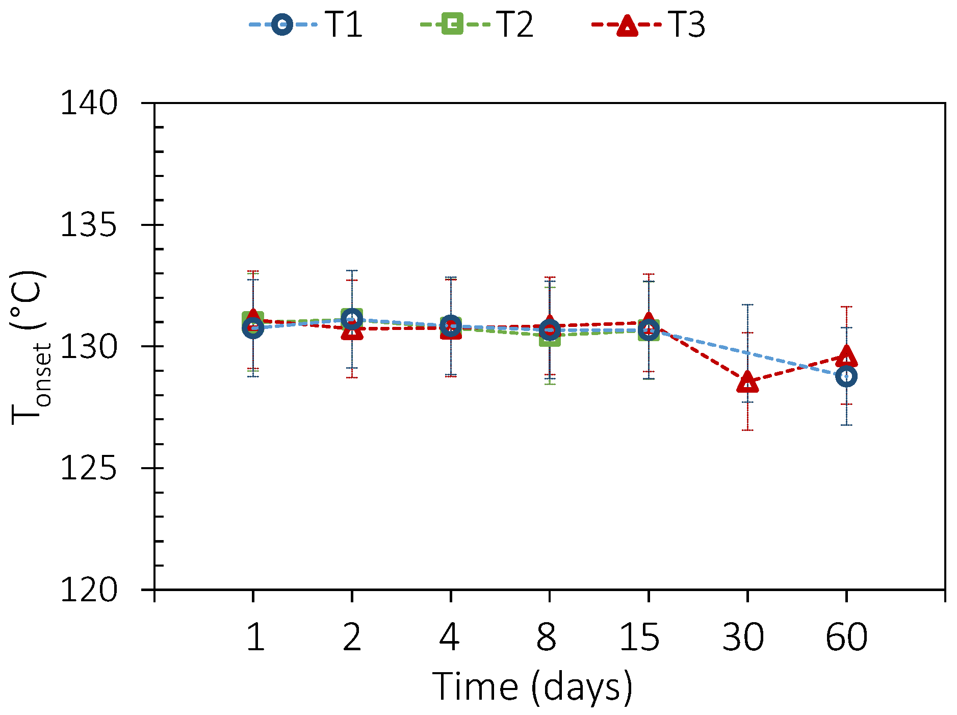
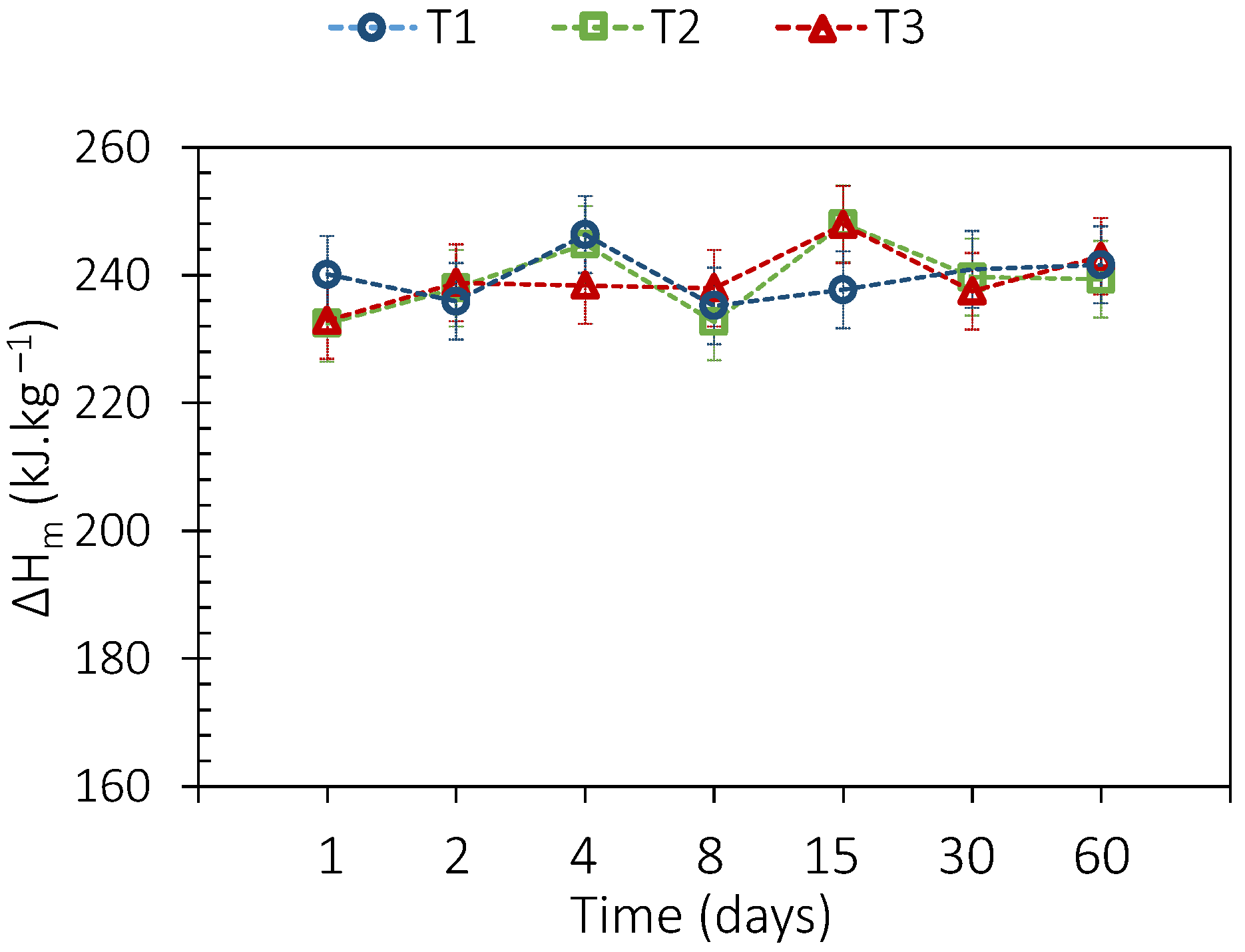
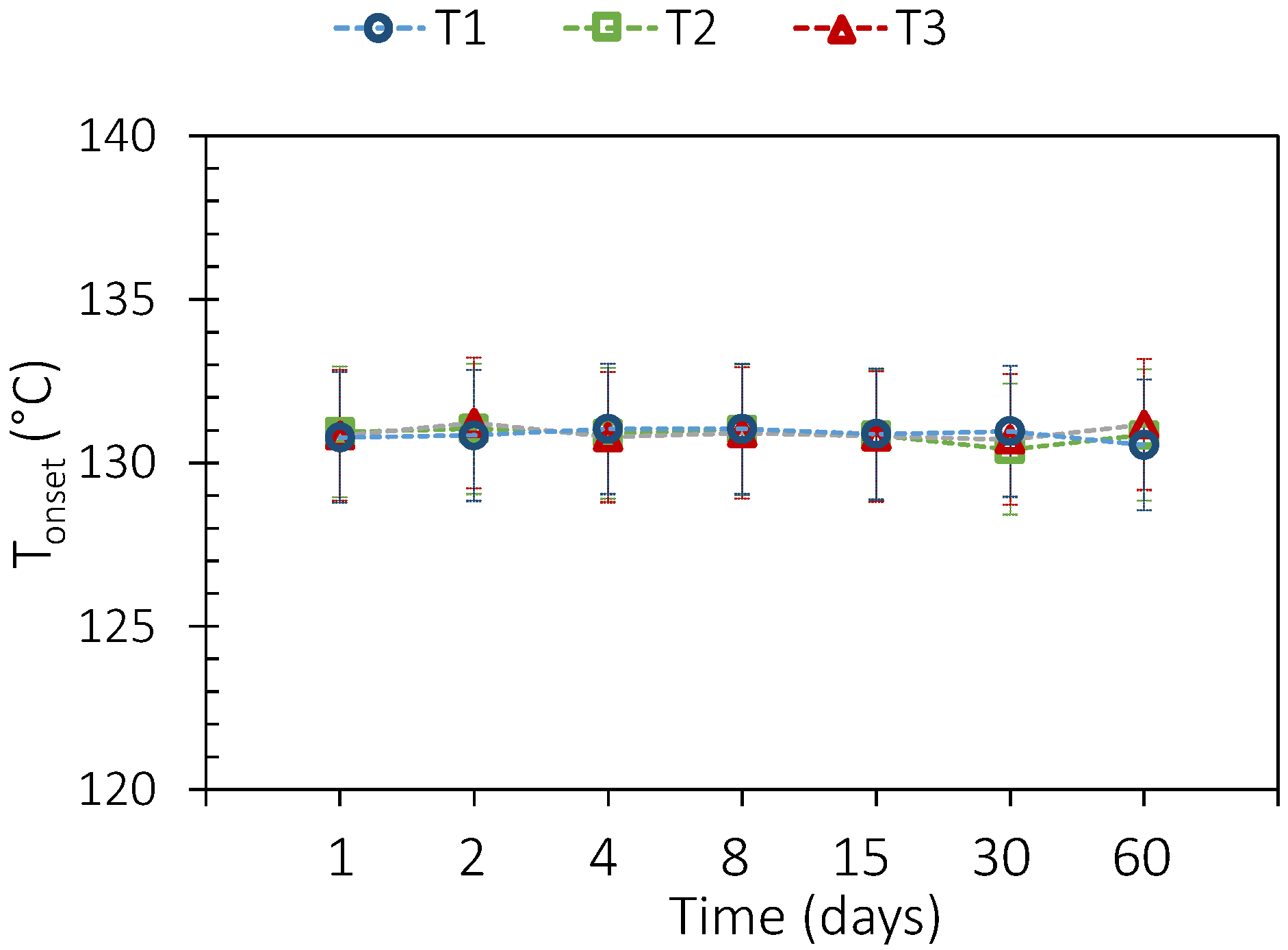
3.2. PCM Thermal Aging
3.3. PCM and Envelope Thermal Aging
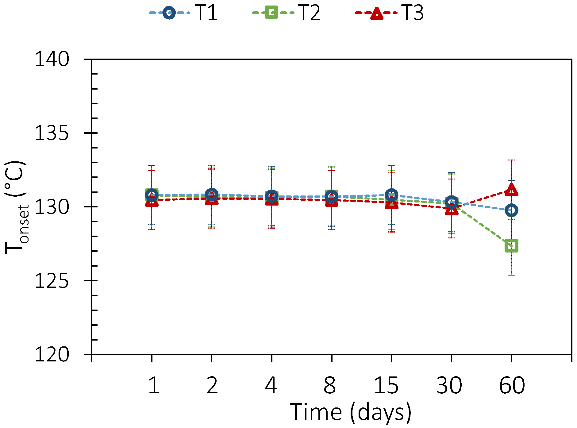
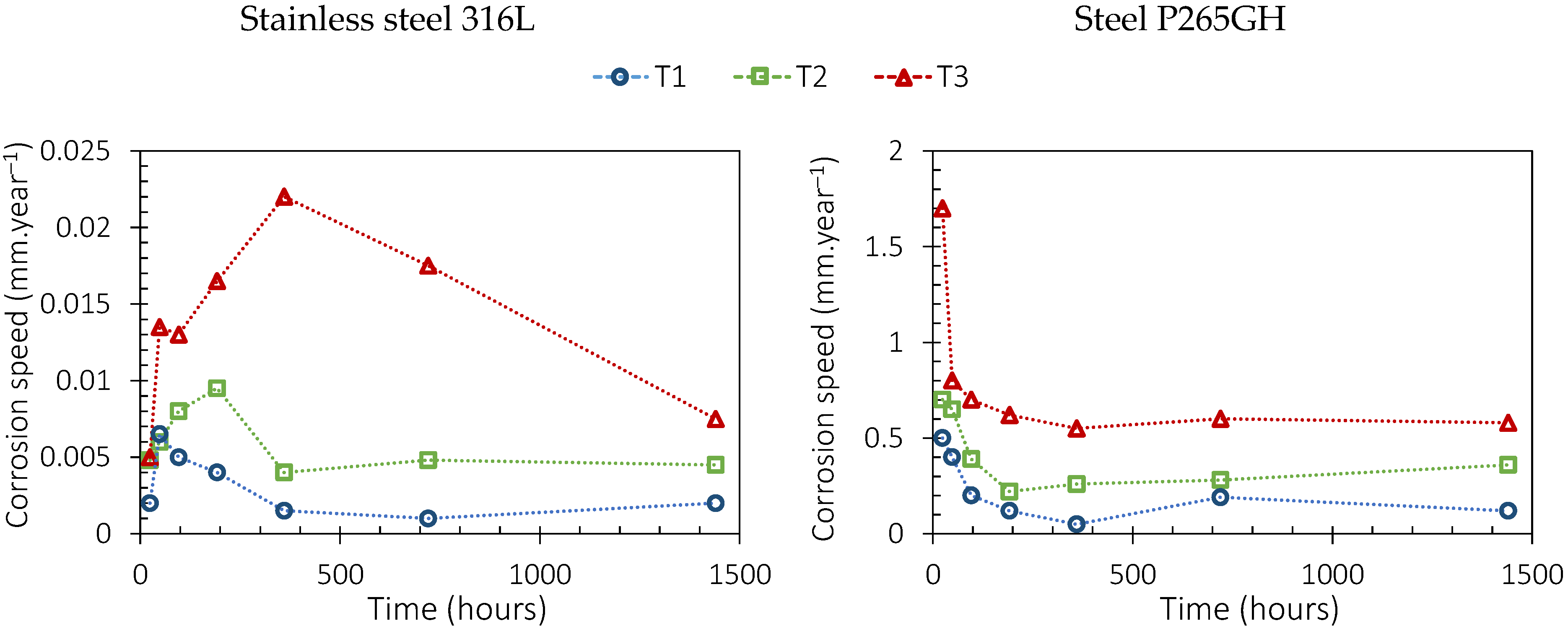
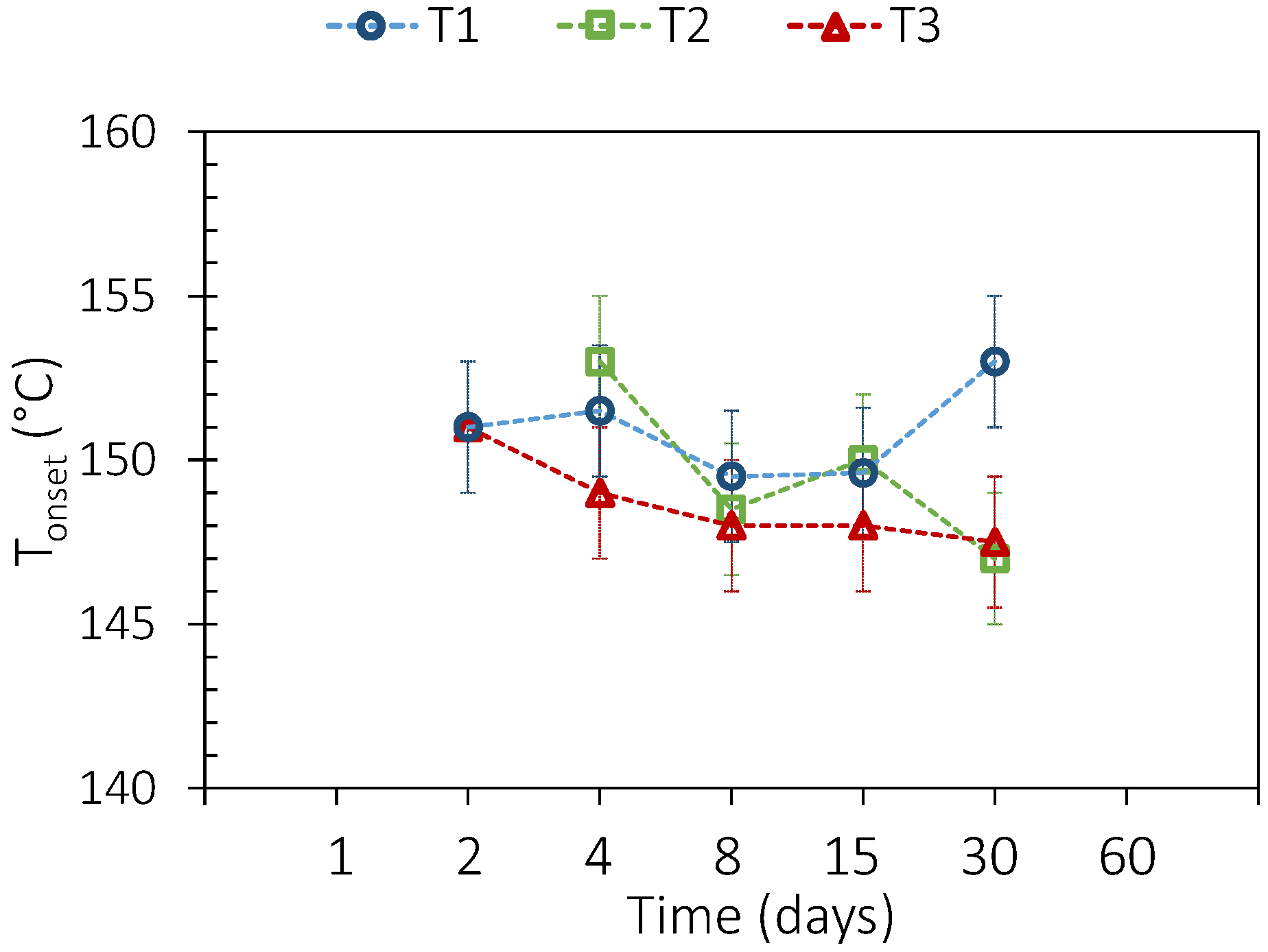
3.3.1. Sebacic Acid
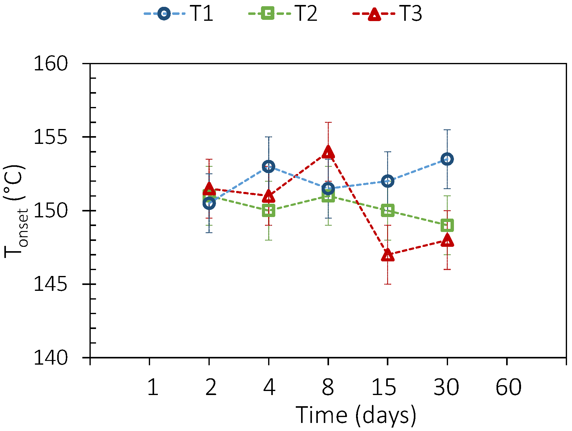
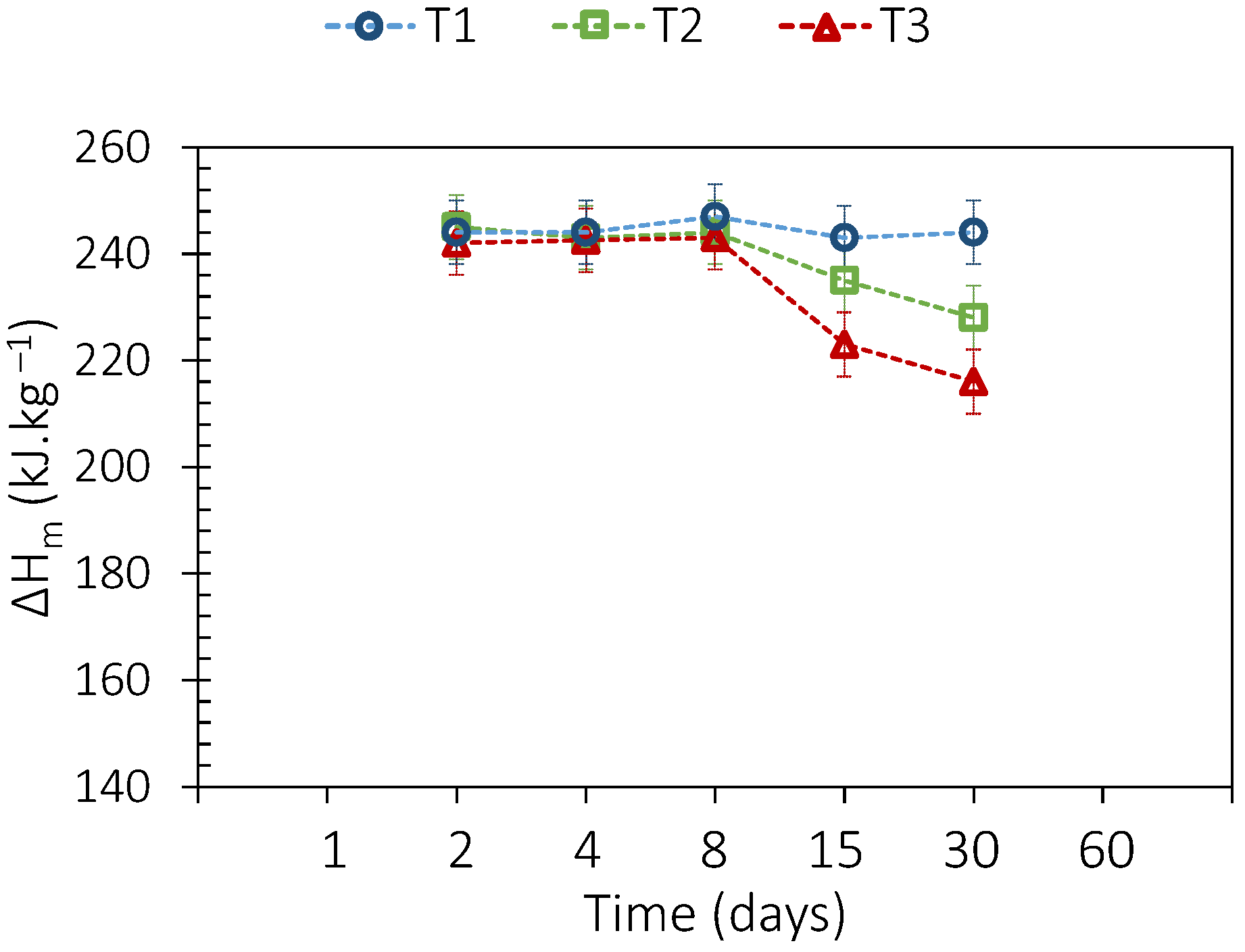
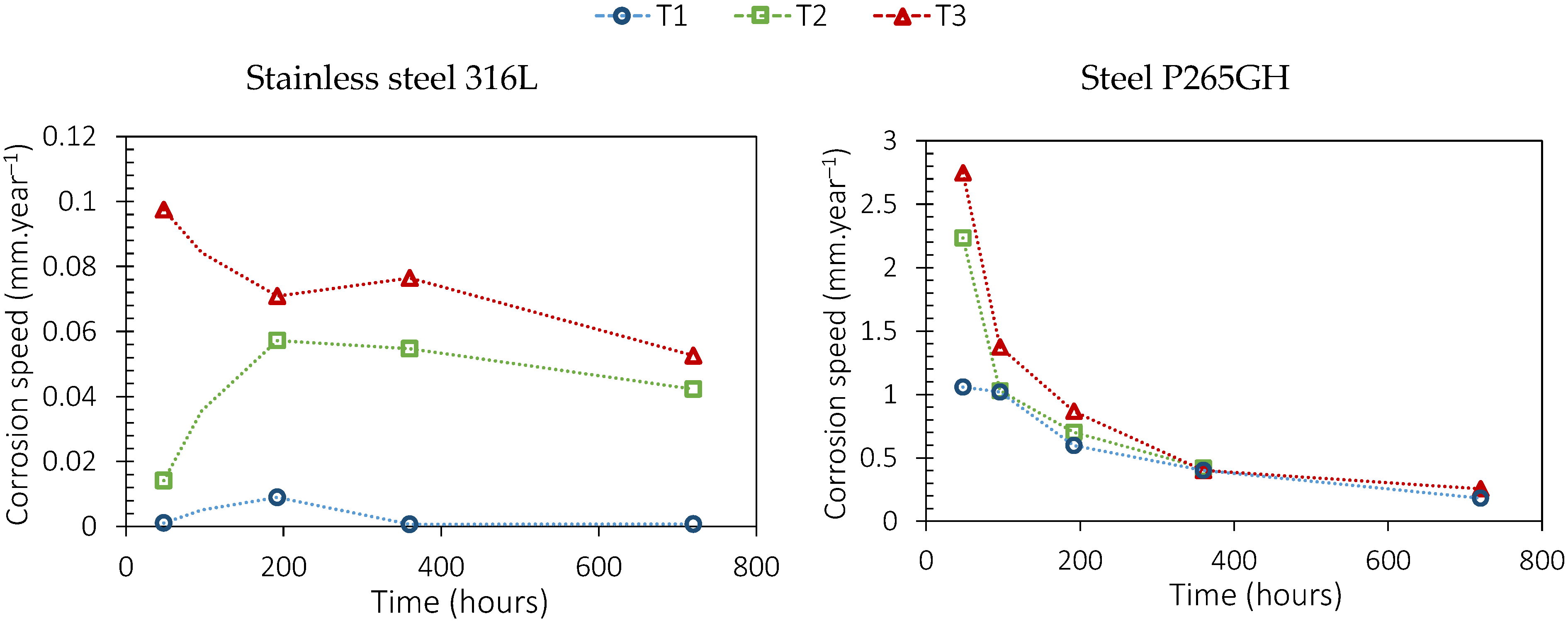
3.3.2. Adipic Acid
4. Conclusions
Author Contributions
Funding
Data Availability Statement
Conflicts of Interest
References
- ADEME. Chaleur Fatale, La Librairie ADEME. 2017. Available online: https://librairie.ademe.fr/energies-renouvelables-reseaux-et-stockage/2312-chaleur-fatale-9791029708954.html (accessed on 2 September 2023).
- Papapetrou, M.; Kosmadakis, G.; Cipollina, A.; La Commare, U.; Micale, G. Industrial waste heat: Estimation of the technically available resource in the EU per industrial sector, temperature level and country. Appl. Therm. Eng. 2018, 138, 207–216. [Google Scholar] [CrossRef]
- Johnson, I.; Choate, W.T.; Davidson, A. Waste Heat Recovery. Technology and Opportunities in U.S. Industry; US Department of Energy: Washington, DC, USA, 2008. [Google Scholar] [CrossRef]
- López-Sabirón, A.M.; Aranda-Usón, A.; Ferreira, V.J.; Ferreira, G. Environmental profile of latent energy storage materials applied to industrial systems. Sci. Total Environ. 2014, 473–474, 565–575. [Google Scholar] [CrossRef]
- Daniarta, S.; Nemś, M.; Kolasiński, P. A review on thermal energy storage applicable for low- and medium-temperature organic Rankine cycle. Energy 2023, 278, 127931. [Google Scholar] [CrossRef]
- Zalba, B.; Marin, J.; Cabeza, L.F.; Mehling, H. Review on thermal energy storage with phase change: Materials, heat transfer analysis and applications. Appl. Therm. Eng. 2003, 23, 251–283. [Google Scholar] [CrossRef]
- Abhat, A. Low temperature latent heat thermal energy storage: Heat storage materials. Sol. Energy 1983, 30, 313–332. [Google Scholar] [CrossRef]
- Sharma, R.K.; Ganesan, P.; Tyagi, V.V.; Metselaar, H.S.C.; Sandaran, S.C. Developments in organic solid–liquid phase change materials and their applications in thermal energy storage. Energy Convers. Manag. 2015, 95, 193–228. [Google Scholar] [CrossRef]
- Gunasekara, S.N.; Pan, R.; Chiu, J.N.; Martin, V. Polyols as phase change materials for surplus thermal energy storage. Appl. Energy 2016, 162, 1439–1452. [Google Scholar] [CrossRef]
- Beaupere, N.; Soupremanien, U.; Zalewski, L. Nucleation triggering methods in supercooled phase change materials (PCM), a review. Thermochim. Acta 2018, 670, 184–201. [Google Scholar] [CrossRef]
- Lin, Y.; Jia, Y.; Alva, G.; Fang, G. Review on thermal conductivity enhancement, thermal properties and applications of phase change materials in thermal energy storage. Renew. Sustain. Energy Rev. 2018, 82, 2730–2742. [Google Scholar] [CrossRef]
- Vasu, A.; Hagos, F.Y.; Noor, M.M.; Mamat, R.; Azmi, W.H.; Abdullah, A.A.; Ibrahim, T.K. Corrosion effect of phase change materials in solar thermal energy storage application. Renew. Sustain. Energy Rev. 2017, 76, 19–33. [Google Scholar] [CrossRef]
- Krishna, D.J.; Shinde, A. Step by Step Methodology for the Assessment of Metal Corrosion Rate with PCMs Suitable for Low Temperature Heat Storage Applications. Mater. Today Proc. 2017, 4, 10039–10042. [Google Scholar] [CrossRef]
- Moreno, P.; Miró, L.; Solé, A.; Barreneche, C.; Solé, C.; Martorell, I.; Cabeza, L.F. Corrosion of metal and metal alloy containers in contact with phase change materials (PCM) for potential heating and cooling applications. Appl. Energy 2014, 125, 238–245. [Google Scholar] [CrossRef]
- Oró, E.; Miró, L.; Barreneche, C.; Martorell, I.; Farid, M.M.; Cabeza, L.F. Corrosion of metal and polymer containers for use in PCM cold storage. Appl. Energy 2013, 109, 449–453. [Google Scholar] [CrossRef]
- Yin, Y.; Rumman, R.; Chambers, B.A.; Liu, M.; Jacob, R.; Belusko, M.; Bruno, F.; Lewis, D.A.; Andersson, G.G. Corrosion interface formation in thermally cycled stainless steel 316 with high-temperature phase change material. Sol. Energy Mater. Sol. Cells 2021, 225, 111062. [Google Scholar] [CrossRef]
- Delise, T.; Tizzoni, A.C.; Ferrara, M.; Corsaro, N.; D’Ottavi, C.; Sau, S.; Licoccia, S. Thermophysical, environmental, and compatibility properties of nitrate and nitrite containing molten salts for medium temperature CSP applications: A critical review. J. Eur. Ceram. Soc. 2019, 39, 92–99. [Google Scholar] [CrossRef]
- Opolot, M.; Zhao, C.; Liu, M.; Mancin, S.; Bruno, F.; Hooman, K. A review of high temperature (≥500 °C) latent heat thermal energy storage. Renew. Sustain. Energy Rev. 2022, 160, 112293. [Google Scholar] [CrossRef]
- Zhou, C.; Wu, S. Medium- and high-temperature latent heat thermal energy storage: Material database, system review, and corrosivity assessment. Int. J. Energy Res. 2018, 43, 621–661. [Google Scholar] [CrossRef]
- Devanuri, J.K.; Gaddala, U.M.; Kumar, V. Investigation on compatibility and thermal reliability of phase change materials for low-temperature thermal energy storage. Mater. Renew. Sustain. Energy 2020, 9, 24. [Google Scholar] [CrossRef]
- Ferrer, G.; Solé, A.; Barreneche, C.; Martorell, I.; Cabeza, L.F. Corrosion of metal containers for use in PCM energy storage. Renew. Energy 2015, 76, 465–469. [Google Scholar] [CrossRef]
- Kahwaji, S.; Johnson, M.B.; Kheirabadi, A.C.; Groulx, D.; White, M.A. Fatty acids and related phase change materials for reliable thermal energy storage at moderate temperatures. Sol. Energy Mater. Sol. Cells 2017, 167, 109–120. [Google Scholar] [CrossRef]
- Hua, W.; Xu, X.; Zhang, X.; Yan, H.; Zhang, J. Progress in corrosion and anti-corrosion measures of phase change materials in thermal storage and management systems. J. Energy Storage 2022, 56, 105883. [Google Scholar] [CrossRef]
- Calabrese, L.; Brancato, V.; Paolomba, V.; Proverbio, E. An experimental study on the corrosion sensitivity of metal alloys for usage in PCM thermal energy storages. Renew. Energy 2019, 138, 1018–1027. [Google Scholar] [CrossRef]
- Mohamed, S.A.; Al-Sulaiman, F.A.; Ibrahim, N.I.; Zahir, M.H.; Al-Ahmed, A.; Saidur, R.; Yılbaş, B.S.; Sahin, A.Z. A review on current status and challenges of inorganic phase change materials for thermal energy storage systems. Renew. Sustain. Energy Rev. 2017, 70, 1072–1089. [Google Scholar] [CrossRef]
- Sharma, A.; Tyagi, V.V.; Chen, C.R.; Buddhi, D. Review on thermal energy storage with phase change materials and applications. Renew. Sustain. Energy Rev. 2009, 13, 318–345. [Google Scholar] [CrossRef]
- Hauer, A. Thermal Energy Storage, Technology Brief, ETSAP, IRENA. 2013. Available online: https://www.irena.org/-/media/Files/IRENA/Agency/Publication/2013/IRENA-ETSAP-Tech-Brief-E17-Thermal-Energy-Storage.pdf (accessed on 1 September 2023).
- Espagnet, A.R. Techno-Economic Assessment of Thermal Energy Storage Integration into Low Temperature District Heating Networks. Master’s Thesis, KTH School of Industrial Engineering and Management, Stockholm, Sweden, 2016. [Google Scholar]
- Lalau, Y.; Haillot, D.; Rigal, S.; Bedecarrats, J.-P. Stockage Thermique Latent Pour la Récupération de Chaleur Fatale (120–150 °C): Stabilité des Matériaux. In Annales du Congrès Annuel de la Société Française de Thermique 2020; Tome 1; Societe Francaise de Thermique: Strasbourg, France, 2020; pp. 145–152. [Google Scholar]
- Jankowski, N.R.; Mccluskey, F.P. A review of phase change materials for vehicle component thermal buffering. Appl. Energy 2014, 113, 1525–1561. [Google Scholar] [CrossRef]
- Waschull, J.; Müller, R.; Römer, S. Investigation of Phase Change Materials for Elevated Temperatures; Dresden, Germany. 2009. Available online: https://www.researchgate.net/publication/309045719_Investigation_of_phase_change_materials_for_elevated_temperatures (accessed on 4 September 2023).
- Sharma, S.D.; Sagara, K. Latent Heat Storage Materials and Systems: A Review. Int. J. Green Energy 2005, 2, 1–56. [Google Scholar] [CrossRef]
- Haillot, D.; Bauer, T.; Kröner, U.; Tamme, R. Thermal analysis of phase change materials in the temperature range 120–150 °C. Thermochim. Acta 2011, 513, 49–59. [Google Scholar] [CrossRef]
- Sharma, S.D.; Kitano, H.; Sagara, K. Phase Change Materials for Low Temperature Solar Thermal Applications. Res. Rep. Fac. Eng. Mie Univ. 2004, 29, 31–64. [Google Scholar]
- Nazir, H.; Batool, M.; Osorio, F.J.B.; Isaza-Ruiz, M.; Xu, X.; Vignarooban, K.; Phelan, P.; Kannan, A.M. Recent developments in phase change materials for energy storage applications: A review. Int. J. Heat Mass Transf. 2019, 129, 491–523. [Google Scholar] [CrossRef]
- Dumas, J.-P. Etude de la Rupture de Métastabilité et du Polymorphisme de Corps Organiques. Ph.D. Thesis, Université de Pau, Pau, France, 1976. [Google Scholar]
- Kouadio, T.; Sommier, A. Characterization of different sugar alcohols as phase change materials for thermal energy storage applications. Sol. Energy Mater. Sol. Cells 2017, 159, 560–569. [Google Scholar]
- Da Cunha, J.P.; Eames, P. Thermal energy storage for low and medium temperature applications using phase change materials–A review. Appl. Energy 2016, 177, 227–238. [Google Scholar] [CrossRef]
- Huang, Z.; Xie, N.; Luo, Z.; Gao, X.; Fang, X.; Fang, Y. Characterization of medium-temperature phase change materials for solar thermal energy storage using temperature history method. Sol. Energy Mater. Sol. Cells 2018, 179, 152–160. [Google Scholar] [CrossRef]
- Tan, P.; Brütting, M.; Vidi, S.; Ebert, H.-P.; Johansson, P.; Kalagasidis, A.S. Characterizing phase change materials using the T-History method: On the factors influencing the accuracy and precision of the enthalpy-temperature curve. Thermochim. Acta 2018, 666, 212–228. [Google Scholar] [CrossRef]
- Gibout, S.; Franquet, E.; Haillot, D.; Bédécarrats, J.-P.; Dumas, J.-P. Challenges of the usual graphical methods used to characterize Phase Change Materials by Differential Scanning Calorimetry. Appl. Sci. 2018, 8, 66. [Google Scholar] [CrossRef]
- ASTM G1-03(2017)e1; Standard Practice for Preparing, Cleaning, and Evaluating Corrosion Test Specimens. ASTM International: West Conshohocken, PA, USA, 2017. [CrossRef]
- Davis, J.R. Corrosion: Understanding the Basics; ASM International: West Conshohocken, PA, USA, 2000. [Google Scholar]


| DSC (2nd, 38th, and 75th Cycles) | TGA | |||||||
|---|---|---|---|---|---|---|---|---|
| Tonset [°C] | ΔHm, vol [kWh·m−3] | ΔTmean [°C] | T1% [°C] | |||||
| Precision | ±0.4 °C | ±1.3% | ±0.4 °C | - | ||||
| Succinic anhydride | 115.3 | 115.7 | 115.3 | 77.6 | 74.5 | 71.9 | 60.8 | 115.7 |
| Benzoïque acid | 121.5 | 120.5 | 120.7 | 49.6 | 47.1 | 46.4 | 25.0 | 122.4 |
| Phtalic anhydride | 129.1 | 128.9 | 129 | 65.9 | 60.4 | 58.7 | 27.3 | 124.0 |
| Sebacic acid | 131.5 | 130.3 | 130.8 | 75 | 70 | 71 | 11.7 | 181.0 |
| Dimethyl terephtalate | 140.2 | 139.9 | 140.4 | 58.4 | 54.8 | 53.4 | 9.7 | 128.7 |
| Adipic acid | 150.0 | 149.1 | 149.6 | 95.2 | 92.6 | 92.2 | 10.0 | 186.1 |
| Corrosion Speed [mm·Year−1] | Recommendations |
|---|---|
| >2 | Completely ruined in a few days |
| 0.2–2 | Not recommended for use longer than one month |
| 0.1–0.2 | Not recommended for use longer than one year |
| 0.02–0.1 | Use carefully depending on conditions |
| <0.02 | Long-term use |
Disclaimer/Publisher’s Note: The statements, opinions and data contained in all publications are solely those of the individual author(s) and contributor(s) and not of MDPI and/or the editor(s). MDPI and/or the editor(s) disclaim responsibility for any injury to people or property resulting from any ideas, methods, instructions or products referred to in the content. |
© 2024 by the authors. Licensee MDPI, Basel, Switzerland. This article is an open access article distributed under the terms and conditions of the Creative Commons Attribution (CC BY) license (https://creativecommons.org/licenses/by/4.0/).
Share and Cite
Lalau, Y.; Rigal, S.; Bédécarrats, J.-P.; Haillot, D. Latent Thermal Energy Storage System for Heat Recovery between 120 and 150 °C: Material Stability and Corrosion. Energies 2024, 17, 787. https://doi.org/10.3390/en17040787
Lalau Y, Rigal S, Bédécarrats J-P, Haillot D. Latent Thermal Energy Storage System for Heat Recovery between 120 and 150 °C: Material Stability and Corrosion. Energies. 2024; 17(4):787. https://doi.org/10.3390/en17040787
Chicago/Turabian StyleLalau, Yasmine, Sacha Rigal, Jean-Pierre Bédécarrats, and Didier Haillot. 2024. "Latent Thermal Energy Storage System for Heat Recovery between 120 and 150 °C: Material Stability and Corrosion" Energies 17, no. 4: 787. https://doi.org/10.3390/en17040787
APA StyleLalau, Y., Rigal, S., Bédécarrats, J.-P., & Haillot, D. (2024). Latent Thermal Energy Storage System for Heat Recovery between 120 and 150 °C: Material Stability and Corrosion. Energies, 17(4), 787. https://doi.org/10.3390/en17040787