Abstract
The introduction of distributed generation (DG) into distribution systems is expanding due to carbon neutral policies. DG with intermittent output characteristics brings frequent voltage variations in distribution systems. Generally, a step voltage regulator (SVR) is installed in the long distribution line and controls its voltage, which has limits of stable voltage regulations due to the slow tap-changing rate, switching losses, and short life span. To solve those problems, this paper proposes an IGBT-based SVR using zero-voltage switching. It is verified that the stable operation can be obtained through simulation by PSCAD/EMTDC 4.6 software and empirical experiments.
1. Introduction
With carbon neutral policies around the world, the introduction of distributed generation (DG), such as solar power generation, into distribution systems is expanding. In particular, when distribution lines are long, voltage variations become more pronounced due to the intermittent output of DG. This has a negative impact on the power quality of consumers.
A countermeasure against this voltage variation is to install a voltage controller called a step voltage regulator (SVR) in the middle of a long distribution line to adjust the voltage to an appropriate range [1,2].
An SVR usually uses mechanical switches to move taps, which may cause contact wear and arcing and are unfavorable for frequent operations [3,4,5]. Additionally, the slow tap-changing rate with a time delay during tap changes may expose loads in distribution lines to under- or overvoltage.
To solve those problems, hybrid and power semiconductor methods have been proposed. The hybrid method uses both mechanical contacts and power semiconductors for tap changing, which enables relatively fast switching. However, if a proper procedure is not performed during the tap-changing process, arcing may occur, causing carbonization of the contacts and requiring constant maintenance [6,7,8,9].
Therefore, it is necessary to design an SVR using a power semiconductor with fast tap changing and no arcing. Power semiconductors include a thyristor, TRIAC, and an insulated gate bipolar transistor (IGBT). The SVR using a thyristor, named a thyristor voltage regulator (TVR), has been developed and applied to long distribution lines until now because it has relatively high power and high voltage ratings compared to other devices [10,11].
However, a thyristor is a line-commuted device, and a short circuit occurs when switching taps around the current zero point [12,13,14]. To prevent the large current in short circuit, a resistor or inductor is used [15,16,17,18], but the slow switching rate of a thyristor and the control complexity still remain challenges. TRIAC with two thyristors connected in anti-parallel also has the same problem [19]. On the other hand, IGBT has not been used as switch elements in an SVR due to low blocking voltage. Nevertheless, IGBT is replacing conventional thyristors because it operates at high speeds with self-commutation and is useful for continuous voltage regulation [20,21,22,23].
Power semiconductors have characteristics such as latching current and threshold voltage that cause a time delay between turning on and off. Therefore, these require inductors to be connected in series with the switching device for continuous current flow [21]. However, it increases switching stress and losses in bidirectional commutation. In addition, a short circuit may occur during instantaneous tap hard changing. The turn-on/off overlap switching between switches during tap changes is applied in an SVR [22]. This has the advantage of avoiding the interruption of the current but comes with the disadvantage of large switching losses and a short-circuit current when controlling high voltage and large power. In an SVR using IGBT, a short-circuit current and circulating current may occur when two switches are turned on and off simultaneously due to an error signal by the power supply [24,25].
To enhance the stability and efficiency of the IGBT-based SVR (ISVR), the zero-current switching method is used as a control scheme for bidirectional IGBTs. This method offers the advantage of reducing voltage surges that occur during tap changes and minimizing switching losses [26,27]. In this method, commutation is based on the current direction. Thus, if it changes during the commutation process, a short current may occur and may cause damage to the switching elements. Also, the phase difference between the voltage and current in inductive loads may push the collector–emitter voltage () beyond its voltage rated at the current zero point, resulting in inaccurate switching operations.
Zero-voltage switching is performed around the voltage zero-point and the short-circuit current is quite small. Therefore, the zero-voltage switching can ensure the stable switching operation of the IGBT and reliably eliminate switching losses [28,29].
This paper proposes a new ISVR which has an SVR topology to minimize the occurrence of overvoltage causing a short current, and the zero-voltage switching method is applied for safe and easy control.
Section 2 describes the general SVR’s switching methods and their problems. In Section 3, its topology and switching method is proposed. In Section 4, a simulation is conducted by modeling the target distribution system and ISVR using PSCAD. In Section 5, the empirical experiment is conducted to confirm the performance through building the ISVR.
2. Classification of an SVR
An SVR can be categorized into mechanical, hybrid, and electronic switching methods based on the type of switching device. This chapter provides a description of the control process and associated challenges.
2.1. Mechanical SVR
According to the IEC 60076-21 [30] standard, a mechanical SVR is divided into series winding and series transformer, both with an A type or B type, depending on the location of the series winding or transformer.
2.1.1. Series Winding SVR
Figure 1 shows the A-type series winding SVR which has a series winding and a shunt winding. In addition, the current transformer and voltage transformer are connected for measuring the load current and load-side voltage, respectively. The series winding adjusts by adjusting its tap. In the B-type series winding, its series winding is on the opposite side to that of type A.
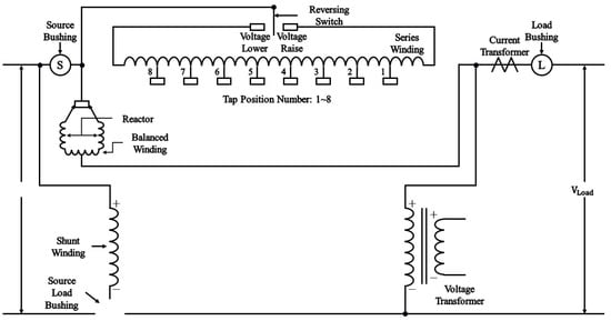
Figure 1.
A-type series winding SVR.
2.1.2. Series Transformer SVR
As shown in Figure 2, the series winding in Figure 1 is replaced by a series transformer which is connected to the secondary winding of the parallel transformer. This has type A and B according to its series transformer location.
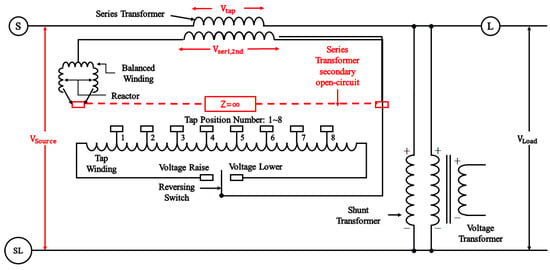
Figure 2.
A-type series transformer SVR.
In the case of the series transformer, caution must be exercised, as overvoltage may occur when switching taps due to the opening of the secondary side of the series transformer, as illustrated in Figure 2.
2.2. Hybrid SVR
The hybrid SVR uses a combination of mechanical switches and power semiconductors to reduce arcing associated with tap switching.
2.2.1. Thyristor Type
A hybrid SVR using a thyristor is shown as Figure 3. It incorporates a diverter switch structure to enhance arc extinction, resulting in a relatively faster tap-changing speed compared to a mechanical SVR [6].
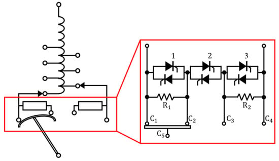
Figure 3.
Hybrid SVR using a thyristor.
This method offers the advantage of significantly reducing arcing. During the tap-changing process, the anti-parallel connected thyristors ignite for a short period of time. However, thyristors have the disadvantage that the holding current may lead to short circuits between taps, thereby reducing the reliability of the system.
2.2.2. IGBT Type
Figure 4 shows a hybrid SVR using IGBTs, which are connected in series. There is no need for a current-limiting impedance between changing taps, enabling quick switching between taps. However, this method requires complex control when tap changing [9].
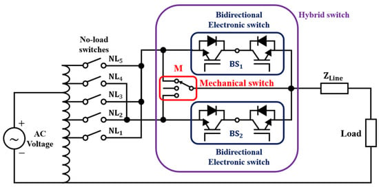
Figure 4.
Hybrid SVR using IGBT.
2.3. Power Semiconductor-Based SVR
2.3.1. Thyristor Type
Figure 5 shows a TVR which is three-terminal unidirectional and is connected by two devices in anti-parallel to enable the bidirectional flow of current in a TRIAC-like structure [16].
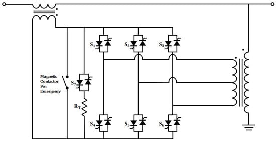
Figure 5.
TVR with current-limiting resistor.
This TVR has a current-limiting resistor (), six tap-changing switches (), and one bypass switch ().
The current-limiting resistance goes through a bypass circuit during tap changing. At that time, the bypass circuit consists of the secondary side of the series transformer and the resistance. In this process, a voltage drop occurs as much as the load current multiplied by the resistance value, also causing the same drop in the distribution line.
2.3.2. IGBT Type
Figure 6 shows the circuit of an IGBT-based SVR using zero-current switching [27], which uses capacitors to reduce the voltage surge that occurs during tap changing.
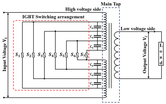
Figure 6.
IGBT-based SVR with zero-current switching.
Zero-current switching is performed at the zero-point of the current, ensuring the minimization of surge voltage during switching. However, in the event of a change in current direction or an error during tap changing, a short circuit may occur.
2.4. Comparison of SVR According to the Switching Method
A mechanical SVR has the advantage of low power losses in a steady state and high ratings. However, it has the disadvantage of shortening the life span due to the slow tap-switching speed and the occurrence of arcs during switching.
A hybrid SVR allows for relatively fast tap changing and can prevent arcing, but reliability may be reduced due to the complexity of auxiliary circuits and control.
A power semiconductor SVR has large power losses in a normal state. When tap changing, sufficient protection measures must be provided according to transient conditions and device capacity. Table 1 shows the pros and cons of different SVR methods.

Table 1.
Comparison of SVRs according to switching method.
3. A New ISVR
In this section, a new ISVR is introduced. It incorporates an SVR topology designed to minimize the occurrence of overvoltage, which can lead to short circuits. Additionally, zero-voltage switching is applied for safe and convenient control with inductive loads. Section 3.1 explains the structure and Section 3.2 covers the operating principle.
3.1. Topology of an ISVR
An ISVR uses the series transformer structure of IEC 60076-21, which has a tap on the load-side transformer and is considered optimal in terms of power rating and insulation requirements. The series transformer () for voltage compensation is located on the source side. A 4-winding parallel transformer () to determine the compensation voltage is connected to the load side.
There are nine switches (), and switching operations occur when the tap is changed. Among the nine switches, numbers are bidirectional IGBT switches which perform switching operations when tap changing. Once the compensation voltage is determined, two of the eight switches are selected and fired. There are total of 13 voltage levels that can be controlled through the fired switch and the secondary winding of the parallel transformer. serves as a bypass circuit and uses a relatively high rated thyristor. This is used as a protection circuit for the IGBT in the event of ISVR internal failure or a distribution line accident.
The RC snubber circuits are connected in parallel to ensure minimum voltage surge in switching elements when changing taps. The equivalent circuit of the tap-changing transformer is shown in Figure 7.
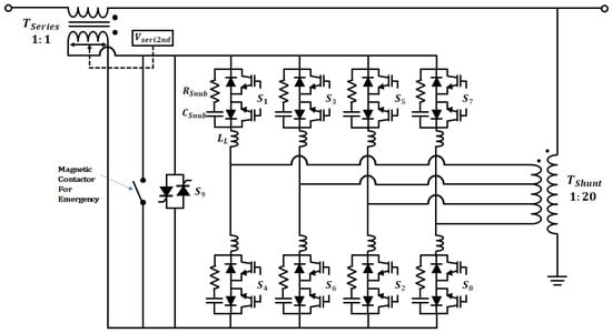
Figure 7.
Single-phase equivalent circuit for a new ISVR. , : series and shunt transformer. : secondary voltage of series transformer. : internal circuit inductance. ~: bidirectional IGBT module for tap changing. : bidirectional thyristor for bypass. , : snubber resistor and capacitor.
3.1.1. Design of Parallel Transformer Tap
This ISVR has ±δ% of the nominal voltage of the connected system as a compensation voltage, which has 13 taps. The unit tap voltage is determined by Equation (1). The compensation voltage and operation switches according to the tap position number are shown in Table 2.

Table 2.
Compensation voltage and operation switch according to tap position number.
A power semiconductor has a time delay between turning on and off. Therefore, a short circuit may occur due to a control error during the switching process of a power semiconductor, as shown in Figure 8. The short-circuit current is determined by tap position, and the short-circuit current is calculated by Equation (2).
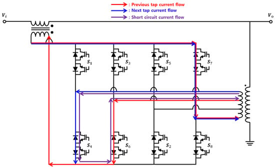
Figure 8.
Short-circuit current flow during short circuit in a new ISVR.
To minimize the magnitude of the short-circuit current, the voltage during tap changing must be set to the smallest value. Tap position numbering in Table 2 is proposed to satisfy that condition.
3.1.2. Bidirectional Switch Configuration
A bidirectional switch must take into account all of the characteristics of the device. Figure 9 shows bidirectional switches composed of a combination of power semiconductors.
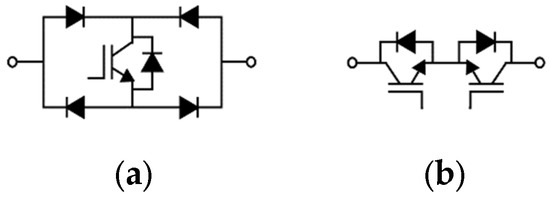
Figure 9.
Types of bidirectional switches: (a) 1 IGBT + 4 Diode; (b) 2 IGBT + 2 Diode.
Figure 9a is a bidirectional switch using an IGBT with a unidirectional flow in the middle of the full bridge composed of four diodes. Since it uses one IGBT, the structure is simple and the price is relatively low. However, the series operation of three power semiconductors for commutation results in high conduction losses and limited commutation control. Additionally, reliability is reduced because six control signals are required when switching taps. Figure 9b is a bidirectional switch consisting of two IGBTs and two diodes, with a common emitter arrangement. This arrangement allows for switching control in one time step through a common gate signal, thus reducing device control errors and increasing reliability. Therefore, the switch in the ISVR utilizes the arrangement shown in Figure 9b.
3.1.3. Voltage Regulator Method
The LDC method is used as a voltage control method. This method is applied to the SVR for proper voltage control of long distribution lines. It keeps the virtual load center point at a constant voltage to minimize voltage error regarding the voltage on the entire distribution line under load conditions from light load to peak load [31]. The virtual load center is also called the regulating point and its voltage is denoted by the symbol .
As shown in Figure 10, the LDC obtains the real-time voltage and current data measured by PT and CT at the secondary side of the SVR, which are denoted by and , respectively. The voltage of the regulating point with equivalent impedance can be calculated by Equation (3).
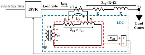
Figure 10.
Operation structure of LDC.
Then, according to whether is within the desired value , the ISVR’s tap operates up or down with a time delay.
Generally, and are determined by using the secondary side voltage of the SVR, and its power factor at peak load; or the secondary side voltage of the SVR and at a light load. They are calculated by Equation (2) for unidirectional power flow distribution systems without DG [31].
3.2. IGBT Switching Method
The IGBT’s switching method uses zero-voltage switching which enables simple control and minimizes switching losses. The reason for using zero-voltage switching is explained below.
In zero-point switching, there are usually two methods: zero-current switching and zero-voltage switching. First, zero-current switching is based on the amplitude and direction of the current. If the current direction changes between tap changes, a short circuit may occur. In addition, IGBTs can operate stably only when a switching signal is applied within a certain collector–emitter voltage range. However, most of the loads on distribution lines are inductive, which have a lagging power factor as shown in Figure 11. Due to the voltage–current phase difference in Figure 11, stable operation cannot be achieved if the switching signal is applied in a range beyond rated at the zero-point of the current.
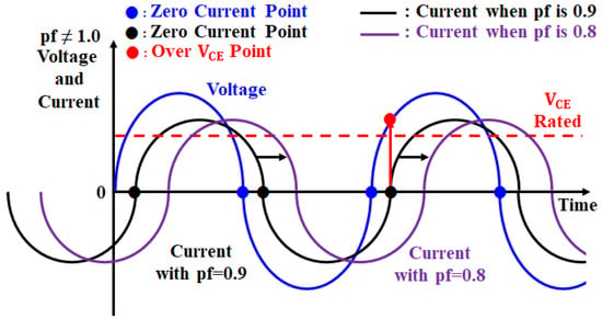
Figure 11.
Operation characteristic due to the voltage and current phase difference in inductive loads.
In Figure 11, the blue line represents the voltage wave, the black line the current wave when the load power factor is 0.9, and the purple line the current wave when the load power factor is 0.8. As the power factor decreases, the current has a phase angle that lags the voltage. In this paper, the magnitude of the current at the voltage zero-point is about 83 A and 103 A, respectively.
Zero-voltage switching can prevent overlap between the current and voltage by reducing the voltage to zero before the current begins to increase in switching-on transients. This can reduce switching and conduction losses by reducing voltage and current stress on the switching element.
Additionally, since the ISVR uses a bidirectional IGBT module, the operating characteristics of the device must be considered. After the voltage across the switch reaches zero, a turn-off delay occurs, as shown in Figure 12, owing to the IGBT characteristics and system clock time before switching to the next tap. If a tap is switched without considering the delay time and the IGBT corresponding to the next tap is fired, the parallel transformer and the IGBT form a short circuit, causing a large short-circuit current. In addition, the current temporarily flows into the snubber circuit of the switch during the delay time. If it is set too long, the series transformer may be open and the voltage across the series transformer becomes near to the system voltage 1.0 p.u. Therefore, zero-voltage switching through accurate zero-point detection is indispensable.
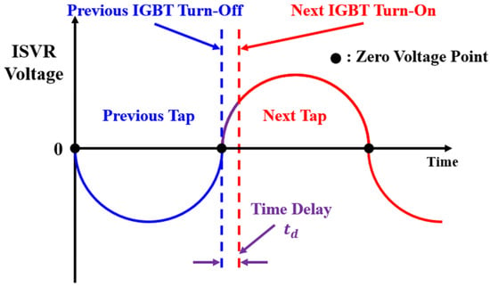
Figure 12.
Turn-off delay occurring during zero-voltage switching.
In addition to switching taps, the thyristor connected to the tap repeats turn-on and turn-off operations every half cycle for a bidirectional current flow. As a result, harmonic waves continuously occur [13,14]. On the other hand, IGBTs with a common emitter structure maintain conduction except for during tap switching, so harmonics do not occur. It is not easy to detect the zero point for voltages containing harmonics, but accurate zero-point detection is possible by reducing distortion using methods such as d-q transformation [32]. The voltage zero-point detector proposed in this paper is shown in Figure 13a. The zero-point detector measures the voltage of the ISVR circuit and generates the zero-voltage signal at the moment it crosses from “−V” to “+V” or vice versa based on amplitude 0. In Figure 13b, the zero-voltage signal has a value of 1 at the zero-voltage point, otherwise, it has 0 value.

Figure 13.
Voltage zero-point detection method: (a) voltage zero-point detection controller based on voltage amplitude; (b) zero-voltage signal depending on voltage amplitude.
The tap-switching procedure using zero-voltage switching is shown in Figure 14. If the line voltage is monitored and beyond a permissible voltage range, the tap-changing command is directed to the ISVR by the LDC. Then, tap change switching is performed at the nearest voltage zero-point just after a tap change command is directed to the ISVR.
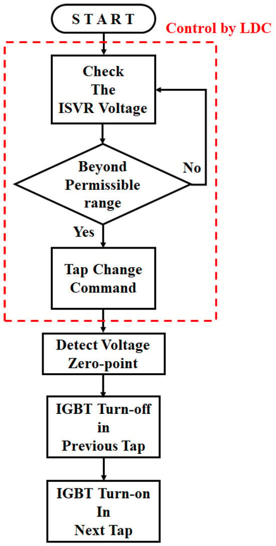
Figure 14.
Tap-changing procedures with voltage zero-point control method.
4. Simulation and Results
To verify normal tap switching of the ISVR, a simulation is conducted for a single distribution line. Figure 15 Shows a single 22.9 kV distribution line model, which is branched off from the 154 kV/22.9 kV, 45 MVA substation.

Figure 15.
A typical distribution system model to be analyzed.
The main transformer of the substation was 154 kV/22.9 kV, 3-phase 45 MVA, and the neutral point of the transformer was grounded through the reactor. The underground cable CNCV-325 was used from the 22.9 kV substation outlet to the 500 m point, and from the 500 m point onwards, the overhead line ALOC 160-95 consists of 20 km. The distribution line was divided into 20 sections and a 0.5 MVA load was connected every 1 km. The total load of the distribution line is an inductive load of 10 MVA at a heavy load and 2.5 MVA at a light load, and both have a load power factor of 0.9. The components and parameters of the model distribution systems are as shown in Table 3.

Table 3.
Components and parameters for model distribution systems.
To compensate for the 5% voltage drop in the distribution line, an ISVR with a voltage adjustment range of ±5% is modeled in Figure 16, which uses a B-type series transformer. The has a turn ratio of 1:1 (660:660 V) and the has a turn ratio of 1:20 (660:13,200 V). The parallel transformer is a 4-winding transformer, and the total secondary rating voltage is 660 V; the turn ratio of the 2nd, 3rd, and 4th windings is 1:3:2 (110:330:220 V). The % impedance of all transformers is 2%, and their capacity is 200 kVA, respectively.
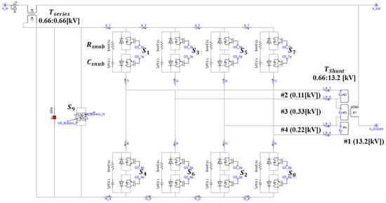
Figure 16.
Modeling through PSCAD/EMTDC.
As described above, there are a total of 13 voltage levels that can be controlled through the combination of a parallel transformer and a switching element. Eight bidirectional IGBTs perform switching operations during tap changing, and one bidirectional thyristor switch is used in bypass mode in the event of a fault or a malfunction in the internal circuit of the tap switching transformer. Table 4 shows the operation switches and compensation voltage according to tap position number.

Table 4.
Operation switches and compensation voltage according to tap position number.
Based on a load of 10 MVA, the current flowing in a single line is about 252A and considering the maximum compensation voltage of 660 V, the capacity of and is 200 kVA. The rated voltage of the IGBT and diode considers the maximum compensation voltage. The rated current considers the size of the load current and fault current on the IGBT. The ratings of the IGBT and diode that satisfy the two conditions are 1700 V and 800 A. Considering the same conditions for the thyristor, the rated voltage and current are 1800 V, 570 A. The parameters used in the ISVR are set by referring to Infineon’s data sheets. The snubber resistor () is 10 Ω, and the snubber capacitor () is 1.0 uF. The components of a single-phase ISVR are listed in Table 5.

Table 5.
Specification of single-phase ISVR for simulations.
Based on the above description, the ISVR circuit modeled through PSCAD/EMTDC is shown in Figure 16.
4.1. Simulation Scenario
To prove the stable control of the proposed method, the simulation is divided into the following three cases: case I applied the current-limiting resistor method, case II applied the zero-current switching method, and case III applied the zero-voltage switching method to the ISVR. The simulation considers peak load.
Lastly, we will also verify the protection performance of the bypass switch in case of a single-line ground fault (SLGF).
4.2. Simulation Results
The voltage variation during tap changing in case I is shown in Figure 17. The horizontal axis represents the tap-switching time as seconds, and the vertical axis represents the voltage p.u. based on 22.9 kV. The blue line is the voltage just after the SVR, and the red line represents the voltage at the end of the line. It is known that large voltage drops occur due to the current-limiting resistance when changing tap. This voltage drop occurs while passing through the current-limiting resistor after the tap change signal is applied, that is, during the tap-changing delay.
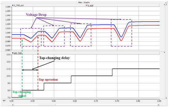
Figure 17.
Voltage variation during tap changing in case I.
Figure 18 shows the voltage () at the series transformer during tap switching. The vertical axis of the upper graph represents the instantaneous voltage kV on the secondary side of the series transformer of the SVR, the vertical axis of the lower graph represents the tap position number, and the horizontal axis represents the tap-switching time as seconds. Here, too, it can be seen that voltage drops occur due to the current-limiting resistor when changing taps.
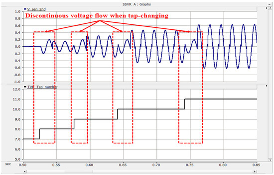
Figure 18.
Voltage () at the series transformer during tap switching in case I.
Figure 19 shows the voltage variation for peak load in case II when current zero-point detection is not performed accurately. The vertical axis of the upper graph represents the voltage p.u. on the distribution line based on 22.9 kV, the vertical axis of the lower graph represents the tap position number, and the horizontal axis represents the tap-switching time as seconds. In particular, when switching from tap 8 to 9, it can be seen that a short circuit occurs, resulting in a large voltage drop.
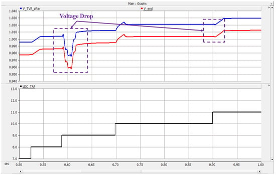
Figure 19.
Voltage variation during tap changing in case II.
Figure 20 shows the voltage variations in case III. In the ISVR using the zero-voltage switching method, unlike cases I and II, it is confirmed that no voltage drop occurs during tap changing and stable operation is achieved.
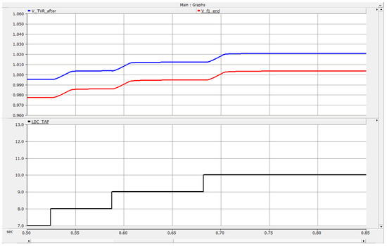
Figure 20.
Voltage variation during tap changing in case III.
Figure 21 shows the voltage () at the series transformer during tap switching. The vertical axis of the upper graph represents the instantaneous voltage kV on the secondary side of the series transformer of the SVR, the vertical axis of the lower graph represents the tap position number, and the horizontal axis represents the tap-switching time as seconds. Also, we can check for a stable voltage waveform.
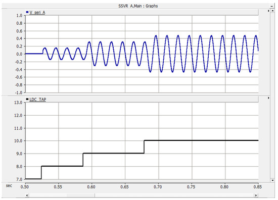
Figure 21.
Voltage () at the series transformer during tap switching in case III.
Lastly, let us check the ISVR protection according to the bypass circuit operation in the event of an SLGF on the distribution line. Figure 22a shows the current flowing in the ISVR circuit when the bypass circuit is not operating. Figure 22b shows the current flowing in the ISVR circuit during bypass circuit operation. The vertical axis of each graph represents the instantaneous current value kA, and the horizontal axis represents the time as seconds considering the SLGF occurrence. The top two graphs represent the current flowing in two switches out of eight switches, and the bottom graph represents the current in bypass switch 9. An SLGF occurs at 1.2 s and lasts for 0.2 s.
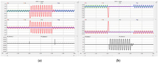
Figure 22.
Currents flowing in ISVR during SLGF: (a) when the bypass switch does not operate; (b) when the bypass switch operates.
When the bypass is not operating, the fault current flows through the IGBT switches, but when the bypass is operating, the fault current flows through the bypass, so they can be protected from the fault current.
5. Experiment and Results
In this section, we will introduce the contents of the ISVR prototype produced and tested. The prototype specifications of the ISVR are shown in Table 6. The overall configuration of the system for verification testing is shown in Figure 23. Based on the single-line phase nominal voltage of 13.2 kV in the target distribution system, 13 taps are operated in stages. The compensation voltage per tap is the same as the ISVR topology in Section 3.

Table 6.
Specifications of prototype single-phase ISVR for experiments.
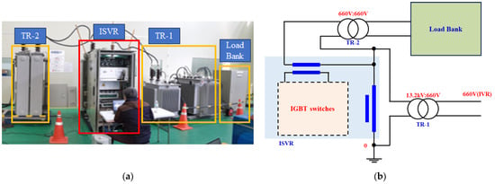
Figure 23.
The configuration for verification testing: (a) a picture of the entire experimental facility; (b) experiment wiring diagram.
Figure 24 shows the compensation voltage when the tap position number of the ISVR is from 1 to 13. In the graph, the yellow line represents the secondary voltage V of in Figure 7, the green line represents the secondary current A of in Figure 7, and the purple line represents the secondary voltage V of in Figure 7.
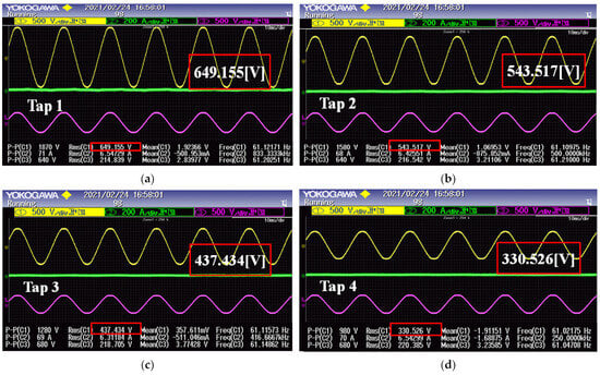
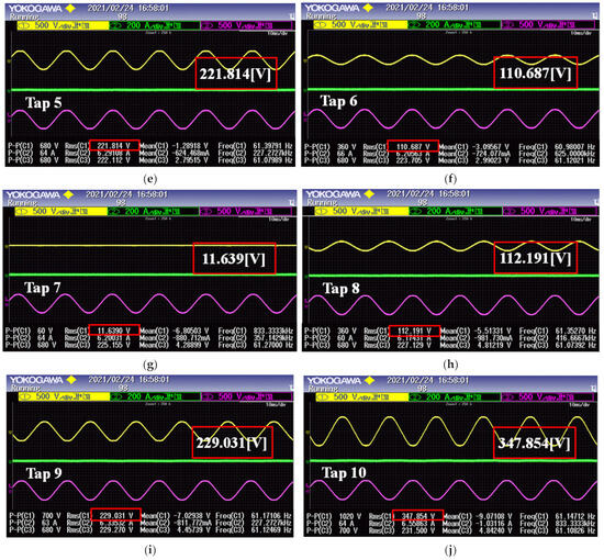
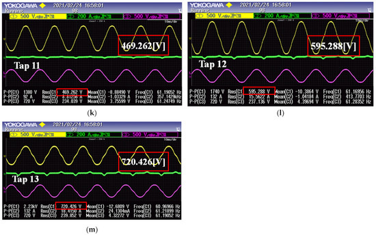
Figure 24.
Compensation voltage of series transformer at () different tap position numbers: (a) tap 1; (b) tap 2; (c) tap 3; (d) tap 4; (e) tap 5; (f) tap 6; (g) tap 7; (h) tap 8; (i) tap 9; (j) tap 10; (k) tap 11; (l) tap 12; (m) tap13.
Figure 24a–f show the case where the RMS voltage compensated for in the series transformer is −660 ~ −110 V, but the actual compensated voltage values are −649.155 V, −543.517 V, −437.434 V, −330.526 V, −221.814 V, and −110.687 V. Figure 24h–m show the case where the effective value voltage compensated for in the series transformer is 110 ~ 660 V, but the actual compensated voltage values are 112.191 V, 229.031 V, 347.854 V, 469.262 V, 595.288 V, and 720.426 V. It is confirmed that generally good voltage compensation was achieved.
6. Conclusions
As energy transition takes place around the world, the penetration of large-scale variable DG like as PV generation into distribution systems is increasing, resulting in frequent voltage fluctuations in distribution lines. As a result, the voltage of the distribution line may be beyond the allowable range, making it difficult to supply appropriate voltage to consumers. The voltage of existing long-distance distribution lines has been adjusted through SVRs. Existing SVRs are mostly mechanical and have disadvantages such as a slow tap-changing rate, arcing, and a shortened life span in response to frequent operation requirements due to output changes in DG. Also, TVRs and hybrid SVRs developed so far have the disadvantage of short circuits and open circuits due to complex control methods and current zero-point control.
To solve those disadvantages, this paper proposes an SVR using IGBT devices, which have an efficient topology and a zero-voltage switching method. To validate the proposed method, software simulations and empirical experiments were conducted.
In the former case, the target distribution system and ISVR were modeled and simulated by PSCAD/EMTDC. As a result, much more stable tap switching was achieved compared to the conventional current limiting resistor method and zero-current switching method. In addition, it was confirmed that the ISVR circuit can be safely protected from fault current through bypass circuit operation in the event of an SLGF.
In the latter case, an ISVR with a capacity of 400 kVA, voltages of 13.2 kV, 1700 V, and 800 A, IGBT elements, a 660:660 V series transformer, and a 13.2:0.66 kV parallel transformer was built and connected to a 13.2 kV power system to perform tap-switching experiments. The results of the empirical experiments showed that stable voltage compensation at a total of 13 tap positions was well achieved.
It is hoped that this ISVR will be applied to distribution lines with large-scale DG and the line voltage will be effectively regulated within the permissible range. However, if a control error or defect occurs in the power semiconductor and the rating is exceeded, the ISVR may be damaged. Therefore, some protection devices for those instances need to be developed, and this is a future research subject.
Author Contributions
Methodology, J.-E.K.; software & writing—original draft, M.-G.L.; validation, J.-B.K. and K.-J.P.; data curation, J.-W.S. and Y.-J.K.; funding acquisition & supervision & writing—review & editing, J.-E.K. All authors have read and agreed to the published version of the manuscript.
Funding
This research was supported by the Basic Science Research Program through the National Research Foundation of Korea (NRF), funded by the Ministry of Education (No. 2020R1A6A1A12047945).
Data Availability Statement
Data are contained within the article.
Acknowledgments
We would like to thank Eul-Jae Lee and Hong-Won Lee at E-Kyoung Industrial Systems company for building experimental equipment, performing the experiment, and providing us with successful experimental results of our SVR based on IGBT.
Conflicts of Interest
The authors declare no conflict of interest.
References
- Dohnal, D. On-load tap changers for power transformers. A Tech. Dig. 2009, in press.
- Harlow, J.H. Electric Power Transformer Engineering, 2nd ed.; Taylor & Francis Group: Abingdon, UK, 2006. [Google Scholar]
- Ram, G.; Prasanth, V.; Bauer, P.; Bärthlein, E.-M. Comparative Analysis of On-Load Tap Changing (OLTC) Transformer Topologies. In Proceedings of the International Power Electronics and Motion Control Conference and Exposition, Antalya, Turkey, 21–24 September 2014; pp. 918–923. [Google Scholar]
- Roy, N.K.; Pota, H.R. Current Status and Issues of Concern for the Integration of Distributed Generation into Electricity Networks. IEEE Syst. J. 2015, 9, 933–944. [Google Scholar] [CrossRef]
- Tonkoski, R.; Turcotte, D.; EL-Fouly, T.H.M. Impact of High PV Penetration on Voltage Profiles in Residential Neighborhoods. IEEE Trans. Sustain. Energy 2012, 3, 518–527. [Google Scholar]
- Rogers, D.J.; Green, T.C. A Hybrid Diverter Design for Distribution Level On-Load Tap Changers. In Proceedings of the IEEE Energy Conversion Congress and Exposition, Atlanta, GA, USA, 12–16 September 2010; pp. 1493–1500. [Google Scholar]
- Faiz, J.; Siahkolah, B. Differences between Conventional and Electronic Tap-changers and Modifications of Controller. IEEE Trans. Power Deliv. 2006, 21, 1342–1349. [Google Scholar] [CrossRef]
- Erbrink, J.J.; Gulski, E.; Smit, J.J.; Seitz, P.P.; Quak, B.; Leich, R.; Malewski, R. Diagnosis of On-load Tap Changer Contact Degradation by Dynamic Resistance Measurements. IEEE Trans. Power Deliv. 2010, 25, 2121–2131. [Google Scholar] [CrossRef]
- Mouli, G.R.C.; Bauer, P.; Wijekoon, T.; Panosyan, A.; Bärthlein, E.-M. Design of a Power-Electronic-Assisted OLTC for Grid Voltage Regulation. IEEE Trans. Power Deliv. 2015, 30, 1086–1095. [Google Scholar] [CrossRef]
- Martinez, E.; Fernandez, I.; Canales, J.M. Thyristor based Solid State Tap Changer for Distribution Transformers. In Proceedings of the IEEE 11th International Workshop of Electronics, Control, Measurement, Signals and Their Application to Mechatronics, Toulouse, France, 24–26 June 2013; pp. 1–5. [Google Scholar]
- Ma, H.; Gu, S.; Wang, H.; Xu, H.; Wang, C.; Zhou, H. On-load Automatic Voltage Regulation System Designed via Thyristor for Distribution Transformer. In Proceedings of the International Conference on Electrical Machines and Systems (ICEMS), Sydney, NSW, Australia, 11–14 August 2017; pp. 1–5. [Google Scholar]
- Jiang, H.; Shuttleworth, R.; Al Zahawi, B.A.T.; Tian, X.; Power, A. Fast Response GTO Assisted Novel Tap Changer. IEEE Trans. Power Deliv. 2001, 16, 111–115. [Google Scholar] [CrossRef]
- Sosnina, E.; Kralin, A.; Kryukov, E.; Bedretdinov, R. Research of Thyristor Voltage Regulator Characteristics in Transverse Output Voltage Regulation Mode. In Proceedings of the IEEE PES Innovative Smart Grid Technologies Europe (ISGT-Europe), The Hague, The Netherlands, 26–28 October 2020; pp. 960–964. [Google Scholar]
- Sosnina, E.; Petritskiy, S.; Iurtaev, S.; Kryukov, E. Research of Thyristor Voltage Regulator Effect on the Harmonics in the Distribution Electric Network. In Proceedings of the IEEE PES Innovative Smart Grid Technologies Europe (ISGT-Europe), Bucharest, Romania, 29 September–2 October 2019; pp. 1–5. [Google Scholar]
- Echavarria, R.; Cotorogea, M.; Claudio, A.; Sanchez, V. Design and Implementation of a Fast On-Load Tap Changing Regulator, Conference Record of the 2000 IEEE Industry Applications Conference. In Proceedings of the Thirty-Fifth IAS Annual Meeting and World Conference on Industrial Applications of Electrical Energy (Cat. No.00CH37129), Rome, Italy, 8–12 October 2000; Volume 4, pp. 2078–2085. [Google Scholar]
- Sasaki, Y.; Yoshida, T.; Seki, N. High Speed TVR for Power Distribution Lines and its Test Results. JEEJ Trans. P E 2003, 123, 1105–1110. [Google Scholar] [CrossRef]
- Betancourt, E.; Mendez, O.; Rivas, D. Distribution Transformer with Electronic Tap Changer Featuring Robust Low Current Zero Switching. In Proceedings of the 2014 IEEE PES T&D Conference and Exposition, Chicago, IL, USA, 14–17 April 2014; pp. 1–4. [Google Scholar]
- Lopez, J.V.; Rodriguez, J.C.C.; Fernandez, S.M.; Garcia, S.M.; Garcia, M.A.P. Analysis of Fast On-Load Multitap-changing Clamped-hard-switching AC Stabilizers. IEEE Trans. Power Deliv. 2006, 21, 852–861. [Google Scholar]
- Lokhande, N.M.; Kulkarni, S.; Ghone, V.; Kikale, V.; Patharkar, R. Design and Implementation of TRIAC based On-Load Tap Changer with Primary Tappings for Constant Output Voltage. In Proceedings of the International Conference for Convergence in Technology (I2CT), Mumbai, India, 8–9 April 2017; pp. 106–109. [Google Scholar]
- Hernández, C.; Gallegos, C.; Vazquez, N.; Rodríguez, E.; Orosco, R. A Different AC Voltage Regulator based on Tapped Transformer. In Proceedings of the IEEE International Power Electronics Congress, San Luis Potosi, Mexico, 21–24 June 2010; pp. 180–184. [Google Scholar]
- Echavarria, R.; Claudio, A.; Cotorogea, M. Analysis, Design, and Implementation of a Fast On-Load Tap Changing Regulator. IEEE Trans. Power Electron. 2007, 22, 527–534. [Google Scholar] [CrossRef]
- de Oliveira Quevedo, J.; Cazakevicius, F.E.; Beltrame, R.C.; Marchesan, T.B.; Michels, L. Analysis and Design of an Electronic On-Load Tap Changer Distribution Transformer for Automatic Voltage Regulation. IEEE Trans. Ind. Electron. 2017, 64, 883–894. [Google Scholar] [CrossRef]
- Gao, J.; Ge, J.; Zhang, J.; Hu, X.; Li, T.; Wu, J.; Su, Y. Hardware circuit design of on-load voltage regulation switch based on high power IGBT. In Proceedings of the IEEE Advanced Information Technology, Electronic and Automation Control Conference (IAEAC), Chongqing, China, 25–26 March 2017; pp. 22–25. [Google Scholar]
- Benbouzid, M.; Delpha, C.; Khatir, Z.; Lefebvre, S.; Diallo, D. Faults Detection and Diagnosis in a Static Converter; WILEY: Hoboken, NJ, USA, 2011. [Google Scholar]
- Tabbache, B.; Kheloui, A.; Benbouzid, M.E.H.; Mamoune, A.; Diallo, D. Research on Fault Analysis and Fault-tolerant Control of EV/HEV Powertrain. In Proceedings of the First International Conference on Green Energy ICGE 2014, Sfax, Tunisia, 25–27 March 2014; pp. 284–289. [Google Scholar]
- Faiz, J.; Siahkolah, B. Electronic Tap Changer for Distribution Transformers; Springer: Berlin/Heidelberg, Germany, 2011. [Google Scholar]
- Ismail, A.A.A.; Alsuwaidi, H.; Elnady, A. Automatic Voltage Stabilization Using IGBT Based on Load Tap Changer with Fault Consideration. IEEE Access 2021, 9, 72769–72780. [Google Scholar] [CrossRef]
- Wang, Q.; Li, L.; Wang, Y. An Efficient Zero-Voltage Switching Resonant Pole Inverter with High Reliability. IEEE Trans. Circuits Syst. II Express Briefs 2023, 70, 156–160. [Google Scholar] [CrossRef]
- Saadatizadeh, Z.; Heris, P.C.; Mantooth, H.A. Zero Voltage Switching High Step Up/Down Bidirectional DC-DC Converter Utilizing Three-Winding Coupled Inductors. In Proceedings of the IEEE Southern Power Electronics Conference (SPEC), Nadi, Fiji, 5–8 December 2022; pp. 1–6. [Google Scholar]
- IEC. 60076–21; Power Transformers—Part 21: Standard Requirements, Terminology, and Test Code for Step-Voltage Regulators. IEC: Geneva, Switzerland, 2018.
- Kim, J.B.; Lee, M.G.; Lee, J.H.; Ryu, J.C.; Choi, T.S.; Park, M.S.; Kim, J.E. Control Method of Step Voltage Regulator on Distribution Lines with Distributed Generation. Energies 2022, 15, 9579. [Google Scholar] [CrossRef]
- Feng, C.; Liu, L.-G.; Mao, G.-M.; Liu, S.-X. Research on control strategy of thyristor voltage regulator in distributed generation system. In Proceedings of the International Conference on Critical Infrastructure (CRIS), Beijing, China, 20–22 September 2010; pp. 1–4. [Google Scholar]
Disclaimer/Publisher’s Note: The statements, opinions and data contained in all publications are solely those of the individual author(s) and contributor(s) and not of MDPI and/or the editor(s). MDPI and/or the editor(s) disclaim responsibility for any injury to people or property resulting from any ideas, methods, instructions or products referred to in the content. |
© 2024 by the authors. Licensee MDPI, Basel, Switzerland. This article is an open access article distributed under the terms and conditions of the Creative Commons Attribution (CC BY) license (https://creativecommons.org/licenses/by/4.0/).