Abstract
Research on engine operation using hydrogen may enable appropriate optimization of thrust, and therefore performance, related to its potential use in aircraft. It is particularly important as the share of hydrogen in combustion affects the reduction of combustion products such as carbon dioxide, carbon monoxide, nitrogen oxide, hydrocarbons, and solid matter. This is in line with the new requirements regarding the increased supply of sustainable aviation fuels (SAFs) and the related changes in emissions, i.e., reducing the harmful impact of exhaust gases on the environment. This paper presents the results of measurements carried out in the GTM400 MOD turbojet engine. Based on the research performed, the impact of hydrogen and aviation kerosene combustion on selected engine parameters is presented. The paper shows changes in the rotational speed and volume flow of JET A-1 fuel as a function of engine operation time. Changes in temperature measured at the edge of the flame tube were also examined. The tests confirmed that the combustion chamber worked correctly in the selected area in the range of the tested fuel mixtures. After incorporating hydrogen into the combustion process, the consumption of traditional JET A-1 fuel was significantly reduced.
1. Introduction
Exhaust gases from turbine jet engines can be divided into three groups. The first is natural products of fuel combustion, i.e., CO2, H2O, and NOx. The second group includes products of inefficient combustion: CO, HC, and soot. The third group is emissions related to fuel quality, i.e., sulphides and residue particles such as metals. Harmful combustion products result from various causes. Carbon monoxide is produced in the combustion chamber when there is a rich fuel–air mixture. Too little oxygen leads to incomplete oxidation of carbon to carbon dioxide [1,2,3]. In the case of hydrocarbons, the main causes include, among others, poor fuel atomization leading to incomplete combustion, as well as the combustion speed being too low [4]. Nitrogen oxide may be formed in several ways, i.e., as a result of the oxidation of atmospheric nitrogen in the combustion chamber behind the flame, in the initial phase of oxidation of the combustion process of rich fuel–air mixtures with a low flame temperature, and also as a result of the oxidation of nitrogen contained in the fuel [5,6,7,8].
Changes in emission intensity have been introduced as a result of new European Union regulations. The RefuelEU initiative has emerged and is a key part of the EU’s Fit for 55 package [9]. These regulations are already partially in force. One of the requirements from 2025 is the use of a 2% admixture of sustainable aviation fuels (SAFs). The scope of these fuels includes certified biofuels, renewable fuels of non-biological origin, including renewable hydrogen, and aviation fuels with recycled coal [10]. By 2050, this admixture is expected to constitute 70%.
Hydrogen was used as an alternative fuel for testing in the co-combustion process. Hydrogen fuel is called emission-free, which means that the only combustion products are water and steam, with trace amounts of nitrogen oxides. Compared to commonly used hydrocarbon fuels, it is characterized by, among others, greater reactivity and diffusivity, high flame speeds, and wide flammability limits. Compared to JET A-1 fuel (approx. 43 MJ/kg), it is characterized by a higher specific energy value (120 MJ/kg) [11]. There are various works that analyze hydrogen combustion in engines and its possible commercial application [12,13,14,15,16,17]. The literature provides information on the combustion of not only hydrogen but also other alternative fuels [18,19,20]. It is estimated that hydrogen is currently one of the most important alternative fuels [21]. It is generally expected that hydrogen could replace kerosene in jet engines of large aircrafts. For this reason, many analyses in the literature concern the use of liquid hydrogen [22]. Currently, the use of such a drive is primarily associated with the problem of fuel storage, because it requires a low temperature of 20 K [23,24]. Therefore, the practical application of this promising technology requires more time. In the case of smaller machines, due to their lower efficiency in this case, hydrogen fuel cells will be used [21,25]. Hydrogen in gaseous form can be used to power them. Examples include the modified ATR72 and De Havilland Canada Dash-8 and ZA600 aircraft. Distances that are more than twice as long as when using electric batteries can be achieved. This has been confirmed by an analysis in the literature [26]. A less advanced and simpler solution is a traditional turbojet engine powered by kerosene and hydrogen gas. One advantage of this solution, among others, is that the supplied hydrogen is not a liquid, like kerosene, which prevents the formation of a local stoichiometric fuel/air region of high temperature near the evaporating fuel drop [27].
Miniature turbojet engines are a convenient tool for research on the use of various fuels and admixtures. This is due to the fact that their operating costs are much lower than those of normal-scale engines. In this type of turbojet engine, a combustion chamber in an annular configuration is most often used. There is quasi-reverse flow there. Some of the air behind the compressor moves towards the return channel and is then mixed with fuel in the evaporator. In this way, an air–fuel mixture is created and directed inside the combustion chamber, where it is ignited. The flame tube in this engine model is made of Inconel 600. The safe operating limit of this material is considered to be the range of 870–1230 °C [28]. Thermodynamic and numerical analyses related to flow and combustion in the combustion chamber are also available in the literature [29,30,31]. However, it should be emphasized that the processes occurring in miniature turbojet engines take place in small spaces and in a short time. Therefore, experimental research in this area is particularly desirable.
Currently, research using turbojet engine is at an early stage. The aim of this study was to check the impact of the co-combustion of JET A-1 fuel and hydrogen on the fuel consumption of the GTM400 MOD miniature turbojet engine. An additional goal was to check the temperature distribution in a selected place of the combustion chamber depending on the engine speed. The measuring point was located near the outer flame tube. This made it possible to verify whether it was overheating or not due to a high gas temperature. There is no information in the literature on temperature measurements in the combustion chamber during the co-combustion of kerosene and hydrogen for this engine model. More advanced methods of combustion control, as well as control of the temperature in the combustion chamber, will be implemented after the analysis of engine operation in the current conditions. The research should also make it possible to assess whether the inclusion of hydrogen in co-combustion requires many design changes for its proper operation over a useful, wide range of rotational speeds.
2. Research Method
Experimental tests were carried out on the GTM400 MOD turbojet engine from JETPOL. The motor position is shown in Figure 1.
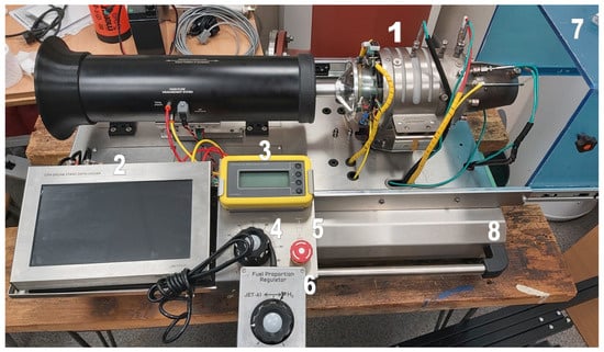
Figure 1.
Engine test stand: 1—GTM400 MOD engine, 2—control and measurement equipment with data acquisition and touch screen, 3—external digital module for engine control, 4—power regulator, 5—starter switch, 6—hydrogen flow regulator, 7—protective cover, 8—platform with elements for mounting the engine.
The engine is characterized by the following technical parameters:
- thrust: 15–300 N;
- rotational speed: 30,000–81,000 rpm;
- mass air flow: 0.59 kg/s;
- fuel consumption: 0.82 kg/min;
- engine dimensions: 15 cm (diameter), 39 cm (length);
- total mass: 2.9 kg.
In addition, a hydrogen installation from Linde Gaz Polska was used for testing. It consists of:
- control cabinet;
- semi-automatic high-pressure reduction panel type READLINE A200;
- low-pressure reducing panel type W40B;
- hydrogen cylinders;
- tubes, connections, and hoses.
Technical hydrogen was used for the tests, the purity of which is 99.955%. It was taken from the cylinder through hoses and directed to pressure reducers. The task of the READLINE A200 reduction panel was to reduce the pressure to 20 × 105 Pa. Then, the gas reached the second low-pressure reducer (W40B), where the pressure was reduced to 8 × 10⁵ Pa. The producer of both pressure reducers is Linde Gaz Polska. The connections of the reducers and the output to the flow controller were 6 mm external diameter tubes made of stainless steel. The basic technical data of the READLINE A200 reduction panel are as follows:
- input pressure: 200–300 × 105 Pa;
- output pressure: 14 or 28 × 105 Pa +/− 3 × 10⁵ Pa;
- semi-automatic cylinder switching;
- has a working gas flushing system (preventing oxygen and moisture from entering the installation);
- has a safety valve that prevents excessive pressure from the cylinder from entering the installation.
The basic technical data of the W40B reducer are as follows:
- input pressure: 40 × 105 Pa;
- output pressure: 0.1–1 × 10⁵ Pa or 0.5–6 × 10⁵ Pa or 0.5–10 × 105 Pa.
The pressure reducers with hydrogen cylinders connected to them are shown in Figure 2. The yellow–green wire visible in the figure was used to ground the installation.
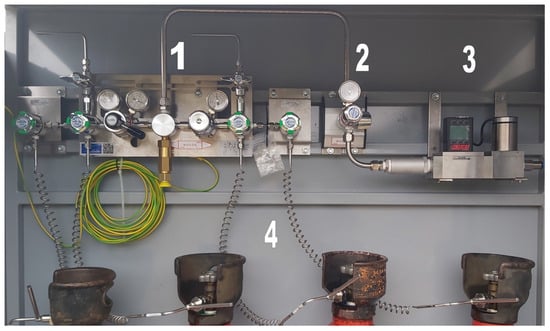
Figure 2.
Hydrogen installation: 1—READLINE A200 reduction panel, 2—W40B pressure reducer, 3—MCR-2000SLPM flow controller, 4—hydrogen cylinders.
Additionally, the stand was equipped with the MCR-2000SLPM flow controller (regulator and flowmeter) from Alicat Scientific. This device is designed to work with among other gases, hydrogen. The basic technical data of the flow controller are as follows:
- -
- flow measurement range: 2000 standard L/min;
- -
- pressure measurement accuracy: +/−0.5% of full scale;
- -
- temperature measurement accuracy: +/−0.75 °C.
A flow controller was also placed in the control cabinet. Hydrogen at reduced pressure was sent to the flow controller, where its flow was regulated. It was then directed to the engine through a flexible hose. There, together with JET A-1 fuel, hydrogen was injected into the evaporator. In the GTM400 MOD engine, the injectors are located at the inlet to the evaporators. JET A-1 fuel and gaseous hydrogen were fed independently through tubes with an internal diameter of 0.6 mm. The JET A-1 fuel was injected at a pressure of 4 × 10⁵–5 × 10⁵ Pa, forced by a gear pump. The location of the experiment and the hydrogen connection point are shown in Figure 2.
As mentioned earlier, the pressure after the second reducer was 8 × 10⁵ Pa. However, the pressure continued to change at the point where the flow measurement took place because the control valve control valve was located there. By moving the hydrogen flow regulator (Figure 1) located next to the engine, a signal was sent to the controller in the hydrogen connection station (Figure 3) whether the control valve should open or close more. The information that controlled and measured when the engine was powered with hydrogen was the flow.
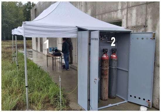
Figure 3.
Place of research: 1—engine test stand, 2—hydrogen installation.
An S-type thermocouple was used to measure the temperature inside the combustion chamber, the maximum operating temperature of which is 1600 °C. The sensor is 9 cm long. In addition to the distance of the internal areas of the engine, the selection of the sensor length should take into account the distance of its mounting (Figure 4). It consists of a sleeve, a nut, and a screw.
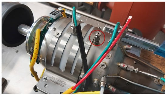
Figure 4.
Thermocouple mounting location—marked with a red circle.
The nut was screwed onto a threaded sleeve permanently located in the engine housing. A screw with a hollow hole for the sensor acted as its lock. The sleeve, nut, and screw together formed the sensor mount, and their total length was 3.2 cm. The mounting was located 16.8 cm from the inlet. During the tests, the sensor was inserted into the chamber at a distance of 0.28 cm from the inside of the flame tube.
The combustion process is controlled based on two parameters. The first one is the rotational speed. If the speed is reduced below 24,000 rpm or increases above 83,000 rpm, an emergency shutdown occurs. After calibrating the engine, the relationship between the voltage on the JET A-1 fuel pump and the rotational speed is also defined in its software. The program allows voltage ranges that deviate from the characteristics. In the case of operation in hybrid mode, these ranges are larger, as in the case of operation using only aviation kerosene. The increase in the amount of supplied JET A-1 fuel takes place more slowly, so that the rotational speed increases more slowly. The second parameter controlled during engine operation is the temperature in the turbine section. It is measured between the stator and the rotor. The engine operates properly within the maximum range of 350–860 °C. The engine was started using JET A-1 fuel. After setting a specific rotational speed, the hydrogen supply valve was opened using a dedicated knob. This information was transmitted to the flow controller, which served as an additional regulator. Thanks to this, a specific hydrogen flow value was set. The dedicated hydrogen supply knob also transmitted information about the presence of additional fuel to the engine software, which translated into the previously mentioned voltage regulation on the JET A-1 fuel pump.
During the tests, the temperature varied in the range of 13.7–16.2 °C, the ambient pressure was 100,160 Pa. The turbojet engine was started twice. During the first start-up, the rotation speed was set to 40,000 rpm. During operation, after adjusting the speed, the cylinder valve was opened and hydrogen was supplied to the combustion chamber. Due to the fact that the impact of hydrogen on the engine operation was not fully known, increasingly higher flow values were assumed. However, the difference between them had to be clear to observe possible sudden changes in parameters. While adding hydrogen, the measured parameters were monitored, e.g., temperature in the combustion chamber, turbine, and possible larger fluctuations in rotational speed. The following flow rate values were set on the flow controller: 25 L/min (191 standard L/min), 50 L/min (381 standard L/min), and 93.4 L/min (712 standard L/min). The conversion from litres per minute to standard litres per minute is performed in the flow controller. During the second start-up, the rotation speed was set to 50,000 rpm. In this case, the following hydrogen volume flows were used during operation: 50 L/min and 93.4 L/min. As a result of the hydrogen flow into the engine, the rotational speed increased. After the recorded increase in rotational speed, it was reduced to the initial value, i.e., 40,000 rpm (during first start-up) and 50,000 rpm (during second launch). The speed change occurred as a result of reducing the JET A-1 fuel supply.
3. Results
The tests took into account three parameters, i.e., rotational speed, flow rate, and temperature near the inner edge of the flame tube. In the first period after starting the engine, it operated using only aviation kerosene. Three points are marked in the drawings below: point 1—the beginning of hydrogen combustion; point 2—the peak of rotational speed (also on the graphs of other parameters); and point 3—stabilization of fluctuations of the parameter in question. These are approximate points.
During the first start-up, hydrogen injection began after approximately 475 s, 744 s, and 1029 s. The hydrogen flow rate was increased each time. A larger amount of fuel mixture resulted in an increase in rotational speed. The most dynamic increase was recorded for the largest flow, i.e., 93.4 L/min. The dynamics of the speed increase is more important in the analysis, not the speed value. The second value is influenced by the human reaction time (better or worse depending on the moment) and is less reliable. The changes in rotational speed for the first engine start are presented in Figure 5.
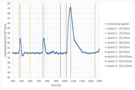
Figure 5.
Change in rotational speed as a function of time—speed stabilization for 40,000 rpm.
The appearance of hydrogen in the combustion chamber during engine operation is also illustrated by the change in the flow rate of the JET A-1 fuel (Figure 6). Its values decrease approximately successively by 45 mL/min, 98 mL/min, and 167 mL/min compared to the values where combustion took place without hydrogen.
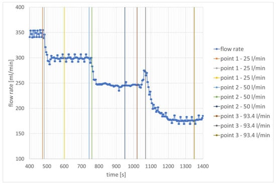
Figure 6.
Change in JET A-1 fuel flow rate as a function of time—speed stabilization for 40,000 rpm.
The share of hydrogen influenced temperature changes at the edge of the glow tube in different ways. The results are presented in Figure 7. The smallest hydrogen stream causes a slight decrease in the temperature at the measurement point from 677 °C to 663 °C. Increasing the hydrogen stream to 50 L/min increases the temperature to 738 °C. However, after the rotational speed stabilizes, the temperature continues to rise and increases further to 748 °C. The subsequent increase in the hydrogen stream causes the temperature to increase to 758 °C.
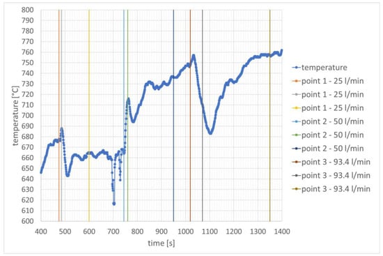
Figure 7.
Temperature distribution over time in the combustion chamber—speed stabilization for 40,000 rpm.
During the second start-up, hydrogen injection began after approximately 1240 s and 1400 s. Similarly to the previous stage of the study, there is a noticeable increase in rotational speed when the hydrogen injection into the combustion chamber begins. However, it can be seen that when comparing all mixtures, the values of the changes in rotational speeds are smaller (Figure 8).
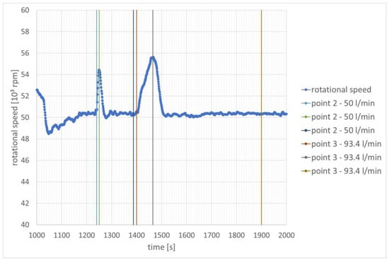
Figure 8.
Change in rotational speed as a function of time—speed stabilization for 50,000 rpm.
Providing hydrogen leads to a significant reduction in the engine’s demand for kerosene. The JET A-1 fuel flow values are reduced by approximately 100 mL/min and 185 mL/min compared to the values when combustion takes place without hydrogen at the same rotational speed.
After increasing the rotational speed, hydrogen combustion caused an increase in temperature at the inner edge of the flame tube. In the case of hydrogen dosing with a stream of 50 L/min, the temperature increased from 627 °C to 732 °C. Further, in the time interval from 1439 s to 1512 s, a significant temperature oscillation was recorded, in which two minimum temperature values can be distinguished. The second minimum value, recorded at 1512 s, is related to the reduction in rotational speed while increasing the hydrogen flow to 93.4 L/min. The first one is related to temporarily turning the hydrogen flow regulator in the opposite direction. Similar temperature oscillations can be seen in Figure 6, where they also occurred in the moment before a larger hydrogen flow was set. The temperature change corresponds to the change in JET A-1 fuel flow in Figure 9 during this specific time interval, which confirms the explanation presented. In the case of hydrogen dosing with a stream of 50 L/min, the temperature increased from 627 °C to 698 °C. Later it increased further to 732 °C and then decreased to 710 °C. In the case of hydrogen dosing with a stream of 93.4 L/min, an increase in temperature to 796 °C was observed. It can be considered that it was later stabilized and no significant changes were observed. The temperature changes are shown in Figure 10.
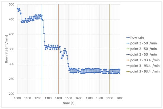
Figure 9.
Change in JET A-1 fuel flow rate as a function of time —speed stabilization for 50,000 rpm.
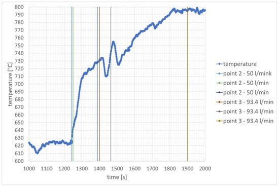
Figure 10.
Temperature distribution over time in the combustion chamber—speed stabilization for 50,000 rpm.
4. Discussion
The analysis showed how the JET A-1 fuel consumption changes when hydrogen is burned in selected amounts at the same time. For the same conditions, a control measurement of a selected place at the edge of the flame tube in the combustion chamber was also carried out.
During the first engine start-up, the test showed that hydrogen injection in the amount of 25 L/min, 50 L/min, and 93.4 L/min resulted in reductions in the JET A-1 fuel flow to 87.0%, 71.6%, and 51.6% in relation to the combustion of clean aviation fuel. It follows that the adopted hydrogen streams cover 13%, 28.4%, and 48.4% of the energy demand for the JET A-1 fuel to operate at a speed of 40,000 rpm. During the second engine start, hydrogen injection at rates of 50 L/min and 93.4 L/min resulted in reductions in the JET A-1 fuel flow to 78.3% and 59.8% in relation to the combustion of clean aviation fuel. It follows that the adopted hydrogen streams cover 21.7% and 40.2% of the energy demand for the JET A-1 fuel to operate at a speed of 50,000 rpm.
The use of the same hydrogen flows does not ensure an adequate increase in energy of the alternative fuel in relation to the increase in rotational speed. However, they were adopted for two reasons. First of all, the analysis wanted to check exactly what differences would appear in the amount of replaced fuel using the same flow for different rotational speeds. This applies to flows of 50 L/min and 93.4 L/min. Secondly, it turned out that it was not possible to transfer larger amounts of hydrogen in the existing design configuration. This was for two related reasons. The first was the hydrogen pressure being too low. The second one was related to the diameter of the pipes in the fuel system being too small. It was not possible to create a significantly higher pressure due to the limitation of the flowmeter used, which could operate in conditions up to 10 × 105 Pa (absolute pressure).
The measurement analysis also confirmed that mixing both fuels in the combustion process leads to an increase in temperatures in the combustion chamber. For the highest hydrogen share, this increase was approximately 80 °C for 40,000 rpm and almost 180 °C for 50,000 rpm. Considering that this is the area around the edge of the flame tube, the temperature change can be considered significant. However, the temperature does not exceed the permissible values for Inconel 600. The analysis of the temperature measurements in the combustion chamber indicates that operating the engine using only hydrogen may significantly shorten the engine’s life due to the consumption of materials operating at too high temperatures. For this reason, higher rotational speeds may not be achievable. At the lowest rotational speeds, including engine start-up, temperature changes will not be so significant, as shown by the analysis. In this case, however, a higher hydrogen flow value may be needed and, based on the previous comments, engine modernization will be necessary. This may concern primarily the replacement or use of another collector. The same applies to the pipes that connect the collector with the return channel.
The analysis confirmed that the use of hydrogen in a turbojet engine within the range of analyzed rotational speeds is possible and safe. Hydrogen can replace traditional kerosene for use in turbojet engines. It is assumed that hydrogen will become cheaper over time due to its widespread availability in nature. Therefore, this chemical compound has the potential to become a more economical and cleaner fuel in the aviation industry. Therefore, further research on the engine is being considered.
The research could be extended by taking measurements in other places in the combustion chamber, as well as increasing the probing depth. Additionally, it is worth examining the impact of the co-combustion of hydrogen and JET A-1 fuel on the temperatures at the outlet from the combustion chamber. This would allow for a better assessment of the possible higher thermomechanical load on the guide vanes and turbine rotor. The analysis carried out by incorporating hydrogen into the combustion process in a selected turbojet engine showed that while maintaining the same rotational speeds, the JET A-1 fuel consumption was reduced by approximately 50%. It can therefore be concluded that the emission of harmful combustion products was significantly reduced. For this purpose, exhaust emission testing is also planned for a later stage.
In the longer term, a change in the design related to the installation of fuel injectors using liquid hydrogen is considered in order to analyze the engine operation. This allows for better control of the combustion process in the combustion chamber. However, this will require numerous tests to develop the full characteristics of the engine and its possible optimization in terms of the combustion process.
Funding
This research was funded by the Polish Ministry of Science and Higher Education, number 0712/SIGR/5232.
Data Availability Statement
Data is contained within the article.
Conflicts of Interest
The author declares no conflict of interest.
References
- Kotlarz, W.; Piaseczny, L.; Rypulak, J.; Zadrąg, R. Testy toksyczności spalin turbinowego silnika lotniczego dla warunków startu i lądowania. Combust. Engines 2006, 45, 61–73. [Google Scholar] [CrossRef]
- Masiol, M.; Harrison, R.M. Aircraft Engine Exhaust Emissions and other airport-Related Contributions to Ambient Air Pollution: A Review. Atmos. Environ. 2014, 95, 409–455. [Google Scholar] [CrossRef]
- Łapucha, R. Komory Spalania Silników Turbinowo-Odrzutowych; Biblioteka Naukowa Instytutu Lotnictwa: Warszawa, Poland, 2004. [Google Scholar]
- Lefebre, A. Gas Turbine Combustion, 2nd ed.; Taylor & Francis: Philadelphia, PA, USA, 1998. [Google Scholar]
- Jeż, M. Airport Environmental Impact—Methodology of Atmosphere Protection; Institute of Aviation Scientific Library: Warsaw, Poland, 2007. [Google Scholar]
- Gieras, M. Komory Spalania Silników Turbinowych. Organizacja Procesu Spalania; Oficyna Wydawnicza Politechniki Warszawskiej: Warszawa, Poland, 2010. [Google Scholar]
- Dzierżanowski, P.; Kordziński, W.; Otyś, J.; Łyżwiński, M.; Szczeciński, S.; Wiatrek, R. Napędy Lotnicze. Turbinowe Silniki Odrzutowe; Wydawnictwo Komunikacji i Łączności: Warszawa, Poland, 1983. [Google Scholar]
- Jarosiński, J. Techniki Czystego Spalania; Wydawnictwo Naukowo-Techniczne: Warszawa, Poland, 1996. [Google Scholar]
- Proposal for a Regulation of the European Parliament and of the Council on Ensuring a Level Playing Field for Sustainable Air Transport—‘ReFuelEU Aviation’—General Approach, Council of the European Union, 2021/0205(COD), 9805/22. 2022. Available online: https://eur-lex.europa.eu/legal-content/en/ALL/?uri=CELEX%3A52021PC0561 (accessed on 3 January 2024).
- Regulation of the European Parliament and of the Council on Ensuring a Level Playing Field for Sustainable Air Transport (RefuelUE Aviation), The European Parliament, the Council, PE-CONS 29/23. 2023. Available online: https://data.consilium.europa.eu/doc/document/PE-29-2023-INIT/en/pdf (accessed on 4 January 2024).
- Onorati, A.; Payri, R.; Vaglieco, B.M.; Agarwal, A.K.; Bae, C.; Bruneaux, G.; Canakci, M.; Gavaises, M.; Günthner, M.; Hasse, C.; et al. The role of hydrogen for future internal combustion engines. Int. J. Engine Res. 2022, 23, 529–540. [Google Scholar] [CrossRef]
- Dahl, G.; Suttrop, F. Engine control and low-NOx combustion for hydrogen fuelled aircraft gas turbines. Int. J. Hydrogen Energy 1998, 23, 695–704. [Google Scholar] [CrossRef]
- Stepien, Z. A comprehensive overview of hydrogen-fueled internal combustion engines: Achievements and future challenges. Energies 2021, 14, 6504. [Google Scholar] [CrossRef]
- Wang, B.; Zhao, D.; Li, W.; Wang, Z.; Huang, Y.; You, Y.; Becker, S. Current technologies and challenges of applying fuel cell hybrid propulsion systems in unmanned aerial vehicles. Prog. Aerosp. Sci. 2020, 116, 100620. [Google Scholar] [CrossRef]
- Prokopowicz, W.; Frąckowiak, A. A proposal of a hydrogen injection system in to a miniature turbojet engine. J. KONBiN 2023, 53, 79–94. [Google Scholar] [CrossRef]
- Tang, X.; Kabat, D.M.; Natkin, R.J.; Stockhausen, W.F.; Heffel, J. Ford P2000 Hydrogen Engine Dynamometer Development; SAE 2002-01-0242; SAE International: Warrendale, PA, USA, 2002. [Google Scholar]
- Welch, A.; Mumford, D.; Munshi, S. Challenges in Developing Hydrogen Direct Injection Technology for Internal Combustion Engines; SAE 2008-01-2379, SAE International Technical Papers; Westport Innovations Inc.: Vancouver, BC, Canada, 2008. [Google Scholar]
- Seyam, S.; Dincer, I.; Agelin-Chaab, M. Novel hybrid aircraft propulsion systems using hydrogen, methane, methanol, ethanol and dimethyl ether as alternative fuels. Energy Converion Manag. 2021, 28, 114172. [Google Scholar] [CrossRef]
- Balli, O.; Caliskan, N.; Caliskan, H. Aviation, energy, exergy, sustainability, exergoenvironmental and thermoeconomic analyses of a turbojet engine fueled with jet fuel and biofuel used on a pilot trainer aircraft. Energy 2023, 263, 126022. [Google Scholar] [CrossRef]
- Badami, M.; Nuccio, P.; Pastrone, D.; Signoretto, A. Performance of a small-scale turbojet engine fed with traditional and alternative fuels. Energy Convers. Manag. 2014, 82, 219–228. [Google Scholar] [CrossRef]
- Cecere, D.; Giacomazzi, E.; Ingenito, A. A review on hydrogen industrial aerospace applications. Int. J. Hydrogen Energy 2014, 39, 10731–10747. [Google Scholar] [CrossRef]
- Tiwari, S.; Pekris, M.J.; Doherty, J.J. A review of liquid hydrogen aircraft and propulsion technologies. Int. J. Hydrogen Energy 2024, 57, 1174–1196. [Google Scholar] [CrossRef]
- Otto, M.; Chagoya, K.L.; Blair, R.G.; Hick, S.M.; Kapat, J.S. Optimal hydrogen carrier: Holistic evaluation of hydrogen storage and transportation concepts for power generation, aviation, and transportation. J. Energy Storage 2022, 55, 105714. [Google Scholar] [CrossRef]
- Khandelwal, B.; Karakurt, A.; Sekaran, P.R.; Sethi, V.; Singh, R. Hydrogen powered aircraft: The future of air transport. Prog. Aerosp. Sci. 2013, 60, 45–59. [Google Scholar] [CrossRef]
- Funke, H.W.; Beckmann, N.; Abanteriba, S. An overview on dry low NOx micromix combustor development for hydrogen-rich gas turbine applications. Int. J. Hydrogen Energy 2019, 44, 6978–6990. [Google Scholar] [CrossRef]
- Adler, E.J.; Martins, J.R.R.A. Hydrogen-powered aircraft: Fundamental concepts, key technologies, and environmental impacts. Prog. Aerosp. Sci. 2023, 141, 100922. [Google Scholar] [CrossRef]
- Yusaf, T.; Mahamude, A.S.F.; Kadirgama, K.; Ramasamy, D.; Farhana, K.; Dhahad, H.A.; Talib, A.R.A. Sustainable hydrogen energy in aviation—A narrative review. Int. J. Hydrogen Energy 2024, 52, 1026–1045. [Google Scholar] [CrossRef]
- Specification Sheet: Alloy 600; UNS N06600; Sandmeyer Steel Company: Philadelphia, PA, USA, 2022.
- Görtz, A.; Silberhorn, D. Thermodynamic potential of turbofan engines with direct combustion of hydrogen. In Proceedings of the 33rd Congress of the International Council of the Aeronautical Sciences, Stockholm, Sweden, 4–9 September 2022. [Google Scholar]
- Semlitsch, B.; Hynes, T.; Langella, I.; Swaminathan, N.; Dowling, A.P. Entropy and Vorticity Wave Generation in Realistic Gas Turbine Combustors. J. Propuls. Power 2019, 35, 839–849. [Google Scholar] [CrossRef]
- Ekrataleshian, A.; Pourfayaz, F.; Ahmadi, M.H. Thermodynamic and thermoeconomic analyses and energetic and exergetic optimization of a turbojet engine. J. Therm. Anal. Calorim. 2020, 145, 909–923. [Google Scholar] [CrossRef]
Disclaimer/Publisher’s Note: The statements, opinions and data contained in all publications are solely those of the individual author(s) and contributor(s) and not of MDPI and/or the editor(s). MDPI and/or the editor(s) disclaim responsibility for any injury to people or property resulting from any ideas, methods, instructions or products referred to in the content. |
© 2024 by the author. Licensee MDPI, Basel, Switzerland. This article is an open access article distributed under the terms and conditions of the Creative Commons Attribution (CC BY) license (https://creativecommons.org/licenses/by/4.0/).