Abstract
Modular multilevel converters (MMCs) with integrated battery energy storage systems (BESSs) are becoming crucial for modern power grids. This paper investigates the modeling and control of a grid-connected MMC-BESS, with a specific emphasis on state-of-charge (SoC) balancing. Compared to conventional hard arm SoC balancing control (HASBC), this paper proposes an alternative soft arm SoC balancing control (SASBC). The simulation results and analysis indicate the following: 1. SASBC provides superior performance in achieving SoC balance both between and within the arms, as compared to HASBC. 2. The MMC-BESS power fluctuates between phases, arms, and individual submodules to balance the SoC of batteries. After the accomplishment of SoC equalization, the power is equally distributed, and the circulating current is well eliminated. 3. MMC-BESS can operate in both the charging and discharging modes, and the total harmonic distortion (THD) of the output current is reduced from 6.80% to 1.13% after SoC balancing is achieved. 4. A robustness test shows the control system’s effective performance in handling component variations.
1. Introduction
According to the International Electrotechnical Commission (IEC), the share of renewable energy in the global power sector will reach 8108 TWh in the year 2025, representing a 100% increase compared to 2009. The increasing penetration of renewable energy sources has led to a growing need for grid modernization and upgrading the infrastructure to accommodate higher levels of renewable generation. One crucial aspect of grid modernization is addressing increasing voltage level requirements [1]. Consequently, the demand for a high-performance, scalable multilevel converter becomes inevitable to efficiently convert power from renewable energy sources to the grid while supporting the transmission of renewable energy over longer distances and reducing transmission losses [2,3]. Battery energy storage systems (BESSs) are progressively utilized to balance the variable generation of renewable energy sources and provide grid stability and flexibility while integrating larger amounts of renewable generation. BESSs need to be interfaced with the grid by utilizing advanced power electronics and control systems to enhance flexibility, grid stability, and reliable power flow [4,5]. A modular multilevel converter (MMC) is a recent advanced high-power electronic device that is utilized to convert electrical energy between DC and AC [6]. The MMC is flexible to scale up or down to meet the power requirements of the system, and it is advantageous for constant balancing generation and load, high system reliability and efficiency, and stable control performance compared to traditional power converters [7]. Therefore, it is prospective to embed a BESS into an MMC and integrate with the grid to support a more sustainable, reliable, and resilient modern grid.
Some of the recent literature has made contributions to the applications of the MMC-BESS system. It is reported that the MMC system with distributed battery sources has higher efficiency, reliability, and versatility compared to the MMC with a centralized BESS [4]. For the distributed MMC-BESS, it is crucial to realize the SoC equalization among phases, between upper and lower arms, and among submodules within one arm. The individual SoC balancing [8] can be realized by the carrier rotation method [9,10], sorting algorithm [11,12,13], and modulation reference adjustment [14,15]. Leg/phase and arm SoC balancing can be achieved by a zero-sequence injection [15,16], a negative-sequence current injection [17], and circulating current control [18,19,20,21,22,23]. Zero-sequence voltage injections and negative-sequence current injections can realize SoC balancing among phases by incorporating deviation power into the input/output power reference. The balancing process needs to be performed in active operation and is not feasible in standby mode. On the other hand, by utilizing circulating current control, the MMC-BESS can achieve phase SoC balancing and arm SoC balancing even in standby mode [8]. Specifically, leg SoC balancing is realized by regulating the DC component of the circulating current, and arm SoC balancing is performed by regulating the fundamental component of the circulating current from the three phases of the MMC, which has been discussed in detail in [18,19,20,21,22,23]. The method used to balance the SoC between the upper and lower arms by employing fundamental circulating current from the three phases is referred to as hard arm SoC balancing control (HASBC) in this paper. By regulating the fundamental circulating current, the power can be injected into the arms, realizing SoC balancing between the upper and lower arms. In [24], the authors introduced the power control of individual submodules by using a power ratio factor, phase power control by choosing a common-mode voltage, and arm power control by HASBC. Based on the power control of individual submodules, phases, and arms, three-level SoC balancing is realized with a proportional controller. The control methods under DC and AC fault modes were investigated in [25], where HASBC is used to balance the SoC in the DC-side fault mode by injecting fundamental circulating current, and the DC component is regulated to balance the SoC in the AC-side fault mode. The authors in [26] analyzed the gain calculation of the grid-connected power–current double-closed control and proposed a self-adaption control based on an online SoC capacity estimation. The SoC convergence rate and overmodulation of submodules are discussed in [27], which highlights that the methods mentioned above are not always optimal and that SoC may not converge in some cases. For instance, in [28], the SoC will not converge and the system will become unstable when the average power of the arm cannot be equal to zero. Moreover, it is pertinent to acknowledge that, in scenarios involving three-phase variables, the circulating currents are confined solely to the MMC converter, and their total value is inherently constrained to be equal to zero. Assuming the arm SoCs in all three phases are taken into consideration in the control, as in the HASBC, the sum of the generated circulating current references can potentially violate the zero rule and cause conflicts in the arm SoC balancing. For example, from the figure of all SoCs of battery stacks in [21], it can be noticed that during the discharging mode, while all the SoC profiles decline, they can be separated into two groups, which potentially indicates that the SoCs of the upper arm and lower arm are split into two values, which are not well balanced.
Therefore, this paper aims to address the limitations of the HASBC by proposing an alternative soft arm SoC balancing control (SASBC). In the SASBC, rather than the three-phase arm SoCs adopted in the HASBC, two out of the three arm SoCs are taken in the loop, and the minus sum of the produced circulating current references in the selected two phases is considered the third circulating current reference. Compared to the HASBC, the SASBC consistently adheres to the principle of maintaining zero total current flow in the circulating currents. This unwavering compliance not only elevates the efficiency of the balancing operation but also enables a more flexible and effective distribution of the SoCs between and within the arms. Therefore, the SASBC is an advanced and preferable alternative for the SoC management of an MMC-BESS.
The rest of this paper is organized as follows: Section 2 introduces the configuration of the MMC-BESS system and mathematically analyzes the converter behaviors and balancing principles. Section 3 presents control scenarios with respect to the grid-connected power control, the circulating current control, and the SoC balancing control. The results and analysis are described in Section 4 to verify the operating characteristics of the proposed MMC-BESS. Section 5 concludes this paper.
2. MMC-BESS Modeling and Analysis
2.1. MMC-BESS Configuration
The schematic diagram of the MMC-BESS considered in this paper is illustrated in Figure 1. The MMC-BESS has three phases, and each phase contains two symmetrical arms in the upper and lower branches. In each arm, there are N identical submodules connected in series together with an arm inductor. The arm inductor is able to suppress the MMC-BESS circulating current, limit its fault current, and reduce current ripples. The submodule is integrated with battery banks, one capacitor, and a bidirectional half-bridge converter composed of two power switches with freewheeling diodes. With N submodules per arm, the MMC-BESS can generate three-phase line-to-line AC voltages with (2N + 1) levels. The voltage stress across each semiconductor is restricted to the battery module voltage. The battery pack can either be charged or discharged, depending on the switch’s actions and the current direction.
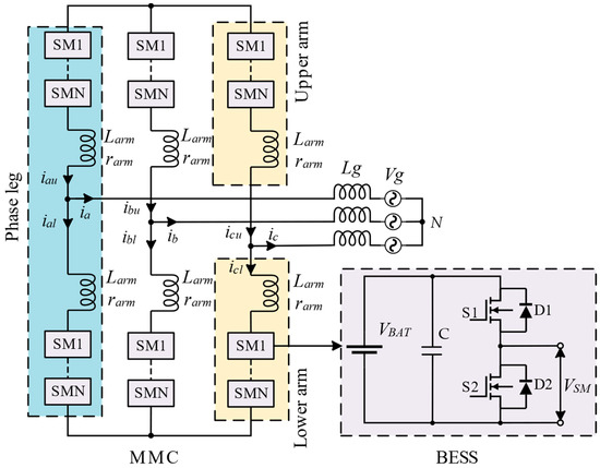
Figure 1.
Schematic diagram of MMC-BESS with half-bridge submodules.
2.2. MMC-BESS Modeling and Analysis
2.2.1. MMC-BESS System Modeling
Assuming that there are N submodules in each arm and each submodule battery pack shares the same voltage, then the maximum voltage on each arm is . The upper and lower arms in the same phase are regulated complementarily, with a focus on maintaining the voltage constant between the positive and negative busbars. According to the Kirchhoff voltage law, the voltages in the upper and lower arms are as follows:
where represents the fundamental output voltage, and all the quantities referred to in the three phases are expressed with the subscript x; and are the voltage drops across the upper and lower arm inductors. Assuming the resistance of the arm inductors is small and can be neglected, the voltage drop across the arm inductors can be calculated by the derivative of the current flowing through them, which is given by the following:
where is the circulating current flowing within the MMC-BESS system, and is the output current. The current flowing through the arm inductor is referred to as the upper arm current and lower arm current , which are expressed as and in Equations (4) and (5). The relations between the MMC-BESS output current, circulating current, and upper/lower arm current are expressed as follows:
The circulating current contains DC and harmonic components, which can be expanded with the Fourier series as follows:
where is the DC component of the circulating current, represents the amplitude of the h-th harmonic component, and is the corresponding phase angle.
By substituting Equations (4)–(7), the MMC-BESS outer and inner dynamic equations can be yielded as follows:
As stated in Equations (10) and (11), the output current can be managed by tuning the difference between the upper arm and lower arm voltages, and by regulating the sum voltage of the upper arm and the lower arm, the circulating current is under control. Consequently, the voltage difference and sum of the upper arm and lower arm contribute to the output current and circulating current driving voltages, which are presented as follows:
2.2.2. MMC-BESS SoC Balancing Analysis
The battery packs can be discharged and charged by the submodule switching events and current direction. The corresponding battery current can be described by means of battery SoC and capacity as follows:
where and denote the current flowing into or out of the battery banks in the k-th submodule in the upper arm and lower arm, respectively, is the battery capacity, and and are the k-th submodule corresponding SoCs. Based on each single and , the average SoC of the arm, phase, and whole system can be calculated as follows:
where and represent the average upper/lower arm SoCs, denotes the average phase SoC, and is the individual average SoC of the whole MMC-BESS system.
Under the assumption of ideal switches and battery packs, the power of the battery packs in each submodule can be obtained by [19] as follows:
where and are the k-th submodule battery power in the upper arm and lower arm, respectively. Then, the power of the upper arm and lower arm can be calculated by the sum of all independent submodules in that arm, which can be expressed in Equations (22) and (23) after being substituted by Equations (16) and (17):
where and represent the power of the upper arm and lower arm, respectively. According to the arm power and the relationship in Equation (18), the power of each phase and its differential value can be obtained as follows:
As stated above, the arm power is calculated from the perspective of battery voltage and current. Additionally, arm power can be yielded from the perspective of arm voltage and arm current, as shown below:
Similarly, the arm power summation and its difference are yielded as follows:
The right sides of Equations (24), (25), (28) and (29) are equal to each other. Assuming and and ignoring the alternating terms, the new equations to describe the SoC can be yielded with the substitution of Equation (9) into (28) and (29) (see and Appendix A.1 and Appendix A.2):
From Equation (30), it is indicated that the DC component of the circulating current can contribute to achieving SoC equalization between different phases in the MMC-BESS. Additionally, Equation (31) shows that the SoC between the upper arm and lower arm can be balanced by adjusting the fundamental component of the circulating current.
3. MMC-BESS Control Strategy
The control system of the MMC-BESS comprises grid-connected power control, circulating current control, and SoC balancing control. The grid-connected power control is the control top level, which regulates the power exchange between the grid and BESS with a desired output voltage following the grid. The circulating current control is responsible for eliminating the circulating current flowing within the converter, which can be disadvantageous in the steady state of the MMC-BESS. The SoC balancing control consists of three parts: the phase SoC balancing control, the arm SoC balancing control, and the individual SoC balancing control. With the benefit of the SoC balancing control, SoC equalization can be achieved among the phases, arms, and submodules.
3.1. Grid-Connected Power Control
The grid-connected power control structure is shown in Figure 2 by using the prominent dual-loop control method in the rotating reference frame. Here, is the grid voltage, and the PLL detects and synchronizes with the grid frequency. The outer-loop controller, as the power controller, tracks the commanded active power and reactive power, subsequently producing reference values for the active current and reactive current . The inner-loop controller, tasked with tracking the current references, generates the direct and quadrature voltage components, which are inversely transformed to generate the output voltage reference [7]. In terms of power flow, since the proposed MMC-BESS has no external DC link, the power only flows between the battery modules and the AC grid side during both the charging and discharging modes under balanced conditions. Before the realization of SoC balancing, the phase power is redistributed from the phase with a higher SoC to the phase with a lower SoC by using the DC circulating current component, as presented in Equation (30). Similarly, arm power is transferred from the arm with a higher SoC to the one with a lower SoC by leveraging fundamental circulating current, as stated in Equation (31). Notably, the power flow adjustments made to facilitate SoC balancing remain internal to the converter, even in scenarios of SoC imbalance. Consequently, the power exchange between the battery side of the converter and the AC grid side consistently aligns with the command values and . Additional details regarding the implementation of grid-connected power control can be found in reference [26].
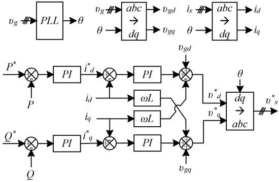
Figure 2.
Grid-connected power control.
3.2. Circulating Current Control
The circulating current only flows within the converter system and has little impact on the output current. However, since the circulating current causes distortion in the arm current and additional power losses, it is required to be eliminated. The arm inductor can suppress the circulating current to a certain degree [29], but to fully eliminate it, an active regulator is needed. Since the circulating current is dominated by second-order harmonics, the eliminator is mainly designed to suppress this component. As reported in the literature, the most prominent circulating current control methods are based on a PI controller and a proportional resonant (PR) controller. In this paper, the quasi-PR (QPR) controller is utilized due to its wider bandwidth and more practical implementation compared to the PR controller [30,31,32,33], and the control block diagram is shown in Figure 3.
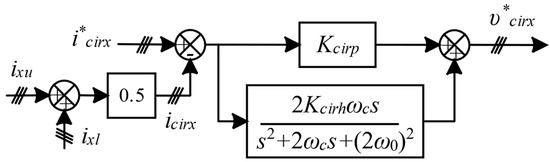
Figure 3.
Circulating current control.
The transfer function of the QPR controller is given as follows:
where and are the proportional and integral coefficients of the QPR controller, and denote the cut-off and resonant angular frequency. The introduced cut-off frequency can prevent a loss of sensitivity in the QPR controller when the frequency shifts, and the shift should be limited to a range of [33]. Therefore, the margin of the cut-off frequency can be set as follows:
where is the fundamental frequency, assuming Hz, and then the cut-off frequency margin is . The transfer function of the plant is as follows:
The open-loop transfer function of the circulating current control can be expressed as follows:
The selection of the coefficients of the QPR controller will be discussed in Section 3.3. SoC Balancing Control. In this paper, the coefficients are set as , , and . Given a 10 mH inductor used in the arm, the Bode plot of the circulating current open-loop transfer function can be obtained, as shown in Figure 4. From the Bode plot, it indicates that the circulating current control is stable with a good gain margin and a phase margin of 34.3° at a frequency of 936.5 rad/s. Additionally, it is shown from the Bode plot that the resonant frequency is 628.3 rad/s, aligning with the targeted second-order harmonics. As the frequency increases, a significant decrease in magnitude is observed. This trend is counteracted at the resonant frequency of 628.3 rad/s, where the magnitude increases. This particular characteristic underscores the enhanced capability of the circulating current control to eliminate the component at the specified second-order frequency.
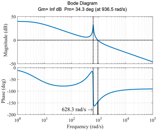
Figure 4.
Bode plot of the circulating current control.
3.3. SoC Balancing Control
The SoC balancing control contains the phase SoC balancing control, the arm SoC balancing control, and the individual submodule SoC balancing control. In this paper, we propose an alternative soft arm SoC balancing control (SASBC) compared to conventional hard arm SoC balancing control (HASBC). In the HASBC, the circulating current references generated by the arm SoC balancing controller from the three phases are applied to balance the SoC between the upper and lower arms in the three phases. Instead, the components of two phases are utilized in the SASBC, and the minus sum of the produced circulating current references in the selected two phases is taken as the third circulating current reference.
Firstly, in terms of phase SoC balancing, it drives the three-phase to be the same value as . If is less than , more power tends to be required in the corresponding phase, and vice versa, less power is required. The power distribution among phases is achieved by regulating the DC component of the circulating current. The control scheme is visualized in Figure 5a, where LPF is the low-pass filter to extract the DC component from the circulating current, and the command DC component is generated by the outer-loop controller as follows:
where and denote the proportional and integral coefficients of the outer-loop PI controller. The modulation voltage reference of the phase SoC balancing control is created by the inner controller, which is given by the following:
where and represent the proportional and integral gains of the inner-loop PI controller. In order to reduce the computational burden, there is no need to detect the current direction.
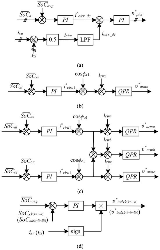
Figure 5.
SoC balancing control: (a) phase SoC balancing control; (b) HASBC; (c) SASBC; (d) individual SoC balancing control.
With respect to arm SoC equalization, HASBC is widely applied, where all SoC variables of the three phases are taken into account in the arm SoC balancing control, as shown in Figure 5b. However, the circulating current only flows within the MMC converter, and the sum of the circulating currents is equal to zero.
Assuming the arm SoCs in all three phases are used in the control, as in the HASBC, the sum of the generated circulating current references could potentially violate Equation (38) and cause conflicts in the arm SoC balancing. Therefore, SASBC is proposed where the arm SoCs of two phases are adopted rather than those of three phases, as shown in Figure 5c, and the minus sum of the produced circulating current references in the selected two phases is taken as the third circulating current reference. Similar to the power flow in the phase SoC control scheme, the power is transferred from the arm with the greater SoC to the arm with less SoC. The command for the fundamental component of the circulating current is given as follows:
where and are the proportional and integral gains of the inner-loop arm SoC controller, respectively. Similarly to the circulating current controller, the QPR controller is adopted to regulate the fundamental harmonics. The final modulation reference of the arm SoC balancing control is expressed as follows:
where is the transfer function of the fundamental circulating current controller. For the fundamental current, the plant transfer function is as follows:
In Section 3.2, the margin of the cut-off frequency is discussed. is chosen to have a desired bandwidth around the resonant frequency. In the arm SoC balancing control, the resonant frequency is equal to the grid frequency. should be calculated within the boundary to have a good transient response and stability. It is assumed that the modulation time delay is half of the sampling period ; therefore, the transfer function of the modulation PWM can be written as follows [33]:
The delay can be approximated by poles and zeros to simplify the calculation with reasonable accuracy by using the first-order Pade approximation, as shown in Equation (46).
Substituting Equation (46) into Equation (45), can be approximated as follows:
Then, the boundary of can be calculated according to the open-loop transfer function by using Routh’s stability criterion. Assuming , the characteristic equation can be yielded as follows:
where is the upper boundary of the proportional coefficient under different values. By using the MATLAB symbolic solver, the boundary of can be obtained as follows:
The value of is chosen to help eliminate phase and magnitude steady-state errors. Before estimating the corresponding phase margin can be assumed according to [34] as follows:
where denotes the crossover frequency, and the time constant can be obtained approximately by the crossover frequency as follows [35]:
Then, the resonant coefficient can be estimated by considering the time constant in relation to the proportional coefficient as follows:
Given the coefficients , the Bode plot of the fundamental circulating current control is presented in Figure 6 with a good gain margin and a phase margin of 69.3° at a frequency of 2146 rad/s. The resonant frequency can be observed at 314.2 rad/s. Similar to the second-order circulating current eliminator, the magnitude decreases while the frequency increases, but it is pulled up at the fundamental resonant frequency. This particular characteristic shows the enhanced tracking capability of the fundamental circulating current to balance the SoC between the upper and lower arms.
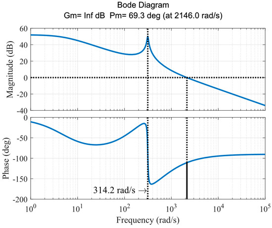
Figure 6.
Bode plot of the fundamental circulating current control.
The individual SoC equalization is achieved with a simple PI controller, as shown in Figure 5d, and the sign of the arm current is incorporated to adjust the control signal.
where and are the proportional and integral coefficients of the individual SoC controller.
Figure 7 provides an overview of the control strategy for the MMC-BESS. Firstly, the grid voltage and output current are measured and sent to the grid-connected power control, and the command active and reactive power are assigned to generate the output voltage reference (, , and ). Secondly, the leg SoC balancing control and arm SoC balancing control adjust the references (, , and ) and (, , and ) caused by the unbalanced phase and arm SoCs. Then, the circulating current control is used to eliminate the circuiting current by using the command (, , and ). The individual SoC balancing control deals with each submodule SoC and generates the individual SoC control signal (, , and ()). All reference signals generated by the grid-connected power control, leg/arm/individual SoC balancing control, and circulating current control are combined to generate the final modulation references for each submodule. These references are then sent to the modulator to produce the gating signals for each switch of the submodule to realize the objectives of the control strategy.
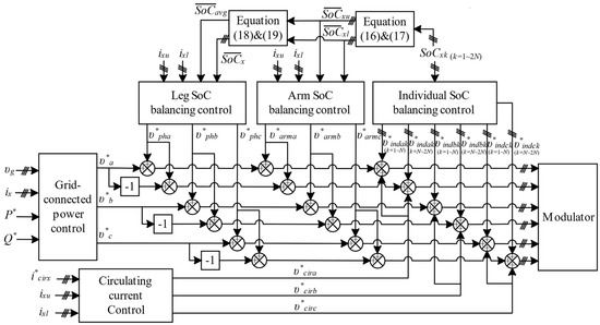
Figure 7.
Overview of control strategy for MMC-BESS.
4. Results and Analysis
In order to explore the operating characteristics of the proposed MMC-BESS, a simulation model was prepared in MATLAB/Simulink®R2020b. The specification of the simulated MMC-BESS is shown in Table 1.

Table 1.
Specification of the simulated MMC-BESS.
The MMC-BESS system has 6 submodules in each arm branch, i.e., 36 submodules in total. The nominal voltage of each battery bank is assumed to equal 1000 V. The MMC-BESS is a grid-connected converter used for stationary applications, where the connected grid voltage is RMS 2000 V in phase-to-phase and rotates at 50 Hz. Since the rechargeable batteries need to be charged and discharged from the grid, there are two operation modes in the model, which are the charging mode and the discharging mode. Additionally, the system’s nominal power level is ±1 MW. The simulated inductance of the arm inductor is 10 mH, which is obtained as follows [36]:
where is the switching cycle duration, is the maximum ripple current, and is the maximum arm voltage.
The important input signals of the MMC-BESS system are the active power and reactive power references, which are carried as [−1 MW, 1 MW] and [0 W, 0 W] at time [0 s, 10 s], respectively, as shown in Figure 8. P and Q present the actual active power and reactive power, respectively. Under the regulation of the power controller, the actual active power and reactive power are forced to track the reference values.
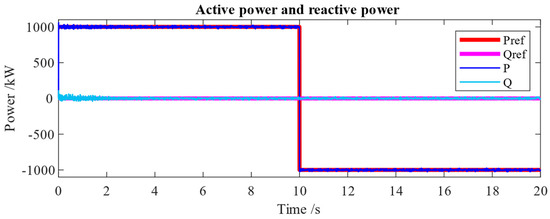
Figure 8.
Grid active power (P) and reactive power (Q) at 1 MW charging and 1 MW discharging.
To better explore the power flow and conversion of the MMC-BESS, the power distribution among phases, arms, and individual submodules is demonstrated graphically in Figure 9. The phase power and arm power (Figure 9a) are not equally distributed among phases and arms initially, which happens because at the start of the operation, the phase and arm SoC profiles are not balanced. As aforementioned in the balancing control, more power would be captured by the phase/arm with less SoC, and vice versa. Similarly, Figure 9b provides the individual submodule power distribution of the MMC-BESS. After realizing the SoC balancing, the power is equally distributed among the phases, arms, and individual submodules.
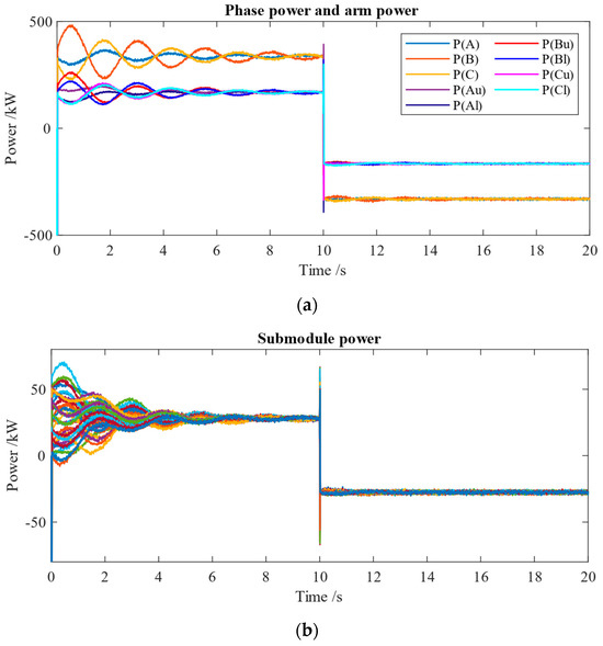
Figure 9.
Power distribution with 1 MW (charging and discharging) operation: (a) phase power and arm power; (b) submodule power.
Under the command of the grid-connected power control, the output voltage of the MMC-BESS matches the rotating grid voltage, and the output current is forced to follow the voltage to contribute to the target power in the charging mode and inversely align with it in the discharging mode, as shown in Figure 10.
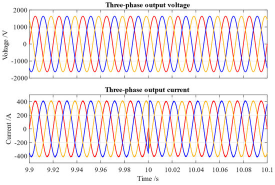
Figure 10.
Output voltage and current from charging mode to discharging mode.
The realization of balancing control is based on controlling the circulating current. The circulating current is calculated by measuring the upper arm and low arm currents. After the balancing achievement, the circulating current is disadvantageous in terms of the arm current quality and power losses, which are required to be eliminated. Figure 11 presents the simulated output current, arm current, and circulating current. From Figure 11a, it is shown that the circulating current reaches 40 A, and the waveforms of the output current and the current in the upper arm and lower arm yield some distortions at the start of the operation. As shown in Figure 11b, the circulating current is eliminated, and the output current and arm current are less distorted in a balanced situation.
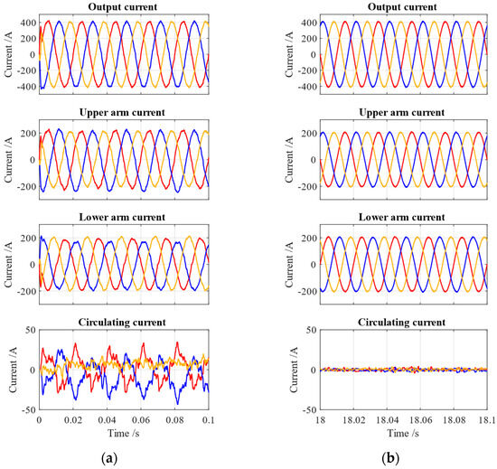
Figure 11.
Arm current and circulating current: (a) not balanced; (b) balanced.
The harmonic distortions of the output current are analyzed by fast Fourier transform (FFT), as shown in Figure 12. It is obvious that the quality of the output current is improved from THD 6.80% to 1.13% after balancing is achieved.
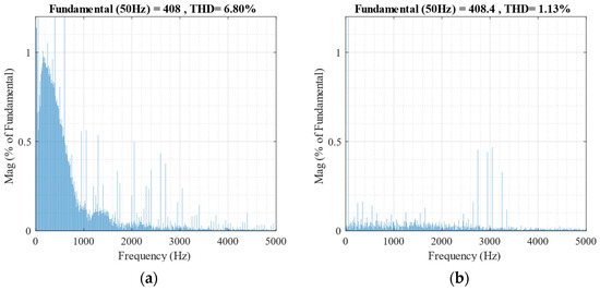
Figure 12.
Harmonic distortion analysis of the output current: (a) not balanced; (b) balanced.
To compare the control performance of the HASBC and the SASBC, the SoC profiles under the two control methods are shown separately in Figure 13a,b in terms of phase SoC, arm SoC, and individual SoC. It is noted that the arm SoC profiles with the HASBC cannot be converged to a line, and the individual SoC profiles of phase A split as two bundles, even though the individual SoC profiles of phase B and phase C are well equalized. In contrast, the arm SoC profiles with the SASBC tend to be equal, and the individual SoC profiles of phase A, phase B, and phase C are all well balanced. The SoC profiles are shown in 5 s for the sake of a clear illustration, and more information is shown in Figure 14.
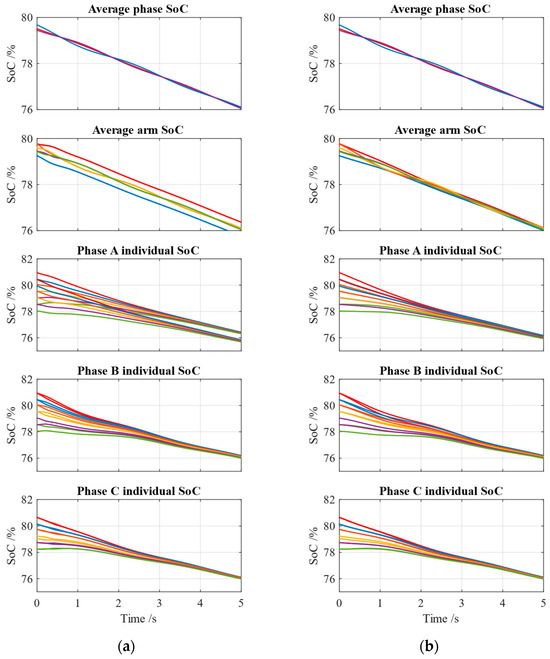
Figure 13.
SoC profiles: (a) with HASBC; (b) with SASBC.
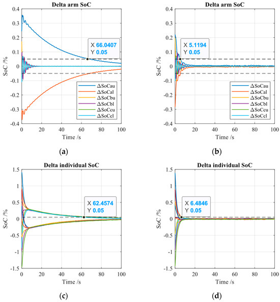
Figure 14.
Convergence comparison of SoC profiles: (a) delta arm SoC with HASBC; (b) delta arm SoC with SASBC; (c) delta individual SoC with HASBC; (d) delta individual SoC with SASBC.
Figure 14 compares the hard SoC balancing control and the soft SoC balancing control further based on processed SoC data given by the following:
Figure 14a,b track the value of the difference/delta between the arm SoCs and their average SoC under the regulation of the hard and soft SoC balancing controls. As shown in Figure 14a, under HASBC, even though the delta arm SoCs in phase B and phase C can be fast-forced to zero, i.e., equalized arm SoCs, the arm SoCs of the phase A upper arm and lower arm are not able to follow the average arm SoC before 100 s, and it takes 66 s in the phase A upper arm to reduce the delta SoC to 0.05% () with reference to the average arm SoC. In contrast, as shown in Figure 14b, all arm SoCs in the three phases/six arms can be balanced fast, and it takes 5.1 s to fall into the 0.05% zone under the SASBC. Figure 14c,d depict the SoC gap (delta individual SoC calculated by Equation (43)) in phase A under the two control modes. It is obvious that the delta individual SoCs under the HASBC are split into two groups and converge slowly (>100 s) toward zero, taking up to 62.5 s to enter the threshold of 0.05% deviation. However, they are forced to converge at zero rapidly and only take 6.5 s to reach the margin of 0.05% under the SASBC. To summarize, the SoC comparison between the HASBC and SASBC is listed in Table 2 based on Figure 13 and Figure 14.
Table 2.
SoC comparison between SASBC and HASBC.
Figure 15 depicts the SoC profiles of 36 submodules of the MMC-BESS model with the SASBC in both the charging and discharging modes. In Figure 15a, the operation starts in the charging mode and then switches to the discharging mode at 10 s. On the contrary, the operation is shifted from the discharging mode to the charging mode at 10 s in Figure 15b. In both scenarios, it is indicated that all the individual SoCs can be forced to converge on a common average value in the charging mode and the discharging mode.
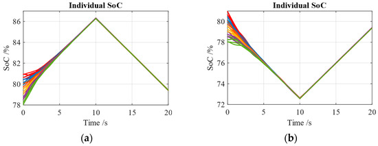
Figure 15.
SoC profiles: (a) from the charging mode to the discharging mode; (b) from the discharging mode to the charging mode.
Considering the robustness of the MMC-BESS, which encompasses numerous submodules and components, evaluating its robustness in response to component variations becomes essential. Consequently, a simulation is conducted for the MMC-BESS, integrating variations in submodule capacitances and arm inductance. The capacitance of the submodule and the inductance of the arm inductor, respectively, exhibit random variations of ±10% around the nominal values. The simulation results, as shown in Figure 16, reveal that the output current, upper and lower arm current, and SoC profiles show little difference from those of the simulation without component variations. Additionally, the circulating current is noticeably higher but acceptable (<2% output current) compared to simulations without these variations. The robustness test shows the control system’s effective performance in handling component variations.
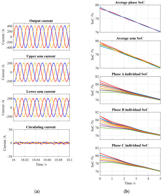
Figure 16.
Simulation results under component variations: (a) arm current and circulating current; (b) SoC profiles.
5. Conclusions
The control of a grid-connected MMC-BESS can have three main parts, which are the grid-connected power control, the circulating current control, and the SoC balancing control. This paper focuses on the modeling and control of a grid-connected MMC-BESS, especially its SoC balancing modeling and control. The main contribution of this paper is the first proposal of the alternative SASBC method compared to the corresponding HASBC. The simulation results show the following:
- Compared to HASBC, SASBC provides better performance in balancing the SoC between and within the arms. In this case, under the control of HASBC, the arm SoCs of the phase A upper arm and lower arm are not able to be equalized before 100 s, and it takes 66 s to reduce the delta SoC to 0.05% with reference to the average arm SoC. In contrast, all the arm SoCs in the three phases/six arms can be balanced fast, and it takes 5.1 s to fall into the 0.05% zone under the control of SASBC. Besides, individual SoCs of phase A under the control of HASBC are split into two groups and exhibit a protracted convergence exceeding 100 s toward zero, requiring 62.5 s to reach the 0.05% deviation range. However, they are forced to converge at zero rapidly and only take 6.5 s to reach the margin of 0.05% under the SASBC.
- The MMC-BESS power fluctuates between phases, arms, and individual submodules to balance the SoC of batteries, and after the accomplishment of the SoC equalization, the power is equally distributed and the circulating current is well eliminated.
- The MMC-BESS can operate in both charging and discharging modes, and the THD of the output current is reduced from 6.80% to 1.13% after SoC balancing is achieved.
- The robustness test shows the control system’s effective performance in handling component variations.
Author Contributions
Conceptualization, Y.W., S.C. and O.H.; methodology, Y.W.; investigation, Y.W., T.G. and O.H.; writing—original draft, Y.W.; writing—review and editing, S.C., T.G. and O.H.; supervision, T.G. and O.H.; funding acquisition, O.H. All authors have read and agreed to the published version of the manuscript.
Funding
This research was sponsored by the China Scholarship Council (Grant No. 201908500121). This project (SiC4Grid) has received funding from the European Union’s Horizon Europe Research and Innovation Programme under Grant Agreement No. 101075496.
Data Availability Statement
Data is contained within the article.
Acknowledgments
The authors acknowledge China Scholarship Council (CSC grant) for sponsoring this Ph.D. research. The authors acknowledge all the project partners involved in the SiC4Grid project. The authors also acknowledge Flanders Make for the support to our research group.
Conflicts of Interest
The authors declare no conflicts of interest.
Appendix A. Derivation of Equations
Appendix A.1. Equation (30)
Appendix A.2. Equation (31)
References
- Market Strategy Board. Grid Integration of Large-Capacity Renewable Energy Sources and Use of Large-Capacity Electrical Energy Storage. Available online: https://webstore.ansi.org/Documents/Grid-integration-Large-Capacity-Renewable-Energy.pdf (accessed on 15 June 2023).
- Mahmoud, A.A.; Hafez, A.A.; Yousef, A.M. Modular Multilevel Converters for Renewable Energies Interfacing: Comparative Review. In Proceedings of the 2019 IEEE Conference on Power Electronics and Renewable Energy (CPERE), Aswan City, Egypt, 23–25 October 2019; pp. 397–406. [Google Scholar]
- Nami, A.; Zare, F. Multilevel Converters in Renewable Energy Systems. In Renew Energy; IntechOpen: London, UK, 2009. [Google Scholar] [CrossRef][Green Version]
- Soong, T.; Lehn, P.W. Evaluation of Emerging Modular Multilevel Converters for BESS Applications. IEEE Trans. Power Deliv. 2014, 29, 2086–2094. [Google Scholar] [CrossRef]
- Wang, Y.; Aksoz, A.; Geury, T.; El Baghdadi, M. Omar Hegazy Performance Enhancement of a Battery-Grid Connected SiC MMC for DC Microgrid Systems. In Proceedings of the 2021 Sixteenth International Conference on Ecological Vehicles and Renewable Energies (EVER), Monte-Carlo, Monaco, 5–7 May 2021; pp. 1–6. [Google Scholar]
- Lesnicar, A.; Marquardt, R. An Innovative Modular Multilevel Converter Topology Suitable for a Wide Power Range. In Proceedings of the 2003 IEEE Bologna Power Tech Conference Proceedings, Bologna, Italy, 23–26 June 2003; Volume 3, pp. 272–277. [Google Scholar]
- Wang, Y.; Aksoz, A.; Geury, T.; Ozturk, S.B.; Kivanc, O.C.; Hegazy, O. A Review of Modular Multilevel Converters for Stationary Applications. Appl. Sci. 2020, 10, 7719. [Google Scholar] [CrossRef]
- Ma, Z.; Jia, M.; Koltermann, L.; Blömeke, A.; De Doncker, R.W.; Li, W.; Sauer, D.U. Review on Grid-Tied Modular Battery Energy Storage Systems: Configuration Classifications, Control Advances, and Performance Evaluations. J. Energy Storage 2023, 74, 109272. [Google Scholar] [CrossRef]
- Shen, K.; Xiao, B.; Mei, J.; Tolbert, L.M.; Wang, J.; Cai, X.; Ji, Y. A Modulation Reconfiguration Based Fault-Tolerant Control Scheme for Modular Multilevel Converters. In Proceedings of the 2013 Twenty-Eighth Annual IEEE Applied Power Electronics Conference and Exposition (APEC), Long Beach, CA, USA, 17–21 March 2013; pp. 3251–3255. [Google Scholar]
- Zheng, Z.; Wang, K.; Xu, L.; Li, Y. A Hybrid Cascaded Multilevel Converter for Battery Energy Management Applied in Electric Vehicles. IEEE Trans. Power Electron. 2014, 29, 3537–3546. [Google Scholar] [CrossRef]
- Liang, G.; Tafti, H.D.; Farivar, G.G.; Pou, J.; Townsend, C.D.; Konstantinou, G.; Ceballos, S. Analytical Derivation of Intersubmodule Active Power Disparity Limits in Modular Multilevel Converter-Based Battery Energy Storage Systems. IEEE Trans. Power Electron. 2021, 36, 2864–2874. [Google Scholar] [CrossRef]
- Mashayekh, A.; Kersten, A.; Kuder, M.; Estaller, J.; Khorasani, M.; Buberger, J.; Eckerle, R.; Weyh, T. Proactive SoC Balancing Strategy for Battery Modular Multilevel Management (BM3) Converter Systems and Reconfigurable Batteries. In Proceedings of the 2021 23rd European Conference on Power Electronics and Applications, EPE 2021 ECCE Europe, Virtual, 6–10 September 2021. [Google Scholar]
- Omar, A.; Wood, A.; Laird, H.; Gaynor, P. Simplified SOC Balancing of an MMC with Embedded Storage in an EV System. In Proceedings of the TENCON 2021—2021 IEEE Region 10 Conference (TENCON), Auckland, New Zealand, 7–10 December 2021; Volume 2021, pp. 929–934. [Google Scholar]
- Mukherjee, N.; De, D. A New State-of-Charge Control Derivation Method for Hybrid Battery Type Integration. IEEE Trans. Energy Convers. 2017, 32, 866–875. [Google Scholar] [CrossRef]
- Maharjan, L.; Inoue, S.; Akagi, H.; Asakura, J. State-of-Charge (SOC)-Balancing Control of a Battery Energy Storage System Based on a Cascade PWM Converter. IEEE Trans. Power Electron. 2009, 24, 1628–1636. [Google Scholar] [CrossRef]
- Lachichi, A. Modular Multilevel Converters with Integrated Batteries Energy Storage. In Proceedings of the 2014 International Conference on Renewable Energy Research and Application (ICRERA), Milwaukee, WI, USA, 19–22 October 2014; pp. 828–832. [Google Scholar]
- Hatano, N.; Ise, T. Control Scheme of Cascaded H-Bridge STATCOM Using Zero-Sequence Voltage and Negative-Sequence Current. IEEE Trans. Power Deliv. 2010, 25, 543–550. [Google Scholar] [CrossRef]
- Li, N.; Gao, F.; Shang, X.; Jia, H.; Li, S.; Guo, B.; Hou, K.; Zhao, X. Operation Principles of Modular Multilevel Conversion System for Electric Vehicles. In Proceedings of the 2020 5th Asia Conference on Power and Electrical Engineering, ACPEE 2020, Chengdu, China, 4–7 June 2020; pp. 1199–1203. [Google Scholar] [CrossRef]
- Quraan, M.; Yeo, T.; Tricoli, P. Design and Control of Modular Multilevel Converters for Battery Electric Vehicles. IEEE Trans. Power Electron. 2016, 31, 507–517. [Google Scholar] [CrossRef]
- D’Arco, S.; Quraan, M.; Tricoli, P.; Piegari, L. Low Frequency Operation of Modular Multilevel Converters with Embedded Battery Cells for Traction Drives. In Proceedings of the 2016 International Symposium on Power Electronics, Electrical Drives, Automation and Motion (SPEEDAM), Capri, Italy, 22–24 June 2016; pp. 1375–1382. [Google Scholar]
- Cai, W.; Hu, P.; Jiang, D.; Liang, Y. An MMC Based Hybrid Energy Storage System: Concept, Topology, and Control. In Proceedings of the 2020 IEEE Student Conference on Electric Machines and Systems, SCEMS 2020, Jinan, China, 4–6 December 2020; pp. 680–685. [Google Scholar]
- Luo, H.; Xu, C.; Dai, K.; Cheng, C.; Huang, Y.; Pan, F. Balance Control of SOC for MMC-BESS With Power Fluctuation Suppression, PCC Voltage Regulation, and Harmonic Mitigation in Grid-Connected Wind Farm. IEEE Access 2022, 10, 117732–117744. [Google Scholar] [CrossRef]
- Li, N.; Gao, F. Linearized Operation of MMC Battery Energy Storage System. In Proceedings of the 2016 IEEE 2nd Annual Southern Power Electronics Conference (SPEC), Auckland, New Zealand, 5–8 December 2016; pp. 1–5. [Google Scholar]
- Vasiladiotis, M.; Rufer, A. Analysis and Control of Modular Multilevel Converters with Integrated Battery Energy Storage. IEEE Trans. Power Electron. 2015, 30, 163–175. [Google Scholar] [CrossRef]
- Chen, Q.; Li, R.; Cai, X. Analysis and Fault Control of Hybrid Modular Multilevel Converter with Integrated Battery Energy Storage System. IEEE J. Emerg. Sel. Top. Power Electron. 2017, 5, 64–78. [Google Scholar] [CrossRef]
- Liu, C.; Cai, X.; Chen, Q. Self-Adaptation Control of Second-Life Battery Energy Storage System Based on Cascaded H-Bridge Converter. IEEE J. Emerg. Sel. Top. Power Electron. 2020, 8, 1428–1441. [Google Scholar] [CrossRef]
- Ma, Y.; Lin, H.; Wang, Z.; Ze, Z. Modified State-of-Charge Balancing Control of Modular Multilevel Converter with Integrated Battery Energy Storage System. Energies 2018, 12, 96. [Google Scholar] [CrossRef]
- Ma, Y.; Lin, H.; Wang, Z.; Wang, T. Capacitor Voltage Balancing Control of Modular Multilevel Converters with Energy Storage System by Using Carrier Phase-Shifted Modulation. In Proceedings of the 2017 IEEE Applied Power Electronics Conference and Exposition (APEC), Tampa, FL, USA, 26–30 March 2017; pp. 1821–1828. [Google Scholar]
- Wang, Y.; Chakraborty, S.; Tran, D.D.; Geury, T.; Hegazy, O. Design and Optimization of the Arm Inductor for Modular Multilevel Converter. In Proceedings of the 2022 International Symposium on Power Electronics, Electrical Drives, Automation and Motion, SPEEDAM 2022, Sorrento, Italy, 22–24 June 2022; pp. 354–359. [Google Scholar]
- An, Q.; Zhang, J.; An, Q.; Shamekov, A. Quasi-Proportional-Resonant Controller Based Adaptive Position Observer for Sensorless Control of PMSM Drives Under Low Carrier Ratio. IEEE Trans. Ind. Electron. 2020, 67, 2564–2573. [Google Scholar] [CrossRef]
- Qiu, J.; Hang, L.; Liu, D.; Geng, S.; Ma, X.; Li, Z. Novel Method for Circulating Current Suppression in MMCs Based on Multiple Quasi-PR Controller. In Proceedings of the 2016 IEEE Applied Power Electronics Conference and Exposition (APEC), Long Beach, CA, USA, 20–24 March 2016; Volume 18, pp. 3560–3565. [Google Scholar]
- She, X.; Huang, A.; Ni, X.; Burgos, R. AC Circulating Currents Suppression in Modular Multilevel Converter. In Proceedings of the IECON Proceedings (Industrial Electronics Conference), Montreal, QC, Canada, 25–28 October 2012; pp. 191–196. [Google Scholar] [CrossRef]
- Ye, T.; Dai, N.; Lam, C.-S.; Wong, M.-C.; Guerrero, J.M. Analysis, Design, and Implementation of a Quasi-Proportional-Resonant Controller for a Multifunctional Capacitive-Coupling Grid-Connected Inverter. IEEE Trans. Ind. Appl. 2016, 52, 4269–4280. [Google Scholar] [CrossRef]
- Parikh, H.R.; Martin-loeches, R.S. Control of Modular Multilevel Converter(MMC) Based HVDC Application under Unbalanced Conditions. Master’s Thesis, Aalborg University, Aalborg, Denmark, 2016. Available online: https://projekter.aau.dk/projekter/files/239473549/PED4_940.pdf (accessed on 25 September 2021).
- Holmes, D.G.; Lipo, T.A.; McGrath, B.P.; Kong, W.Y. Optimized Design of Stationary Frame Three Phase AC Current Regulators. IEEE Trans. Power Electron. 2009, 24, 2417–2426. [Google Scholar] [CrossRef]
- Kolb, J.; Kammerer, F.; Braun, M. Dimensioning and Design of a Modular Multilevel Converter for Drive Applications. In Proceedings of the 15th International Power Electronics and Motion Control Conference and Exposition, EPE-PEMC 2012 ECCE Europe, Novi Sad, Serbia, 4–6 September 2012. [Google Scholar]
Disclaimer/Publisher’s Note: The statements, opinions and data contained in all publications are solely those of the individual author(s) and contributor(s) and not of MDPI and/or the editor(s). MDPI and/or the editor(s) disclaim responsibility for any injury to people or property resulting from any ideas, methods, instructions or products referred to in the content. |
© 2024 by the authors. Licensee MDPI, Basel, Switzerland. This article is an open access article distributed under the terms and conditions of the Creative Commons Attribution (CC BY) license (https://creativecommons.org/licenses/by/4.0/).