Abstract
In the energy transition from fossil fuels to renewables, the tendency is to benefit from ultra-sour natural gas reserves, whose monetization was previously considered unviable. The increasing H2S content together with the growing concern about emissions that are harmful to the environment, make necessary the development of efficient strategies for pollutants management. Although large-scale H2S conversion is well-established through the Claus process, novel technologies for H2S valorization could be a reliable alternative for waste-to-valuable chemicals, following the circular economy. In this perspective, technologies such as Hydrogen Sulfide Methane Reformation (H2SMR), non-thermal plasma, photocatalytic decomposition, decomposition through cycles and electrolysis are analyzed for the H2 production from H2S. They represent promising alternatives for the simultaneous H2S valorization and H2 production, without direct CO2 emissions, as opposite to the traditional methane steam reforming. The various H2S conversion routes to H2 are examined, highlighting the advantages and disadvantages of each of them. This review focuses in particular on the most promising technologies, the H2SMR and the non-thermal plasma, for which preliminary process scheme and techno-economic analysis are also reported. Finally, the major research gaps and future developments necessary to unlock the full potential of hydrogen sulfide valorization as a sustainable pathway for hydrogen production are discussed.
1. Introduction
Global energy demand is expected to grow in the coming years. Therefore, to satisfy the growing natural gas demand, the exploitation of sour and ultra-sour natural gas reservoirs, which was previously deemed unprofitable [1,2], should be considered. The high acid and sour gas content of these types of raw gases must be lowered to meet commercial natural gas specifications [3,4,5]. Waste-to-chemicals technologies are gaining attention because of growing concerns about emissions and of the widespread diffusion of circular economy concepts [6,7].
In the natural gas treatment chain, hydrogen sulfide is a hazardous component that must be removed and post-treated [8,9]. H2S, together with CO2, is usually removed in an amine absorption and regeneration unit. The hydrogen sulfide-rich stream, separated from the natural gas, is then processed in the Claus sulfur recovery unit [10], where the hydrogen sulfide is oxidized to elemental sulfur (reactions (1) and (2)).
In reactions (1) and (2), hydrogen present in H2S molecule is converted into water vapor. Together with H2O, SO2 is generated to ensure sulfur production. In principle, it would be advantageous to exploit H2S by recovering its intrinsic hydrogen content, with the production of a high added value compound.
To date, steam methane reforming (SMR) is the reference catalytic process for H2 production. The high CO2 associated emissions, both direct and indirect, are the main drawbacks of methane reforming: for a given mole of CH4, one mole of CO2 is emitted directly from the reaction (3), in addition to the indirect CO2 emitted to provide the required reaction heat (4). Therefore, the COx generation inside the process makes SMR a non-environmentally friendly production of H2 [11].
The conversion of H2S to H2 offers several advantages [6]. Firstly, it presents an opportunity to mitigate the environmental and health hazards associated with H2S emissions. By transforming this hazardous compound into a valuable energy carrier like hydrogen, not only can environmental pollution be reduced, but also economic benefits can be achieved through the utilization of a previously wasted resource. Moreover, hydrogen, as a versatile energy vector, can be stored, transported, and utilized in a wide range of applications, including fuel cells, chemical synthesis, and industrial processes [12,13,14,15].
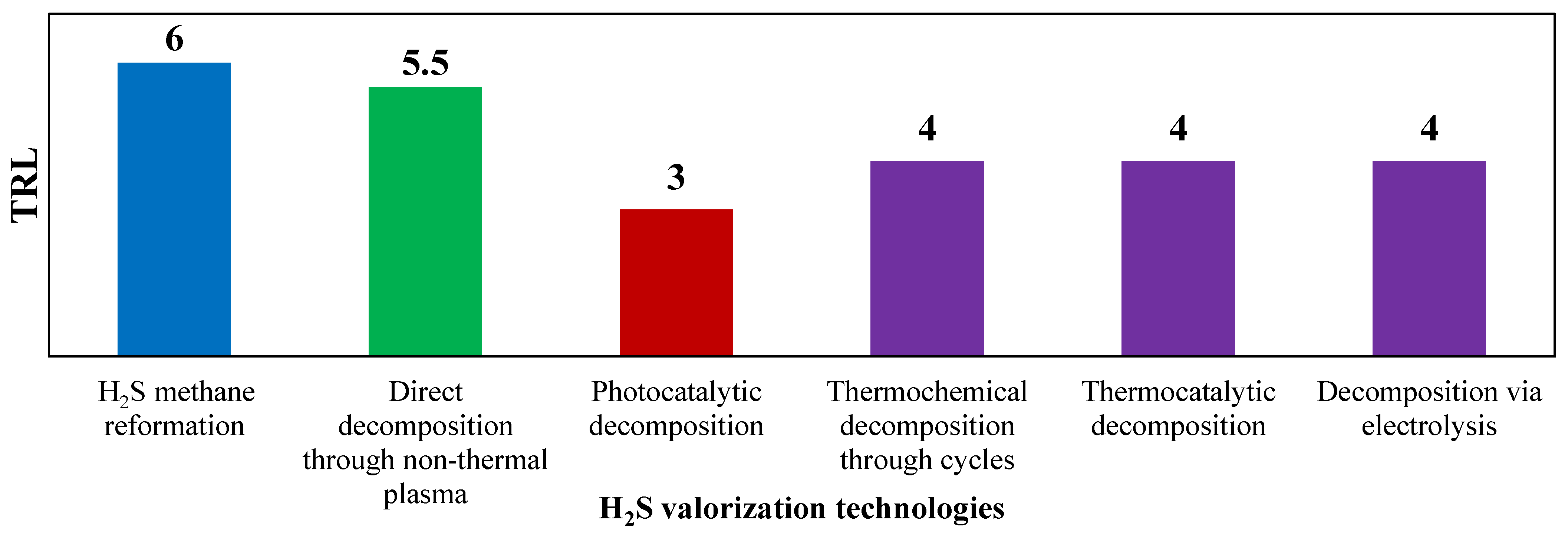
This comprehensive review aims to provide a state-of-the-art analysis of the technologies available for hydrogen sulfide valorization to hydrogen. A classification of these technologies based on technology readiness level (TRL) is shown in Figure 1.
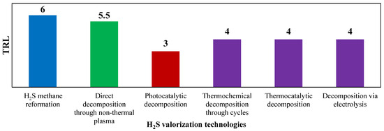
Figure 1.
TRL of technologies for H2S valorization. Reproduced with permission from [16], Elsevier, 2024.
TRL is a systematic metric used to assess the maturity and readiness of a technology. It is used as an evaluation standard in this work since it provides a way to evaluate the progress of a technology from its early concept to its practical application. The TRL scale typically ranges from 1 to 9, with each level representing a different stage in the development and readiness of a technology. Among the available H2S to H2 valorization technologies, the hydrogen sulfide methane reformation (H2SMR) is the one with the highest TRL value, ready for commercial-scale implementation, as the process shares similarities with SMR and does not require special equipment. Decomposition using non-thermal plasma stands as the second most developed technology for decomposing H2S to H2. This technology has a TRL equal to 5–6. However, its unconventional equipment needs further testing to verify its scalability and lifetime. Also, the reaction mechanism remains not fully understood, necessitating a thorough kinetic analysis to understand how operating conditions and feed mixture composition can affect the process [17]. The photocatalytic decomposition technology, which presents a low TRL (equal to 3), and requires in-depth research at the laboratory scale, before the process can potentially reach commercialization level [18]. Thermochemical decomposition via metal or metal sulfides cycles presents a very complex reacting system, due to the difficult separations downstream the reactor, hindering the technology scale-up [19]. H2S thermocatalytic decomposition, involving catalyst use to lower reaction temperatures and allowing the presence of O2, holds a TRL of 4. Issues related to SO2 formation during oxidative decomposition and catalyst deactivation prevent its industrial scalability at present. The electrolysis-based decomposition process currently faces two main obstacles that hinder its industrialization: electrode passivation and formation of polysulfides in the reaction environment [20].
In the following sections, the various H2S conversion routes to H2 are examined, highlighting their underlying principles, recent developments, and potential applications. The key factors influencing the efficiency and scalability of these processes, such as catalyst design, process optimization, and hydrogen purification techniques, are discussed. This review focuses in particular on the most promising technologies, the H2SMR and the non-thermal plasma, for which preliminary process scheme and techno-economic analysis are also reported. Finally, the major research gaps and future developments necessary to unlock the full potential of hydrogen sulfide valorization as a sustainable pathway for hydrogen production are discussed. Overall, this review aims to serve as a comprehensive resource for researchers, industry professionals, and policymakers seeking to understand the current state of H2S valorization technologies and their role in the transition towards a cleaner and more sustainable energy landscape.
2. Hydrogen Sulfide Methane Reformation
H2S methane reformation process is the most promising alternative for the H2S valorization to H2. According to the H2SMR, hydrogen sulfide is converted to H2 and carbon disulfide (CS2) via reaction (5). Hydrogen holds considerable value due to its versatility and potential as a clean energy carrier, as its combustion does not generate CO2 emissions [21]. As a clean alternative to traditional fuels, hydrogen can be employed in various applications, ranging from fueling vehicles and generating power to serving as a reducing agent in industrial processes. Additionally, hydrogen plays a crucial role in decarbonizing industries like steel and chemical manufacturing, providing a cleaner alternative to carbon-intensive methods. CS2 is a colorless, toxic, and highly flammable chemical [22]. It was first produced in 1880 through the high temperature heating of charcoal together with sulfur. The original process was then replaced by a novel one based on hydrocarbons such as methane, ethane, and ethylene as feedstock. CS2, typically commercialized both in technical and reagent grades (up to 99.9% pure), finds its primary application in producing xanthate for cellulosic materials like rayon and cellophane. Viscose products account for approximately half of the CS2 market. The second main use is in the production of CCl4. Other applications include flotation agents, pesticides, and rubber chemicals [23]. As the demand for carbon disulfide is expected to increase by 2025 [24], due to the growing need for cellophane from the packing industry, carbon disulfide production is getting attention in the industrial processes panorama.
Reaction (5) allows both the hydrogen and carbon disulfide production, enabling the simultaneous H2S abatement and valorization. The duty required by reaction (5) is very high (ΔH0298 K = 232.4 kJ∙mol−1): fuel has to be burnt to supply the duty. No direct CO2 is emitted from the reaction process: only indirect CO2 emissions due to the fuel combustion are present. At high temperature, in the presence of H2S and CH4, side-reactions (6) and (7) can take place. Reaction (7) is one of the main criticalities of the H2SMR process. In fact, if this reaction takes place in the reacting system, the carbon deposit can poison the catalyst and damage the equipment. So, a thorough understanding of the system’s thermodynamics is essential to assess under which conditions carbon lay down is likely to occur.
The first paper in the literature on the chemical equilibrium of CH4 and H2S at high temperatures goes back to the one by Megalofonos et al. in 1991 [25]. Later on, Huang and T-Raissi [26] carried out phase-equilibria calculations to assess how the inlet reactants affect the system. Subsequently, experimental and simulation analyses were carried out to characterize the kinetics of the system and identify the most performing catalyst [27,28,29,30,31,32,33,34,35]. Most of the work is aimed at defining the operation ranges in order to avoid carbon deposition. Indeed, for a successful scale-up of the process, the optimal operating conditions in terms of pressure, temperature, and feed composition must be assessed carefully. The thermodynamic assessment of the reacting mixture is detailed in Section 2.1.
2.1. Thermodynamic Assessment
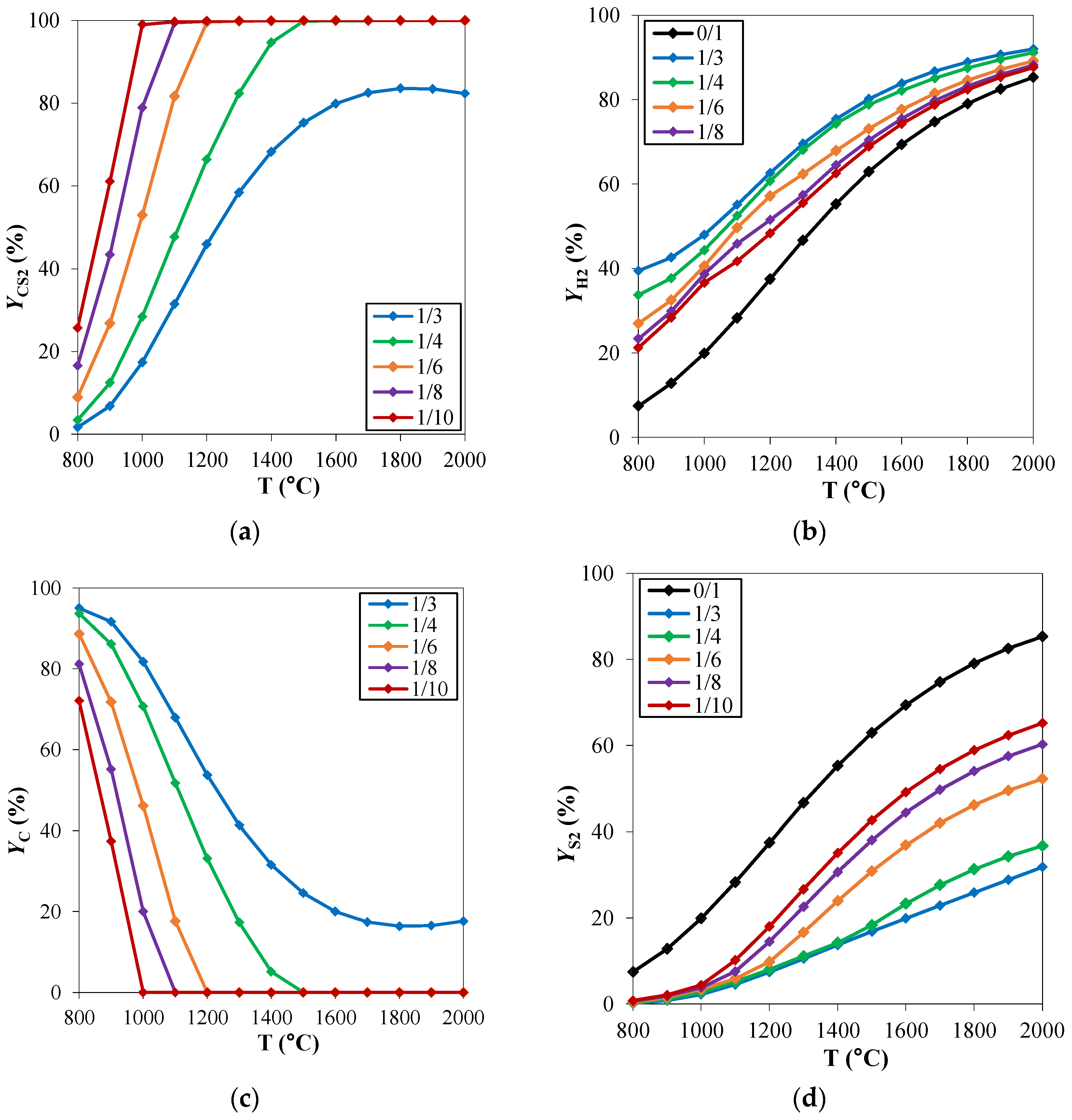
The effect of the operating conditions, mainly temperature and pressure, on the equilibrium of a reacting system can be clarified through the careful assessment of the process thermodynamics. To study the chemical equilibrium of a reacting system, ad hoc developed routines or commercial process simulators can be used. In both cases, the aim is to minimize the Gibbs free energy of the reacting system at a fixed temperature T and pressure P, to evaluate the chemical composition of the system at thermodynamic equilibrium conditions. In the specific case of hydrogen sulfide methane reformation, Spatolisano et al. [16] performed thermochemical equilibrium calculations using the Aspen Plus® V.11 RGibbs module [36]. In this work, the effect of reaction temperature and feed composition on system behavior was first assessed at atmospheric pressure. The investigated temperature range was 800–2000 °C, while the feed composition was varied by varying the CH4/H2S feed molar ratio in the range 1/3–1/10. These ratios were chosen to investigate the potential advantage of having a H2S excess on the solid carbon deposition and were compared with the stoichiometric ratio CH4/H2S of 1/2. The results, reported in Figure 2 in terms of carbon disulfide, hydrogen, carbon, and sulfur yields, are coherent with the study performed by Huang and T-Raissi [26]. At elevated temperatures, CS2, H2, C, and S2 are established as the thermodynamically favored products. The C yield (Yc) decreases when temperature rises at fixed CH4/H2S feed molar ratio. The point at which no carbon deposition takes place is of particular interest for the process operating conditions. The minimum temperature for which the carbon yield is 0 is called “pinch point temperature” in the literature. This temperature is known to decrease when CH4/H2S decreases: in this case, an excess of H2S is available to react with methane such that reaction (5) occurs preferentially rather than reaction (7). As a consequence, the reformation reaction is more favored at high temperatures and low CH4/H2S feed molar ratios, such that the CS2 yield increases in these cases. Furthermore, for the same reasons, a decrease in S yield occurs: H2S reacts preferentially with methane and reaction (5) is more favored than reaction (6) (Figure 2c). According to thermodynamics, it would be advantageous to work with a large H2S excess. However, significant H2S content in the process, higher than the stoichiometric ratio, makes the unreacted gas volume increase, thus increasing the flowrate of the recycle stream. As a consequence, the fixed and operating costs of the purification section downstream the reactor increase in this case. For this reason, in order to identify the optimal reactants feed ratio, a sensitivity analysis must be performed during the process simulation phase with the purpose to minimize the total costs of the process (presented in Section 2.3.2).
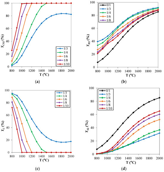
Figure 2.
H2S methane reformation products: yield (Y) of (a) CS2, (b) H2, (c) C and (d) S2 as a function of temperature, for different CH4/H2S feed molar ratios and at fixed pressure of 1 atm. Reproduced with permission from [16], Elsevier, 2024.
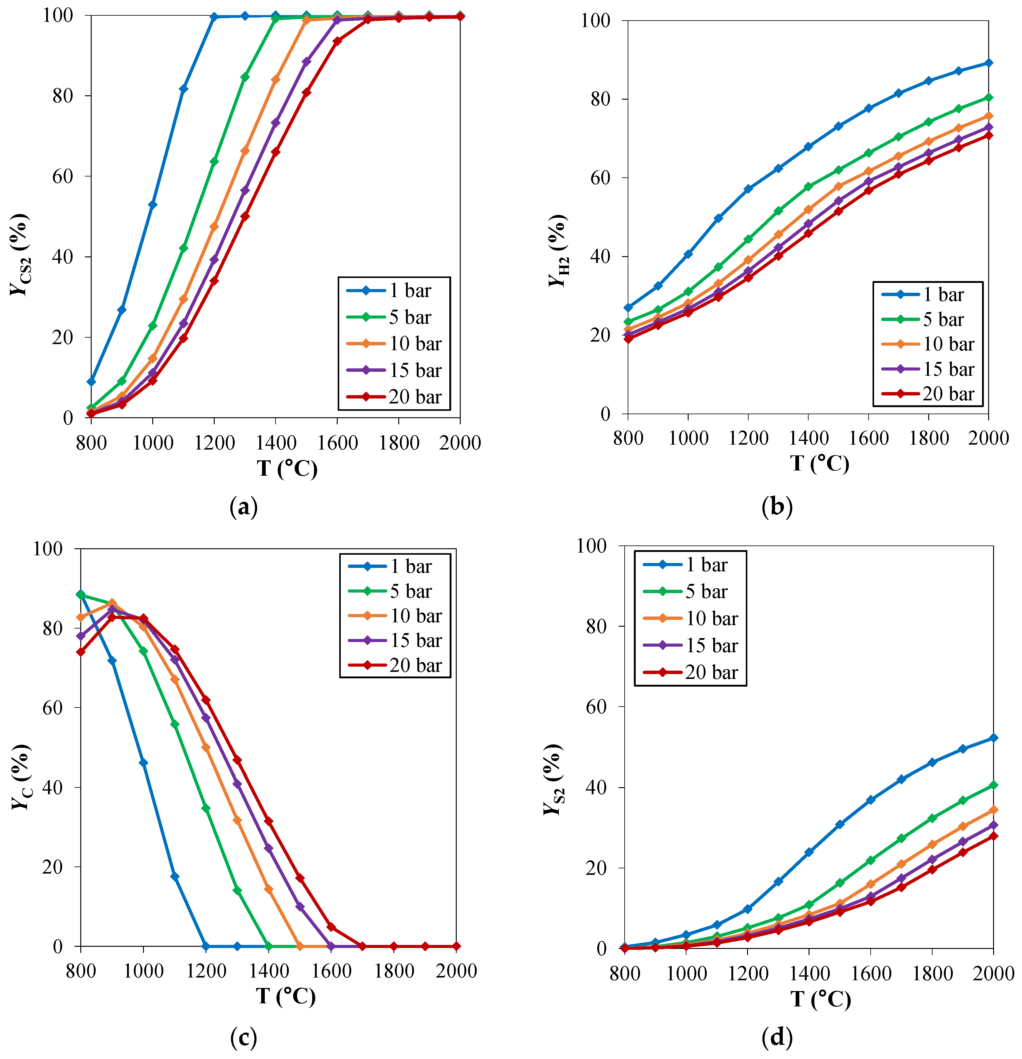
For hydrogen sulfide methane reformation, the same considerations of the traditional steam methane reforming regarding the operating pressures can be applied. High pressure operation can be helpful in reducing the reactor’s volume. Therefore, the analysis of the pressure effect on the reaction thermodynamics can be useful in the assessment of the best operating pressure in the process design phase. The effect of the operating pressure on the chemical equilibrium of the reacting system is reported in Figure 3. The investigated pressure range is 1–20 bar. From the thermodynamic point of view, the H2SMR reaction (reaction (5)) takes place with an increasing number of moles, thus it is favored at low pressures. Indeed, CS2 and H2 yields shown in Figure 3a,b are lower at increasing pressures. When the pressure increases, carbon deposition becomes higher, as depicted in Figure 3d. If, on the one hand, high pressure is advantageous to reduce the reactor’s volume and to favor the kinetics, on the other one, it is not beneficial for the thermodynamics, making the pinch point temperature rise at fixed CH4/H2S feed molar ratio.
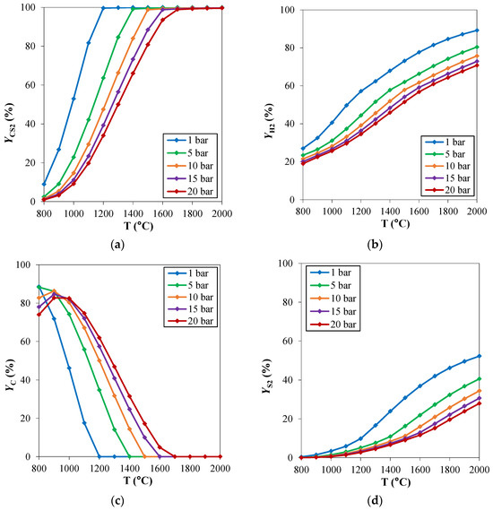
Figure 3.
H2S methane reformation products: yield (Y) of (a) CS2, (b) H2, (c) C and (d) S2 as a function of temperature, for different pressures and at fixed CH4/H2S feed molar ratio of 1/6. Reproduced with permission from [16], Elsevier, 2024.
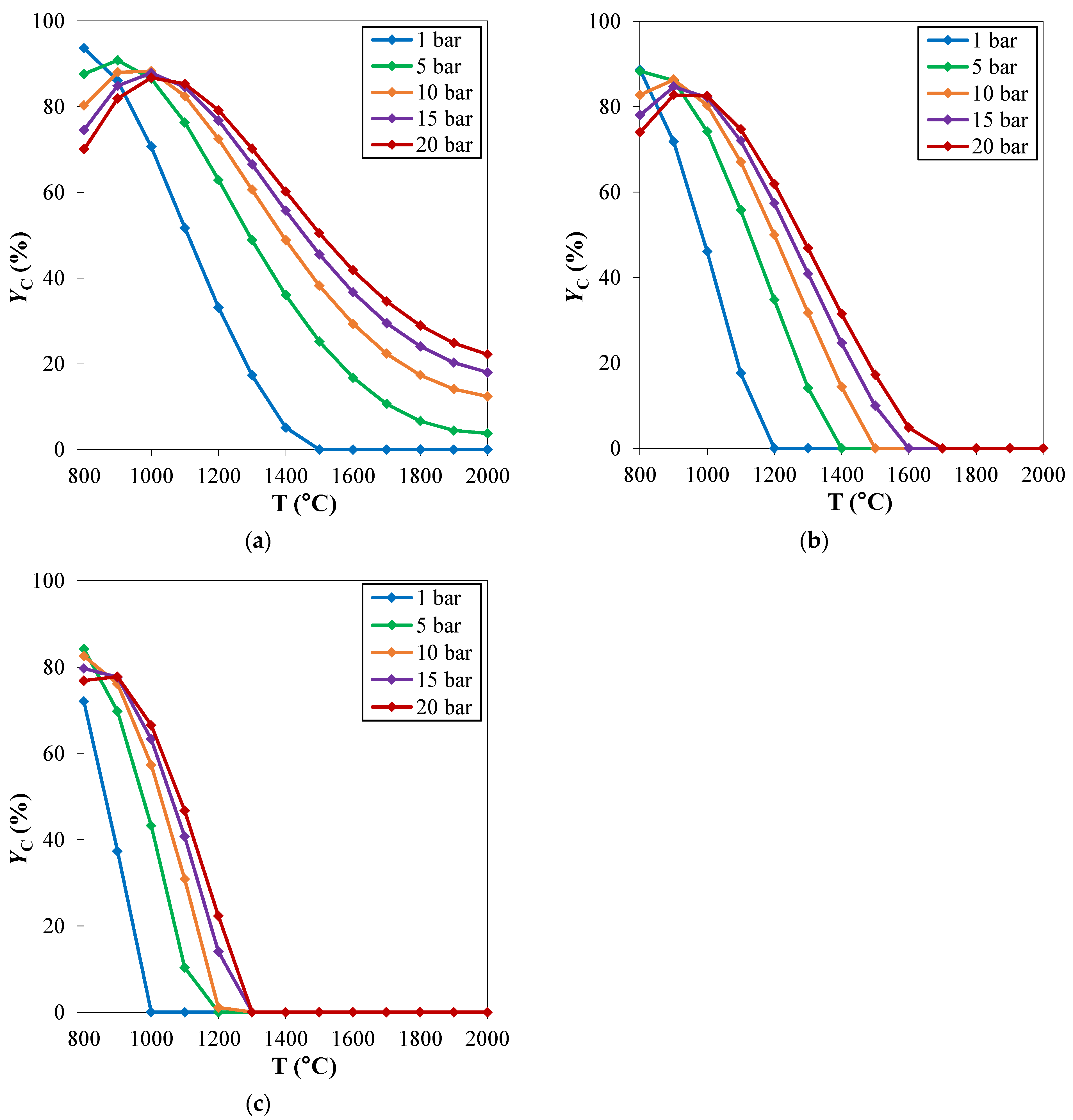
The behavior of the system as a function of pressure qualitatively discussed, is clearly independent on the considered CH4/H2S feed molar ratio (Figure 4). However, the pinch temperature increases with pressure is more significant at high CH4/H2S feed molar ratios.
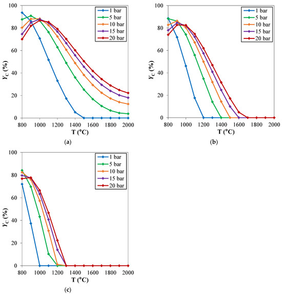
Figure 4.
Carbon yield (YC) as a function of temperature, at different pressures. CH4/H2S feed molar ratio is fixed at: (a) 1/4; (b) 1/6; (c) 1/10. Reproduced with permission from [16], Elsevier, 2024.
To perform a complete assessment of the reacting system thermodynamic behavior, the effect of impurities in the inlet stream is worthy of consideration. As the fed CH4 is likely sourced from a natural gas stream, the presence of water, heavier hydrocarbons (ethane and propane), and CO2 on the chemical equilibrium has to be discussed. The effect of the presence of H2O on the thermodynamics of the system was discussed by Spatolisano et al. [16]. These authors assumed a H2O variable content in the inlet stream ranging from 0 to 7 mol% and concluded that the presence of water causes a decrease in the pinch point temperature. This is an advantage for the process operation, because coke formation can be reduced. Nevertheless, carbon monoxide is co-produced in this case and, if fuel quality H2 is the desired product, it must be separated from H2 downstream the reaction section. Together with water, a small quantity of heavier hydrocarbons (as C2+) may be present in the inlet stream. For the sake of simplicity ethane and propane were selected to represent the heavier hydrocarbon species. Their effect on the system’s thermodynamics was assessed by Spatolisano et al. [16] at variable molar content in the feed, ranging from 0 to 10 mol%. The results showed that the effect of higher hydrocarbons is to increase the pinch temperature (reactions (10) and (11)), but also to increase, in a less significant amount, the hydrogen and carbon disulfide produced, because of the reformation reactions (8) and (9). This evidence was also confirmed by Megalofonos and Papayannakos [25].
When carbon dioxide is also present in the feed stream, CO and COS are coproduced. According to Spatolisano et al. [16], at high CO2 contents, H2 and CS2 production is lower and the same is for carbon deposition. On the other hand, an increase in CO and COS production is observed. Thus, it can be stated that, if carbon dioxide traces can be advantageous to avoid coke formation, at higher CO2 contents in the inlet stream other gaseous species (mainly CO and COS) are coproduced, that can hinder the H2 separation from contaminants downstream the reactor. Generally, impurity content must be tuned according to the market specifications of the product. If fuel quality H2 must be obtained, low H2O, C2+ and CO2 contents can be tolerated. If syngas (H2-CO mixture) is the desired product, higher impurity contents are admissible.
The effect of the presence of sulfur on the reaction thermodynamics is investigated by Tollini et al. [37]. Results show that modifying the S2, H2S, and CH4 inlet composition can optimize the system. This optimization leads to improved H2 yield, decreased C and S2 deposition, enhanced H2S removal efficiency, and reduction in the required thermal duty.
2.2. Catalyst and Kinetic Modelling
Once the thermodynamic framework has been assessed, it is necessary to investigate the kinetics. There are numerous experimental studies conducted at laboratory level, in the presence of a catalyst, in order to identify an optimal formulation for the catalytic species on the one hand, and to clarify the reaction mechanism on the other, thus proposing a model for the kinetic phenomenon. The optimal formulation for the H2SMR catalyst of the reformation process is one of the critical issues for the scale-up of the technology at an industrial level. In general, all proposed catalysts must be designed to withstand severe operating conditions, resulting from high temperatures and a highly corrosive atmosphere due to the high concentrations of H2S.
Megalofonos and Papayannakos [25] conducted experiments using a MoS2 catalytic tubular reactor. The catalyst was tested in a temperature range of 700–800 °C and under a pressure of 1 bar. Results indicated that for residence times less than 5 seconds and reaction temperatures below 790 °C, the percentage of H2 in the gas mixture at the reactor outlet varied between 10% and 25%. This corresponds to 40–80% of the respective equilibrium values. The catalyst exhibited irreversible deactivation, but after 240,000 s in operation, it stabilized at a constant remaining activity level of approximately 50%. The same authors also studied the H2SMR reaction over a Pt/Al2O3 catalyst [27] in a fixed bed tubular reactor in a temperature range of 700–800 °C under 1 bar pressure and for space times between 0.1 and 1 s. Megalofonos and Papayannakos [27,28] employed the Langmuir-Hinshelwood–Hougen–Watson theory to obtain 18 different kinetic models for each of the two investigated catalysts, MoS2 and Pt/Al2O3:
In Equation (12), d = 4, 3, 2 is the number of H atoms in the molecule CHd, depending on the molecular or radical species involved, v is the number of chemisorbed sulfur atoms reacting with CHd and c is the number of participating catalytic sites. The parameters k and Kpi are functions of temperature as follows:
In Equation (13), βwi and βvi are constant parameters. The best kinetic model for each of the investigated catalyst is defined by the values of d, v and c reported in Table 1, where the optimal values of the parameters k and Kpi for each catalyst are also summarized.

Table 1.
Constants of the best kinetic model for each of the investigated catalysts [27,28].
According to the best kinetic model for each catalyst, for MoS2 the rate-controlling step resulted to be the reaction involving the chemisorbed species H2S, CH3 and S on the catalytic surface, with the participation of 3 catalytic sites, while for Pt/Al2O3 it resulted to be the reaction among two chemisorbed S and one CH2 on the catalytic surface, with the participation of 3 catalytic sites.
Martínez-Salazar et al. [32] conducted experiments on a set of supported catalysts utilizing ceramic-type supports (ZrO2-La2O3 and ZrO2-SBA15) and refractory metals (Cr, Mo). The catalytic activity of these materials confirmed elevated H2 yields (64%) within the temperature range of 800–850 °C, with evolution of the initial crystalline phases into a mixture of sulfides (MoS2, ZrS2) and carbides (MoC, Mo3C2) during the reaction, which could be the active phases. The most effective catalysts were those consisting of CrMo/La2O3-ZrO2 and Mo/La2O3-ZrO2. For the latter, Martínez-Salazar et al. [31] calculated the pre-exponential factor A and activation energy Ea of the Arrenhius equation for reactions (5) and (6), whose values are A = 129832.44 mol∙kgcat−1∙h−1 and Ea = 57.91 kJ∙mol−1 and A = 13164.78 mol∙kgcat−1∙h−1 and Ea = 33.3 kJ∙mol−1, respectively.
Mo-based catalysts are among of the most active for hydrodesulfurization in sulfur-containing reaction systems, due to their excellent absorption and resistance to sulfur components [38]. Also, the high melting point of Mo-based species have been shown to be effective in eliminating carbon deposition in dry reforming of methane [39].
The Institute of Gas Technology (IGT) [40] carried out tests on various catalysts to assess their activity toward methane decomposition and the regeneration of surface-accumulated carbon. The results revealed that two catalysts, IGT-MS-103 (Cr2S3) and IGT-MS-105 (Ce2S3), exhibited the highest activity in both inhibiting carbon formation and regenerating after carbon deposition. These catalysts were demonstrated to be active in dissociating H2S, a crucial reaction in the H2SMR reaction pathway. Furthermore, they remained stable above 1000 °C and retained a significant portion of their original surface area (2–5 m2∙g−1). Additionally, these catalysts proved highly effective in promoting the reaction between H2S and the carbon deposits on their surfaces.
More recently, Wang et al. [41] demonstrated that metal oxides of group 4–6 elements, inert in both dry and steam methane reformation, exhibit activity and stability when employed as catalysts for the H2SMR. The key active sites involve sulfur species dynamically bound to metal cations throughout the catalytic process. The observed exchange patterns of H/D isotopes and universal rate inhibition by H2 on representative catalysts suggest that there is a quasi-equilibrium state reached in the processes of H2S decomposition and recombination of surface hydrogen atoms, while the dissociation steps of CH4 are reversible, but do not reach a quasi-equilibrium state. A thorough investigation of the kinetic data and the effect of isotopic substitution reveals that the most likely rate-limiting step shared by all catalysts is the sulfur species-mediated cleavage of C–H bonds. Noteworthy differences exist between 3d and 4d/5d catalysts in terms of the thermodynamic stability of sulfur species.
Table 2 shows the details of the catalysts reported in literature, with the relative operating conditions used for the experimental tests and the observed catalytic activity.

Table 2.
Catalysts used in literature and related operating conditions and activities.
Bifunctional catalysts seem to be the most promising for the reformation process, allowing, on the one hand, to prevent the formation of carbon deposits and, on the other, to promote the conversion of H2S to H2. Operating conditions typically widespread at the laboratory level are:
- Atmospheric pressure;
- (CH4/H2S)IN lower than the stoichiometric ratio;
- T of about 1000 °C;
- Residence time in the reactor t < 1 s.
2.3. Process Scheme and Preliminary Economic Evaluations
Various process schemes have been proposed in the literature for the H2SMR process, with different level of detail. The first work in this respect was the one by Huang and T-Raissi [26] in 2008. The authors discussed three alternatives for liquid H2 production and considered several alternatives for H2 separation from the reaction products (carbon disulfide and sulfur), based on H2 liquefaction or membranes. The flowsheets developed were intended as a preliminary process feasibility study, as a follow up of the thermochemical equilibrium calculation performed. For this reason, details about equipment operating conditions and relating consumptions were not provided. Some years later, Martínez-Salazar et al. [42] carried out a techno-economic evaluation of H2 production through H2SMR. The core of process scheme set-up was the reaction section, a tubular reactor in which the kinetic scheme developed by the same authors elsewhere [31] was implemented. Apart from the reaction section, downstream products separation was not deeply detailed. After the analysis of the available literature, to pave the way for the H2SMR scale-up to the industrial level, Spatolisano et al. developed a more detailed process simulation through Aspen Plus® V.11 software [43]. Their analysis started from the Block Flow Diagram (BFD) of Figure 5, useful to identify the main sections of the plant scheme and to develop the process flow diagram.

Figure 5.
BFD of the H2SMR process. Reproduced with permission from [43], Elsevier, 2024.
In the following, the results of the feasibility study by Spatolisano et al. [43] are reported. The authors performed a process simulation at variable CH4/H2S feed molar ratios in the range 1/10–1/4, to discuss the performance for each investigated case. As both capital and operating expenses were also evaluated for all the process simulations carried out, the output of the work provided the H2 production cost as a function of the reactants’ feed ratio. Despite this study was focused on H2S valorization to H2, CS2 was considered as a valuable by-product of the H2 production reaction.
2.3.1. Process Scheme
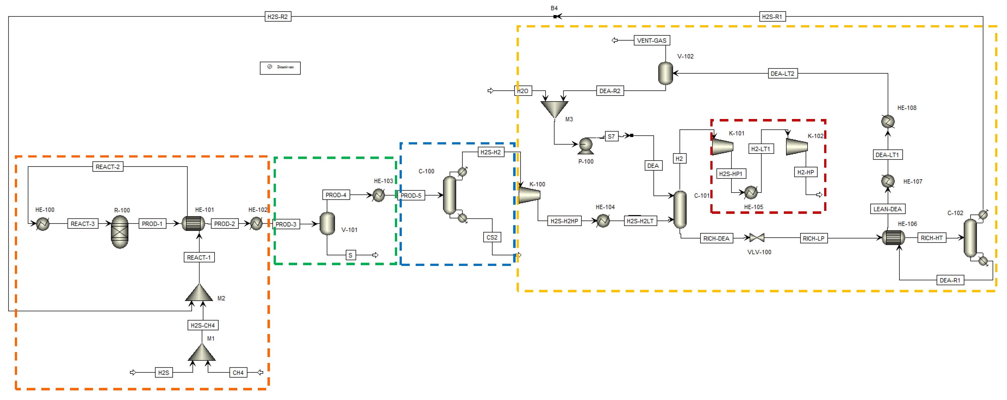
The process flow diagram proposed by Spatolisano et al. [16] for the gaseous hydrogen production is reported in Figure 6 as simulated through Aspen Plus® V.11 [36] commercial software, using the Soave–Redlich–Kwong method to describe the system’s thermodynamics.
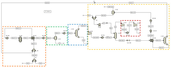
Figure 6.
H2SMR flowsheet as simulated in Aspen Plus® V.11. The sections of the process are highlighted by dashed lines: reaction section, orange; sulfur separation section, green; carbon disulfide separation section, blue; hydrogen sulfide separation section, yellow; hydrogen compression section, red. Reproduced with permission from [43], Elsevier, 2024.
The process flowsheet of Figure 6 receives at its battery limits methane and hydrogen sulfide only, whose ratio was opportunely tuned to perform the process sensitivity analysis. Due to the preliminary level of the process analysis performed, no impurities were considered in the H2S and CH4 streams.
The process flowsheet can be distinguished into different sections:
- Reaction section (dashed orange line in Figure 6). This section mainly consists of the reformation reactor R-100, where reactants reach the thermodynamic equilibrium conversion at the specified pressure and temperature. For each simulated case, fixed the CH4/H2S feed molar ratio, the reaction temperature was set equal to the pinch temperature and the pressure was fixed at 1.7 bar. The fresh H2S and CH4 streams (respectively H2S and CH4 streams in Figure 6) are mixed with the recycled H2S and fed to the reaction section, after being preheated by exchanging heat with the products, in order to recover their high enthalpy content;
- Sulfur separation section (dashed green line in Figure 6). This section mainly consists of the flash V-101, which operates at 135 °C, as both in the Frasch and Claus processes [44]. This separator allows the recovery of a liquid sulfur stream (S in Figure 6) with a purity suitable to be commercialized (>99.5 mol%);
- Carbon disulfide separation section (dashed blue line in Figure 6). This section mainly consists of the C-100 distillation column which allows the CS2 separation as the column bottom product, with a purity >99.5 mol%, such that it can be commercialized. The column top product, a gaseous mixture mainly composed of H2, H2S and traces of CH4, is routed to the hydrogen purification section;
- Hydrogen separation section (dashed yellow line in Figure 6). This section mainly consists of the columns C-101 and C-102. The former is an absorption column, which uses a diethanolamine (DEA) solution at 20 wt.% as the washing solvent to separate the H2 from H2S. H2, exiting from the top of the absorption column, is routed to the H2 compression train, while the rich amine solution, which contains almost all the unconverted H2S, exits from the bottom of the same column and has to be regenerated into the C-102 unit. This latter column performs the separation of hydrogen sulfide from the DEA solution: H2S is recovered as a gaseous product from the top of the column and recycled back to the reaction section, while the DEA solution, exiting from the bottom, is cooled, pumped, and recycled back to the column C-101. The overhead H2S stream contains about 2.5 mol% of water to ensure a sufficiently high operating temperature of the condenser of C-102, such that water can be used as the cooling utility;
All sections but the H2 separation section operate at about atmospheric pressure. The pressure of the hydrogen separation section was set at 10 bar, at a first attempt. However, this operating pressure can be opportunely optimized at a later process development stage. Together with H2 separation section operating pressure, another hint for future process intensification could be the position of the CS2 separation section. In the study of Spatolisano et al. [43], carbon disulfide separation section was located upstream the hydrogen purification section, to lower the flowrate entering the K-100 compressor and, thus, to reduce its energy consumption. This choice has the drawback of lowering the operating temperature of the condenser of column C-100 down to cryogenic levels, because the distillation column C-100 operates at atmospheric pressure. For this reason, the study as to be intended as a preliminary feasibility assessment of H2SMR technology at industrial scale, to pave the way for future optimization. The choice of diethanolamine as solvent is justified by the presence of sulfur-based species, mainly mercaptans and COS, in the stream entering the absorption column C-101. It is known in literature that secondary amines as DEA are less reactive towards these species, such that their presence does not hinder H2S absorption [45]. For the design of the absorption and regeneration columns, however, a more detailed study would be required according to the typical process parameters, such as the rich and lean loading and the thermal load of the regeneration column reboiler. If the final destination of the hydrogen product (H2-HP) is different from the pipeline, a further post-treatment of this stream would be necessary, in principle, to achieve purity levels suitable for industrial applications.
Spatolisano et al. [43] chose an existing Eni S.p.A. Claus plant as a reference to establish the conditions of the inlet streams for the process simulation. This plant receives a fresh acid gas stream and a methane stream (H2S and CH4, respectively, in Figure 6), along with unconverted hydrogen sulfide, recycled from downstream separation sections. The material and energy balances of the process schematized in Figure 6 for each analyzed CH4/H2S feed molar ratio, 1/4, 1/6 and 1/10, are reported in the work by Spatolisano et al. [43]. The flowrate of CH4 entering the process battery limits increases when the CH4 /H2S feed molar ratio is lower due to the higher amount of recycled H2S flowrate. The H2S conversion retrieved for each of the 3 investigated cases, is respectively: 0.6298, 0.3731, and 0.1887. As methane is the limiting reactant in all these cases, its conversion is almost quantitative. Regarding reaction products, the material balances reveal that, when the CH4 /H2S feed molar ratio decreases, the total hydrogen and carbon disulfide molar flowrates increase. However, their purity also decreases (for the sake of example, the stream H2-HP in Figure 6 has a significant amount of CO in the case of CH4/H2S = 1/10). The effect of higher CO impurities at lower CH4 /H2S feed molar ratio can be explained considering the higher H2O amount recycled to the reaction section, along with the unconverted H2S stream. This not negligible H2O amount is responsible for CH4 conversion into CO and H2 through the steam reforming reaction. To limit the water impurity contents in the reaction section, a dehydration stage should be considered when the process is operated at low CH4 /H2S feed molar ratios, before H2S recycle back to the reactor. From the thermal point of view, a decrease in the CH4/H2S feed molar ratio corresponds to a lower pinch point temperature and, thus, to a lower reaction temperature in the RGibbs unit (R-100). However, the reaction duty increases due to the higher amount of circulating flowrates. Downstream of the reactor, the carbon disulfide and hydrogen separation sections show higher energy consumptions with decreasing CH4/H2S feed molar ratio. The heat duties required at both the reboiler and the condenser of columns C-100 and C-102 of Figure 6 are significantly higher. More specifically, when CH4/H2S feed molar ratio is lower, the temperature at the condenser of C-100 is higher due to the higher H2S and lower H2 content in the top product. Moreover, power consumptions are higher when the CH4/H2S feed molar ratio is lower, although these contributions do not significantly impact the overall energy consumption of the process.
2.3.2. Preliminary Economic Evaluations
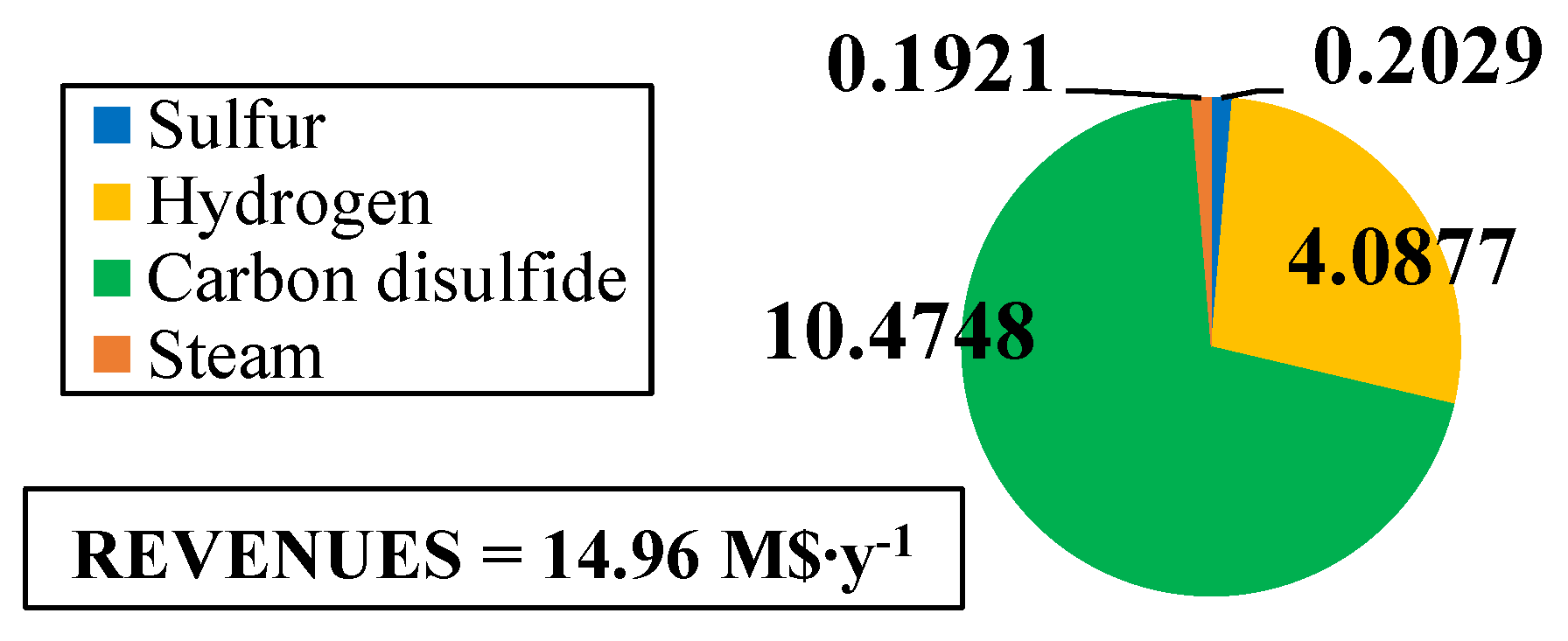
The fixed and operating costs were evaluated in the Spatolisano et al. [43] work in accordance with the Turton methodology [46]. This methodology involves the evaluation of the capital expenses (CAPEX) for each piece of equipment through an ad-hoc cost function, which also considers the operating pressure of the equipment and construction material. Together with CAPEX, also operating costs associated to utilities consumption are evaluated. For each analyzed cases, revenues for products and by-products are assessed. The reference year of the analysis is 2020. Figure 7 reports the results of the economic assessment regarding the capital costs and the utility costs at fixed CH4 /H2S feed molar ratio of 1/4. For the same inlet reactants ration, Figure 8 shows the revenues associated to the H2SMR process. The hydrogen sulfide methane reformation furnace, sized through thermodynamic equilibrium considerations, is the most expensive item: it represents approximately 17% of the overall fixed costs. On the contrary, regarding the utility costs, the most expensive item is the low-pressure steam needed as heating medium. The revenues from the methane reformation process are strongly dependent on the carbon disulfide market, which is produced in substantial quantities and constitutes the primary source of revenue for the process.

Figure 7.
(a) CAPEX (M$) and (b) utility costs (M$∙y−1) for H2S/CH4 = 4. Reproduced with permission from [43], Elsevier, 2024.
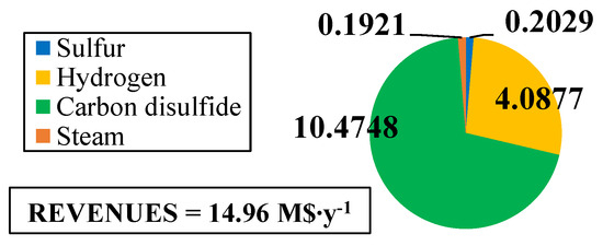
Figure 8.
Revenues (M$∙y−1) for H2S/CH4 = 4. Reproduced with permission from [43], Elsevier, 2024.
The variation in capital expenses compared with the base case (CH4 /H2S feed molar ratio = 1/4) for the other CH4 /H2S feed molar ratios analyzed are detailed in Figure 9. Figure 10 and Figure 11 show the utility costs and revenues variation with respect to the base case, respectively.

Figure 9.
CAPEX variation (M$) compared with the base case for: (a) H2S/CH4 = 6 and (b) H2S/CH4 = 10. Reproduced with permission from [43], Elsevier, 2024.

Figure 10.
Utility costs variation (M$∙y−1) compared with the base case for: (a) H2S/CH4 = 6 and (b) H2S/CH4 = 10. Reproduced with permission from [43], Elsevier, 2024.

Figure 11.
Revenues variation (M$∙y−1) compared with the base case for: (a) H2S/CH4 = 6 and (b) H2S/CH4 = 10. Reproduced with permission from [43], Elsevier, 2024.
The sensitivity analysis performed revealed that fixed costs, as well as all the utility consumption for the fuel and boiler feed water, increase as the CH4/H2S feed molar ratio decreases. This increase is attributed to the larger equipment size required. The decrease in fuel and boiler feed water consumption is due to the decrease in the reaction temperature associated with a lower CH4 /H2S feed molar ratio. Furthermore, revenues increase when CH4 /H2S feed molar ratio decreases. However, as discussed in Section 2.3.1, the increased flowrates of products correspond to a decrease in their purity. This aspect is not negligible at all and has to be considered in the results analysis. A reduction in the CH4/H2S feed molar ratio may necessitate the addition of a further hydrogen purification section or, as an alternative, a dehydration section before H2S recycle to the reactor.
Ali et al. [47] conducted techno-economic and environmental assessments on the viability of H2 production processes involving H2S utilization, such as H2SMR and H2S pyrolysis, as alternatives to SMR, without and with CO2 capture, utilization, and storage (CCUS), and CH4 pyrolysis. From the techno-economic perspective, the high economic value of H2SMR by-products (CS2 and S2) is able to offset the investment costs, resulting in a negative H2 cost of −1.000 USD/kg compared with SMR, SMR with CCUS, and CH4 pyrolysis hydrogen cost of 2.400 USD/kg, 2.410 USD/kg and 1.930 USD/kg, respectively. On the contrary, H2S pyrolysis is less cost effective than H2SMR due to the lower revenue associated with its sole by-product (S2), resulting in hydrogen cost of 3.537 USD/kg, lower than the H2 cost of SMR with CCUS without CO2 sales revenue. From the environmental point of view, H2SMR and H2S pyrolysis demonstrated lower contributions to global warming, qualifying as low-carbon H2 production processes. Although direct CO2 emissions are absent from methane pyrolysis, its classification as low-carbon H2 producer depends on the level of decarbonization of the electricity grid. The authors conclude that transitioning from SMR without and with CCUS to H2SMR for H2 production appears potentially attractive, considering the existing policies for decarbonization.
2.4. Summary and Future Outlooks
The methane reformation process has several advantages and disadvantages, summarized in Table 3. The TRL of this technology, consistently with the guidelines provided by NASA (National Aeronautics and Space Administration) [48], is 6. This process seems feasible for implementation on an industrial level. The perspective of the technology depends, on the one hand, on the energy efficiency of the process itself and, on the other, on the carbon disulfide market. Unlike sulfur or coal, in fact, the outputs on the market of CS2, as it is, are limited. Regarding the energy efficiency of the process, further future insights should cover:

Table 3.
Advantages and disadvantages of the H2S methane reformation process.
- The optimal formulation of the catalyst. Designing the right catalyst for the process is one of the key aspects of technology scale-up. The catalytic activity and the working conditions of the catalyst itself impose limits of operability within which to operate the reformation reaction;
- The kinetics of the system. An in-depth kinetic experimentation could, on the one hand, clarify the phenomenon and produce the experimental observations necessary to model it, on the other hand, identify the most suitable operating conditions for the process, from a not only thermodynamic but also kinetic point of view. In particular, an aspect to be investigated in this sense concerns the effect of pressure on the system. The thermodynamic analysis shows, as expected, that the pressure increase has a negative effect on the balance of the mixture, increasing the production of coke. However, working under pressure could be useful to reduce the reactor size and to facilitate the compression of hydrogen downstream of the reaction, if to be used in pressure applications;
- The optimization of the process scheme, both in the reaction stage, by introducing an appropriate kinetic model, and in the unit operations of downstream separation (separation of CS2 by distillation, H2 separation by absorption).
3. Direct Decomposition through Non-Thermal Plasma
H2S decomposition through non-thermal plasma seems, after the H2S methane reformation process, the second most promising alternative for the H2S valorization to H2, also considering the low dissociation enthalpy of the process (see Equation (14) for the sake of clarity, where ΔH0298 K is lower than the water one, which is ΔH0298 K = 2.96 eV∙molecule−1).
Plasma is a gas that is partially or completely ionized, forming a quasi-neutral state with various components such as electrons, excited molecules and atoms, ions, radicals, neutral gas species, and photons. Although not a thermodynamically stable phase, it is commonly regarded as the 4th state of matter, distinct from the solid, liquid, and vapor phases. Plasma can be broadly categorized into two types: high-temperature and low-temperature plasma. The subcategories of low-temperature plasma include thermal (or quasi-equilibrium) and non-thermal (or non-equilibrium) plasma. Table 4 summarizes this classification.

Table 4.
Classification of plasma. Adapted from [49].
In the non-equilibrium mechanism, the concentration of the end product is influenced by the cooling or quenching rate of the process. Absolute quenching assumes that all stable products are preserved during quenching, with the remaining radicals converting back to the initial substance. Ideal quenching, on the other hand, assumes that all radicals are transformed into products rather than reverting to the initial substance. Even when employing thermodynamic equilibrium modelling (with Chemkin-Pro [50] software) under the ideal quenching assumption, it fails to account for the optimal results observed in experiments involving microwave, radio frequency, and gliding arc plasma discharges. Furthermore, no chemical kinetics model has demonstrated a significant improvement over thermodynamic equilibrium calculations. A plasma-assisted mechanism for low-temperature hydrogen sulfide dissociation has been proposed, wherein non-equilibrium dissociation occurs. Experimental results align well with this assumption, attributed to the transfer of heavy molecules and nuclei of the condensed phase (clusters) from the active zone of the discharge to the periphery.
The typical parameters for assessing the cold plasma dissociation technologies performance are:
- Specific Energy Requirement (SER), SER = W/Qi, being W the input power and Qi the flowrate of the product of interest, which measures the efficiency of the process in terms of the hydrogen production;
- Specific Energy Input (SEI), SEI = W/Q0, being W the input power and Q0 the flowrate of the initial reagent, which measures the efficiency of the process in terms of the inlet H2S conversion.
There are several types of plasma discharges available experimentally: continuous and pulsed direct current (corona or gliding arc), glow, microwave, radiofrequency, atmospheric pressure jet and Dielectric Barrier Discharge (DBD). Gliding arc discharges consist of two flat divergent electrodes with gas flowing between them and they are considered suitable for relatively large gas flows. They can be either thermal or non-thermal, depending on the applied power and gas flowrate. The Gliding Arc Tornado (GAT) introduces a reverse vortex flow to a gliding arc plasma discharge, creating a highly non-equilibrium system with minimal heat losses. GAT ensures uniform treatment of H2S gas in the reactor. Microwave discharges involve using a waveguide to direct microwaves toward the plasma and can operate at low pressure. Since this system does not require electrodes, it has no problem with their lifetime. The DBD setup comprises two electrodes with one or more dielectric barriers in the discharge gap, adaptable to various applications, including the packed-bed DBD reactor, where the gap between parallel electrodes is filled with dielectric pellets. Radio frequency (RF) electromagnetic fields can generate weakly ionized plasma at low pressures (1–103 Pa). Higher pressures result in a discharge approaching a thermal regime. This system is advantageous for applications requiring electrodes to be outside the discharge region, preventing contamination with metal vapors emitted from the electrodes. The two main types of RF discharge are capacitively coupled plasmas (RFC), where radiofrequency power is applied to electrodes, and inductively coupled plasma (RFI), where the field is created using an inductance coil through which radiofrequency current passes.
The process of plasmochemical dissociation of hydrogen sulfide was studied at a laboratory level in microwave plasmatrons of the «Parus» and SV-10 setups in Kurchatov Institute [51]. «Parus» was equipped with a power source in the order of MW, consisting of magnetron oscillators (wavelength of 12.6 cm, frequency of 2.38 GHz, continuous-wave output power of up to 2 kW). The gas flow was between 0.1 and 1 l∙s−1, the working pressure was in the range 0.04–0.2 bar. Results showed relatively low power consumption of the process, (0.8 eV∙molecule−1 in the optimal regime) and a conversion rate up to 85% (at the power consumption of 1.5 eV∙molecule−1). The stating power of the SV-10 plasmatron block was 10 kW (then up to 60 kW) and allowed to work both with microwave plasmatron (magnetron generator of a ~2.40 GHz and discharge power of up to 1.8 kW), RF plasmatron (both RFC and RFI), gliding arc and also with any other source. The results (with RFC using a power of 0.6–2 kW, the flowrate = 150–400 normal cm3∙s−1 at a pressure of 0.08–0.09 bar) showed that the attained minimum size of power inputs was 1 eV∙molecule−1 and the maximum degree of conversion could be close to 100% [52]. Two kinetic mechanisms have been used for modeling the H2S system [53]:
- Mechanism I (Kurchatov Institute in Moscow [51,54]). It involves 9 reversible reactions and 7 species, as reported in Table 5.
 Table 5. Kinetic mechanism proposed by Kurchatov Institute [54,55].
The mechanism is characterized by high activation energy of the two initiating reactions;
- Mechanism II (Binoist et al. [56]), as reported in Table 6. It is an experimentally confirmed mechanism that included additional species, H2S2 and HSS. The mechanism I was amended by the reactions involving H2S2 and HSS.
 Table 6. Kinetic mechanism proposed by Binoist et al. [56]. Reproduced with permission from [56], ACS Publications, 2024.
Ma et al. [57] and Helfritch [58] proposed that the H2S conversion mechanism involves ionization of H2S. In Table 7 the reaction steps involved in the mechanism proposed in the literature are reported [17].

Table 7.
Proposed mechanism of H2S decomposition in non-thermal plasma. Reproduced with permission from [17], Elsevier, 2024.
Nevertheless, both of these mechanisms might not accurately depict the actual process due to the relatively low ionization degree in non-thermal plasmas. Research conducted by Zhao et al. [60] revealed that ionization reactions in non-thermal plasmas are negligible.
The two main industrial setups are at Orenburg and Drogobych. The Orenburg gas processing plant (Gazprom) has nominal power of 1 MW, nominal performance of 1000 m3 of hydrogen per hour (provided by two microwave plasmatrons with a power of up to 500 kW each), radiation at a frequency of 0.9 GHz, pressure of 500 torr (0.67 bar) and the lowest power consumption is about 1.5 kWh per cubic meter of a synthesis gas plus the corresponding amount of sulfur [61]. This experimental-industrial test bench was built to study the dissociation of a H2S/CO2 mixture, in a microwave and high-frequency discharges of a power of several hundred kilowatts [62]. The Drogobych petroleum-refining plant has power up to 50 kW, microwave magnetron at a frequency of 0.915 GHz, pressure of 250 torr (0.33 bar) and rate of the productivity around 50 m3∙h−1 of H2S, which satisfies to plant requirements in the H2S utilization. This pilot apparatuses were constructed and tested under factory conditions (petroleum-refining plants) using technical gas (hydrogen sulfide obtained by the hydrofining of oil from sulfur). The main result of work at Orenburg installation and at Drogobych petroleum-refining plant showed the scalability of the process to the plant conditions keeping the high energy efficiency and confirmed the non-equilibrium mechanism of the of H2S plasma chemical dissociation with a super-ideal quenching [61,63]. The essential conclusions on the study of the plasma chemical treatment of the H2S/CO2 gas are divided into ranges of energy input (SEI) [63]:
- from 0.2 to 0.7 eV∙molecule−1, the process mainly proceeds via the reaction pathway:
The minimum calculated SER is around 1.0 eV∙molecule−1;
- From 0.7 to 1.4 eV∙molecule−1 the process mainly proceeds via the reaction pathway:
The minimum calculated SER is between 1.2 and 1.3 eV∙molecule−1;
- From 1.4 to 4 eV∙molecule−1 the process mainly proceeds via the chemical reaction pathway:
The minimum calculated SER is around 1.6 eV∙molecule−1.
A test-industrial setup employing a microwave plasmatron was organized to follow the reaction pathway (16) and avoid SO2 formation across a broad range of energy input (SEI = 0.3–1.2 eV∙molecule−1), at pressures ranging from 100 to 500 torr (0.13–0.67 bar) [63]. In experiments conducted by Argonne National Laboratory (USA, 1987) using the H2S/CO2 mixture, in a range of SEI between 1.4 and 4 eV∙molecule−1, the observed maximum by-product concentrations were 12% for carbon monoxide and 1.4% for sulfur dioxide (0.6% for CS2 and 0.03% for COS). However, these by-products were not observed in the low-energy cost regime [64].
Considering the analysis of available literature, non-thermal plasma technology appears as the second most promising method, after the H2S methane reformation process, for the H2S valorization to H2. To delve deeper into this technology, a preliminary feasibility study is conducted, detailed in Section 3.1, given the current level of technology maturity.
3.1. Process Scheme and Preliminary Economic Assessment
The starting point of the feasibility study performed is the setup of the process BFD depicted in Figure 12, through which all the process sections can be identified.

Figure 12.
BFD of the H2S to H2 non-thermal plasma decomposition process.
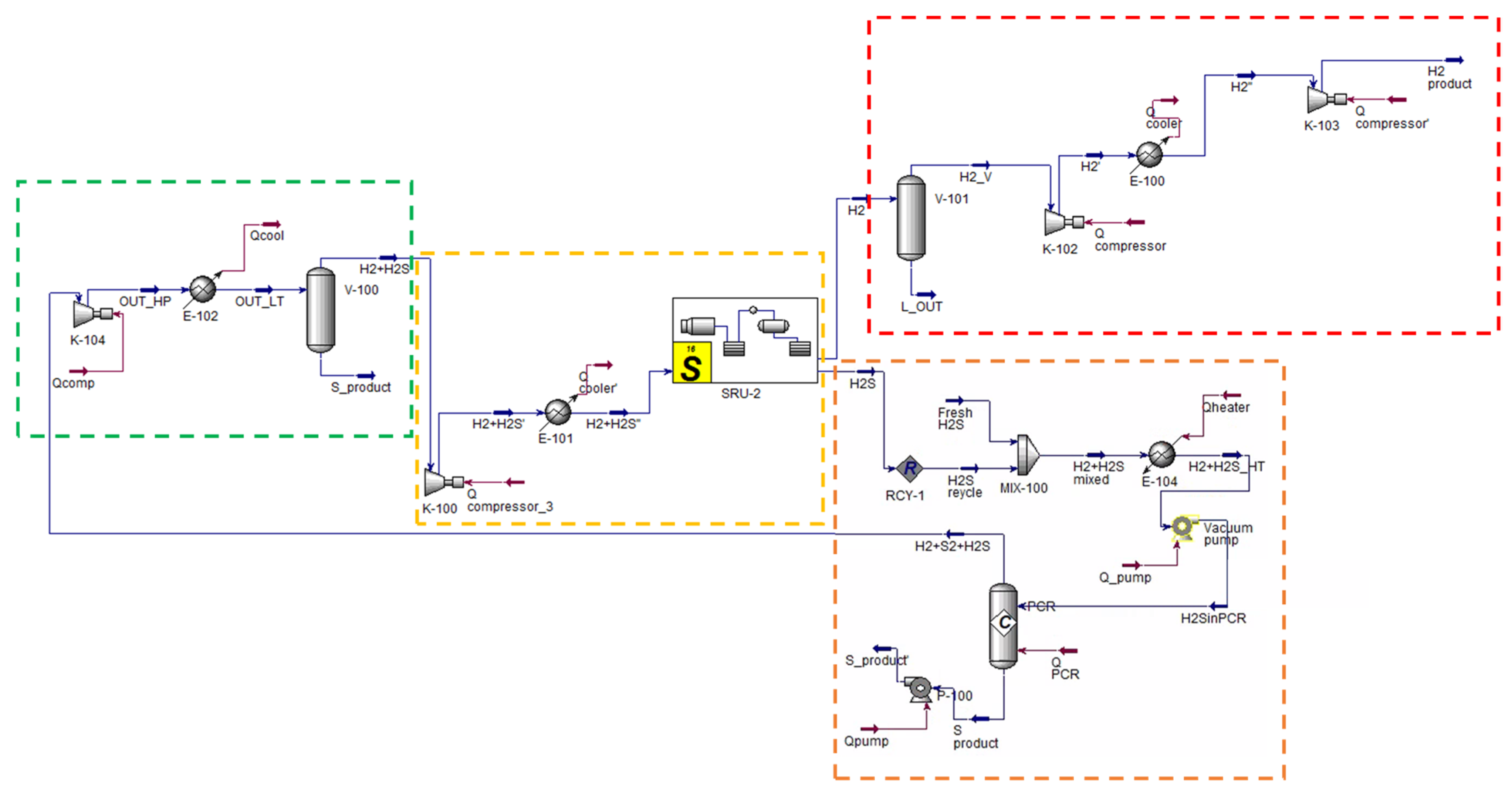
Figure 13 reports the Aspen HYSYS® V.11 simulation of the H2S to H2 non-thermal plasma decomposition. The same Eni S.p.A. Claus plant, already considered in Section 2.3, is taken as reference for the present analysis. Therefore, the same plant size, inlet feed conditions and utility specifications are considered in the process simulation phase. The process scheme can be distinguished into different sections:
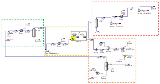
Figure 13.
H2S to H2 non-thermal plasma decomposition process scheme. Simulation in Aspen HYSYS® V.11.
- Reaction section (dashed orange line in Figure 13). This section essentially consists of the plasma reactor, simulated in Aspen HYSYS® [65] as a black box with fixed conversion;
- Sulfur separation section (dashed green line in Figure 13). This section consists of the V-100 phase separator which allows to recover a liquid phase sulfur stream whose purity is in line with commercial standards (>99.5 mol%);
- Hydrogen separation section (dashed yellow line in Figure 13). This section mainly consists of the absorption column followed by the solvent regeneration column, simulated through a proprietary package available in the Sulsim sulfur recovery template;
- Hydrogen compression section (dashed red line in Figure 13). This section has the purpose of compressing the produced hydrogen for its introduction into the pipeline together with methane.
Based on the proposed process scheme, a very preliminary economic evaluation is carried out, taking into account the previous evaluations of Eni S.p.A. [66]. Regarding the fixed costs (CAPEX), referring to the 2009 report of Eni S.p.A. [66], the cost items are, first, referred to the characteristic size of the analyzed plant, using the Hill method (Equation (18)), and then referred to the 2020 year (the same year considered by Spatolisano et al. [43] for the economic assessment of H2SMR process, see Section 2.3.2) considering the Chemical Engineering Plant Cost Index (CEPCI). Results for the CAPEX evaluation are reported in Table 8.

Table 8.
CAPEX for the H2S to H2 non-thermal plasma decomposition.
The fixed cost of the vacuum pump is added to the already available cost items, assuming the vacuum pump investment cost as those of a compressor of the same power, evaluated according to the Turton methodology [46].
Regarding the costs of utilities, these are related to the water, steam, and electricity consumptions. These consumptions are estimated from the results of the Aspen HYSYS® [65] simulation. Specifically, two different cases are proposed for the electricity consumption of the high-frequency generator:
- Case 1, assuming a specific energy consumption of E = 1.2 kWh∙Nm-3H2, as from Kurchatov Institute results [67];
- Case 2, considering a specific energy consumption of E = 1.33 kWh∙Nm-3H2, as proposed in the 2009 Eni S.p.A. report [66].
Results for both cases are available in Table 9.

Table 9.
Utility costs for the H2S to H2 non-thermal plasma decomposition, considering both case 1 (E = 1.2 kWh∙Nm-3H2) and case 2 (E = 1.33 kWh∙Nm−3H2).
Concerning the process revenues, sulfur and hydrogen products revenues are introduced. For revenues evaluation, also, two scenarios are proposed:
- Scenario 1, considering the gain associated to non-emitted CO2 if comparing the process to a traditional steam methane reforming process;
- Scenario 2, that does not consider the gain associated to the non-emitted CO2.
Revenues for both these scenarios are reported in Table 10, while Table 11 shows the hydrogen cost for each considered scenario and case.

Table 10.
Revenues for the H2S to H2 non-thermal plasma decomposition, considering both scenario 1 and scenario 2.

Table 11.
Revenues for the H2S to H2 non-thermal plasma decomposition, considering both cases 1–2 and scenarios 1–2.
Results of Table 11 reveal that the cost of the hydrogen produced strongly depends both on the energy consumption of the plasma reactor and on the gain associated with the CO2 quotas.
3.2. Summary and Future Outlooks
The H2S decomposition process using non-thermal plasma has several advantages and disadvantages, summarized in Table 12. The TRL of this technology, compatibly with the guidelines provided by NASA [48], is 5–6. Cold plasma decomposition of H2S to H2 offers a relatively simple method for converting hydrogen sulfide. However, the unconventional equipment it employs requires additional testing to confirm its durability and scalability. Additionally, due to the incomplete understanding of the reaction mechanism, a kinetic investigation is needed to evaluate how the process is influenced by operating conditions and feed mixture composition. The technology’s lack of tolerance to impurities in the feed mixture, such as H2O, could pose a hindrance to its industrialization. It is advisable to conduct a detailed experimental study to assess the non-thermal plasma technology’s tolerance to impurities in the feed, such as CO2, H2O, and heavier hydrocarbons. Gaining further insights to enhance the energy efficiency of such equipment is crucial for its successful application on an industrial scale.

Table 12.
Advantages and disadvantages of the H2S decomposition using non-thermal plasma.
4. Other Technologies
4.1. Photocatalytic Decomposition
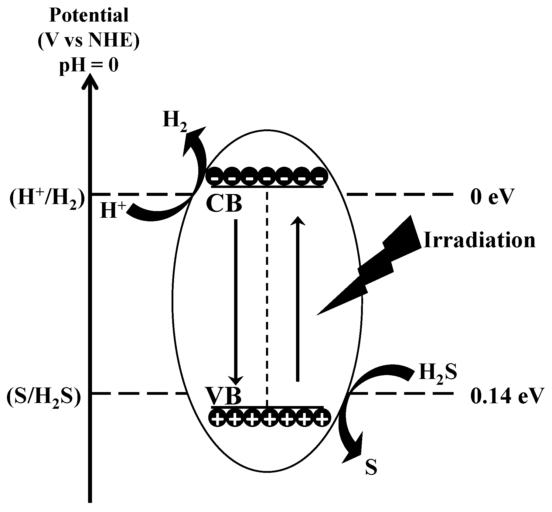
Photocatalysis is the phenomenon that occurs when a light source interacts with the surface of semiconductor materials. Unlike metals, which exhibit a continuum of electronic states, semiconductors have a distinct energy region known as the band gap. This region extends from the top of the filled valence band (VB) to the bottom of the vacant conduction band (CB). When a photon with energy equal to or greater than the band gap is absorbed by the semiconductor, an electron is excited from the VB to the CB, creating a positive hole in the valence band. For the splitting of H2S, the CB edge of a photocatalyst needs to have a more negative potential than that of H2 generation (H+/H2, 0 V vs. NHE—Normal Hydrogen Electrode), and the VB edge must be more positive than the potential required for S generation (S/H2S, 0.14 V vs. NHE). The entire process can be schematized as (see Figure 14 for clarity):
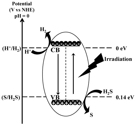
Figure 14.
Mechanism of decomposition of H2S by photocatalysis.
In general, most semiconductors exhibit sufficiently negative CB potentials and positive VB potentials for realizing the H2S splitting to H2. Photocatalysts such as ZnO, TiO2, ZnS, MnS, CdS, In2S3, ZnIn2S4 are promising candidates [68]. The photocatalytic decomposition of H2S can take place either in the gas phase or in the liquid phase.
- Photocatalytic decomposition in the liquid phase is more commonly employed than in the gas phase for several reasons [69]:
- The absorption of H2S by liquids, such as basic aqueous solution or ethanolamine, is a widely accepted strategy to collect H2S gas;
- It enables the achievement of higher H2S concentrations (often in the ppm level in the gas phase).
Three types of solutions have been considered for dissolving H2S and subsequent photocatalytic decomposition [70]: solutions of alkaline sulfides (H2S dissolved in Na2S/Na2SO3 solutions), solutions of alkaline hydroxides (H2S dissolved in NaOH or KOH solutions) and solutions of alkanolamines, as monoethanolamine (MEA), diethanolamine (DEA), and triethanolamine (TEA).
As for now, various semiconductors and supports have been identified as effective photocatalysts to produce hydrogen. Widely studied semiconductors for photocatalysis are [71]:
- Metal oxides (binary and ternary): d0 metal oxides (TiO2, ZrO2, SrTiO3, Ta2O5, Bi2W2O9, and Nb2O5), d10 metal oxides (ZnO, In2O3), f0 metal oxides (CeO2);
- Metal sulfides: ZnS, MnS, CdS, CuInS2, AgIn2S2, and their solid solutions. CdS, with a 2.4 eV band gap is particularly noteworthy due to its responsiveness to visible light.
Sacrificial agents play a crucial role in promoting hydrogen production by interaction with the photo-generated holes, preventing the recombination of charges between photo-generated electrons and holes. Commonly utilized sacrificial agents for the photocatalytic decomposition of H2S include sulfide (e.g., Na2S), sulfite (e.g., Na2SO3), or thiosulfate.
A summary of recent advances on the photocatalytic splitting of H2S in aqueous solutions of Na2S/Na2SO3 is reported by Oladipo et al. [70]. The photolytic hydrogen production from aqueous phase H2S dissolved in an alkaline solution possesses various challenges, including the need for UV (UltraViolet) light irradiation and the shielding of reactants by in situ generated disulfide ions. Other studies have explored the use of ethanolamine as an alternative aqueous solution to alkaline hydroxides, offering potential solutions to these challenges. Naman et al. [72] analyzed hydrogen production from H2S absorbed in 3 different aqueous ethanolamine solutions: 20% MEA, 20% DEA, and 20% TEA. In the pursuit of optimizing reaction conditions, an investigation was conducted on this photocatalytic process using 3 distinct catalysts (TiO2, CdSe, and CdS), covering a temperature range from 30 to 80 °C. Different effects of the temperature for the three solutions was discovered. The highest production was achieved in aqueous MEA solution using the TiO2 catalyst. More recently, Ma et al. [73] extensively studied hydrogen production from H2S dissolved in different pure ethanolamines using noble metal-CdS composites. The Pt/CdS photocatalyst showed high activity and the highest activity was observed for DEA.
Nearly all the catalysts examined for this process have demonstrated quantum yields below 50%, with the exception of one catalyst reported by Yan et al. [74]. They utilized a visible light-driven Pt-PdS/CdS catalyst, achieving a quantum yield of 93%.
Solid particle dynamics calculations and computational fluid dynamics were employed by Jing et al. [75] to simulate fluidized bed reactors for the photocatalytic H2S splitting. The authors asserted that a fluidized-bed annular photocatalytic reactor, irradiated by a UV lamp positioned along the axis, could represent a viable approach for developing large-scale photocatalytic reactors. Following numerical investigations, a fluidized bed photocatalytic reactor was constructed, employing pure H2S as the gas for catalyst suspension. They observed that the activity of the reaction in the fluidized bed reactor surpassed that in a batch reactor in a Na2S/Na2SO3 solution [76].
- 2.
- Photocatalytic decomposition in gas phase. Very few studies of the gas-phase photocatalytic process have been reported, which emphasized the problem of catalyst deactivation. Canela et al. [77] performed the photocatalytic decomposition of H2S in the gas phase, employing TiO2 as the catalyst, and noted catalyst deactivation at H2S concentrations exceeding 600 ppmv. Kataoka and coauthors [78] conducted analogous experiments and determined that H2S underwent oxidation to form SO42− without generating notable gaseous intermediates like SO, SO2, and SO2−. Portela et al. [79] investigated H2S decomposition with initial concentration of 15 ppm in the gas phase using heterogeneous photocatalysts. They also noted the accumulation of SO42− on the photocatalyst surface, resulting in deactivation. Gujun et al. [80] investigated photocatalytic decomposition of H2S in the gas phase to produce H2 in an anaerobic environment, employing five semiconductor photocatalysts (ZnO, TiO2, ZnS, CdS and ZnIn2S4). ZnS exhibited the maximum rate of hydrogen production, and the introduction of Cu2+ during the ZnS catalyst preparation promoted its activity. The addition of Ir was found to be effective as well in enhancing hydrogen production. More recently, Lou et al. [81] proposed the SiO2-supported Au as photocatalyst for the decomposition of H2S using visible light. Reaction rates up to 20 times higher than thermocatalysis at nominally the same surface temperatures were claimed by the author, because of the photogenerated HCs, which accelerates the second H–S bond scission. In the same year, anatase/TiO2(B) nanotubes were applied to favor H2S decomposition or oxidation at concentrations below several ppb, at a kinetic rate of 75 μmol h−1 g−1.
The latest tendencies for H2S photocatalysis, also considering its modeling by quantum mechanical and molecular simulation approaches has been recently published by Li and coworkers [82].
The gas-phase approach encounters various challenges, including:
- Low productivity (80 μmol∙g−1∙h−1);
- Catalyst deactivation due to sulfur poisoning;
- High relative humidity negatively affecting the photocatalytic splitting of H2S, as water competes for adsorption on active surface sites required for H2S decomposition;
- Research indicates that ZnS is an effective photocatalyst for H2S splitting in the gas phase, yielding a significant amount of H2 compared with other metal oxides or sulfides like ZnO, TiO2, and CdS. However, ZnS faces issues of photo-corrosion, prompting efforts to develop nanostructures based on ZnS heterojunctions.
The advantages and disadvantages of the photocatalytic decomposition of H2S are summarized in Table 13. The TRL of this technology, compatibly with the guidelines provided by NASA [48], is 3. Unlike the other H2S decomposition technologies, the applicability of the methodology on a scale other than the laboratory one is not known. For this reason, further research is essential before considering the commercialization of the process.

Table 13.
Advantages and disadvantages of the H2S photocatalytic decomposition process.
4.2. Thermochemical Decomposition through Cycles
The thermochemical decomposition of H2S through cycles involves the reaction with compounds that cause H2S decomposition. These compounds are then regenerated to be reused in the process. They are distinguished in iodine cycles, cycles with sulfurization of metals, inorganic sulfides or oxides and CO/COS cycles.
- Iodine cycles, divided in turn into two-step cycles with iodine and three-step cycles with iodine and sulfuric acid.
The production of hydrogen in the two-step process takes place via reactions (20) and (21) [83]:
The precise mechanism of reaction (20) remains unclear. Gillis et al. [83] observed that the solvation of HI in I2 must take place in the aqueous phase. Reaction (20) is characterized by a negative Gibbs free energy of reaction (−71.6 kJ∙mol−1), indicating that the H2S consumption in the water phase is a spontaneous reaction.
The separation of water from the mixture of products thus formed (usually called the HIx mixture) is particularly problematic, as well as expensive, caused by the presence of an azeotrope which hinders the application of simple distillation as unit operation [83]. While isopropyl alcohol can be employed as a solvent to reduce the costs associated with vaporizing the aqueous phase, fundamental problems such as solvent vaporization and condensation make the process economically and environmentally uncompetitive. Additionally, concerns arise regarding the side reactions of iodine with water:
Nevertheless, process modelling indicated that the I2 thermochemical cycle may be cost-competitive and environmentally superior compared with existing industrial practices [83].
The H2S splitting cycle, a three-step process, was initially introduced by Goldstein et al. [84]. It relies on the multistep sulfur-iodine water splitting thermochemical process [19]:
In the presence of oxygen, the sulfur is oxidized to SO2: the quantity of SO2 circulating in the process therefore doubles and from one mole of H2S two moles of H2 are obtained [19]. The Bunsen reaction, a moderately exothermic reaction, plays a crucial role in both H2S splitting and sulfur-iodine water splitting cycles, because it connects H2S oxidation and hydroiodic decomposition in the H2S splitting cycle and it also serves to link the sulfur and the iodine loops of the sulfur-iodine water splitting cycle. The company General Atomics (GA) conducted an extensive investigation into this reaction to optimize conditions for achieving the maximum separation of the two produced acids. GA concluded that employing any thermal methods without reversing the equilibria would not lead to the separation of both acids unless excess quantities of H2O and I2 are utilized (creating a two-phase system) [85]. The relative proportions of H2O and I2 drive the formation of two immiscible phases: a lighter H2SO4/H2O and a heavier HI/I2/H2O phase (HIx mixture), which must undergo concentration before decomposition. The downstream sections face significant challenges as the diluted streams need further concentration and purification [85].
Wang et al. [86] introduced a low-temperature process in which toluene was employed to dissolve iodine, enabling the continuous execution of the Bunsen reaction at room temperature while bypassing the technical challenges associated with GA’s Bunsen reaction. As outlined by Wang et al. [86], H2S was initially oxidized with concentrated sulfuric acid (94–98 wt%). Subsequently, the produced SO2 underwent a reaction with stoichiometric quantities of I2 dissolved in H2O and toluene at ambient temperature, resulting in a multiphase system (gas-liquid-liquid) [87].
Li et al. [87] analyzed how the apparent absorption/reaction rate of sulfur dioxide in a batch reactor is impacted by operational parameters, including liquid volume, H2O/toluene volume ratio and agitation speed.
The Thiozen company from Massachusetts Institute of Technology (MIT) is focused on commercializing the iodine cycle technology to generate low emission hydrogen from sour gases [7].
- 2.
- Cycles with sulfurization of metals, inorganic sulfides or oxides. A metal M or a sulfide MxSy having affinity with sulfur are used as a substrate to capture sulfur from hydrogen sulfide according to the Kiuchi type-1 reactions [88]:
The metal sulfides thus obtained are regenerated by thermal decomposition through:
Ag proved to be suitable for reactions (26) and (27) while Fe, Co, Ni, V and Mo sulfides provided satisfactory results with reactions (28) and (29) [88,89].
During the regeneration process in the presence of oxygen (Kiuchi type-2 scheme), sulfides may generate oxides and sulfates, posing a risk to the reversibility of the overall process, except when M = Cu and Ag. In such cases, the metal can undergo regeneration through a mutual reaction involving sulfides and oxides or sulfates, following established metallurgical processes:
The reaction (31) conversion could exceed 90% when M = Ag and T = 550 °C.
Despite the presence of numerous patents, none of these approaches has resulted in large-scale industrial applications [90].
Recently, Zagoruiko and Mikenin [91] studied sulfides of transient metals (Fe, Co, and Ni) both in bulk and supported forms. They observed highest efficiency with bulk sulfides NiS, CoS, and FeS, with the conversion of H2S and the yield of H2 higher than the equilibrium values for direct H2S decomposition reaction. For the optimal temperature range 350–400 °C, the average H2 yield of 26–34% per cycle was observed.
- 3.
- CO/COS cycles. Zaman and Chakma [89] outlined a process that relies on the utilization of CO as intermediate reactant, which is consumed and subsequently regenerated through the following steps:
Unfortunately, a portion of carbonyl sulfide is lost due to a disproportionation reaction, resulting in the formation of carbon disulfide:
Reaction (35) is considered the main obstacle to the real application of this scheme.
Gibson and Wachs [92] obtained a satisfactory regeneration of CO by catalytic oxidation:
The reactions (36) and (37) were carried out on metal oxides or silica supported catalysts. The most favorable outcomes were achieved by applying a 5% V2O5 surface coating on Nb2O5 support for reaction (36) and employing the same coating on a SiO2 support for reaction (37). However, a significant drawback of H2S decomposition according to Wachs’ scheme is the production of SO2 instead of elemental sulfur. Consequently, post-processing is necessary, similar to the regeneration of metal sulfides described earlier, involving the use of oxygen.
The advantages and disadvantages of the H2S decomposition process via iodine, metal or sulfide cycles are reported in Table 14. The TRL of this technology, compatibly, with the guidelines provided by NASA, is 4 [48]. The complexity of the nature of the reacting system and of the separations to be carried out downstream the reactor currently pose challenges to scaling up the process beyond laboratory levels.

Table 14.
Advantages and disadvantages of the H2S thermochemical decomposition by cycles of iodine, metals, or sulfides.
4.3. Thermocatalytic Decomposition
The conversion of reaction (38) is limited to relatively small values even at high temperatures due to its thermodynamic equilibrium [93]. For example, at a temperature of 950 °C and pressure of 1.01 bar the conversion is about 15% [94]. The thermocatalytic decomposition of H2S is based on the use of a catalyst with the aim of decreasing the temperature of reaction (38).
The commonly employed catalysts are metal sulfides [95,96]. Chivers et al. [93] reported that MoS2, Cr2S3, and WS2 catalysts demonstrated effectiveness at temperatures above 600 °C, with Cr2S3 and WS2 exhibiting higher H2 yields below 600 °C compared with MoS2. Startsev [97] studied Ni3S2 and CoS2 for H2S conversion at ambient temperature. Al2O3 was used as a catalyst for H2S decomposition in the work by Bandermann and Harder [94]. Yumura and Furimsky [98,99] investigated the dissociative adsorption of H2S at elevated temperatures on various oxides such as CaO, ZnO, Fe2O3, and Mn3O4, and reported that significant production of SO2. Alexeeva [100] examined catalysts obtained through vacuum methods of catalytic coating deposition. Carbon fibrous materials and alumina were employed as supports, with Mo, W, and various other metals or metal oxides deposited using either electron beam evaporation or magnetron sputtering. The resulting catalysts exhibited effective thermostability. Vaiano et al. [101] prepared, characterized and tested MoS2 phases supported on Al2O3 with varying content ranging from 5 to 20 wt%. Results from the chemical-physical characterization revealed a well-dispersed MoS2 on the Al2O3 support. MoS2 loading, in comparison to Al2O3, particularly influenced the H2 yield and reduced the SO2 production, while maintaining a relatively consistent H2S conversion (~50%). The catalyst with a nominal MoS2 loading of 10 wt% exhibited the highest H2 yield. To further understand the system, a predictive mathematical model was developed by identifying the main reactions occurring in the system and verifying it in the temperature range between 800 and 1000 °C.
The use of membranes to remove the products from the reaction zone is investigated with the aim of overcoming the thermodynamic and kinetic limitations on H2S conversion. Edlund and Pledger [102] performed experimental studies on a composite-metal membrane permeable to H2, featuring a platinum coating layer on the feed side. At 700 °C and under partial pressures of up to 8 bar, the platinum layer demonstrated resistance to irreversible chemical attack by hydrogen sulfide. Employed in a laboratory-scale membrane reactor, this membrane facilitated the splitting of H2S with a remarkable efficiency, achieving over 99.4% conversion. The resulting by-products are sulfur and H2, with no formation of sulfur oxides. Akamatsu et al. [103] designed a membrane reactor using an amorphous silica membrane and a commercially available catalyst for decomposing H2S into hydrogen. The membrane exhibited outstanding hydrogen permeance, approximately 10−7 mol m−2∙s−1∙Pa−1, at 600 °C, along with a notable H2/N2 permselectivity of 104. The system demonstrated a conversion surpassing the equilibrium conversion level. Kameyama et al. [104] explored the viability of employing microporous ceramic membranes in the production of H2 from H2S. A microporous Vycor-type glass tubing membrane, with an average pore diameter of 45 Å, and a novel microporous alumina tubing membrane, with a diameter of 1020 Å, were identified as suitable for use up to 800 °C and at higher temperatures, respectively. Notably, the microporous alumina tubing membrane exhibited a 30-fold higher permeability than the microporous Vycor glass tubing membrane. When applied to the direct decomposition of H2S, these membranes increased the H2 yield by approximately 2 times the equilibrium yield calculated for the process without H2 removal.
The advantages and disadvantages of the thermocatalytic decomposition technology are shown in Table 15. The TRL of this process, compatibly with the guidelines provided by NASA [48], is 4. It is necessary to deepen the research on a laboratory scale in order to think about an industrialization of this technology.

Table 15.
Advantages and disadvantages of the H2S thermocatalytic decomposition process.
4.4. Decomposition via Electrolysis
Electrolysis uses electricity to promote the decomposition of the reacting species. Specifically, for H2S, three methods are typically distinguished: direct, indirect, and other methods.
- Direct methods, typically based on the use of an electrolytic cell in an alkaline medium. The direct electrochemical splitting of H2S is represented by the two half-reactions:
Direct methods present lower power consumption than indirect ones and, in principle, can apply the same technology used for water splitting. The main problem of this methodology is the anode passivation from sulfur [105]. The solubility of sulfur in alkaline media lead to the formation of polysulfides, which tend to precipitate from the solution and, therefore, interfere with the production of hydrogen. To facilitate the removal of sulfur, the introduction of vapors or organic solvents into the system has been proposed rather than the use of filters or membranes [106].
Ma et al. [107] investigated a novel organic electrolyte system that utilizes tetraethylene glycol dimethyl ether as the solvent, the ionic liquid [C3OHmim]BF4 as the supporting electrolyte and MEA as the absorbent for H2S. Notably, no sulfur was observed to attach to the anode during electrolysis, addressing issues associated with anodic passivation. The addition of MEA demonstrated a substantial enhancement in the sulfur solubility of the electrolyte, improving the efficiency of H2S electrolysis.
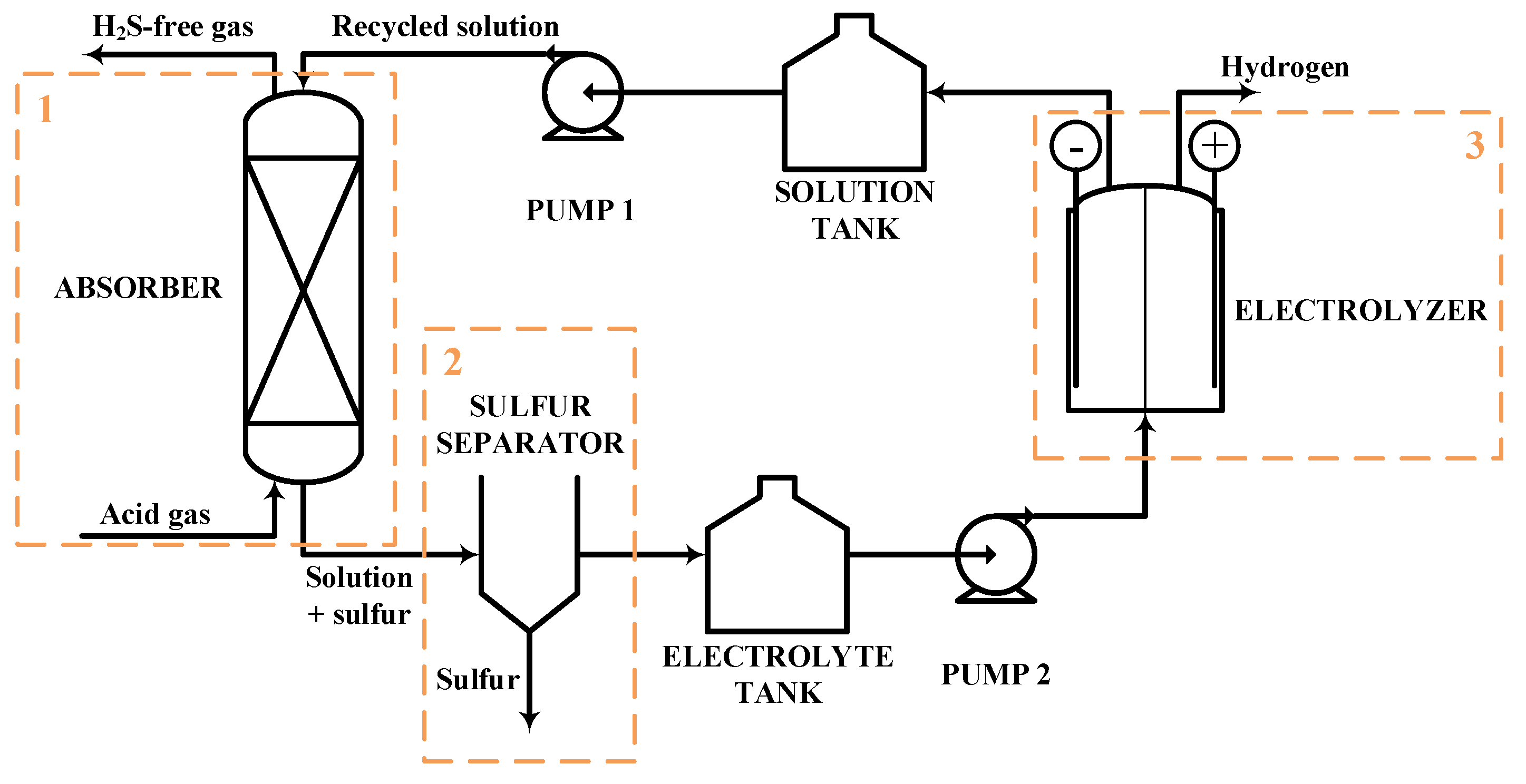
- 2.
- Indirect methods, involving the use of a co-oxidizing agent (typically, metals, metal oxides, or iodides) to promote the conversion of sulfides to elemental sulfur. The process, depicted in Figure 15, is split into three separate steps: chemical absorption (1), sulfur separation (2) and electrochemical conversion (3). Inside the absorber, elemental sulfur is formed and, after its separation, the resulting solution is passed through the electrolysis cell where hydrogen is released and the starting medium is regenerated. Acidic aqueous solutions of Fe3+/Fe2+, (VO2)+/(VO)2+ or FeCl2/FeCl3, as the electrochemical intermediate, are currently the most promising systems [108].
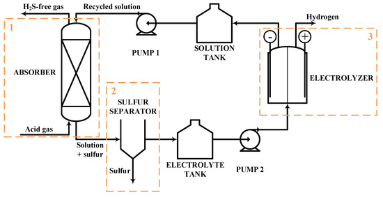 Figure 15. Indirect electrolysis process scheme where chemical absorption (1), sulfur separation (2) and electrochemical conversion (3) sections are highlighted.
Huang et al. [20] studied the H2S absorption and conversion to H2 and S in an acidic aqueous vanadium dioxide (VO2) solution coupled with indirect electrolysis. Parametric analyses were carried out to assess the impact of operating parameters on both absorption and electrochemical reactions. The results revealed that H2S absorption increases with temperature, surpassing 90% absorption 50 °C, with the absorption reaction being mass-transfer-limiting. In the electrolysis reaction, a current efficiency of 97% was achieved at 45 °C after an extended electrolysis time. The study also addressed the ease of recovering sulfur particles.
Adewale et al. [109] conducted a process simulation study on the Fe-Cl hybrid process of Idemitsu Kosan Co., for the production of H2 and S from H2S gas streams. The researchers modeled and validated the process using data from a pilot-scale plant before scaling it up. The study investigated the impacts of absorber solution flowrate and concentration on the operability of the process. It was observed that operating with high ferric ions concentration yielded more favorable results compared with operations with high solution flowrates. The presence of ferrous ions in the solution played a crucial role in the downstream electrolysis process.
- 3.
- Other methods, which are based on the use of high temperatures to favor the formation of sulfur in the liquid and gas phase. However, these methodologies are at a preliminary stage [110]. Several research groups have explored the integration of renewable energy into H2S electrolysis. One example involves modeling the production of hydrogen from H2S within geothermal power plants using electrolysis methods [111]. This approach involves abatement of mercury emission, selective catalytic oxidation of H2S to SO2, and SO2 scrubbing using geothermal water. The H2S, obtained from gaseous emissions, is separated to the pure H2 and gaseous S2 using a proton exchange membrane (PEM) electrolyzer operating at 150 °C. Thermodynamic calculations and parametric studies were conducted by varying multiple process parameters. The energy and exergy efficiencies of the process were determined as 27.8% and 57.1%, respectively, at an inlet temperature of H2S of 150 °C. In another study [112], various models were developed for the use of biogas-based electricity and sewage sludge obtained from a municipal wastewater treatment plant for H2 production. These models included alkaline, PEM, high temperature water electrolysis, alkaline hydrogen sulfide electrolysis, and dark fermentation biohydrogen production processes. Energy and economic analyses were conducted on these models. Regarding the H2 production rate, the high temperature electrolysis process demonstrated superiority over the other models, with PEM electrolysis following closely behind. However, concerning H2 production cost, H2S electrolysis outperformed the other models.
The advantages and disadvantages of the electrolysis decomposition process are shown in Table 16. The TRL of this technology, compatibly with the guidelines provided by NASA [48], is 4. It is necessary to propose solutions that, on a laboratory scale, can solve the difficulties associated with process management, in order to be able to think about its industrialization.

Table 16.
Advantages and disadvantages of the H2S decomposition via electrolysis.
5. Conclusions
Considering the environmental challenges that we are facing today about the toxic emissions abatement, together with the increasing importance of circular economy concepts, the study of novel waste valorization processes is of great interest in the chemical engineering panorama.
Considering H2S valorization to H2, the methane reformation process and the non-thermal plasma H2S conversion are analyzed. For the non-thermal plasma H2S conversion to H2, a preliminary feasibility study is presented, considering that its scalability to the industrial level has not been yet demonstrated. This is not the case of the hydrogen production through H2S methane reformation, which can be considered a traditional H2S conversion pathway. The H2SMR presents several advantages, such as the high H2 yield (for each mole of methane reacted, 4 moles of hydrogen produced) and the absence of direct CO2 emissions, in contrast to conventional steam methane reforming. To comprehend the reacting system and consider process scalability, an in-depth thermodynamic analysis is conducted. Thermodynamic equilibrium calculations reveal that carbon deposition during the reaction phase can be significantly influenced by temperature and pressure, with a higher likelihood at high pressure and low temperature. Additionally, the composition of the feed is responsible of either promoting or preventing coke formation. Notably, the presence of H2O and CO2 proves beneficial in preventing carbon deposition, while the existence of C2+ traces in the feed stream is undesired in this context. However, if the desired product is H2, careful management of impurities in the reactants’ mixture is essential due to the potential production of CO, COS, and other sulfur-based compounds. Techno-economic evaluations of the process are based on a simplified process scheme and are carried out with varying CH4 /H2S inlet molar ratio. Fixed and operating costs are evaluated for each investigated case and hydrogen cost is retrieved to identify the optimal process operating conditions in terms of the inlet reactants molar ratio. The perspective of the process depends on the reaction section operating conditions, temperature, and pressure, which must be sufficiently low for the technology application to the industrial scale. The other technologies analyzed, photocatalytic decomposition, thermochemical decomposition through cycles, thermocatalytic decomposition and decomposition via electrolysis, are too immature to be industrialized: further research is needed to deepen their chemical-physical phenomena on a laboratory scale. Most of the thermocatalytic technologies suffer from unfavorable thermodynamic equilibria and poor yields. In this case, a modification of the traditional reaction equipment with the addition of membranes for H2 removal can be beneficial to overcome unfavorable equilibria. However, fundamental research is needed to identify more efficient catalysts operating at milder conditions.
Regarding photocatalysis, significant advances have been made in the development of photocatalyst efficiencies. Nevertheless, the lack of effective photo reactors and separation processes hinders the process application at large scale.
Direct electrochemical methods are not viable considering the-state-of-the-art, due to the deterioration of metal electrodes because of sulfur passivation, while indirect electrolysis involving a Fe-Cl cycle, may be a promising route for large scale implementing. Strategies for the integration of renewable energy could be helpful for process application to the industrial level.
Author Contributions
Conceptualization, E.S. and L.A.P.; methodology, E.S., F.R. and L.A.P.; investigation, E.S. and F.R.; project administration, A.R.d.A. and L.A.P.; writing—original draft preparation, E.S. and F.R.; writing—review and editing, A.R.d.A. and L.A.P.; visualization, E.S. and F.R.; supervision, A.R.d.A. and L.A.P. All authors have read and agreed to the published version of the manuscript.
Funding
This research received no external funding.
Data Availability Statement
Data sharing not applicable.
Conflicts of Interest
Author Alberto R. de Angelis was employed by the company Eni. The remaining authors declare that the research was conducted in the absence of any commercial or financial relationships that could be construed as a potential conflict of interest.
References
- IEA Publications & International Energy Agency. Gas Market Report Q3-2021. Available online: https://iea.blob.core.windows.net/assets/4fee1942-b380-43f8-bd86-671a742db18e/GasMarketReportQ32021_includingGas2021Analysisandforecastto2024.pdf (accessed on 22 June 2023).
- De Guido, G.; Messinetti, F.; Spatolisano, E. Cryogenic Nitrogen Rejection Schemes: Analysis of Their Tolerance to CO2. Ind. Eng. Chem. Res. 2019, 58, 17475–17488. [Google Scholar] [CrossRef]
- Pellegrini, L.A.; Gilardi, M.; Giudici, F.; Spatolisano, E. New solvents for CO2 and H2S removal from gaseous streams. Energies 2021, 14, 6687. [Google Scholar] [CrossRef]
- De Guido, G.; Pellegrini, L.A. Calculation of solid-vapor equilibria for cryogenic carbon capture. Comput. Chem. Eng. 2022, 156, 107569. [Google Scholar] [CrossRef]
- De Guido, G.; Langè, S.; Moioli, S.; Pellegrini, L.A. Thermodynamic method for the prediction of solid CO2 formation from multicomponent mixtures. Process Saf. Environ. Prot. 2014, 92, 70–79. [Google Scholar] [CrossRef]
- Spatolisano, E.; de Angelis, A.R.; Pellegrini, L.A. Middle Scale Hydrogen Sulphide Conversion and Valorisation Technologies: A Review. ChemBioEng Reviews 2022, 9, 370–392. [Google Scholar] [CrossRef]
- De Guido, G.; Monticelli, C.; Spatolisano, E.; Pellegrini, L.A. Separation of the Mixture 2-Propanol+ Water by Heterogeneous Azeotropic Distillation with Isooctane as an Entrainer. Energies 2021, 14, 5471. [Google Scholar] [CrossRef]
- Spatolisano, E.; Pellegrini, L.A.; Gelosa, S.; Broglia, F.; Bonoldi, L.; de Angelis, A.R.; Moscotti, D.G.; Nali, M. Polythionic acids in the Wackenroder reaction. ACS Omega 2021, 6, 26140–26149. [Google Scholar] [CrossRef] [PubMed]
- De Guido, G.; Pellegrini, L.A.; Besagni, G.; Inzoli, F. Acid Gas Removal from Natural Gas by Water Washing. Chem. Eng. Trans. 2017, 57, 1129–1134. [Google Scholar] [CrossRef]
- Spatolisano, E.; Pellegrini, L.A.; Bonoldi, L.; de Angelis, A.R.; Moscotti, D.G.; Nali, M. Kinetic modelling of polythionic acids in Wackenroder reaction. Chem. Eng. Sci. 2022, 250, 117403. [Google Scholar] [CrossRef]
- T-Raissi, A. Technoeconomic Analysis of Area II Hydrogen Production-Part 1; Florida Solar Energy Center: Cocoa, FL, USA, 2001. [Google Scholar]
- Restelli, F.; Spatolisano, E.; Pellegrini, L.A.; Cattaneo, S.; de Angelis, A.R.; Lainati, A.; Roccaro, E. Liquefied hydrogen value chain: A detailed techno-economic evaluation for its application in the industrial and mobility sectors. Int. J. Hydrogen Energy 2024, 52, 454–466. [Google Scholar] [CrossRef]
- Restelli, F.; Spatolisano, E.; Pellegrini, L.A.; de Angelis, A.R.; Cattaneo, S.; Roccaro, E. Detailed techno-economic assessment of ammonia as green H2 carrier. Int. J. Hydrogen Energy 2023, 52, 532–547. [Google Scholar] [CrossRef]
- Spatolisano, E.; Restelli, F.; Matichecchia, A.; Pellegrini, L.A.; de Angelis, A.R.; Cattaneo, S.; Roccaro, E. Assessing opportunities and weaknesses of green hydrogen transport via LOHC through a detailed techno-economic analysis. Int. J. Hydrogen Energy 2024, 52, 703–717. [Google Scholar] [CrossRef]
- Hwang, J.; Maharjan, K.; Cho, H. A review of hydrogen utilization in power generation and transportation sectors: Achievements and future challenges. Int. J. Hydrogen Energy 2023, 48, 28629–28648. [Google Scholar] [CrossRef]
- Spatolisano, E.; De Guido, G.; Pellegrini, L.A.; Calemma, V.; de Angelis, A.R.; Nali, M. Hydrogen sulphide to hydrogen via H2S methane reformation: Thermodynamics and process scheme assessment. Int. J. Hydrogen Energy 2022, 47, 15612–15623. [Google Scholar] [CrossRef]
- Gutsol, K.; Nunnally, T.; Rabinovich, A.; Fridman, A.; Starikovskiy, A.; Gutsol, A.; Kemoun, A. Plasma assisted dissociation of hydrogen sulfide. Int. J. Hydrogen Energy 2012, 37, 1335–1347. [Google Scholar] [CrossRef]
- Ruban, P.; Sellappa, K. Concurrent Hydrogen Production and Hydrogen Sulfide Decomposition by Solar Photocatalysis. CLEAN Soil Air Water 2016, 44, 1023–1035. [Google Scholar] [CrossRef]
- Wang, H. Hydrogen production from a chemical cycle of H2S splitting. Int. J. Hydrogen Energy 2007, 32, 3907–3914. [Google Scholar] [CrossRef]
- Huang, H.; Yu, Y.; Chung, K.H. Recovery of Hydrogen and Sulfur by Indirect Electrolysis of Hydrogen Sulfide. Energy Fuels 2009, 23, 4420–4425. [Google Scholar] [CrossRef]
- Restelli, F.; Gambardella, M.; Pellegrini, L.A. Green vs. fossil-based energy vectors: A comparative techno-economic analysis of green ammonia and LNG value chains. J. Environ. Chem. Eng. 2023, 12, 111723. [Google Scholar] [CrossRef]
- Raynal, L.; Briot, P.; Dreillard, M.; Broutin, P.; Mangiaracina, A.; Drioli, B.S.; Politi, M.; La Marca, C.; Mertens, J.; Thielens, M.-L. Evaluation of the DMX process for industrial pilot demonstration–methodology and results. Energy Procedia 2014, 63, 6298–6309. [Google Scholar] [CrossRef]
- Lay, M.D.S.; Sauerhoff, M.W.; Saunders, D.R. Carbon Disulphide. In Ullmann’s Encyclopedia of Industrial Chemistry; Kgaa, W., Ed.; Wiley-VCH Verlag GmbH & Co.: Weinheim, Germany, 2005. [Google Scholar]
- Zhuang, Q.; Clements, B.; Dai, J.; Carrigan, L. Ten years of research on phase separation absorbents for carbon capture: Achievements and next steps. Int. J. Greenhouse Gas Control 2016, 52, 449–460. [Google Scholar] [CrossRef]
- Megalofonos, S.K.; Papayannakos, N.G. Hydrogen production from natural gas and hydrogen sulphide. Int. J. Hydrogen Energy 1991, 16, 319–327. [Google Scholar] [CrossRef]
- Huang, C.; T-Raissi, A. Liquid hydrogen production via hydrogen sulfide methane reformation. J. Power Sources 2008, 175, 464–472. [Google Scholar] [CrossRef]
- Megalofonos, S.K.; Papayannakos, N.G. Kinetics of the catalytic reaction of methane and hydrogen sulphide over a Pt-Al2O3 catalyst. Appl. Catal. A Gen. 1996, 138, 39–55. [Google Scholar] [CrossRef]
- Megalofonos, S.K.; Papayannakos, N.G. Kinetics of catalytic reaction of methane and hydrogen sulphide over MoS2. Appl. Catal. A Gen. 1997, 165, 249–258. [Google Scholar] [CrossRef]
- Karan, K.; Behie, L.A. CS2 Formation in the Claus Reaction Furnace: A Kinetic Study of Methane-Sulfur and Methane-Hydrogen Sulfide Reactions. Ind. Eng. Chem. Res. 2004, 43, 3304–3313. [Google Scholar] [CrossRef]
- Galindo-Hernàndez, F.; Domínguez, J.M.; Portales, B. Structural and textural properties of Fe2O3/g-Al2O3 catalysts and their importance in the catalytic reforming of CH4 with H2S for hydrogen production. J. Power Sources 2015, 287, 13–24. [Google Scholar] [CrossRef]
- Martìnez-Salazar, A.L.; Melo-Banda, J.A.; Domìnguez- Esquivel, J.M.; Martìnez-Sifuentes, V.H.; Salazar-Cerda, Y.; Coronel-Garcìa, M.A.; Meraz-Melo, M.A. Hydrogen production by methane and hydrogen sulphide reaction: Kinetics and modeling study over Mo/La2O3-ZrO2 catalyst. Int. J. Hydrogen Energy 2015, 40, 17354–17360. [Google Scholar] [CrossRef]
- Martìnez-Salazar, A.L.; Melo-Banda, J.A.; Reyes de la Torre, A.I.; Salazar-Cerda, Y.; Coronel-Garcìa, M.A.; Portales, B.; Martìnez-Sifuentes, V.H.; Domìnguez- Esquivel, J.M.; Silva Rodrigo, R. Hydrogen production by methane reforming with H2S using Mo,Cr/ZrO2-SBA15 and Mo,Cr/ZrO2-La2O3 catalysts. Int. J. Hydrogen Energy 2015, 40, 17272–17283. [Google Scholar] [CrossRef]
- El-Melih, A.M.; Al Shoaibi, A.; Gupta, A.K. Hydrogen sulfide reformation in the presence of methane. Appl. Energy 2016, 178, 609–615. [Google Scholar] [CrossRef]
- El-Melih, A.M.; Iovine, I.; Al Shoaibi, A.; Gupta, A.K. Production of hydrogen from hydrogen sulfide in presence of methane. Int. J. Hydrogen Energy 2017, 42, 4764–4773. [Google Scholar] [CrossRef]
- Li, Y.; Yu, X.; Li, H.; Guo, Q.; Dai, Z.; Yu, G.; Wang, F. Detailed kinetic modeling of homogeneous H2S-CH4 oxidation under ultra-rich condition for H2 production. Appl. Energy 2017, 208, 905–919. [Google Scholar] [CrossRef]
- AspenTech. Aspen Plus®; AspenTech: Burlington, MA, USA, 2016. [Google Scholar]
- Tollini, F.; Sponchioni, M.; Calemma, V.; Moscatelli, D. Methane Reforming with H2S and Sulfur for Hydrogen Production: Thermodynamic Assessment. Energy Fuels 2023, 37, 11197–11208. [Google Scholar] [CrossRef]
- Ryaboshapka, D.; Piccolo, L.; Aouine, M.; Bargiela, P.; Briois, V.; Afanasiev, P. Ultradispersed (Co) Mo catalysts with high hydrodesulfurization activity. Appl. Catal. B Environ. 2022, 302, 120831. [Google Scholar] [CrossRef]
- Zheng, J.; Impeng, S.; Liu, J.; Deng, J.; Zhang, D. Mo promoting Ni-based catalysts confined by halloysite nanotubes for dry reforming of methane: Insight of coking and H2S poisoning resistance. Appl. Catal. B Environ. 2024, 342, 123369. [Google Scholar] [CrossRef]
- Erekson, E.J. Gasoline from Natural Gas by Sulfur Processing. In Final Technical Report, June 1993–July 1996; Institute of Gas Technology: Des Plaines, IL, USA, 1996. [Google Scholar]
- Wang, Y.; Chen, X.; Shi, H.; Lercher, J.A. Catalytic reforming of methane with H2S via dynamically stabilized sulfur on transition metal oxides and sulfides. Nat. Catal. 2023, 6, 204–214. [Google Scholar] [CrossRef]
- Martìnez-Salazar, A.L.; Melo-Banda, J.A.; Coronel-Garcìa, M.A.; García-Vite, P.M.; Martìnez-Salazar, I.; Domìnguez-Esquivel, J.M. Technoeconomic analysis of hydrogen production via hydrogen sulfide methane reformation. Int. J. Hydrogen Energy 2019, 44, 122296–122302. [Google Scholar] [CrossRef]
- Spatolisano, E.; De Guido, G.; Pellegrini, L.A.; Calemma, V.; de Angelis, A.R.; Nali, M. Process sensitivity analysis and techno-economic assessment of hydrogen sulphide to hydrogen via H2S methane reformation. J. Cleaner Prod. 2022, 330, 129889. [Google Scholar] [CrossRef]
- Steudel, R. Elementar Sulfur and Rich Compounds I; Springer: Berlin/Heidelberg, Germany, 2003. [Google Scholar]
- Kohl, A.L.; Nielsen, R. Gas Purification; Gulf Professional Publishing: Houston, TX, USA, 1997. [Google Scholar]
- Turton, R.; Bailie, R.C.; Whiting, W.B.; Shaeiwitz, J.A. Analysis, Synthesis and Design of Chemical Processes; Pearson Education: London, UK, 2008. [Google Scholar]
- Ali, S.M.; Alkhatib, I., II; AlHajaj, A.; Vega, L.F. How sustainable and profitable are large-scale hydrogen production plants from CH4 and H2S? J. Cleaner Prod. 2023, 428, 139475. [Google Scholar] [CrossRef]
- Pellegrini, L.A.; De Guido, G.; Langè, S.; Moioli, S.; Picutti, B.; Vergani, P.; Franzoni, G.; Brignoli, F. The Potential of a New Distillation Process for the Upgrading of Acid Gas. In Proceedings of the Abu Dhabi International Petroleum Exhibition & Conference (ADIPEC), Abu Dhabi, UAE, 7–10 November 2016. [Google Scholar]
- Gallon, H.J.; Whitehead, C. Dry Reforming of Methane Using Non-Thermal Plasma-Catalysis. Ph.D. Thesis, University of Manchester, Manchester, UK, 2011. [Google Scholar]
- Ansys. Chemkin-Pro; Ansys: Canonsburg, PA, USA, 2016. [Google Scholar]
- Balebanov, A.V.; Butylin, B.A.; Jivotov, V.K.; Krokvenko, V.I.; Matolich, R.M.; Macheret, S.S.; Novikov, G.I.; Potapkin, B.V.; Rusanov, V.D.; Fridman, A.; et al. Dissociacia serovodoroda v plasme. Dokl. Akad. Nauk. SSSR 1985, 283, 657–660. (In Russian) [Google Scholar]
- Krasheninnikov, E.G.; Rusanov, V.D.; Sanyuk, S.V.; Fridman, A.A. Dissociation of hydrogen sulfide in an RF discharge. Zhurnal Tek. Fiz. 1986, 56, 1104–1109. [Google Scholar]
- Gutsol, A. Plasma Dissociation of Hydrogen Sulfide. Master’s Thesis, Drexel University, Philadelphia, PA, USA, 2012. [Google Scholar]
- Kasharin, A.V.; Potapkin, B.V.; Rusanov, V.D.; Fridman, A.A. Energetics of plasma-chemical systems in selective transfer processes. J. Eng. Phys. 1989, 57, 1335–1343. [Google Scholar] [CrossRef]
- Balebanov, A.V.; Butylin, B.A.; Zhivotov, V.K.; Krokvenko, V.I.; Matolich, R.M.; Macheret, S.S.; Novikov, G.I.; Potapkin, B.V.; Rusanov, V.D.; Fridman, A.; et al. Dissociation of hydrogen sulfide in a plasma. Dokludy Phys. Chem. 1985, 283, 709–712. [Google Scholar]
- Binoist, M.; Labégorre, B.; Monnet, F.; Clark, P.D.; Dowling, N.I.; Huang, M.; Archambault, D.; Plasari, E.; Marquaire, P.-M. Kinetic study of the pyrolysis of H2S. Ind. Eng. Chem. Res. 2003, 42, 3943–3951. [Google Scholar] [CrossRef]
- Ma, H.; Chen, P.; Ruan, R. H2S and NH3 removal by silent discharge plasma and ozone combo-system. Plasma Chem. Plasma Process. 2001, 21, 611–624. [Google Scholar] [CrossRef]
- Helfritch, D.J. Pulsed corona discharge for hydrogen sulfide decomposition. IEEE Trans. Ind. Appl. 1993, 29, 882–886. [Google Scholar] [CrossRef]
- Abolentsev, V.A.; Korobtsev, S.V.; Medvedev, D.D. Pulsed “wet” discharge as an effective means of gas purification from H2S and organosulfur impurities. High Energy Chem. 1995, 29, 353. [Google Scholar]
- Zhao, G.-B.; John, S.; Zhang, J.-J.; Hamann, J.C.; Muknahallipatna, S.S.; Legowski, S.; Ackerman, J.F.; Argyle, M.D. Production of hydrogen and sulfur from hydrogen sulfide in a nonthermal-plasma pulsed corona discharge reactor. Chem. Eng. Sci. 2007, 62, 2216–2227. [Google Scholar] [CrossRef]
- Bagautdinov, A.Z.; Jivotov, V.K.; Eremenko, J.I.; Kalachev, I.A.; Musinov, S.A.; Rusanov, V.D.; Zoller, V.A. Clean method of hydrogen production-plasmachemical dissociation of hydrogen sulfide. In Proceedings of the International Hydrogen and Clean Energy Symposium ‘95 (IHCE’95), Tokyo, Japan, 6–8 February 1995; pp. 269–272. [Google Scholar]
- Bagautdinov, A.Z.; Jivotov, V.K.; Eremenko, J.I.; Kalachev, I.A.; Musinov, S.A.; Pampushka, A.M.; Rusanon, V.D.; Zoller, V.A. Natural hydrogen sulfide (H2S)—Source of hydrogen (plasma chemical dissociation). Front. Sci. Ser. 1993, 7, 123–125. [Google Scholar]
- Bagautdinov, A.Z.; Jivotov, V.K.; Eremenko, J.I.; Kalachev, I.A.; Musinov, S.A.; Potapkin, B.V.; Pampushka, A.M.; Rusanon, V.D.; Strelkova, M.I.; Fridman, A.A.; et al. Plasma chemical production of hydrogen from H2S-containing gases in MCW discharge. Int. J. Hydrogen Energy 1995, 20, 193–195. [Google Scholar] [CrossRef]
- Harkness, J.B.; Doctor, R.D.; Daniels, E.J. Plasma-Chemical Waste Treatment of Acid Gases; Argonne National Lab.: Lemont, IL USA, 1993. [Google Scholar]
- AspenTech. Aspen HYSYS®; AspenTech: Burlington, MA, USA, 2019. [Google Scholar]
- Calemma, V.; De Angelis, A.R. Valutazione Economica del Processo a Plasma Freddo per Ottenere H2 e Zolfo da H2S; Eni S.p.A.: San Donato Milanese, Italy, 2009. [Google Scholar]
- Bosetti, A.; Montini, A.; De Angelis, A.R.; Perego, C.; Pollesel, P.; Rizzo, C.; Ricci, M.; Carnelli, L. Claus Process Plant Description and Balances; Raffineria di Gela; Collaboration with RRC Kurchatov Institute Moscow: Moscow, Russia, 2008.
- Preethi, V.; Kanmani, S. Photocatalytic hydrogen production. Mater. Sci. Semicond. Process. 2013, 16, 561–575. [Google Scholar] [CrossRef]
- Dan, M.; Yu, S.; Li, Y.; Wei, S.; Xiang, J.; Zhou, Y. Hydrogen sulfide conversion: How to capture hydrogen and sulfur by photocatalysis. J. Photochem. Photobiol. C Photochem. Rev. 2020, 42, 100339. [Google Scholar] [CrossRef]
- Oladipo, H.; Yusuf, A.; Al Jitan, S.; Palmisano, G. Overview and challenges of the photolytic and photocatalytic splitting of H2S. Catal. Today 2021, 380, 125–137. [Google Scholar] [CrossRef]
- De Crisci, A.G.; Moniri, A.; Xu, Y. Hydrogen from hydrogen sulfide: Towards a more sustainable hydrogen economy. Int. J. Hydrogen Energy 2018, 44, 1299–1327. [Google Scholar] [CrossRef]
- Naman, S.A.; Al-Mishhadani, N.H.; Al-Shamma, L.M. Photocatalytic production of hydrogen from hydrogen sulfide in ethanolamine aqueous solution containing semiconductors dispersion. Int. J. Hydrogen Energy 1995, 20, 303–307. [Google Scholar] [CrossRef]
- Ma, G.; Yan, H.; Shi, J.; Zong, X.; Lei, Z.; Li, C. Direct splitting of H2S into H2 and S on CdS-based photocatalyst under visible light irradiation. J. Catal. 2008, 260, 134–140. [Google Scholar] [CrossRef]
- Yan, H.; Yang, J.; Ma, G.; Wu, G.; Zong, X.; Lei, Z.; Shi, J.; Li, C. Visible-light-driven hydrogen production with extremely high quantum efficiency on Pt–PdS/CdS photocatalyst. J. Catal. 2009, 266, 165–168. [Google Scholar] [CrossRef]
- Jing, D.; Jing, L.; Liu, H.; Yao, S.; Guo, L. Photocatalytic hydrogen production from refinery gas over a fluidized-bed reactor I: Numerical simulation. Ind. Eng. Chem. Res. 2013, 52, 1982–1991. [Google Scholar] [CrossRef]
- Jing, D.; Jing, L.; Liu, H.; Yao, S.; Guo, L. Photocatalytic hydrogen production from refinery gas over a fluidized-bed reactor II: Parametric study. Ind. Eng. Chem. Res. 2013, 52, 1992–1999. [Google Scholar] [CrossRef]
- Canela, M.C.; Alberici, R.M.; Jardim, W.F. Gas-phase destruction of H2S using TiO2/UV-VIS. J. Photochem. Photobiol. A Chem. 1998, 112, 73–80. [Google Scholar] [CrossRef]
- Kataoka, S.; Lee, E.; Tejedor-Tejedor, M.I.; Anderson, M.A. Photocatalytic degradation of hydrogen sulfide and in situ FT-IR analysis of reaction products on surface of TiO2. Appl. Catal. B Environ. 2005, 61, 159–163. [Google Scholar] [CrossRef]
- Portela, R.; Suárez, S.; Rasmussen, S.B.; Arconada, N.; Castro, Y.; Durán, A.; Ávila, P.; Coronado, J.M.; Sánchez, B. Photocatalytic-based strategies for H2S elimination. Catal. Today 2010, 151, 64–70. [Google Scholar] [CrossRef]
- Guijun, M.A.; Hongjian, Y.A.N.; Xu, Z.; Baojun, M.A.; Jiang, H.; Fuyu, W.E.N.; Can, L.I. Photocatalytic splitting of H2S to produce hydrogen by gas-solid phase reaction. Chin. J. Catal. 2008, 29, 313–315. [Google Scholar]
- Lou, M.; Bao, J.L.; Zhou, L.; Naidu, G.N.; Robatjazi, H.; Bayles, A.I.; Everitt, H.O.; Nordlander, P.; Carter, E.A.; Halas, N.J. Direct H2S Decomposition by Plasmonic Photocatalysis: Efficient Remediation plus Sustainable Hydrogen Production. ACS Energy Lett. 2022, 7, 3666–3674. [Google Scholar] [CrossRef]
- Li, Y.; Bahamon, D.; Sinnokrot, M.; Al-Ali, K.; Palmisano, G.; Vega, L.F. Computational modeling of green hydrogen generation from photocatalytic H2S splitting: Overview and perspectives. J. Photochem. Photobiol. C Photochem. Rev. 2021, 49, 100456. [Google Scholar] [CrossRef]
- Gillis, R.J.; Al-Ali, K.; Green, W.H. Thermochemical production of hydrogen from hydrogen sulfide with iodine thermochemical cycles. Int. J. Hydrogen Energy 2018, 43, 12939–12947. [Google Scholar] [CrossRef]
- Goldstein, S.; Borgard, J.-M.; Vitart, X. Upper bound and best estimate of the efficiency of the iodine sulphur cycle. Int. J. Hydrogen Energy 2005, 30, 619–626. [Google Scholar] [CrossRef]
- Moniri, A. The Experimental and Theoretical Investigation of the Hydrogen Sulfide Splitting Cycle for Hydrogen Production. Ph.D. Thesis, University of Saskatchewan, Saskatoon, SK, Canada, 2015. [Google Scholar]
- Wang, H.; Le Person, A.; Zhao, X.; Li, J.; Nuncio, P.; Yang, L.; Moniri, A.; Chuang, K.T. A low-temperature hydrogen production process based on H2S splitting cycle for sustainable oil sands bitumen upgrading. Fuel Process. Technol. 2013, 108, 55–62. [Google Scholar] [CrossRef]
- Li, J.; Moniri, A.; Wang, H. Apparent kinetics of a gas–liquid–liquid system of Bunsen reaction with iodine-toluene solution for hydrogen production through H2S splitting cycle. Int. J. Hydrogen Energy 2015, 40, 2912–2920. [Google Scholar] [CrossRef]
- Kiuchi, H.; Nakamura, T.; Funaki, K.; Tanaka, T. Recovery of hydrogen from hydrogen sulfide with metals or metal sulfides. Int. J. Hydrogen Energy 1982, 7, 477–482. [Google Scholar] [CrossRef]
- Zaman, J.; Chakma, A. Production of hydrogen and sulfur from hydrogen sulfide. Fuel Process. Technol. 1995, 41, 159–198. [Google Scholar] [CrossRef]
- Reverberi, A.P.; Klemeš, J.J.; Varbanov, P.S.; Fabiano, B. A review on hydrogen production from hydrogen sulphide by chemical and photochemical methods. J. Cleaner Prod. 2016, 136, 72–80. [Google Scholar] [CrossRef]
- Zagoruiko, A.; Mikenin, P. Decomposition of hydrogen sulfide into elements in the cyclic chemisorption-catalytic regime. Catal. Today 2021, 378, 176–188. [Google Scholar] [CrossRef]
- Gibson, A.G.; Wachs, I.E. Hydrogen Generation from Petroleum Refinery Off-Gas; Amer Chemical Soc: Washington, DC, USA, 2006. [Google Scholar]
- Chivers, T.; Hyne, J.B.; Lau, C. The thermal decomposition of hydrogen sulfide over transition metal sulfides. Int. J. Hydrogen Energy 1980, 5, 499–506. [Google Scholar] [CrossRef]
- Bandermann, F.; Harder, K.B. Production of H2 via thermal decomposition of H2S and separation of H2 and H2S by pressure swing adsorption. Int. J. Hydrogen Energy 1982, 7, 471–475. [Google Scholar] [CrossRef]
- Chivers, T.; Lau, C. The use of thermal diffusion column reactors for the production of hydrogen and sulfur from the thermal decomposition of hydrogen sulfide over transition metal sulfides. Int. J. Hydrogen Energy 1987, 12, 561–569. [Google Scholar] [CrossRef]
- Sugioka, M.; Aomura, K. A possible mechanism for catalytic decomposition of hydrogen sulfide over molybdenum disulfide. Int. J. Hydrogen Energy 1984, 9, 891–894. [Google Scholar] [CrossRef]
- Startsev, A.N. Low-temperature catalytic decomposition of hydrogen sulfide into hydrogen and diatomic gaseous sulfur. Kinet. Catal. 2016, 57, 511–522. [Google Scholar] [CrossRef]
- Yumura, M.; Furimsky, E. Comparison of calcium oxide, zinc oxide, and iron (III) oxide hydrogen sulfide adsorbents at high temperatures. Ind. Eng. Chem. Process Des. Dev. 1985, 24, 1165–1168. [Google Scholar] [CrossRef]
- Yumura, M.; Furimsky, E. Hydrogen sulphide adsorption and decomposition in the presence of manganese nodules. Appl. Catal. 1985, 16, 157–167. [Google Scholar] [CrossRef]
- Alexeeva, O.K. Hydrogen production from thermocatalytic hydrogen sulfide decomposition. Hydrog. Mater. Sci. Chem. Met. Hydrides 2002, 71, 49. [Google Scholar]
- Vaiano, V.; Barba, D.; Palma, V.; Colozzi, M.; Palo, E.; Barbato, L.; Cortese, S.; Miccio, M. Catalytic oxidative decomposition of H2S over MoS2/γ-Al2O3. Fuel 2020, 279, 118538. [Google Scholar] [CrossRef]
- Edlund, D.J.; Pledger, W.A. Thermolysis of hydrogen sulfide in a metal-membrane reactor. J. Membr. Sci. 1993, 77, 255–264. [Google Scholar] [CrossRef]
- Akamatsu, K.; Nakane, M.; Sugawara, T.; Hattori, T.; Nakao, S.-i. Development of a membrane reactor for decomposing hydrogen sulfide into hydrogen using a high-performance amorphous silica membrane. J. Membr. Sci. 2008, 325, 16–19. [Google Scholar] [CrossRef]
- Kameyama, T.; Dokiya, M.; Fujishige, M.; Yokokawa, H.; Fukuda, K. Production of hydrogen from hydrogen sulfide by means of selective diffusion membranes. Int. J. Hydrogen Energy 1983, 8, 5–13. [Google Scholar] [CrossRef]
- Fetzer, W.R. The electrolysis of sodium sulphide solutions. J. Phys. Chem. 2002, 32, 1787–1807. [Google Scholar] [CrossRef]
- Bolmer, P.W. Removal of Hydrogen Sulfide from a Hydrogen Sulfide-Hydrocarbon Gas Mixture by Electrolysis. U.S. Patent No 3,409,520, 5 November 1968. [Google Scholar]
- Ma, Y.; Jin, X.; Hu, Y.; Huang, Q.; Wang, Z. Recovery of hydrogen and sulfur by electrolysis of ionized H2S in an amine-containing organic electrolyte with highly temperature-dependent sulfur solubility. Energy Fuels 2020, 34, 7756–7762. [Google Scholar] [CrossRef]
- Huang, H.; Shang, J.; Yu, Y.; Chung, K.H. Recovery of hydrogen from hydrogen sulfide by indirect electrolysis process. Int. J. Hydrogen Energy 2019, 44, 5108–5113. [Google Scholar] [CrossRef]
- Adewale, R.A.; Berrouk, A.S.; Dara, S. A process simulation study of hydrogen and sulfur production from hydrogen sulfide using the Fe–Cl hybrid process. J. Taiwan Inst. Chem. Eng. 2015, 54, 20–27. [Google Scholar] [CrossRef]
- Stefanakos, E.; Krakow, B.; Mbah, J. Hydrogen Production from Hydrogen Sulfide in IGCC Power Plants; University of South Florida Incorporated: Tampa, FL, USA, 2007. [Google Scholar]
- Karapekmez, A.; Dincer, I. Modelling of hydrogen production from hydrogen sulfide in geothermal power plants. Int. J. Hydrogen Energy 2018, 43, 10569–10579. [Google Scholar] [CrossRef]
- Abuşoğlu, A.; Demir, S.; Özahi, E. Energy and economic analyses of models developed for sustainable hydrogen production from biogas-based electricity and sewage sludge. Int. J. Hydrogen Energy 2016, 41, 13426–13435. [Google Scholar] [CrossRef]
Disclaimer/Publisher’s Note: The statements, opinions and data contained in all publications are solely those of the individual author(s) and contributor(s) and not of MDPI and/or the editor(s). MDPI and/or the editor(s) disclaim responsibility for any injury to people or property resulting from any ideas, methods, instructions or products referred to in the content. |
© 2024 by the authors. Licensee MDPI, Basel, Switzerland. This article is an open access article distributed under the terms and conditions of the Creative Commons Attribution (CC BY) license (https://creativecommons.org/licenses/by/4.0/).

