
Enhanced Power Extraction via Hybrid Pitching Motion in an Oscillating Wing Energy Harvester with Leading Flap


Abstract
:1. Introduction
2. Numerical Methodology
3. Findings and Analysis
3.1. Effect of Hybrid and Sinusoidal Motions on the Wing Fitted with an Attached Leading Flap
3.2. Effect of Various Pitching Motions on a Wing Featuring a Leading Flap
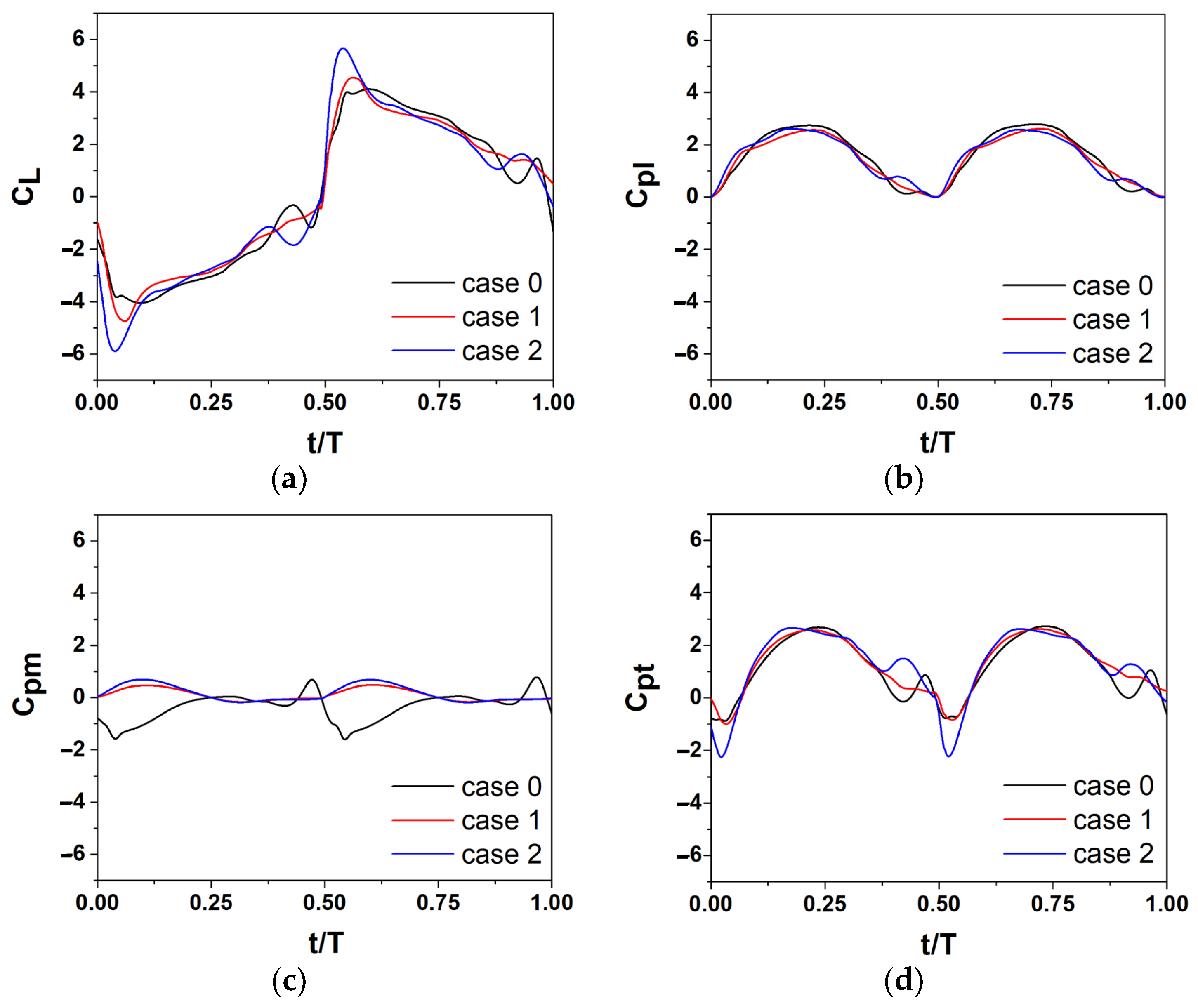
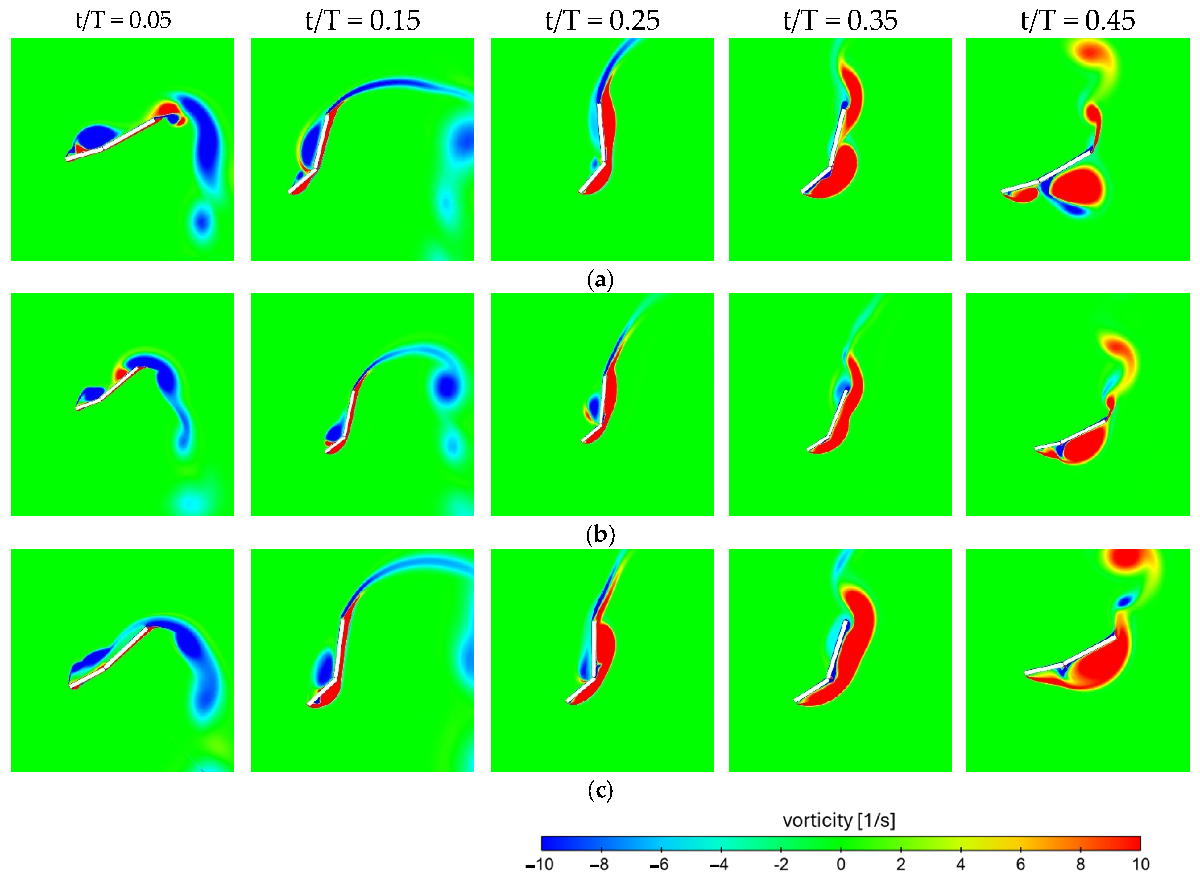
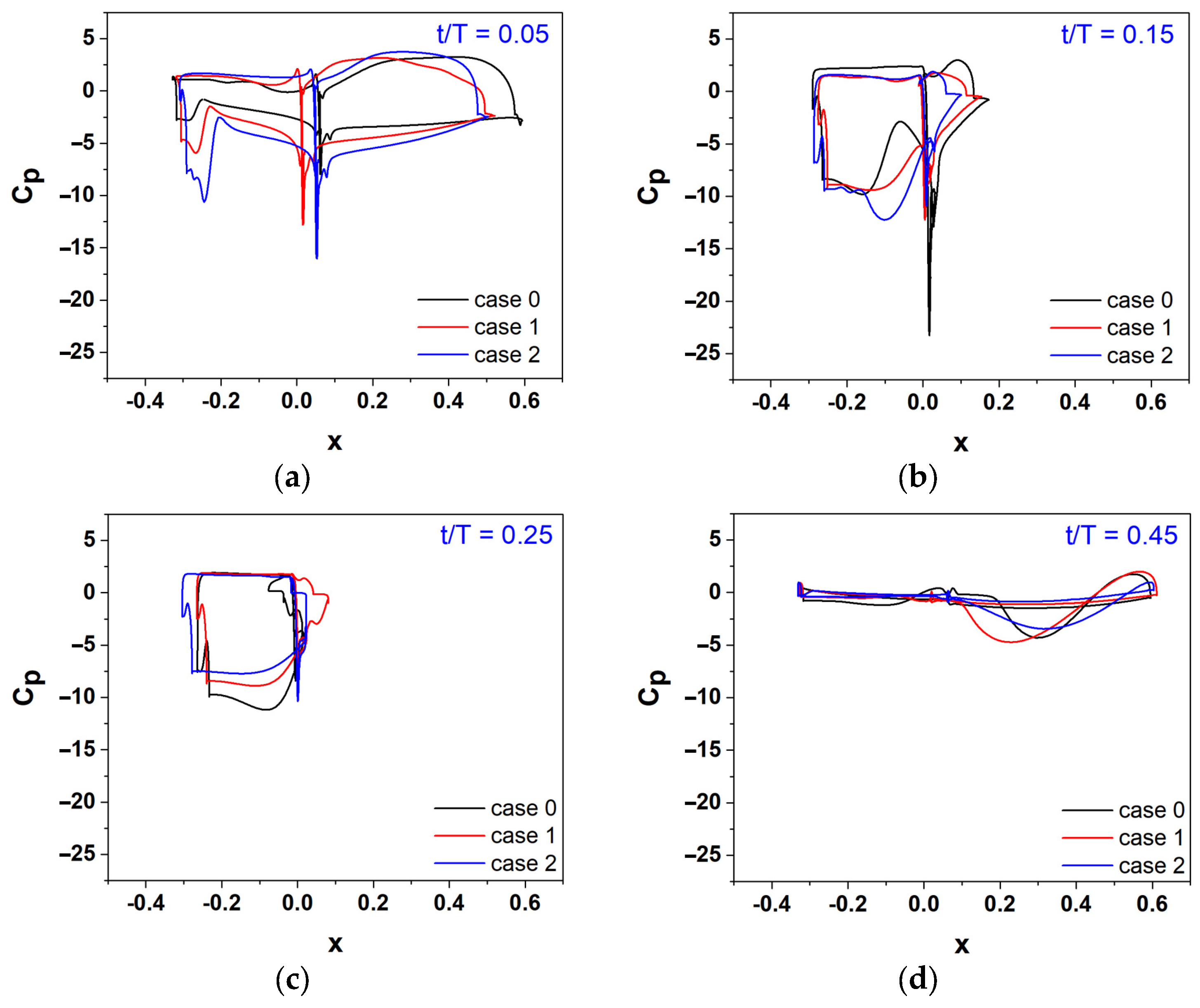
3.3. Analyzing the Three Cases in More Detail
4. Conclusions
Author Contributions
Funding
Data Availability Statement
Conflicts of Interest
Nomenclature
| Symbol | Description |
| wing thickness | |
| d | overall vertical displacement |
| x | wing projected length along x-direction |
| pitch point | |
| c | chord length |
| h | instantaneous heave amplitude |
| maximum heaving amplitude | |
| θ(t) | instantaneous pitch amplitude of the wing |
| θ0 | maximum pitch amplitude of the wing |
| instantaneous pitching amplitude of the leading flap | |
| maximum pitching amplitude of the leading flap | |
| f | oscillation frequency |
| reduced frequency (fc/U∞) | |
| ω | angular frequency |
| Reynolds number | |
| phase angle | |
| ρ | fluid density |
| free stream velocity | |
| μ | dynamic viscosity |
| pushing force coefficient | |
| moment coefficient | |
| pushing power coefficient | |
| pitching moment power coefficient | |
| total power coefficient | |
| Y(t) | pushing force |
| P | power required |
| T | time period |
| ƞ | power extraction efficiency |
References
- Jones, K.D.; Davids, S.; Platzer, M.F. Oscillating-wing Power Generator. In Proceedings of the 3rd ASME/JSME Joint Fluids Engineering Conference, San Francisco, CA, USA, 18–23 July 1999; American Society of Mechanical Engineers: New York, NY, USA, 1999. [Google Scholar]
- Shimizu, E.; Isogai, K.; Obayashi, S. Multiobjective design study of a flapping wing power generator. J. Fluids Eng. 2008, 130, 021104. [Google Scholar] [CrossRef]
- Wu, T.Y.-T. Extraction of flow energy by a wing oscillating in waves. J. Ship Res. 1972, 16, 66–78. [Google Scholar] [CrossRef]
- McKinney, W.; DeLaurier, J. Wingmill: An oscillating-wing windmill. J. Energy 1981, 5, 109–115. [Google Scholar] [CrossRef]
- Davids, S.T. A Computational and Experimental Investigation of a Flutter Generator; Naval Postgraduate School: Monterey, CA, USA, 1999. [Google Scholar]
- Kinsey, T.; Dumas, G. Parametric study of an oscillating airfoil in a power-extraction regime. AIAA J. 2008, 46, 1318–1330. [Google Scholar] [CrossRef]
- Esfahani, J.; Barati, E.; Karbasian, H.R. Fluid structures of flapping airfoil with elliptical motion trajectory. Comput. Fluids 2015, 108, 142–155. [Google Scholar] [CrossRef]
- Karbasian, H.R.; Kim, K.C. Numerical investigations on flow structure and behavior of vortices in the dynamic stall of an oscillating pitching hydrofoil. Ocean Eng. 2016, 127, 200–211. [Google Scholar] [CrossRef]
- He, G.; Yang, H.; Mo, W.; Zhao, Z.; Wang, W.; Ghassemi, H. Influence of inter-foil spacing on energy extraction of tandem oscillating hydrofoils. Ocean Eng. 2022, 259, 111953. [Google Scholar] [CrossRef]
- Dahmani, F.; Sohn, C. Effect of convergent duct geometry on the energy extraction performance of tandem oscillating hydrofoils system. J. Fluids Struct. 2020, 95, 102949. [Google Scholar] [CrossRef]
- Dahmani, F.; Sohn, C. Effects of the downstream spatial configuration on the energy extraction performance of tandem/parallel combined oscillating hydrofoils. J. Mech. Sci. Technol. 2020, 34, 2035–2046. [Google Scholar] [CrossRef]
- Wang, G.; Ng, B.F. Energy harvesting performance of a tandem-hydrofoil based closely-interconnected tidal array. Energy Convers. Manag. 2023, 280, 116796. [Google Scholar] [CrossRef]
- Xiao, Q.; Liao, W. Numerical study of asymmetric effect on a pitching foil. Int. J. Mod. Phys. C 2009, 20, 1663–1680. [Google Scholar] [CrossRef]
- Shanmugam, A.R.; Park, K.S.; Sohn, C.H. Comparison of the Power Extraction Performance of an Oscillating Hydrofoil Turbine with Different Deflector Designs. Energies 2023, 16, 3420. [Google Scholar] [CrossRef]
- Yin, B.; Luo, H. Effect of wing inertia on hovering performance of flexible flapping wings. Phys. Fluids 2010, 22, 111902. [Google Scholar] [CrossRef]
- Jiang, W.; Gao, X.; Hu, X.; Fang, D.; Chen, T.; Hou, Y. Performance Potential of Fully-passive Airborne Wind Energy System Based on Flapping Airfoil. Energy 2024, 306, 132231. [Google Scholar] [CrossRef]
- Zhu, B.; Huang, Y.; Zhang, Y. Energy harvesting properties of a flapping wing with an adaptive Gurney flap. Energy 2018, 152, 119–128. [Google Scholar] [CrossRef]
- Xie, Y.; Jiang, W.; Lu, K.; Zhang, D. Numerical investigation into energy extraction of flapping airfoil with Gurney flaps. Energy 2016, 109, 694–702. [Google Scholar] [CrossRef]
- Sun, G.; Wang, Y.; Xie, Y.; Lv, K.; Sheng, R. Research on the effect of a movable gurney flap on energy extraction of oscillating hydrofoil. Energy 2021, 225, 120206. [Google Scholar] [CrossRef]
- Zhu, F.; Li, H.; Zhang, Q.; Xie, Y.; Zhang, D. Effect of Trailing Edge Cylindrical Spoiler Structure on the Energy Harvesting Performance of the Oscillating Foil. Appl. Sci. 2024, 14, 561. [Google Scholar] [CrossRef]
- Petikidis, N.; Papadakis, G. Investigation of Submergence Depth and Wave-Induced Effects on the Performance of a Fully Passive Energy Harvesting Flapping Foil Operating Beneath the Free Surface. J. Mar. Sci. Eng. 2023, 11, 1559. [Google Scholar] [CrossRef]
- Balam-Tamayo, D.; Málaga, C.; Figueroa-Espinoza, B. Numerical study of an oscillating-wing wingmill for ocean current energy harvesting: Fluid-solid-body interaction with feedback control. J. Mar. Sci. Eng. 2020, 9, 23. [Google Scholar] [CrossRef]
- Jiang, W.; Mei, Z.; Wu, F.; Han, A.; Xie, Y.; Xie, D. Effect of shroud on the energy extraction performance of oscillating foil. Energy 2022, 239, 122387. [Google Scholar] [CrossRef]
- Hou, L.; Yang, P.; Du, D.; Zhu, B. An adaptive plate at flapping wing’s trailing edge in promoting energy extraction performance. J. Mech. Sci. Technol. 2021, 35, 591–600. [Google Scholar] [CrossRef]
- Shi, F.; Sun, X. Study on Performance Enhancement of a Flapping Foil Energy Harvester Using Circulation Control. J. Fluids Eng. 2021, 143, 071207. [Google Scholar] [CrossRef]
- MahboubiDoust, A.; Ramiar, A.; Dardel, M. Numerical investigation of plasma actuated and non-actuated Gurney flaps on aerodynamic characteristics of a plunging airfoil. Proc. Inst. Mech. Eng. Part G J. Aerosp. Eng. 2016, 230, 1423–1437. [Google Scholar] [CrossRef]
- Lee, T.; Su, Y. Unsteady airfoil with a harmonically deflected trailing-edge flap. J. Fluids Struct. 2011, 27, 1411–1424. [Google Scholar] [CrossRef]
- Visconti, U.; Eun, W.; Sim, J.; Lee, S.; Shin, S. Design improvements and flap deflection evaluations with considering centrifugal load on active trailing edge flap. Aircr. Eng. Aerosp. Technol. 2019, 91, 10–19. [Google Scholar] [CrossRef]
- He, G.; Mo, W.; Gao, Y.; Zhang, Z.; Wang, J.; Wang, W.; Liu, P.; Ghassemi, H. Modification of effective angle of attack on hydrofoil power extraction. Ocean Eng. 2021, 240, 109919. [Google Scholar] [CrossRef]
- Alam, M.; Sohn, C.H. Enhanced Performance of Oscillating Wing Energy Harvester Using Active Controlled Flap. J. Mech. Sci. Technol. 2023, 37, 2405–2415. [Google Scholar] [CrossRef]
- Alam, M.; Sohn, C.H. Parametric analysis of an oscillating wing energy harvester with a trailing edge flap. J. Mech. Sci. Technol. 2023, 37, 3563–3573. [Google Scholar] [CrossRef]
- Alam, M.; Sohn, C.H. Enhancing the Performance of an Oscillating Wing Energy Harvester Using a Leading-Edge Flap. J. Mar. Sci. Eng. 2023, 12, 62. [Google Scholar] [CrossRef]
- Lv, Z.; Zhang, G.; Sun, X. Research on energy harvesting characteristics of a flapping foil with trailing edge jet flap. Appl. Ocean Res. 2024, 146, 103951. [Google Scholar] [CrossRef]
- Liu, F.-R.; Zhang, W.-M.; Zhao, L.-C.; Zou, H.-X.; Tan, T.; Peng, Z.-K.; Meng, G. Performance enhancement of wind energy harvester utilizing wake flow induced by double upstream flat-plates. Appl. Energy 2020, 257, 114034. [Google Scholar] [CrossRef]
- Maruai, N.M.; Mat Ali, M.S.; Ismail, M.H.; Shaikh Salim, S.A.Z. Downstream flat plate as the flow-induced vibration enhancer for energy harvesting. J. Vib. Control 2018, 24, 3555–3568. [Google Scholar] [CrossRef]
- Soylak, M. Experimental investigation of aerodynamic performance of oscillating wings at low Re numbers. Proc. Inst. Mech. Eng. Part G J. Aerosp. Eng. 2016, 230, 882–1902. [Google Scholar] [CrossRef]
- Rushen, J.; Siala, F.; Totpal, A.D.; Planck, C.J.; Liburdy, J.A. The Effects of a Passively Actuated Trailing Edge on the Aerodynamics of an Oscillating Wing. In Proceedings of the Fluids Engineering Division Summer Meeting, Chicago, IL, USA, 3–7 August 2014; American Society of Mechanical Engineers: New York, NY, USA, 2014; p. V01BT12A012. [Google Scholar]
- Saleh, S.; Sohn, C.-H. Numerically Investigating the Energy-Harvesting Performance of an Oscillating Flat Plate with Leading and Trailing Flaps. Energies 2024, 17, 3010. [Google Scholar] [CrossRef]
- Mo, W.; He, G.; Wang, J.; Zhang, Z.; Gao, Y.; Zhang, W.; Sun, L.; Ghassemi, H. Hydrodynamic analysis of three oscillating hydrofoils with wing-in-ground effect on power extraction performance. Ocean Eng. 2022, 246, 110642. [Google Scholar] [CrossRef]
- Yang, H.; He, G.; Mo, W.; Wang, W. Energy Extraction Performance of Tandem Ground-Effect Hydrofoils; IOP Conference Series: Earth and Environmental Science; IOP Publishing: Bristol, UK, 2021; p. 012001. [Google Scholar]
- Zhu, B.; Zhang, J.; Zhang, W. Impact of the ground effect on the energy extraction properties of a flapping wing. Ocean Eng. 2020, 209, 107376. [Google Scholar] [CrossRef]
- Yang, H.; He, G.; Mao, W.; Mo, W.; Ghassemi, H. Blockage effect and ground effect on oscillating hydrofoil. Ocean Eng. 2023, 286, 115680. [Google Scholar] [CrossRef]
- Swain, P.K.; Dora, S.P.; Barik, A.K. Energy extraction performance of tandem flapping foil undergoing elliptical motion trajectory. Ocean Eng. 2023, 268, 113390. [Google Scholar] [CrossRef]
- Sitorus, P.E.; Ko, J.H. Power extraction performance of three types of flapping hydrofoils at a Reynolds number of 1.7 E6. Renew. Energy 2019, 132, 106–118. [Google Scholar] [CrossRef]
- Xiao, Q.; Liao, W.; Yang, S.; Peng, Y. How motion trajectory affects energy extraction performance of a biomimic energy generator with an oscillating foil? Renew. Energy 2012, 37, 61–75. [Google Scholar] [CrossRef]
- Lu, K.; Xie, Y.; Zhang, D. Nonsinusoidal motion effects on energy extraction performance of a flapping foil. Renew. Energy 2014, 64, 283–293. [Google Scholar] [CrossRef]
- Deng, J.; Teng, L.; Pan, D.; Shao, X. Inertial effects of the semi-passive flapping foil on its energy extraction efficiency. Phys. Fluids 2015, 27, 053103. [Google Scholar] [CrossRef]
- Teng, L.; Deng, J.; Pan, D.; Shao, X. Effects of non-sinusoidal pitching motion on energy extraction performance of a semi-active flapping foil. Renew. Energy 2016, 85, 810–818. [Google Scholar] [CrossRef]
- Li, W.; Wang, W.-Q.; Yan, Y.; Tian, F.-B. Effects of pitching motion profile on energy harvesting performance of a semi-active flapping foil using immersed boundary method. Ocean Eng. 2018, 163, 94–106. [Google Scholar] [CrossRef]
- Lv, Z.; Sun, X. Performance enhancement of a semi-active flapping foil energy harvester via airfoil with modified trailing edge and jet flap. Ocean Eng. 2024, 312, 119080. [Google Scholar] [CrossRef]
- Saleh, S.; Sohn, C.-H. Power Extraction Performance by a Hybrid Non-Sinusoidal Pitching Motion of an Oscillating Energy Harvester. Energies 2024, 17, 2451. [Google Scholar] [CrossRef]
- Zheng, M.; Yao, H.; Bai, Y.; Bo, Q.; Chi, X.; Chen, J. The power-extraction regime of a figure-eight trajectory flapping-foil turbine. Phys. Fluids 2024, 36, 2. [Google Scholar] [CrossRef]
- Tian, C.; Liu, X. Numerical study on the energy extraction characteristics of a flapping foil with movable lateral flaps. Renew. Energy 2024, 225, 120244. [Google Scholar] [CrossRef]
- Usoh, C.; Young, J.; Lai, J.; Ashraf, M. Numerical analysis of a non-profiled plate for flapping wing turbines. In Proceedings of the 18th Australasian Fluid Mechanics Conference, Launceston, Australia, 3–7 December 2021. [Google Scholar]
- Wang, B.; Zhu, B.; Zhang, W. New type of motion trajectory for increasing the power extraction efficiency of flapping wing devices. Energy 2019, 189, 116072. [Google Scholar] [CrossRef]
- Ansys, I. ANSYS Fluent User’s Guide; Release 2021 R1; Ansys, Inc.: Canonsburg, PA, USA, 2021. [Google Scholar]
- Kinsey, T.; Dumas, G. Computational fluid dynamics analysis of a hydrokinetic turbine based on oscillating hydrofoils. J. Fluids Eng. 2012, 134, 021104. [Google Scholar] [CrossRef]


| Mesh Type | Moving Grid Elements | Background Elements | Time Step per Oscillation | Mesh Variation (%) | Time Step Variation (%) | η (%) | |
|---|---|---|---|---|---|---|---|
| Coarse | 0.6 × | 0.3 × | 2000 | 0.891 | 34.53 | ||
| Medium | 1.2 × | 0.6 × | 500 | 0.904 | 35.03 | ||
| 2000 | 0.887 | 0.44 | 1.88 | 34.37 | |||
| 4000 | 0.883 | 0.45 | 34.22 | ||||
| Fine | 2.6 × | 1.2 × | 2000 | 0.886 | 0.11 | 34.34 |
| Setup Type | Flat Plate Without Flap [30,31] | Flat Plate Without Flap [51] | Wing With Leading Flap [32] | |
|---|---|---|---|---|
| Leading Flap | Wing | |||
| Motion type | Sinusoidal | Hybrid | Sinusoidal | Sinusoidal |
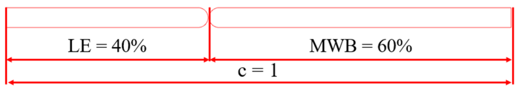
| Length percentage | 100% | 100% | 40% | 60% |
| Pitching angle | 75° | 70° | 45° | 95° |
| 0.963 | 1.16 | 1.183 | ||
| Cases | Case 0 | Case 1 | Case 2 | Case 3 |
|---|---|---|---|---|
| Leading flap | Sinusoidal | Hybrid | Sinusoidal | Hybrid |
| Wing | Sinusoidal | Hybrid | Hybrid | Sinusoidal |
| 1.544 | 1.451 | 1.403 | 1.488 | |
| −0.306 | −0.251 | −0.252 | −0.381 | |
| 1.183 | 1.200 | 1.150 | 1.106 | |
| Δ % | 1.43 | −2.78 | −6.50 | |
| η | 43.01 | 40.24 | 38.56 | 40.18 |
| Configuration Type | Flat Plate Without Flap Using Sinusoidal Motion [30,31] | Flat Plate Without Flap Using Hybrid Motion [51] | Case 1 (L35−W65) | ||
|---|---|---|---|---|---|
| Pitch angle | |||||
| 75° | 70° | 40° | 45° | 50° | |
| 0.929 | 1.047 | 1.427 | 1.474 | 1.450 | |
| 0.034 | 0.114 | −0.213 | −0.198 | −0.253 | |
| 0.963 | 1.16 | 1.213 | 1.276 | 1.196 | |
| Δ % | 20.45 | 25.96 | 32.50 | 24.19 | |
| η | 37.30 | 40.53 | 41.71 | 43.87 | 41.12 |
| Δη % | 8.65 | 11.82 | 17.61 | 10.24 | |
| Cases | Case 0 | Case 1 | Case 2 | |||
|---|---|---|---|---|---|---|
| Configuration | Leading | Wing | Leading | Wing | Leading | Wing |
| Motion type | Sinusoidal | Sinusoidal | Hybrid | Hybrid | Sinusoidal | Hybrid |
| Length percentages % | 40 | 60 | 35 | 65 | 40 | 60 |
| Pitch angle | = 45° | = 95° | = 45° | = 85° | = 50° | = 90° |
| 1.183 | 1.276 | 1.276 | ||||
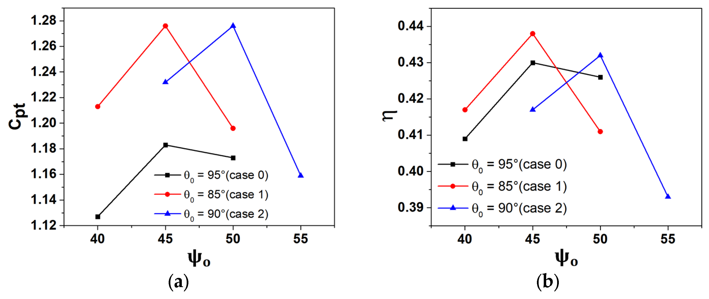
| Cases | Case 0 | Case 1 | Case 2 | ||||||
|---|---|---|---|---|---|---|---|---|---|
| Leading pitch angle | 40° | 45° | 50° | 40° | 45° | 50° | 45° | 50° | 55° |
| Cpl | 1.495 | 1.544 | 1.396 | 1.427 | 1.474 | 1.450 | 1.455 | 1.511 | 1.491 |
| Cpm | −0.368 | −0.360 | −0.222 | −0.213 | −0.198 | −0.253 | −0.223 | −0.234 | −0.332 |
| 1.127 | 1.183 | 1.173 | 1.213 | 1.276 | 1.196 | 1.232 | 1.276 | 1.159 | |
| Δ % | 2.53 | 7.86 | 1.09 | 4.14 | 7.86 | −2.02 | |||
| η | 40.98 | 43.01 | 42.65 | 41.71 | 43.87 | 41.12 | 41.79 | 43.28 | 39.31 |
| Δη | 1.99 | 0.62 | |||||||
Disclaimer/Publisher’s Note: The statements, opinions and data contained in all publications are solely those of the individual author(s) and contributor(s) and not of MDPI and/or the editor(s). MDPI and/or the editor(s) disclaim responsibility for any injury to people or property resulting from any ideas, methods, instructions or products referred to in the content. |
© 2024 by the authors. Licensee MDPI, Basel, Switzerland. This article is an open access article distributed under the terms and conditions of the Creative Commons Attribution (CC BY) license (https://creativecommons.org/licenses/by/4.0/).
Share and Cite
Saleh, S.; Sohn, C.-H. Enhanced Power Extraction via Hybrid Pitching Motion in an Oscillating Wing Energy Harvester with Leading Flap. Energies 2024, 17, 6108. https://doi.org/10.3390/en17236108
Saleh S, Sohn C-H. Enhanced Power Extraction via Hybrid Pitching Motion in an Oscillating Wing Energy Harvester with Leading Flap. Energies. 2024; 17(23):6108. https://doi.org/10.3390/en17236108
Chicago/Turabian StyleSaleh, Suleiman, and Chang-Hyun Sohn. 2024. "Enhanced Power Extraction via Hybrid Pitching Motion in an Oscillating Wing Energy Harvester with Leading Flap" Energies 17, no. 23: 6108. https://doi.org/10.3390/en17236108
APA StyleSaleh, S., & Sohn, C.-H. (2024). Enhanced Power Extraction via Hybrid Pitching Motion in an Oscillating Wing Energy Harvester with Leading Flap. Energies, 17(23), 6108. https://doi.org/10.3390/en17236108