Abstract
Hybrid-excited generators have a wide voltage regulation capability or a wide range of variable-speed constant-voltage output capability, providing a significant advantage in the new energy power generation field. To achieve the optimal design of brushless hybrid excitation synchronous generators with third harmonic excitation, it is necessary to grasp the influence of design parameters on excitation power accurately. Firstly, this paper elaborates on the structure and principle of the hybrid excitation synchronous generator. From the perspective of excitation power generation, the expression for excitation power in hybrid excitation generators has been derived, identifying the primary factors influencing excitation power, which include winding parameters, structural parameters, and magnetic circuit saturation. Secondly, qualitatively calculate the influence of the number of turns and arrangement, turns in rotor harmonic, air gap length, and thickness of the permanent magnet on the excitation power, which is verified by the electromagnetic field finite element method. The results showed that the use of full pitch and a moderate increase in turns, a decrease in air gap length, and an increase in the thickness of the permanent magnet can all increase the rotor excitation power. A brushless hybrid excitation synchronous generator prototype based on third harmonic excitation was developed, the correctness of theoretical analysis and calculation were verified by test results.
1. Introduction
With the energy crisis and environmental problems becoming increasingly prominent, efficient and environmentally friendly machine technology has become a hot spot of current research. A hybrid excitation generator combines the advantages of a smooth and adjustable air gap magnetic field of a permanent magnet generator and an electro-excitation generator [1]. It has a wide voltage regulation capability or a wide range of variable speed constant voltage output capability, which has significant advantages in the field of new energy generation. As a direct-drive wind turbine, the DC (Direct-Current) bus voltage is controlled by adjusting the electric excitation current, which can eliminate part of the high-power power electronic devices and realize the maximum capture of wind energy [2]. As a small hydro generator [3], it can improve the operating efficiency of small hydro generators and realize the efficient use of water resources, in addition, the hybrid excitation hydro generator is convenient and rapid to start the excitation and does not need to be configured with a special starting power supply, which is more suitable to be used as a black-start power source for the local power grid.
However, the excitation windings of some hybrid excitation machines are still arranged on the rotor, requiring mechanical devices such as brushes and slip rings to input the excitation current, thus losing the advantages of brushless permanent magnet machines [4]. Harmonic excitation can be a better solution to the problem of brushless machines [5,6,7]. Researchers in [8,9] use the harmonic magnetic field established by the harmonic magnetic potential generated by the armature winding, which induces a harmonic electromotive force in the rotor harmonic winding, which is rectified by a diode to provide the rotor excitation winding with a DC current for excitation. Reference [10] utilizes the tooth harmonic magnetic field generated by stator slotting to induce a tooth harmonic electromotive force in the rotor harmonic winding, rectified by a diode to provide an excitation current to the generator excitation winding. These harmonic excitation methods are applied to electro-excited synchronous generators, which have problems such as difficulty in starting excitation and insufficient excitation power. Researchers in [11] applied harmonic excitation to a hybrid excitation synchronous generator due to the existence of permanent magnets, and the electro-excitation magnetic potential is only for auxiliary regulation, it has the advantages of rapid voltage build-up and small required excitation power. Reference [12] is to arrange a set of harmonic windings in the stator and rotor of the hybrid excitation generator, respectively, and realize the direct transmission of the excitation power from the stator to the rotor through the magnetic field coupling relationship between the harmonic windings. However, the harmonic magnetic field of this scheme is generated by the stator harmonic excitation windings instead of the harmonic magnetic field inherent in the machine.
The harmonic magnetic fields in the machine exist objectively, and among these harmonic magnetic fields, the third harmonic has the largest amplitude. As early as the 1970s, scholars in China conducted a preliminary study on the basic principles of third harmonic excitation, which was quickly applied to small and medium-sized electrically excited synchronous generators [13]. This harmonic excitation method has the advantages of self-excited constant voltage characteristics within a certain load range and good dynamic performance [14]. Reference [15] based on the problems of insufficient excitation capacity and insufficient voltage regulation amplitude of the armature winding, according to the spatial distribution of the magnetic field in the air gap, slots are used on the surface of the magnetic poles to increase the third harmonic magnetic field component, to increase the excitation power of the harmonic generator, and to improve the starting excitation performance of the machine, but with an adverse effect on the intrinsic voltage regulation rate. Reference [16] explores the effect of pole tip saturation on the stator harmonic winding electromotive force in convex-pole synchronous generators. Due to the structure of the convex pole synchronous machine is characterized by a thinner magnetic circuit at the pole tip, resulting in the pole tip part of the pole being more likely to reach the magnetic saturation state during the excitation process compared to the pole top part, so the magnetic density of the pole tip part of the pole grows at a slower rate, which makes the third harmonic density in the air gap of the machine decreases with the increase of the excitation current. It has been shown that many factors, such as the winding, magnetic circuit structure, and the degree of magnetic circuit saturation, greatly influence the third harmonic magnetic field. Reference [17] explores the effect of design parameters on hybrid excitation generators, the key design parameters, such as slot-pole combinations, stack lengths, and armature winding turns, are determined to ensure generator open-circuit voltage limitation. Reference [18] explores the influence of design parameters on the performance of brushless electrically excited synchronous reluctance generators, the effect of different pole combinations and rotor sizes on the magnetic coupling capability of this machine was specifically addressed through offline testing of a prototype with a magnetic barrier reluctance rotor and a new hybrid cage rotor with superior performance.
The group applied the third harmonic to a hybrid excitation generator to form a third harmonic brushless excitation scheme [19,20]. In this scheme, the third harmonic windings are placed on the stator, and the harmonic windings with the same pitch as the stator’s third harmonic windings are arranged on the rotor to induce harmonic electromotive force. As shown in Figure 1, when the machine is running, the third harmonic magnetic field in the air gap induces the third harmonic electromotive force in the stator third harmonic winding. When the stator third harmonic winding circuit is switched on, the current flowing in its winding generates the air gap harmonic magnetic field. This harmonic magnetic field induces a harmonic electromotive force in the harmonic winding, which is rectified to provide an excitation current to the excitation winding. Therefore, this hybrid excitation generator transfers the energy from the stator side to the rotor side through the magnetic field coupling relationship between the stator and rotor harmonic windings, realizing a brushless machine. The topology, operating principle, harmonic excitation principle, design, and performance calculations of the third harmonic brushless hybrid excitation synchronous generator are investigated around the third harmonic hybrid excitation synchronous generator.
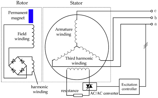
Figure 1.
Schematic diagram of third harmonic brushless hybrid excitation generator.
To realize the optimized design of this hybrid excitation generator, it is necessary to accurately grasp the influence of the machine design parameters on the excitation power and find the sensitive parameters affecting the excitation power. The finite element model of the third harmonic brushless hybrid excitation generator is established to calculate the influence of winding parameters, structural parameters, etc., on the excitation power and to obtain the operating characteristics of harmonic winding and the change rule of machine parameters and excitation power.
2. Analysis of the Influence of Machine Parameters on Excitation Power
The hybrid excitation generator excitation power is obtained by the air gap third harmonic magnetic field inducing harmonic electromotive force in the stator third harmonic windings and by electromagnetic induction between the stator and rotor harmonic windings. Because the third harmonic magnetic field is affected by many factors such as magnetic circuit structure, magnetic circuit saturation, structural parameters, and windings, and the electromagnetic relationship between the windings of this machine is complicated. To grasp the matching between the third harmonic and the excitation power, the factors affecting the excitation power in the third harmonic brushless hybrid excitation generator need to be analyzed in detail when designing and developing this kind of machine.
2.1. Mathematical Expression of Stator Third Harmonic Winding Current
According to the schematic diagram of this third harmonic brushless hybrid excitation synchronous generator and its working principle, a simplified diagram of the stator third harmonic winding circuit of this machine can be obtained, as shown in Figure 2, where Esh is the stator third harmonic winding induced electromotive force, Ush is the stator third harmonic winding voltage, Xsh is the stator third harmonic winding reactance, Rsh is the stator third harmonic winding resistance, Rsh is the adjustable resistance, rsh is the adjustable resistance, and Ish is the stator third harmonic winding current.
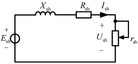
Figure 2.
Simplified diagram of stator third harmonic winding.
The excitation power of the hybrid excitation generator is actually provided by the stator third harmonic winding, and the expression for the induced electromotive force in the stator third harmonic winding is as follows:
In the formula, f3 denotes the stator third harmonic winding electric potential frequency, its frequency is three times the frequency, denotes the third harmonic flux per pole, N3 is the stator third harmonic winding series turns, and Kdp3 is the stator third harmonic winding factor. τ3 represents the stator third harmonic winding pitch, the value of one-third of the fundamental pitch, and B3 is the third harmonic magnetic density.
The stator third harmonic winding current expression is as follows:
From Equation (2), it can be seen that for the stator third harmonic current, its value is related to the stator third harmonic winding reactance and resistance under the condition of constant external resistance.
The resistance of the stator third harmonic winding resistance and its turns N3 are linearly related, while the third harmonic winding reactance can be expressed as follows:
In the formula, λ0 is average air gap permeability, D is the machine rotor diameter, l is the machine core length, δ is the air gap length, kμ is the saturation coefficient, P3 is the third harmonic magnetic field pole-to-pair, and its value is three times of the machine fundamental pole-to-pair P.
It can be seen that the number of turns in the stator third harmonic winding will greatly affect the output power of the stator third harmonic winding. When the number of turns changes, the induced electromotive force and current of the stator third harmonic winding will also change, thereby affecting the harmonic magnetic force generated by the stator third harmonic winding current in the air gap and the harmonic magnetic field established, ultimately leading to changes in the induced electromotive force and current of the rotor harmonic winding, and the corresponding excitation power will also change.
2.2. Mathematical Expression of Rotor Excitation Power
When the rotor harmonic winding resistance is ignored, the rotor harmonic winding excitation source can be equivalent to a voltage source and reactance in series. To analyze the influence of the rotor harmonic winding on the excitation power and to solve for its maximum excitation power, the equivalent circuit of the rotor harmonic excitation system at this time can be simplified, as shown in Figure 3.
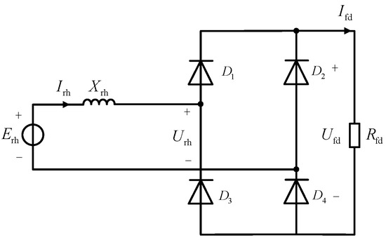
Figure 3.
Equivalent circuit diagram of rotor harmonic excitation system.
Erh is the induced electromotive force of the rotor harmonic winding, which can be obtained by finite element calculation of the machine magnetic field and post-processing; Xrh is the reactive resistance of the rotor harmonic winding, Irh is the rotor harmonic winding current, Urh is the rotor harmonic winding voltage, Rfd is the excitation winding resistance, Ufd is the excitation winding voltage, Ifd is the excitation winding current. When the influence of the rotor harmonic winding resistance and its reactance is neglected, but the voltage drop caused by the phase change reactance of the rectifier circuit is considered, the average value of the excitation current is:
In the formula is the average value of the rectified voltage, and the phase change voltage drop expression is calculated according to the knowledge of power electronics:
Substituting into Equation (4) gives the excitation current:
According to Equation (6), the rectifier circuit can be equated as shown in Figure 4, where XB represents the dirent-current equivalent resistance of the commutator reactance.
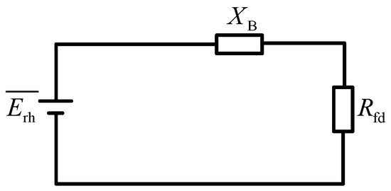
Figure 4.
Equivalent diagram of rectification circuit.
When the number of turns of the rotor harmonic winding of the machine is increased, the induced electromotive force of the rotor harmonic winding increases proportionally, and the value of the reactance of the rotor harmonic winding increases by the square multiple of the number of its turns. When the DC equivalent resistance of the rotor harmonic winding is not equal to that of the excitation winding, the change in the number of turns of the rotor harmonic winding affects the excitation power. When the DC equivalent resistance of the rotor harmonic winding is less than the excitation winding resistance, the increase with the increase in the number of turns will be greater than the increment on the DC equivalent resistance, and thus, the excitation power will increase, while when the DC equivalent resistance of the rotor harmonic winding is greater than the resistance of the excitation winding, the increase with the increase in the number of turns will be less than the increment on the DC equivalent resistance, and the output of the excitation power will be reduced instead.
The relationship between the induced electromotive force Erh of the rotor harmonic winding in the machine and the number of rotor harmonic winding turns Nh and the third harmonic flux is:
In the formula, fh is the rotor harmonic winding frequency, its frequency is six times the industrial frequency, Kdph is the rotor harmonic winding factor, and harmonic flux per pole is generated by the stator third harmonic winding current. Combined with the relationship between the magnetic flux and the magnetic density, this can be expressed in Equation (8) as follows:
In the formula, Fshm is the amplitude of the third harmonic magnetic potential, is the rotor harmonic winding pitch, and the value of one-third of the pole pitch , according to the knowledge of the rectifier circuit, can be obtained after the rectification of the rotor harmonic winding; rectification of the average value is as follows:
In the formula, Kd is the rectification coefficient, and its value is 0.9.
Substituting Formulas (9) and (10) into Formula (6) yields the expression for the excitation current as follows:
The excitation power Pfd output from the rotor side is the product of the average value of the rectified voltage and the excitation current, which can be expressed as follows:
From Equation (12), it can be seen that the excitation power output from the rotor side is related to a number of factors, such as the number of turns of the stator third harmonic windings and their arrangement, the machine diameter, the core length, the air-gap length, the magnetic circuit structure, the saturation of the magnetic circuit, and the number of turns of the rotor harmonic windings as well as the excitation windings.
3. Calculation of the Influence of Parameters on the Excitation Power
To further study the performance of this hybrid excitation generator, the simulation software Maxwell is used to establish the machine model and calculate the electromagnetic field. The mesh sectional diagram and the simulation circuit of the third harmonic brushless hybrid excitation synchronous generator are shown in Figure 5 and Figure 6 separately. Quantitative calculations are carried out for the influencing factors of the excitation power.
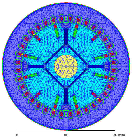
Figure 5.
Mesh Sectional Diagram of hybrid excitation synchronous generator.
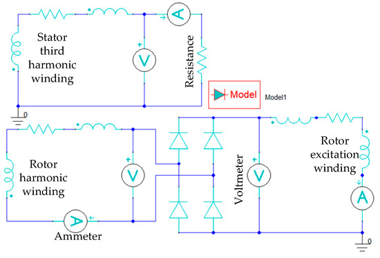
Figure 6.
Simulation circuit of the third harmonic excitation system.
3.1. The Influence of Third Harmonic Winding Turns on Excitation Power
As can be seen from the Equation (13), the electromotive force generated by the stator third harmonic winding is proportional to the number of turns of the third harmonic winding, and as the number of turns of the stator third harmonic winding continues to increase, the induced electromotive force induced by the stator third harmonic winding increases, but at the same time, the stator third harmonic winding resistance and reactance are also increasing, and reactance increases proportionally to the square of the number of turns, which results in the relative decrease in the magnitude of the increase in the rotor excitation current and the excitation power. Therefore, although the increase in the number of turns theoretically increases the third harmonic winding-induced electromotive force linearly, the increase in the harmonic excitation power obtained from the stator side is not linear. In order to verify the effect of the change in the number of turns of the third harmonic winding on the rotor excitation power, the simulation calculates the increase in the number of turns of the third harmonic winding of the stator from 16 to 30 turns during the no-load operation of the generator and obtains the changes in the stator third harmonic winding voltage and current and the excitation winding voltage and current, and the simulation results are shown in Table 1.

Table 1.
Simulation results of stator third harmonic winding with different turns.
Table 1 shows that when the number of turns of the stator third harmonic winding increases gradually, the stator third harmonic winding voltage rises from 41.27 V to 50.30 V, with an increase of 21.88%, the excitation current increases from 1.32 A to 2.47 A, and the excitation power rises from 13.63 W to 41.55 W. However, as the number of turns increases uniformly, the stator third harmonic winding voltage rises from 1.32 A to 2.47 A, and the excitation power increases from 13.63 W to 41.55 W due to the increase of the reactance of the third harmonic winding. However, as the number of turns increases uniformly, due to the increase of the third harmonic winding reactance, the increase of the stator third harmonic winding voltage also decreases, and the stator third harmonic winding voltage basically does not change after 26 turns. Therefore, the number of turns of the stator third harmonic winding is not the larger, the better, but also takes into account the machine slot full rate and heat loss.
3.2. The Influence of Third Harmonic Winding Arrangement on Excitation Power
With the total number of turns kept constant, the effect of the stator third harmonic winding arrangement on the excitation power is investigated, and four different winding arrangements are designed.
The first scheme is the stator third harmonic winding arrangement with whole pitch; the number of turns is set to 10 turns per turn, and the machine cross-section and winding arrangement under this scheme are shown in Figure 7.
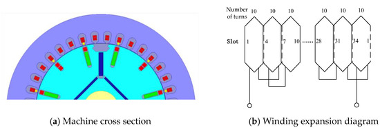
Figure 7.
The stator third harmonic winding is arranged in a full pitch arrangement.
The second scheme is arranged by using a 2/3 short pitch and the number of winding turns is set to 10 turns per turn; the machine cross-section and winding arrangement diagram under this scheme are shown in Figure 8.
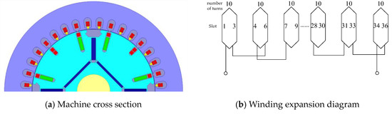
Figure 8.
The stator third harmonic winding is arranged in a 2/3 short distance arrangement.
The third scheme is concentric distribution, both inner and outer windings are set to 5 turns to ensure that the total number of turns remains the same, the machine cross-section and winding arrangement diagram under this scheme is shown in Figure 9.
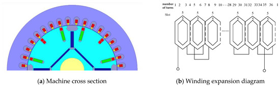
Figure 9.
The stator third harmonic winding is concentric (same number of turns for inner and outer windings).
The fourth scheme is based on the third concentric type and changes the inner and outer turns ratio; the outer turns are set to four turns, the inner circle is set to six turns to ensure that the total number of turns remains unchanged; the scheme under the winding arrangement shown in Figure 10.
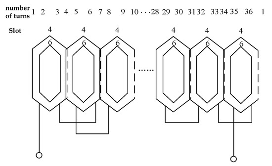
Figure 10.
The stator third harmonic winding is concentric (the number of turns in the inner and outer windings differs).
For the stator third harmonic winding four different arrangements of no-load electromagnetic field calculations, the simulation process of the stator third harmonic winding open-circuit, the excitation system is not accessed to observe the stator third harmonic winding induced electromotive force size and waveforms, induced electromotive force waveforms are shown in Figure 11.
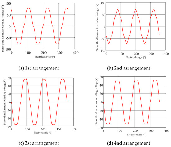
Figure 11.
The waveform of electromotive force of stator third harmonic winding under four arrangement modes.
As can be seen from Figure 11, the induced electromotive force of the third harmonic winding under four different arrangements is different, and the excitation power it provides at the rotor side will also be different. At this time, the stator third harmonic winding circuit is turned on, and the rotor third harmonic winding passes through the rectifier bridge to supply power to the excitation winding and the simulation results are shown in Table 2.
Table 2.
Simulation results of different arrangements of stator third harmonic windings.
When the total number of turns does not change, the stator third harmonic winding induces the maximum electromotive force under the 1st arrangement scheme, and it can be seen from Table 2 that the voltage and current of the stator third harmonic winding are also the maximum at this time, and the rotor excitation winding voltage and current are higher than those of other arrangement schemes, and the excitation power of the 2nd, 3rd, and 4th arrangement schemes are 69.67% of the 1st arrangement scheme, respectively 45.67%, and 36.44% respectively.
3.3. The Influence of Rotor Harmonic Winding Turns on Excitation Power
When the stator third harmonic winding flows current, the resulting alternating harmonic magnetic field passes through the air gap, intersects the rotor side harmonic winding, and induces the corresponding harmonic electromotive force. When the rotor harmonic winding turns are different, the induced rotor harmonic electric potential will also be different and thus will also have an impact on the excitation power. Simulation is carried out for different turns of the rotor harmonic winding during the no-load operation of the generator to calculate the changes in rotor harmonic winding voltage and current, rotor excitation winding current, and excitation power, and the simulation results are shown in Figure 12.
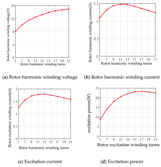
Figure 12.
Simulation results of rotor harmonic winding with different turns.
As can be seen from Figure 12, with the increase in the number of rotor harmonic winding turns, the rotor harmonic winding voltage is an upward trend, but the harmonic winding reactance increases more, so the upward trend is becoming smaller. While the rotor harmonic current, the excitation current, and the excitation power, with the increase in the number of turns of the rotor harmonic winding, appeared to be first upward and then downward trending, which is due to the process of increasing the number of turns of the rotor harmonic winding, the resistance will be linearly increased. This is because the resistance of the rotor harmonic winding increases linearly during the increase in the number of turns, and the reactance increases with the square multiple of the number of turns and when the number of turns is increased to the point where the DC equivalent resistance is equal to the resistance of the excitation winding, and then the number of turns of the rotor harmonic winding is increased, the excitation power decreases.
When the excitation power is in the rising stage, due to the rotor harmonic winding resistance and reactance, the rate of rise of the excitation power will be gradually reduced. Therefore, as with the stator third harmonic winding, the rotor harmonic winding turns are not the larger, the better; when the rotor harmonic winding turns increase linearly, its acquisition of the excitation power does not increase linearly in proportion.
3.4. The Influence of Air Gap Length on Excitation Power
In this section, no-load simulations are carried out for different air gap lengths to analyze the effect on the excitation power when the air gap length is increased from 0.8 mm to 1.5 mm.
In Figure 13a–c show the waveforms of the machine air gap magnetization at air gap lengths of 0.8 mm, 1.2 mm, and 1.5 mm, respectively.
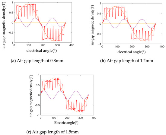
Figure 13.
Distribution map of air gap magnetic density at different air gap lengths.
The FFT (Fast Fourier Transform) decomposition of the magneto–density waveform plots at different air gap lengths yields the fundamental magneto–density amplitude as well as the third harmonic magneto–density amplitude, as shown in Table 3.
Table 3.
FFT decomposition results of magnetic density waveforms at different air gap lengths.
From Figure 13 as well as Table 3, it can be seen that under the condition of constant excitation magnetomotive force, the air gap magnet magnetism decreases with the increase of the air gap length, which will then have an effect on the generator excitation power, and the simulation results are shown in Figure 14.
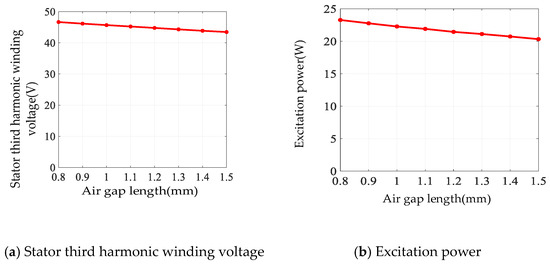
Figure 14.
Simulation results of different air gap lengths under uniform air gap.
As can be seen from Figure 14, as the air gap length gradually increases from 0.8 mm to 1.5 mm, the stator third harmonic winding voltage 46.66 V decreases to 43.46 V, and the rotor harmonic winding voltage also decreases from 13.93 V to 12.58 V. As the voltage decreases, the currents of the rotor third harmonic winding and the excitation winding are also decreased, and the excitation power is reduced from 23.28 W to 20.33 W, with a reduction of 12.67%. Therefore, the air gap length is minimized in the design.
3.5. The Influence of Permanent Magnet Thickness on Excitation Power
The rotor permanent magnet slot of the hybrid excitation generator has tangentially and radially magnetized permanent magnets, whose parameter changes will have a direct effect on the air gap magnetic field, and the excitation power will also be affected.
For the radial magnetization permanent magnet thickness of 2, 3, 4, 5, and 6 mm, corresponding to the tangential magnetization permanent magnet thickness of 4, 6, 8, 10, and 12 mm simulation calculations, respectively, take a pair of under-pole magnetization spatial distribution of the FFT decomposition to get the fundamental magnetization amplitude and the third harmonic magnetization amplitude, as shown in Table 4.
Table 4.
FFT decomposition results of air gap magnetic density waveform.
From Table 4, it can be seen that with the increase in the thickness of the permanent magnet, the air gap fundamental magnetization increases from 0.8184 T to 0.9982 T, an increase of 21.97%, and the third harmonic magnetization increases from 0.1879 T to 0.2693 T, an increase of 43.32%, both of which have a relatively large increase. With the increase of air gap magnetization, the simulation results are shown in Figure 15.
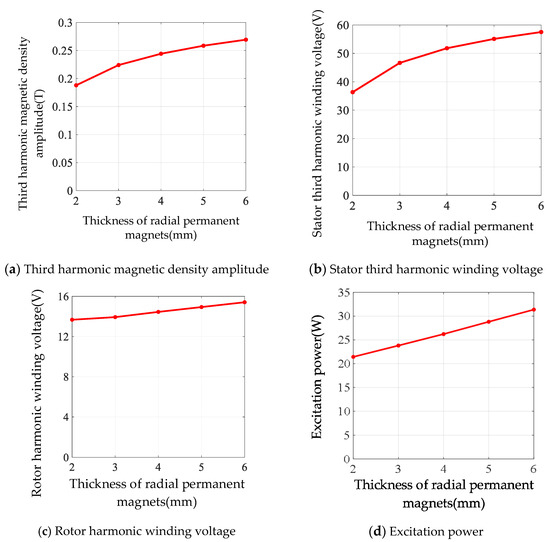
Figure 15.
Simulation results of different thicknesses of permanent magnets.
From Table 4 and Figure 15, it can be seen that when the thickness of the radial magnetized permanent magnet increases from 2 mm to 6 mm, the fundamental magnetization amplitude as well as the third harmonic magnetization amplitude increases, which causes the stator third harmonic winding voltage to increase from 36.34 V to 57.52 V, the stator third harmonic winding current to increase from 6.38 A to 10.09 A, and the excitation power to increase from 21.43 W to 31.37 W. Therefore, as the thickness of the permanent magnet increases, the excitation power increases, and the ability of the machine to resist demagnetization increases, but it leads to an increase in the cost of the machine.
4. Experimental Validation
Based on the above theoretical analysis and calculation, an optimal design scheme is obtained. The structural parameters of the third harmonic brushless hybrid excitation synchronous generator are determined, and a generator prototype is developed, whose main parameters are shown in Table 5, and a prototype test platform is built, as shown in Figure 16, where the prototype rotor punch diagram is shown in Figure 17.
Table 5.
Main parameters of the brushless hybrid excitation synchronous generator based on harmonic excitation.
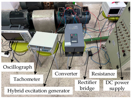
Figure 16.
Test platform of third harmonic brushless hybrid excitation synchronous generator prototype.
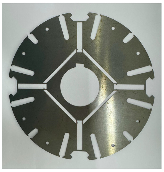
Figure 17.
Rotor punch diagram.
The armature winding line voltage waveforms and the third harmonic winding voltage waveforms during the no-load operation of the hybrid-excited generator were tested, as shown in Figure 18.
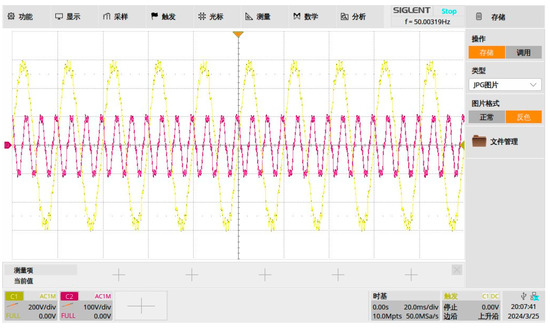
Figure 18.
Waveforms of armature winding wire voltage and stator third harmonic voltage.
Figure 18 shows the waveforms of armature winding line voltage and stator third harmonic winding voltage intercepted from the oscilloscope for 200 ms; it can be seen that the waveforms experienced 10 cycles and 30 cycles, respectively, in 200 ms, so the frequency of the armature winding line voltage waveform is 50 Hz, and the frequency of the stator third harmonic winding voltage waveform is three times of the frequency of the armature winding line voltage waveform, and the experimental results verified the theoretical analysis.
To verify the performance of the harmonic brushless excitation system, the stator third harmonic winding is connected with a resistor in series and forms a circuit, the harmonic winding lead wire on the rotor side is rectified by a diode rectifier bridge and connected with the excitation winding lead wire, the external resistor is adjusted to control the stator third harmonic winding current, and when the stator third harmonic current is varied, the changes of the armature winding line voltage, the rotor harmonic winding current and the excitation current are observed. The experimental results are shown in Table 6 and Figure 19.
Table 6.
Experimental results when the harmonic brushless excitation system works.
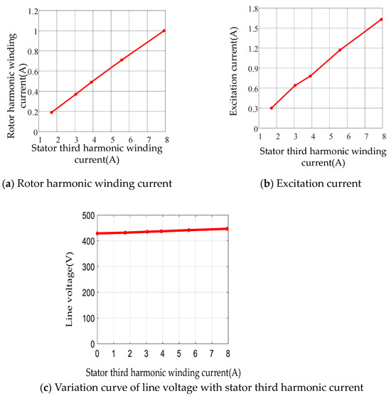
Figure 19.
Test results of third harmonic brushless excitation system.
As seen in Table 6 and Figure 19, as the stator third harmonic current increases from 1.71 A to 7.93 A, the rotor harmonic voltage increases from 6.58 V to 15.15 V, the rotor harmonic current increases from 0.19 A to 1.00 A, the rotor excitation current increases from 0.30 A to 1.63 A, and the armature line voltage increases from 431.73 V to 446.80 V, which is an increase of 3.49%, indicating that this harmonic brushless excitation system has a good regulation effect.
5. Conclusions
A study was conducted on the influence of parameters on the excitation power of a third harmonic brushless hybrid excitation generator, including the following parts:
- (1)
- Starting from the mechanism of excitation power generation, the expression of excitation power for hybrid excitation generators was derived, and the main factors affecting excitation power were obtained, including winding parameters, structural parameters, and magnetic circuit saturation.
- (2)
- A simulation model of a hybrid excitation generator was established, and different factors affecting the excitation power of the generator were simulated and calculated separately. When the number of turns of the stator third harmonic winding increases linearly, the excitation power output on the stator side will also increase. Four different arrangements of stator third harmonic windings were designed, and simulation results showed that the first arrangement could achieve greater stator third harmonic induced electromotive force and excitation power. When the number of turns of the rotor harmonic winding increases, the excitation power first increases and then decreases. When the air gap of the machine is uniform, the larger the air gap length, the smaller the excitation power. Simulations were conducted on different thicknesses of permanent magnets, and it was found that as the thickness of the permanent magnet increases, the excitation power also increases.
- (3)
- A prototype of a hybrid excitation generator based on the third harmonic was developed, and an experimental testing platform was built to test the machine. The no-load characteristics of the machine and the performance of the harmonic brushless excitation system were tested, and the experimental results verified the correctness of the theoretical analysis and the performance of the harmonic brushless excitation system.
Author Contributions
Supervision, writing—review and editing, Y.X.; Theoretical derivation, simulation calculations and writing—original draft preparation, J.X. and J.H.; Theoretical calculation, guidance and experimental testing Y.C. and J.Z.; Development of the prototype, Y.Y. All authors have read and agreed to the published version of the manuscript.
Funding
Thank the support of the National Natural Science Foundation of P.R. China (No. 52067015).
Data Availability Statement
The datasets used or analysed during the current study are available from the corresponding author on reasonable request.
Conflicts of Interest
Author Yu Yeguo was employed by the company Kangfu Sci-tech Co., Ltd. The remaining authors declare that the research was conducted in the absence of any commercial or financial relationships that could be construed as a potential conflict of interest.
References
- Zhuoran, Z.; Dong, W.; Wei, H. Overview of configuration, design and control technology of hybrid excitation machine. Proc. CSEE 2020, 40, 7834–7850. [Google Scholar]
- Meihua, Z.; Yong, Y.; Qinhong, Z. Tracking the peak power points for a wind energy conversion system based on hybrid excited synchronous generator. Trans. China Electrotech. Soc. 2013, 28, 30–36. [Google Scholar]
- Kamiev, K.; Parviainen, A.; Pyrhönen, J. Hybrid excitation synchronous generators for small hydropower plants. In Proceedings of the XXII International Conference on Electrical Machines, Lausanne, Switzerland, 4–7 September 2016; pp. 2529–2535. [Google Scholar]
- Hoang, E.; Lecrivain, M.; Gabsi, M. A new structure of a switching flux synchronous polyphased machine with hybrid excitation. In Proceedings of the European Conference on Power Electronics and Applications, Aalborg, Denmark, 2–5 September 2007; pp. 1–8. [Google Scholar]
- Nonaka, S.; Kesamaru, K.; Horita, K. Analysis of brushless four-pole three-phase synchronous generator without exciter by the finite element method. IEEE Trans. Ind. Appl. 1994, 30, 615–620. [Google Scholar] [CrossRef]
- Shibata, F.; Kohrin, T. A brushless, self-excited single-phase synchronous generator operating with load and exciting currents flowing in armature. IEEE Trans. Energy Convers. 1987, 2, 254–261. [Google Scholar] [CrossRef]
- Lizhi, S.; Xiaolong, G.; Fei, Y.; Quntao, A.; Lipo, T.A. A new type of harmonic-current-excited brushless synchronous machine with open windings. Trans. China Electrotech. Soc. 2015, 30, 96–103. [Google Scholar]
- Fukami, T.; Hanada, Y.; Miyamoto, T. Analysis of the self-excited three-phase synchronous generator utilization the second space harmonic for excitation. Electr. Eng. Jpn. 1997, 121, 70–81. [Google Scholar] [CrossRef]
- Inoue, K.; Yamashita, H.; Nakamae, E.; Fujikawa, T. A brushless self-exciting three-phase synchronous generator utilizing the 5th-space harmonic component of magneto motive force through armature currents. IEEE Trans. Energy Convers. 1992, 7, 517–524. [Google Scholar] [CrossRef]
- Houxian, H.; Juan, T. Calculation for harmonic winding potential of tooth harmonic brushless exciting generator. J. Nanchang Coll. Water Conserv. Hydroelectr. Power 1999, 18, 31–33. [Google Scholar]
- Yonghong, X.; Lin, Z.; Mingming, W.; Zandao, J.; Ying, C.; Yongkang, X. Design research of harmonic brushless excitation system for hybrid excitation generator. Electr. Mach. Control. 2023, 27, 73–84. [Google Scholar]
- Yonghong, X.; Lin, Z.; Shanming, W.; Zhichao, Z.; Ying, C.; Jingming, Z. Structure and principle for hybrid excitation synchronous generator with additional harmonic windings. Proc. CSEE 2020, 40, 7880–7889. [Google Scholar]
- Jie, Y. The application of triple frequency harmonic excitation on the diesel generator set. Technol. Dev. Enterp. 2014, 33, 28–29. [Google Scholar]
- Jiji, K.S.; Jayadas, N.H.; Babu, C.A. FEM-based virtual prototyping and design of third harmonic excitation system for low-voltage salient-pole synchronous generators. IEEE Trans. Ind. Appl. 2014, 50, 1829–1834. [Google Scholar] [CrossRef]
- Department of Electrical Engineering, Jiangxi University of Technology. Analysis of Increasing Excitation Capacity of Third Harmonic Generator by Changing Magnetic Pole Shape. Electr. Mach. Control. Appl. 1975, 1, 32–34. [Google Scholar]
- Shaogang, H.; Yonghong, X.; Longquan, X. Effect of magnetic saturation on no-load harmonic property of synchronous generators by the third harmonic excitation. Micromotors 2008, 10, 10–11. [Google Scholar]
- Sun, L.; Zhang, Z.; Yu, L.; Gu, X.; Vansompel, H.; Sergeant, P. Design and analysis of hybrid excitation generators for aircraft applications under limiting open-circuit voltage. IEEE Trans. Transp. Electrif. 2022, 8, 3390–3400. [Google Scholar] [CrossRef]
- Zhang, F.; Wang, H.; Jia, G.; Ma, D.; Jovanovic, M.G. Effects of design parameters on performance of brushless electrically excited synchronous reluctance generator. IEEE Trans. Ind. Electron. 2018, 65, 9179–9189. [Google Scholar] [CrossRef]
- Zhichao, Z. Performance Calculation of Brushless Hybrid Excitation Generator Based on Third Harmonic. Master’s Thesis, Nanchang University, Nanchang, China, June 2021. [Google Scholar]
- Xia, Y.; Huang, H.; Zhu, Z.; Guo, H.; Chen, Y. Brushless excitation principle and experimental verification of hybrid excitation synchronous generator based on harmonic magnetic field. IEEE Access 2022, 10, 85146–85153. [Google Scholar] [CrossRef]
Disclaimer/Publisher’s Note: The statements, opinions and data contained in all publications are solely those of the individual author(s) and contributor(s) and not of MDPI and/or the editor(s). MDPI and/or the editor(s) disclaim responsibility for any injury to people or property resulting from any ideas, methods, instructions or products referred to in the content. |
© 2024 by the authors. Licensee MDPI, Basel, Switzerland. This article is an open access article distributed under the terms and conditions of the Creative Commons Attribution (CC BY) license (https://creativecommons.org/licenses/by/4.0/).