2. Thermal Energy Storage—Methods and Materials
Efficient thermal energy storage is a key element of systems based on renewable energy sources, such as solar thermal systems. It allows excess heat generated during the day to be accumulated and used at times when solar energy is less available, such as at night. The choice of an appropriate storage method and materials plays a critical role in minimizing energy losses and ensuring the thermal stability of the systems. This chapter discusses the main thermal energy storage methods and the characteristics of the materials used in such technologies, taking into account their thermal properties and practical applications.
2.1. Types of Thermal Energy Storage
In addition to the proper selection of system components, effective thermal energy storage is crucial for the efficient operation of a solar system. There are several types of thermal energy storage, as categorized by the authors of publication [
11].
The basic division includes two main categories: thermal and chemical energy storage.
Thermal storage is further divided into the following two main types:
- -
Sensible heat storage, which can occur in liquids and solids.
- -
Latent heat storage, which occurs during phase changes such as solid–liquid, liquid–gas, and solid–solid.
Chemical storage, on the other hand, involves the following:
- -
The use of chemical reactions (heat of reaction).
- -
Heat pumps.
- -
Thermal chemical pipelines (heat pipes), which can transfer heat in the form of steam or other heating media, thereby supporting chemical or energy processes.
Based on the above description and publication [
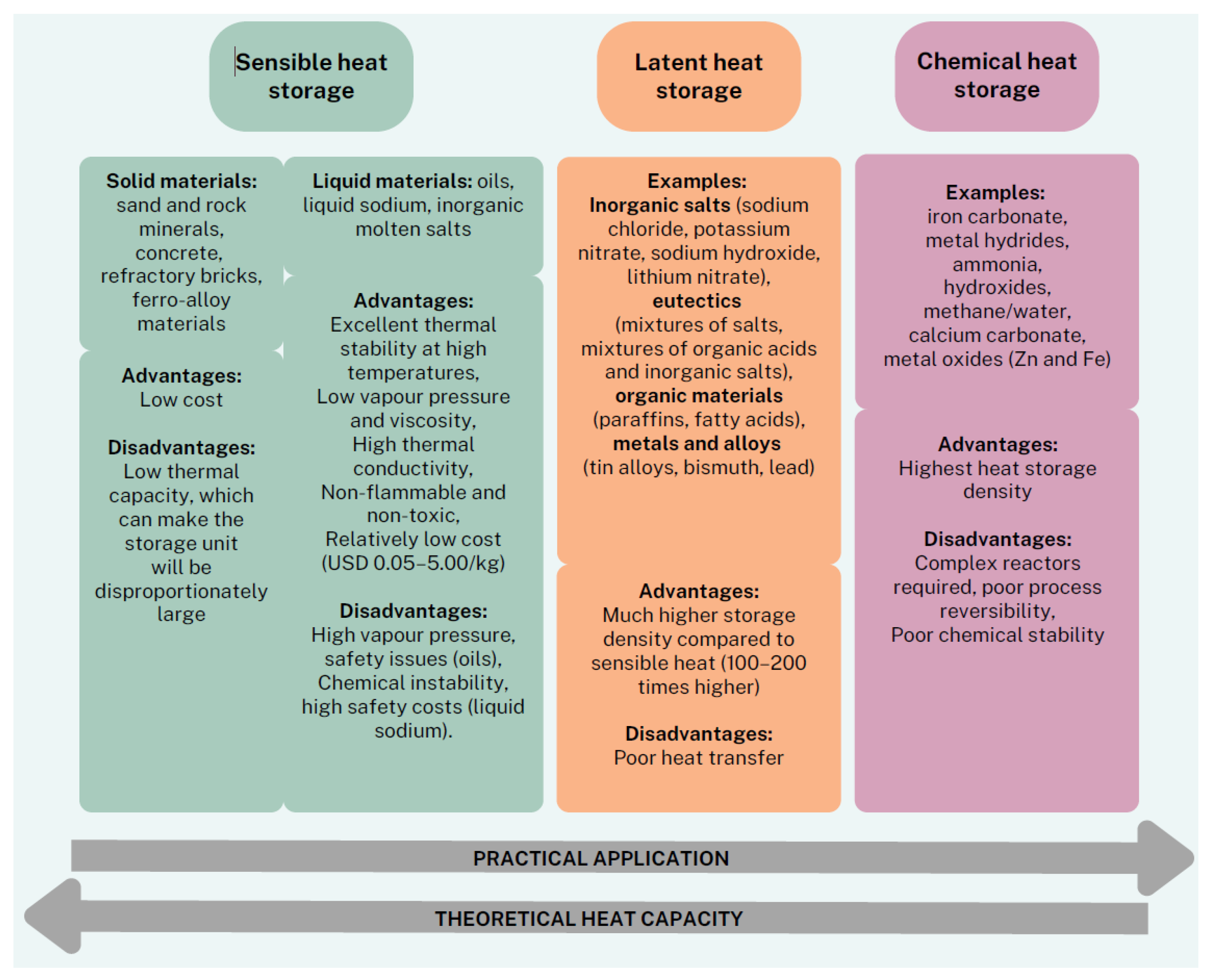
12], a classification of energy storage systems has been proposed, taking into account the advantages and disadvantages of each type (
Figure 1).
The most developed and widely available technology is sensible heat storage, which involves raising or lowering the temperature of materials that store heat as internal energy. The materials used can be in a liquid or solid state. Water is one of the most popular materials due to its low cost and high specific heat, but its use is limited to temperatures below 100 °C. Alternatively, liquid salts offer excellent thermal properties, higher stability, and the ability to store heat at higher temperatures. Unfortunately, their use is more complex and expensive, particularly due to safety issues, especially with oils or liquid sodium. Additionally, it has the lowest energy storage capacity, which significantly increases the size of the system. Latent heat storage, on the other hand, provides a higher storage capacity through phase change materials (PCMs), which store and release heat during phase transitions, such as solid to liquid, liquid to gas, or from one solid phase to another. The high phase change enthalpy makes the heat storage density in this technology much greater than in sensible heat storage. However, without proper improvements in heat transfer, the efficiency of latent storage may be limited due to poor heat transfer. The final type, chemical heat storage, offers the highest capacity among thermal energy storage technologies, as it is based on energy released or absorbed during chemical reactions. It uses organic or inorganic materials that can store large amounts of heat. Despite high efficiency, this technology is limited by the complexity of chemical reactors, the need to control reactions, reversibility issues, and the chemical stability of materials, which hinders its widespread application.
The paper [
13] compares three types of heat storage technologies—sensible, latent, and thermochemical—in terms of the volume of storage required to store the same amount of energy. The focus was on their energy efficiency, measured in megajoules per cubic metre (MJ/m
3), which illustrates the significant difference in energy density stored by the different technologies.
Another very important aspect of describing heat storage is considering the size of the storage systems. To store the same amount of sensible heat equal to 6480 MJ, a storage volume approximately seven times larger is required compared to thermochemical technology. Such a difference in storage sizes impacts the choice of technology depending on the available space and the requirements of the energy system.
Scientists from the Mineral and Energy Economy Research Institute of the Polish Academy of Sciences presented a comparison in their work [
14] in the form of a table (
Table 1) of different thermal energy storage technologies in terms of capacity, power, efficiency, storage duration, and costs.
Sensible heat storage systems are the cheapest option but offer low capacity and efficiency. Phase change storage systems provide higher efficiency and greater flexibility in storage duration, but they are more expensive. Thermochemical storage systems, on the other hand, have the highest capacity and efficiency, but their costs are the highest, making them the most suitable for shorter energy storage periods.
2.2. Heat Storage Materials and Methods for Improving Their Thermal Conductivity
Key factors for effective energy management in energy systems include the type of materials used for heat storage and innovative methods to improve their thermal conductivity, which enable more effective use of available energy sources.
In the publication by PhD Jerzy Chodura [
15], concerning modern methods of solar energy storage and utilization, the author addresses the issue of mismatch between the current availability of solar energy and the actual needs of the user. He points out numerous limitations of traditional systems, such as their large sizes, the limited thermal capacity of water as a storage medium, and the lack of ability to effectively utilize energy when the storage tanks are full while solar energy is still available.
Due to the limited capacity of water to store energy (about 60 kWh/m3), research has begun on materials with higher storage efficiency and new methods of heat storage. One of the solutions is phase change materials (PCMs), which can store a large amount of energy at significantly lower temperatures than water. The energy stored during a phase change, such as the melting of ice, is much greater than the energy needed to heat water to 80 °C.
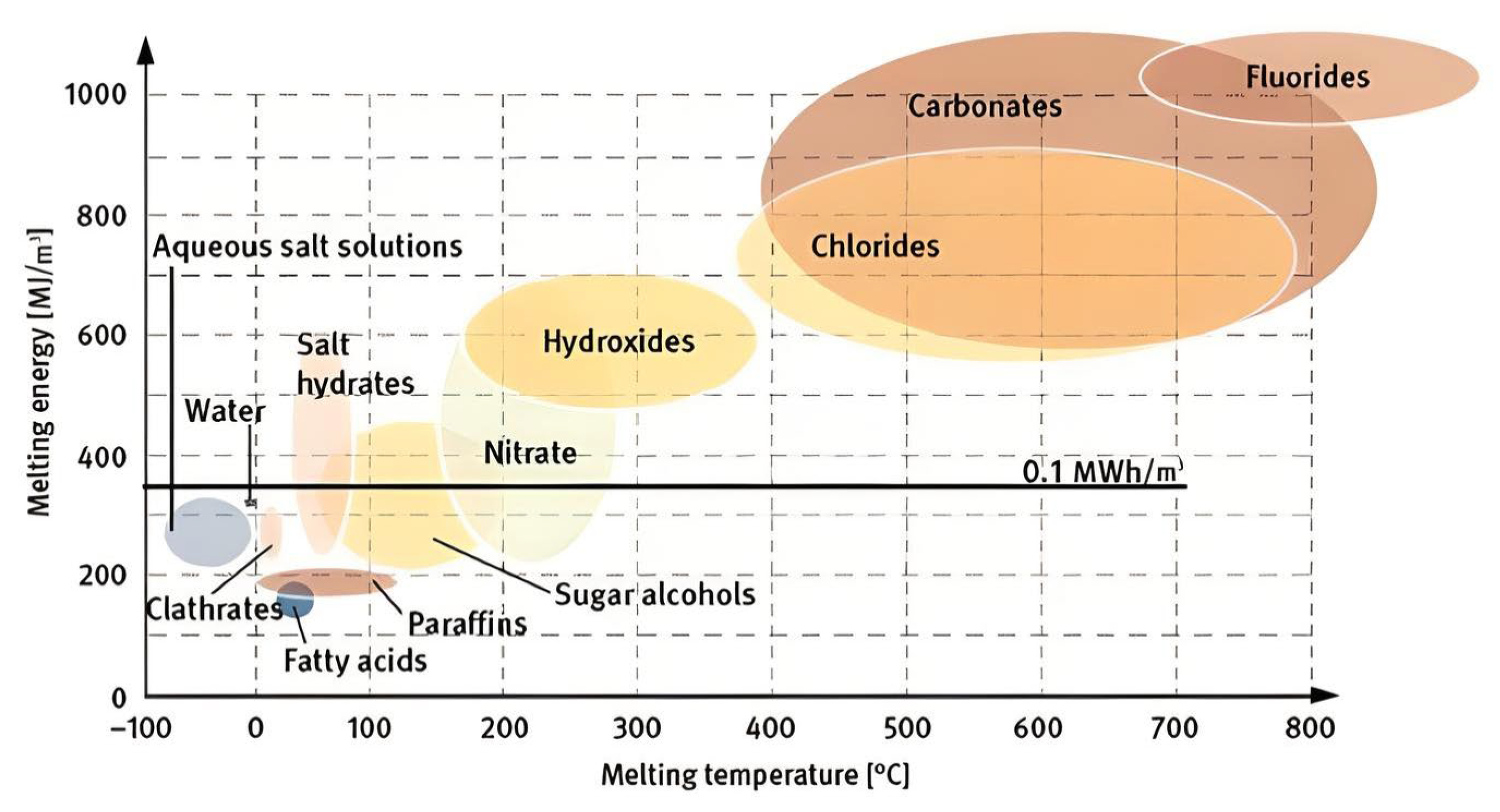
Phase change materials offer the ability to store heat over a wide temperature range, from below 0 °C to over 800 °C, making them useful in both heating and cooling systems. Due to this property, they can be used to store both heat and cold. In
Figure 2, included in publication [
16], the relationship between temperature and melting energy for various heat storage materials is presented. Groups of phase change materials are illustrated in the context of their thermal properties, further highlighting their diversity and application in effective energy management.
With such knowledge, it is possible to assess the potential applications of these materials in heat storage systems depending on the required temperature and energy parameters.
A key aspect of reducing the charging and discharging time of thermal energy storage systems is optimizing the thermal conductivity of the materials used in these systems. Higher thermal conductivity of materials allows for more efficient heat flow, which directly affects the speed of charging and discharging the energy storage systems. To enhance this process, the authors of the text [
17] decided to use materials with high thermal conductivity. In their research, they utilized elements such as plates, spheres, and metal powders. These inserts aimed to increase the efficiency of heat exchange in the storage systems. Although their application yielded positive results, the increase in thermal conductivity proved to be limited, ranging from 60% to 150%.
Although these materials contributed to improving the efficiency of the systems, the authors decided to explore other solutions in search of materials with even higher conductivity parameters. In this context, carbon materials were highlighted, which can achieve thermal conductivity levels of up to 470 W/(m·K). Due to their exceptional properties, these materials were tested for their application in thermal energy storage systems. The research showed that the use of carbon materials yielded significant results, leading to a twofold increase in heat transfer efficiency in energy storage tanks. Thanks to such innovations, it is possible to significantly accelerate the charging and discharging processes of the systems, improving their overall performance.
3. CFD
Numerical simulations, including CFD methods, play a key role in the analysis of many issues, such as solving mining aerology problems [
18,
19] or optimizing ventilation processes in large-scale halls [
20]. The technique is also widely used in improving the performance of refrigeration systems and thermal storage, enabling accurate modeling of complex thermodynamic processes. Thanks to advanced computational algorithms, it is possible to optimize the parameters of the systems, leading to increased energy efficiency and reduced operating costs. Theoretical research also allows the identification of innovative solutions that can significantly improve the use of renewable energy under different climatic conditions.
3.1. CFD Mathematical Models and Modelling Approaches: Advantages and Limitations
Among the popular CFD methods applied in the analysis of solar system efficiency is the
k −
ε model, widely used for its simplicity and relatively low computational requirements while maintaining adequate accuracy. Proposed by Chou in 1945 [
21], this semi-empirical model is based on transport equations for turbulence kinetic energy
k and its dissipation
ε. These equations describe the generation and dissipation of turbulence kinetic energy, allowing the simulation of turbulent flow behavior in various systems.
The
k −
ε model consists of two main equations:
where:
—constant parameters,
—dynamic viscosity [kg/(m∙s],
—empirical coefficient,
—density [kg/m3].
Turbulent viscosity is determined from the relation:
The constant parameters were determined empirically and are:
In this model, the representation of the Reynolds stress tensor is assumed in the form:
or in a simplified form for isochoric flows:
where
is the Kronecker delta.
Fluent solves the energy equation in fluid, in the following form:
where:
—effective conductivity (W/(m∙K)),
—diffusion flux (m/s2),
—flow velocity (m/s),
—density (kg/m3),
E—total energy (J),
—enthalpy (J),
—volumetric heat source (W/m3).
Heat transport in a solid is described by the equation:
where:
—thermal conductivity (W/(m∙K)),
—flow velocity (m/s),
—density (kg/m3),
—enthalpy (J),
—volumetric heat source (W/m3).
The k − ε model has been widely applied in CFD calculations for solar systems, where turbulence significantly impacts heat exchange efficiency. It is particularly useful in analyzing thermal stratification in thermal storage tanks, where accurately modeling temperature distribution and fluid dynamics is essential. This enables better understanding and optimization of heat flows and energy storage efficiency in solar systems, which is critical for improving the effectiveness of such setups.
In addition to the popular
k −
ε model, there are other turbulence models that can be valuable in analyzing solar systems, especially when higher precision and detail are required. For example, the
k − ω model is often used for simulating wall-bounded flows and situations where accuracy near surfaces is crucial. The transitional SST (shear stress transport) model combines the advantages of both the
k −
ε and
k − ω models, making it more suitable for analyzing complex flows, such as those found in thermal storage tanks [
22]. Another advanced approach is LES (large eddy simulation), which enables the direct modeling of large turbulent eddies, providing a detailed view of flow dynamics, though it requires substantial computational resources [
23]. The choice of model thus depends on the analysis requirements—simpler models like
k −
ε are used where general predictions are sufficient, while more advanced approaches are beneficial for in-depth analyses of complex systems, allowing for more precise predictions of solar system behavior.
Multiscale models combine calculations at the micro and macro levels, allowing for the simulation of phenomena at different spatial and temporal scales within a single, integrated model [
24]. This approach is particularly valuable in analyzing solar systems, where it is necessary to simultaneously account for detailed interactions at the molecular level (such as microscale heat exchange) and the broader dynamics of flow and energy exchange across the entire system.
In the context of solar energy systems with thermal storage, a multiscale approach can be used to model both thermal stratification processes and the dynamic flow of fluids within storage tanks [
25]. At the microscale level, detailed processes of heat exchange and micro-turbulence in the boundary layers of the fluid are modeled. Meanwhile, at the macro level, the overall flow dynamics and thermal energy changes across the entire system, including interactions between storage tanks, heat exchangers, and other components, are analyzed. This dual-scale modeling enables more accurate predictions of system behavior, such as temperature layering, which is crucial for optimizing heat losses.
Combining these two scales in one model allows for better optimization of parameters, such as the shape and size of storage tanks, the placement of baffles, and the optimization of fluid flow within the system. Multiscale models also allow for a more realistic consideration of external factors, such as changes in ambient temperature, which can affect system efficiency. Through this approach, engineers can design solar systems that not only make better use of solar energy but are also more resilient to varying operational conditions.
Various approaches to CFD simulation are used in the literature, each with their own strengths and weaknesses, depending on the simulation conditions and the expected results. This section identifies some key approaches, with a focus on their advantages and limitations. This analysis will help to understand which approaches are most effective in the context of studying solar and heat storage systems.
This approach involves averaging the Navier–Stokes equations over time, which allows turbulent flows to be modelled by separating the variables into mean and fluctuating components [
26,
27]. The strengths and weaknesses of RANS approach are aummarized in
Table 2.
- 2.
LES (Large Eddy Simulation)
This involves resolving large turbulence structures directly, while modelling smaller vortices, allowing more accurate analysis of complex flows [
28,
29]. A detailed comparison of the advantages and limitations of this approach can be found in
Table 3.
- 3.
DNS (Direct Numerical Simulation)
This relies on the direct solution of the full Navier–Stokes equations to capture all scales of turbulence without averages or approximate models [
30], with a summary of its key features presented in
Table 4.
- 4.
DES (Detached Eddy Simulation)
DES is a hybrid method that applies RANS to low-turbulence-flow areas and LES to high-turbulence regions, increasing modelling flexibility [
31]. A comprehensive overwiev of strenghts and weaknesses of this method is provided in
Table 5.
The analysis of turbulence modelling approaches provides valuable information about the strengths and weaknesses of different CFD methods. The selection of a suitable model depends on the specific project requirements and the characteristics of the solar and heat storage system under analysis. Comparison of the different approaches also provides valuable guidance for future research and practical engineering applications, which can contribute to the further development of solar technology.
The authors of the text [
32] created a numerical model of a solar-assisted heating, ventilation, and air-conditioning system for an educational building in a desert climate. The goal of this project was to predict the performance of the system, optimize control parameters, and achieve savings compared to the installation of photovoltaic panels. Simulations focused on analyzing thermodynamic changes in the system over time.
The mode of operation of the designed system varied according to the time of day and year, using solar energy to heat water and power an absorption chiller during the day and summer. At night and in winter, the system used stored heat or cooling, adjusting its operation to meet the building’s current heating and cooling needs.
TRNSYS software was used to develop the model, which allows the time-series simulation of thermodynamic interactions in various energy systems, including those based on solar energy [
33]. The model aimed to find the optimal control strategy that maximizes the use of solar energy for heating and cooling the building.
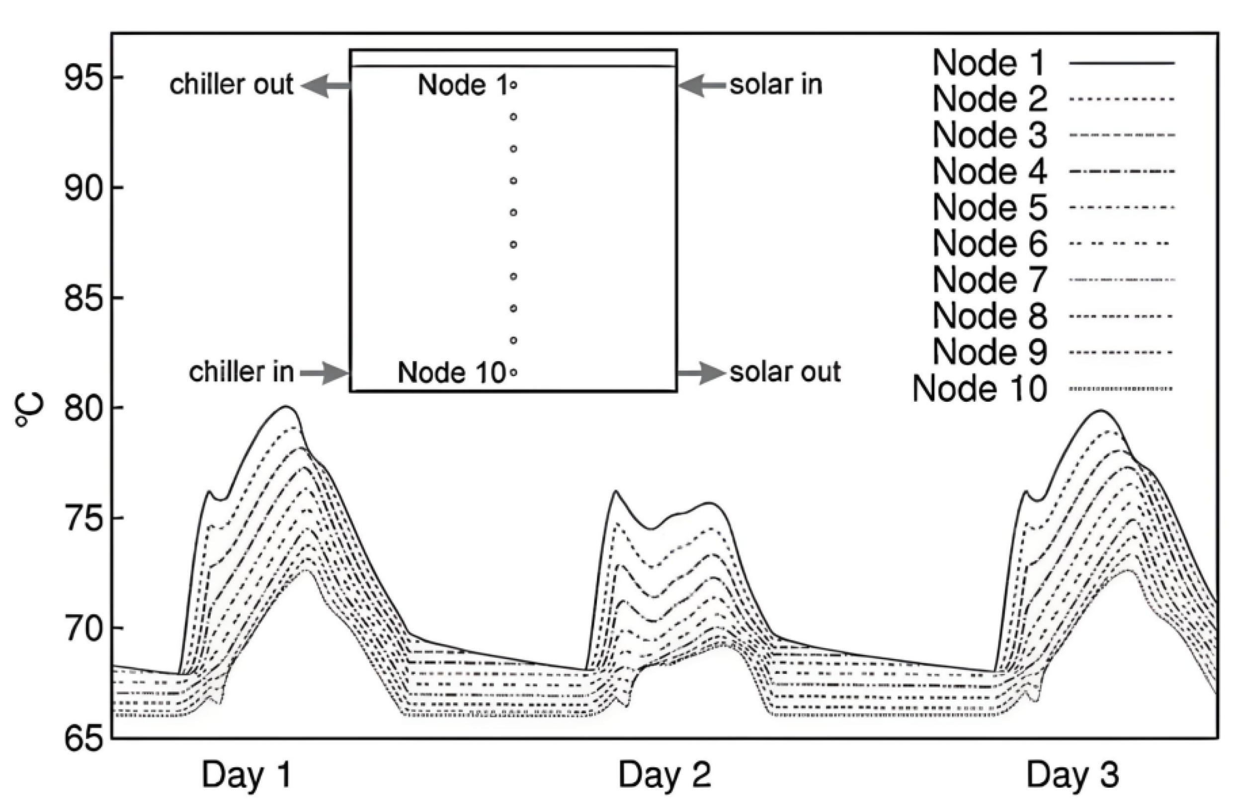
Simulations showed that the cooling system operated more efficiently at lower heating medium temperatures, which is beneficial for longer absorption chiller operation cycles. Supporting cooling with solar energy was able to reduce the total cooling energy demand by 33% to 43%. In addition, better results were obtained at lower operating temperatures for the solar panels. During the heating season, the solar system was able to cover more than 90% of the heating demand, provided appropriate energy-saving strategies were used. The solar collectors operated efficiently at the lowest possible discharge temperature, and during the transitional season, the building could operate without an external energy source, using excess heat to produce chilled water, which was stored for later.
Figure 3 shows a model of the tank that illustrates the linear temperature profile along its height.
The tank model did not allow any node to have a temperature higher than the node above it, as this could result in disruption of thermal stratification. In the event of such a situation, adiabatic mixing of the two nodes and equalization of temperatures occurred. The changing temperatures of the heating medium significantly affect the efficiency of the system and the absorption processes, which is crucial for optimizing the operation of thermal energy storage.
3.2. Using CFD to Analyze Performance of Solar Collectors
The use of numerical methods, in particular CFD analysis, has become a key tool in optimizing the performance of solar collectors. Thanks to these techniques, it is possible to study in detail the heat flow, temperature distribution, and other relevant parameters that affect the efficiency of collectors under different operating conditions. This subsection presents an overview of studies using computational fluid mechanics to analyze the performance of solar collectors, with a focus on the impact of absorber tube geometry and other key design parameters on system efficiency.
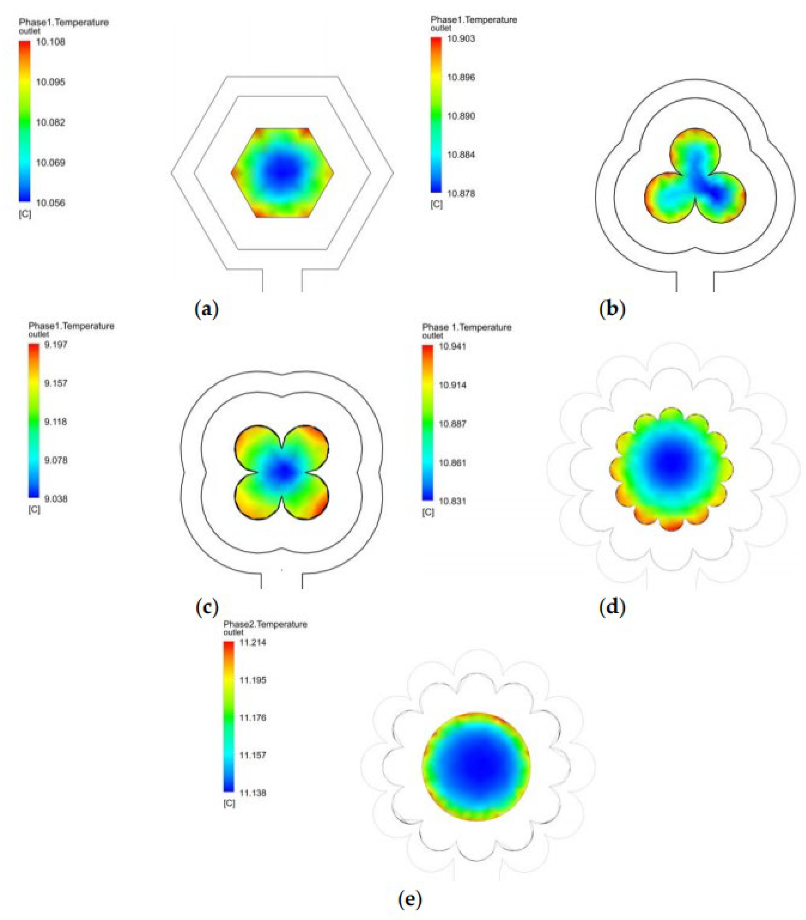
The article [
34] focuses on optimizing the performance of flat-plate solar collectors by examining the impact of various geometric configurations of the cross-section on heat transfer efficiency. The study analyzes different cross-sectional geometries, including innovative designs such as “three-leaf” and “four-leaf” shapes, aiming to demonstrate that changes in geometry can significantly affect the thermal performance of solar collectors, which are crucial for effective solar energy conversion in applications such as water heating and space heating. The analyzed absorber tube shapes are illustrated in
Figure 4.
The research systematically evaluates how different cross-sectional shapes influence flow dynamics and heat transfer rates within the collector. By comparing traditional circular geometries with more complex shapes, the authors aim to identify designs that maximize thermal efficiency.
CFD simulations were employed to model fluid flow phenomena and heat transfer, allowing for the visualization of temperature distributions, velocity fields, and pressure drops across various configurations. This facilitated an in-depth analysis of how structural changes impact overall performance. The effectiveness of each geometric configuration was assessed based on parameters such as outlet temperature and efficiency. The results indicated that specific designs led to noticeable increases in outlet temperatures, suggesting improved heat transfer capabilities compared to conventional solutions. Additionally, the CFD results were validated against experimental data from previous studies, ensuring the reliability of the findings. The research findings revealed that the use of innovative cross-sectional shapes significantly enhances the performance of solar collectors by increasing heat transfer efficiency. The best solution turned out to be an absorber shaped like a flower, which yielded the highest thermal efficiency results. Conclusions drawn from this study emphasize the potential for geometric optimization in designing more efficient solar thermal systems and highlight the important role of CFD as a tool for analyzing and advancing modern solar technologies.
A very similar scope of research was presented in the article [
35]. The authors conducted analyses of the impact of pipe shape (hydraulic diameters of 10 mm, 5.12 mm, and 6.16 mm were examined). The article compared the values of efficiency, speed, and pressure drops generated by different types of pipes. The studied cross-sections were shown in
Figure 3 of the described article. The best results were achieved by the collector with type one pipes installed, which had the largest hydraulic diameter.
The study [
36] discusses the use of computational fluid dynamics to analyze the performance of flat-plate solar collectors equipped with triangular absorber tubes. The primary objective of the study was to investigate how the geometry of the absorber tube affects heat transfer efficiency and the overall thermal performance of the solar collector.
The authors employed CFD simulations to model fluid flow and heat transfer characteristics in the configuration with a triangular tube compared to traditional circular tubes. Utilizing ANSYS Fluent software, they aimed to evaluate various operational scenarios, such as different temperature distributions and pressure drops, to understand how these factors influence the efficiency of the collector.
The results of the CFD analysis indicated that the design of the triangular absorber tube significantly improves thermal performance due to an increased surface area in contact with the absorber plate, leading to better heat absorption. The study revealed that the outlet temperature of the fluid was higher in the triangular configuration compared to other designs, indicating superior heat transfer capabilities. The authors concluded that optimizing the geometry of absorber tubes is crucial for maximizing the efficiency of flat-plate solar collectors. This research highlights the effectiveness of CFD as a powerful tool for analyzing and refining solar collector designs, ultimately contributing to more efficient utilization of solar energy in heating applications.
The research presented in the article [
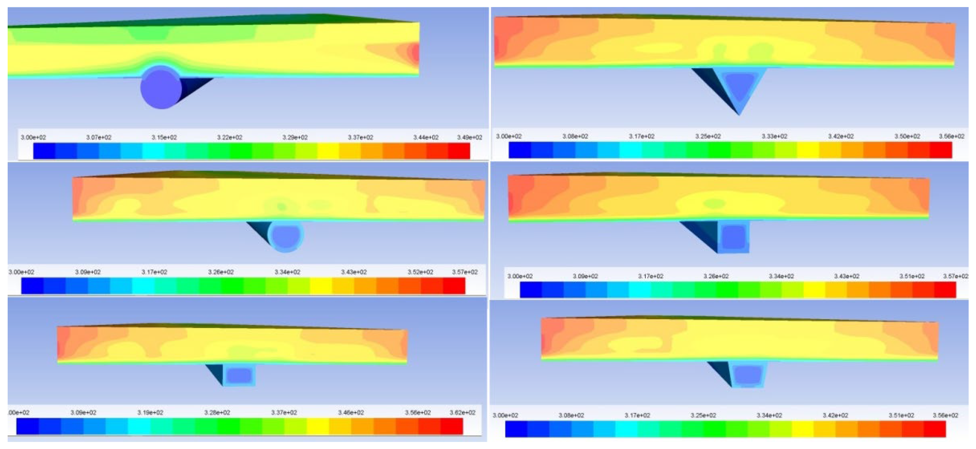
37] is concerned with enhancing the thermal performance of flat-plate solar collectors through the application of CFD. The primary objective of the study was to investigate how geometric modifications to the absorber tube can influence heat transfer efficiency within the solar collector system.
The authors utilized CFD simulations to analyze various design parameters of the collector, particularly geometric changes to the absorber tube, and their impact on fluid flow dynamics and heat transfer characteristics. ANSYS Fluent software was employed for modeling and assessing the performance of the collector under different operational conditions.
The results of the CFD analysis indicated that a circular cross-section absorber tube with a flattened contact surface with the absorber plate provided significantly better thermal performance compared to other configurations, as illustrated in
Figure 5.
The conclusions drawn from the study suggest that optimizing the geometric design of the absorber tube is crucial for increasing the thermal efficiency of flat-plate solar collectors. The research highlights the role of CFD as an effective tool for analyzing and optimizing solar collector designs, contributing to more efficient utilization of solar energy in heating systems.
The aim of the article [
38] was to utilize CFD to analyze and optimize the performance of solar collectors. The primary objective of the study was to identify key design parameters, such as collector geometry, fluid flow, and thermal properties of materials, that affect the efficiency of solar systems.
To create a detailed numerical model of the solar collector and analyze different operational scenarios, CFD simulations using ANSYS Fluent software were applied. The study compared five different header-riser collector inlet configurations, including two single (inlet and outlet with one pipe) and three double (both inlet and outlet with two pipes). A header-riser collector is a type of solar thermal collector in which the fluid flows through vertical tubes (risers), fed from a horizontal inlet (header), enabling efficient heat transfer from the absorbers to the working fluids.
The results showed that collector designs with uniform fluid flow through the ascending pipes (risers) were the most efficient, while low-flow configurations led to high surface temperatures and low thermal efficiency.
The research highlights the importance of using CFD to optimize the design of solar thermal collectors, indicating that appropriate selection of design parameters can significantly improve their thermal performance. The authors suggest that advanced modelling techniques, such as CFD, are a valuable tool in the pursuit of more efficient solar energy systems.
The study published in the paper [
39] focuses on the use of computational fluid dynamics (CFD) to improve the efficiency of flat-plate solar collectors. The main objective of the study was to conduct numerical simulations to analyze the heat transfer capacity of solar collectors for various applications, including domestic and industrial heating.
The author used ANSYS Workbench software to create a 3D model of the collector, taking into account elements such as the air inlet, corrugated absorption plate, glass cover, and stones. The model was used to simulate various operational scenarios to assess the impact of these elements on fluid flow and heat transfer in the collector. The analysis involved 4500 iterations, examining various parameters such as flow velocity in different directions, turbulent kinetic energy, and temperature and pressure variations at different points in the collector.
The results of the CFD simulations revealed that changes in the geometry of the absorption plate and improvements in the dynamics of the working fluid flow can significantly improve collector performance. The study confirmed that CFD is a valuable tool for modelling and predicting the performance of solar collectors, thus supporting the development of more efficient solar thermal systems.
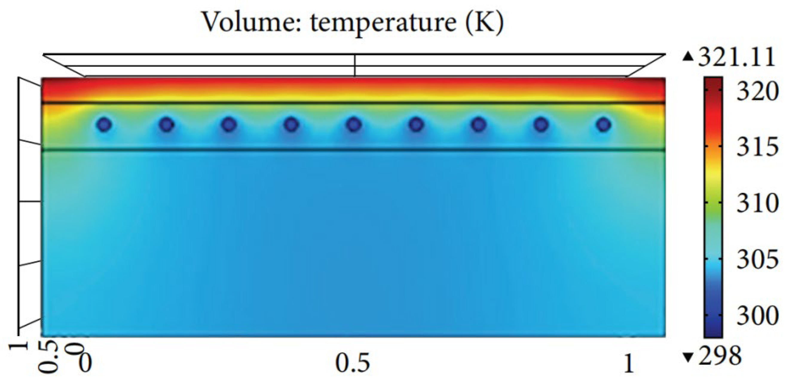
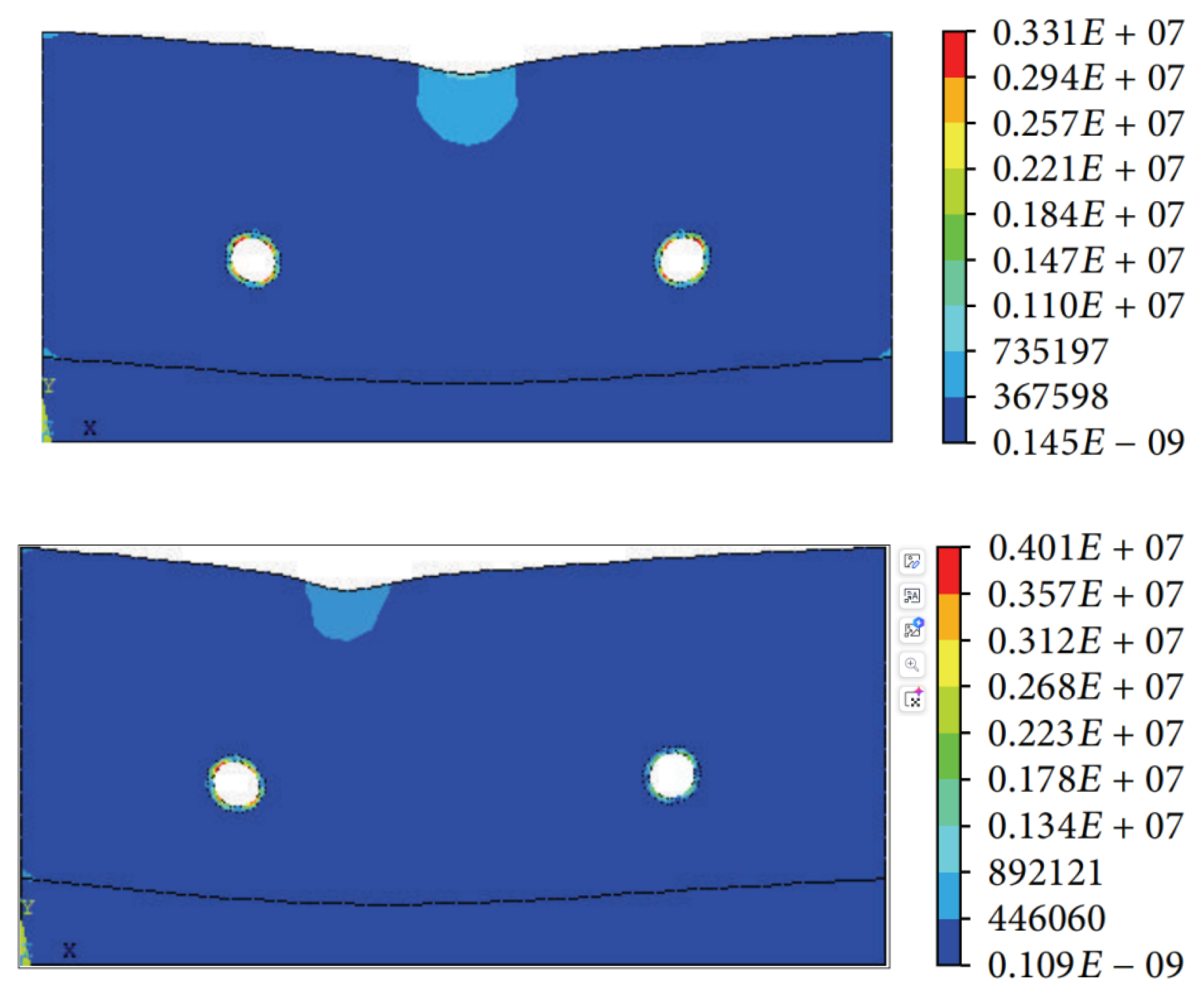
The study [
40] examines the application of the finite element method (FEM) to analyze the structural and thermal performance of asphalt solar collectors. The main objective of the study was to investigate how different structural parameters, such as pipe diameter, spacing, depth, and layout, affect the efficiency of asphalt solar collectors.
The authors conducted a comprehensive analysis to identify the optimal configurations that maximize heat absorption while ensuring structural stability under external loading conditions. Using FEM, they developed various models to simulate the thermal behavior of asphalt pavements subjected to solar radiation, which can reach temperatures of up to 70 °C due to their excellent heat absorption properties. The simulated temperature distribution in the asphalt layers is shown graphically in
Figure 6.
The analysis also considered the surface deformation of asphalt solar collectors, taking into account its impact on the structural integrity and thermal efficiency of the system. The authors paid attention not only to changes in surface shape due to thermal loads, which can affect the uniformity of heat distribution, but also to mechanical loads related to the process of asphalt heating and deformation under temperature and vehicle traffic loads (
Figure 7).
The simulation and results obtained indicated that the performance of asphalt solar collectors is significantly dependent on the layout and dimensions of the embedded pipes. The study showed that specific configurations can increase heat transfer efficiency while maintaining the structural integrity of the pavement. The authors concluded that the balance between thermal performance and structural stability is crucial to the design of effective asphalt solar collectors.
3.3. Using CFD to Simulate Thermal Stratification in Thermal Energy Storage Facilities
The growing interest in thermal energy storage technologies, especially in the context of concentrated solar power (CSP) systems, underscores the importance of effective management and optimization of these systems. This technology is gaining popularity due to its ability to integrate with thermal energy storage (TES) systems, which significantly improve the reliability and flexibility of the energy supply.
According to the authors of the review [
41], thermal storage is a key component in solar energy systems. Such thermal stores create layers of working fluid due to temperature differences, where the warmest particles rise to the top and cooler particles sink to the bottom. Such an arrangement lowers the return temperature of the medium to the solar collector, which increases the efficiency of the system. Research indicates that thermal stratification in thermal storage contributes to better utilization of stored energy and facilitates its further storage. The stratification reduces the rate at which liquids are mixed, which reduces the time it takes to charge the storage compared to storage that lacks distinct layers of liquids at different temperatures. A key factor affecting the effectiveness of stratification is the proportionality factor. According to Al-Marafi’s research, increasing the height-to-diameter ratio of a storage tank beyond a value of 4 brings no further benefit. Thermal stratification can also be improved by adding obstacles inside the storage, reducing the medium’s flow rate, and positioning the inlet and outlet closer to the tank’s edges. This placement helps maintain distinct temperature layers, as placing the inlet and outlet closer to the horizontal surfaces of the tank leads to a more pronounced thermal stratification, with less heat mixing between layers. In contrast, a larger distance between the spigots and the tank’s surfaces results in a blurred temperature gradient, suggesting increased mixing and potentially less efficient energy storage utilization [
42,
43].
In the context of the thermal stratification in question, low-cost thermal stores that use thermocline technology are an interesting alternative. A thermocline is a thin layer that separates liquids of different temperatures, thus preserving thermal stratification—a process in which temperature differences in different layers of liquids are maintained, without excessive mixing of hot and cold water. However, poorly designed systems can lead to intense mixing of hot and cold liquids, which adversely affects temperature stratification and ultimately reduces the thermal performance of the storage facility. The thickness of the thermocline determines the level of mixing of liquids of different temperatures—a thin and stable thermocline reduces heat transfer between hot and cold water during tank loading and unloading, improving stratification.
Factors negatively affecting stratification in TES systems [
44] primarily include natural convection with the environment, mixing due to the kinetic force of the fluid entering the tank, thermal diffusion and thermal conductivity in the water, and the interaction of walls, pipes, and other internal components. The shape factor of the tank (aspect ratio) also plays an important role. To improve the performance of thermal storage, special attention is paid to the type of heat transfer fluid (HTF) and the stratification process. Physical and geometrical parameters such as inlet velocity, supply temperature, tank aspect ratio, and the presence of stratification baffles that optimize temperature distribution and minimize mixing of layers with different temperatures are also important factors. CFD simulations provide a better understanding and optimization of thermal stratification processes, which increases the efficiency and reliability of TES systems in CSP technology.
In response to the growing demand for efficient heat storage materials, the authors of the text [
45] presented a novel approach. They used air as the working medium and used a porous bed as the charge inside the tank. CFD simulations using the
k −
ε model investigated the effect of heat conduction coefficient and capacity ratio on the charging efficiency of the thermal storage. Various values of Reynolds number between 8300 and 50,000, heat conduction coefficient (3.5–1062), and heat capacity of the cartridge (1483–7415) were analyzed. Two simulation scenarios included air turbulence in the porous structure and the thermal behavior of the system.
The distribution of turbulent kinetic energy in the inlet region of the tank reveals that hot air injection generates turbulent flow, particularly in the zone where the medium contacts the porous material. Analysis of the turbulence kinetic energy (KV) for different values of the Reynolds number shows that the KV rate increases significantly as it increases, penetrating deeper into the porous medium. The highest KV values occur near the air inlet (r = 0 to r = 0.25 m), and as the Re number increases, the area of clear flow is filled with high KV values.
The results showed that lower thermal conductivity values reduced heat loss, resulting in higher temperatures inside the tank after longer charging times. Heat capacity had a significant effect on transition moments, and higher Reynolds numbers, which imply stronger turbulence in the flow, reduced the benefit of using materials with low thermal conductivity. To compensate for this, it was necessary to increase the thermal conductivity of the materials.
Another paper [
46] described a two-dimensional numerical model for analyzing the process of energy storage and release in a thermocline of molten salt in a porous medium. The model of a cylindrical tank considered the process of heat storage by introducing high-temperature molten salt into the tank through an upper valve while removing lower-temperature salt through a valve at the bottom. The process of recovering the stored heat was reversed: cold molten salt flowed into the bottom of the tank, while hot salt flowed out the top.
Simulations showed that during storage charging, the thermocline layer stabilizes and grows over time, although the rate of growth decreases. The authors noted that although stable thermocline layers are formed in a tank with porous material, its heat storage efficiency is lower compared to tanks with pure molten salt. Ultimately, choosing materials with high heat capacity and optimizing the structure of porous fillers can improve the performance and cost-effectiveness of the storage.
Another important case, described in the article [
47], was the study of simultaneous charging and energy extraction from the thermal storage. The authors developed a model of a thermocline reservoir using molten salt as a medium and various filling materials: quartzite rock, slagstone, and alumina ceramics. The effects of charging and discharging intensities on the thickness of the thermocline layer and stored power were analyzed. The tank was subjected to stable charging or intermittent charging while discharging continuously.
Simulations showed that a tank filled with pure molten salt provided better thermal stratification compared to tanks with additional materials. The thickness of the thermocline layer increased with increasing flow rate, and the use of filler promoted uniform layer distribution along the radius of the tank. The greatest thickness of the thermocline was achieved with alumina ceramics. For the same flow rate, the temperature gradient was smaller for slagstone than for quartzite rock, suggesting that slagstone performs better as a heat storage material. In addition, continuous charging proved to be more efficient than intermittent charging at higher flow rates.
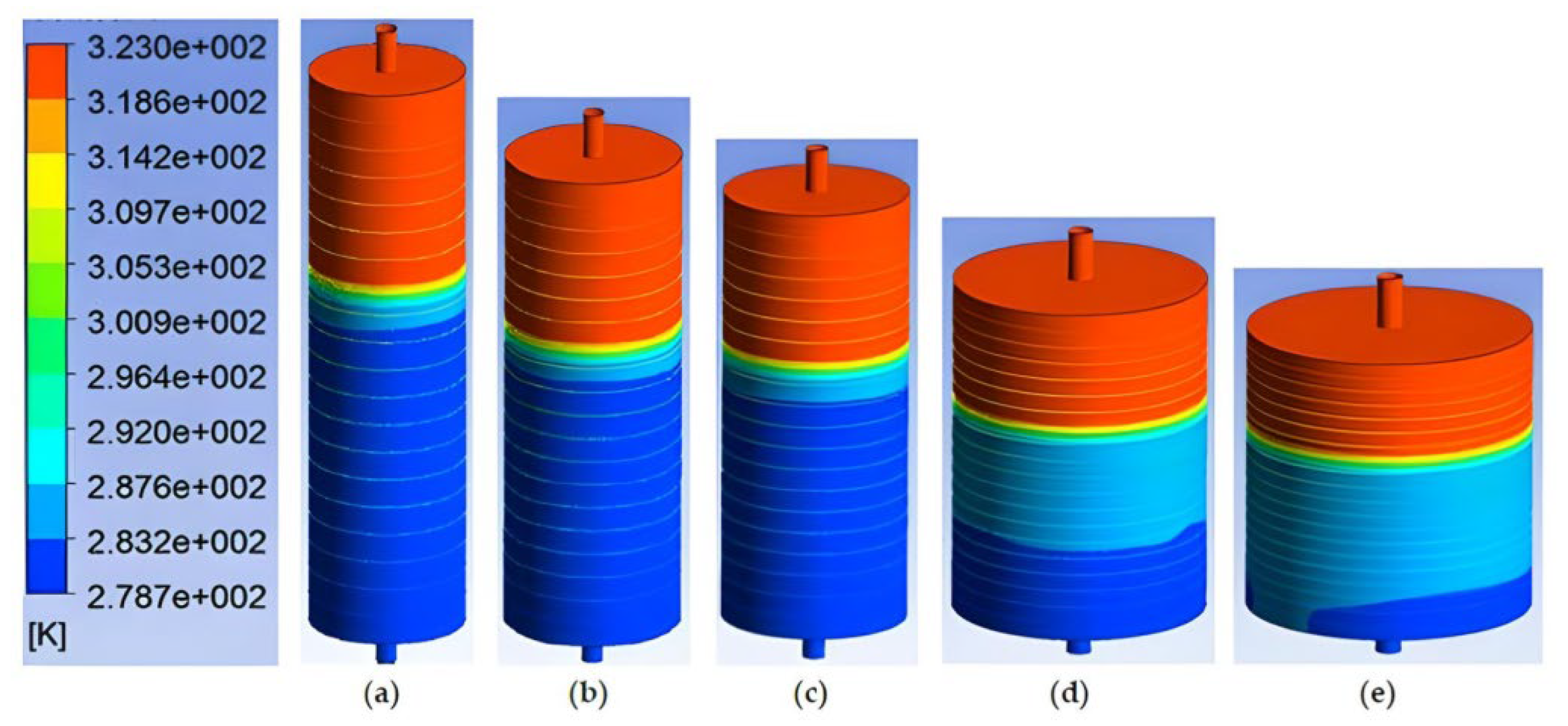
Much research has focused on the thermal processes occurring inside heat storage tanks. Researchers from the Department of Science and Engineering at Queensland University of Technology in Australia [
48] analyzed the theoretical performance of such tanks to identify key factors affecting their thermal efficiency in heating and cooling applications. Using CFD simulations, they studied five different fully insulated storage tank geometries with water as the heat transfer medium. The goal was to determine how the inlet velocity of the water, the ratio of tank dimensions, and the temperature difference between the tank water and the charging water affect water mixing and thermocline layer formation. The tanks differed in their aspect ratio, that is, the ratio of height to diameter (TES 1: AR = 3.8, TES 2: AR = 2.75, TES 3: AR = 2.38, TES 4: AR = 1.33, TES 5: AR = 1).
Figure 8 clearly shows the favorable effect of a high aspect ratio on the process of thermocline formation. In addition, it was noted that thermal stratification improved significantly as the temperature difference between the inlet medium and the initial temperature in the tank increased, along with lower inlet velocities. Observations showed that reducing the temperature difference between tank water and inlet water from 80 °C to 10 °C led to an increase in mixing by as much as 303%. Reducing the dimension ratio from 3.8 to 1.0 increased mixing by 143%. A similar trend was also observed when the inlet water velocity was increased. It is interesting to note that in the tank with the highest AR ratio (TES-1), it was possible to increase the inlet velocity without a clear effect on the shape of the thermocline after it was formed.
In article [
49], a research team from the University of Nantes in France studied the problem of uneven flow distribution in a single-tank solar salt heat storage system. Their proposal to solve this problem was to use stratification baffles with openings to improve the uniformity of temperature distribution in the tank. Using CFD, they conducted 2D simulations of the temperature distribution and fluid velocity during storage loading and unloading.
At the beginning of the study, they focused on the charging process and conducted three key CFD simulations for different configurations of tank geometry. The first simulation involved a tank without a top baffle (step −1), the second with two uniform baffles with openings (step 0), and the third involved an optimized baffle geometry whose distances and widths were adjusted based on an iterative optimization process. The optimization algorithm in MATLAB, implemented in six iterations (step 6), analyzed the data from the first two simulations and calculated changes in geometric parameters, which were then used to run new simulations in Ansys FLUENT. This yielded an optimized baffle configuration that provided the highest heat storage efficiency.
When analyzing the cyclic operation of the storage, including both loading and unloading, it was found that the geometry of the lower baffle has a significant impact on the efficiency of the unloading process. Therefore, using the optimized upper baffle from previous studies, an additional optimization of the lower baffle was carried out. The results showed that the optimized lower baffle improves the efficiency of both charging and discharging, leading to better flow management and less heat loss in the tank.
Various design parameters such as Reynolds number, aspect ratio, cone angle, number of holes in the baffle, and baffle porosity were also analyzed. It was found that optimizing the two baffles significantly improves the efficiency of heat charging and discharging in thermal reservoirs, and their appropriate combination yields the best results. A higher Reynolds number negatively affected temperature stratification, suggesting the need to control the fluid flow velocity at the inlet. In addition, a positive cone angle (θ = +15°) improved control of warm liquid flow compared to a negative angle (θ = −15°). The larger number of holes, higher aspect ratio, and lower porosity of the baffles improved stratification, leading to more efficient heat storage.
Another example of the use of computational fluid dynamics in studying the degree of thermal stratification of thermal storage tanks is published in [
50]. A team of researchers from Shandong University in China developed three models of three-dimensional cylindrical storage tanks that differ in the number of stratification surfaces with an opening. Numerical simulations were used to study the effects of the number of obstructions and fluid inlet velocity on thermal stratification. It turned out that increasing the number of obstacles significantly improved stratification in the tank. Specifically, at an initial velocity of 0.3 m/s, the tank with two obstacles was more effective in reducing the mixing of hot and cold water compared to the others. Thermocline thickness measurements were 0.87 m, 0.23 m, and 0.29 m for one, two, and three baffles, respectively. As the inlet velocity increased, mixing increased, especially in tanks with one barrier. Tank number 3 showed the least sensitivity to changes in velocity, and the thinnest thermocline layer was observed at 0.20–0.25 m/s.
A study by a team of researchers from the CanmetENERGY institute in Canada [
51] aimed to investigate the effects of design and operational parameters during charging on the flow, thermal stratification, and performance of the heat tank in solar energy systems. Two key design parameters were considered in the analysis: the aspect ratio (the ratio of the tank’s height to its diameter) and the position of the inlet and outlet ports. The operating parameters were mass flow rate, hot water temperature at the inlet, and initial water temperature. The study used CFD simulations of a three-dimensional insulated cylindrical tank with water as the medium.
The results showed that a high aspect ratio (AR = 3.5) provided the best thermal stratification. The higher the coefficient, the greater the temperature gradient between layers, which promoted better stratification. Decreasing the coefficient (AR = 2) led to worse stratification and lower temperatures. Changing the height of the tank at a constant diameter had no significant effect on stratification.
The location of the inlet/outlet port proved equally crucial. The best results were obtained with the inlet located near the top of the tank, where the thermal layer developed the fastest. Ports placed lower promoted more complex water mixing. The high hot water flow rate affected more intensive mixing, but stable thermal stratification was maintained. The optimal flow rate was 0.15 kg/s.
In the context of the inlet temperature, regardless of the difference between the initial temperature and the inlet water temperature, thermal stratification was stable, and water mixing was minimal.
An article by researchers from the Department of Engineering and Energy in India [
52] analyzed the performance of single-phase tank heat storage systems using different inlet configurations and working materials. They analyzed water and solar salt (a mixture of NaNO
3 and KNO
3) in different tank variants—both with and without a distributor. The study was based on CFD simulations, taking into account the location of the hot medium inlet and the presence of the distributor. The distributor in a heat storage system is designed to evenly distribute the hot medium in the tank, which translates into improved thermal stratification and increases the thermal efficiency of the system.
The results showed that the use of a distributor significantly improved thermal efficiency regardless of the working material. In the case of water, the distributor significantly reduced the thickness of the thermocline layer, which promoted better thermal stratification. In contrast, solar salt showed lower efficiency compared to water under the same conditions. The article emphasizes that the distributor improves thermal efficiency, especially in systems with water, while for systems with solar salt, further research is needed to improve the results.
Other researchers at the same institute in India investigated a thermal energy storage system using molten salts as the heat transfer medium and quartzite stones as the filler. In a paper [
53], they analyzed the effect of stone size on the performance of the thermal storage (TES) charging and discharging process using a three-dimensional model under laminar and turbulent flow conditions, verified by experimental results. The study included analysis of thermodynamic and geometric parameters, and the CFD–Taguchi method was used to optimize the system.
The results showed that charging and discharging efficiency decreased with time, and the optimal Reynolds number range (100–300) allowed better thermal stratification in the tank. Turbulent flow reduced system efficiency by 17.14% compared to laminar flow. Inlet temperature mainly affected heat loss through the outer walls, while smaller quartzite stones improved storage efficiency, although stones that were too fine or too large reduced porosity, which negatively affected charging and discharging processes.
The most significant parameters affecting performance were porosity and aspect ratio. The optimal settings, determined by the CFD–Taguchi method, were an aspect ratio of 0.25, Reynolds number of 10, porosity of 0.8, and fill size of 0.01 m.
3.4. Using CFD to Simulate Heat Loss in Thermal Energy Storage Systems
One of the main challenges in thermal energy storage systems negatively affecting their performance is heat loss. In order to reduce these losses and better understand the thermal processes occurring in thermal storage, computational fluid dynamics methods are widely used.
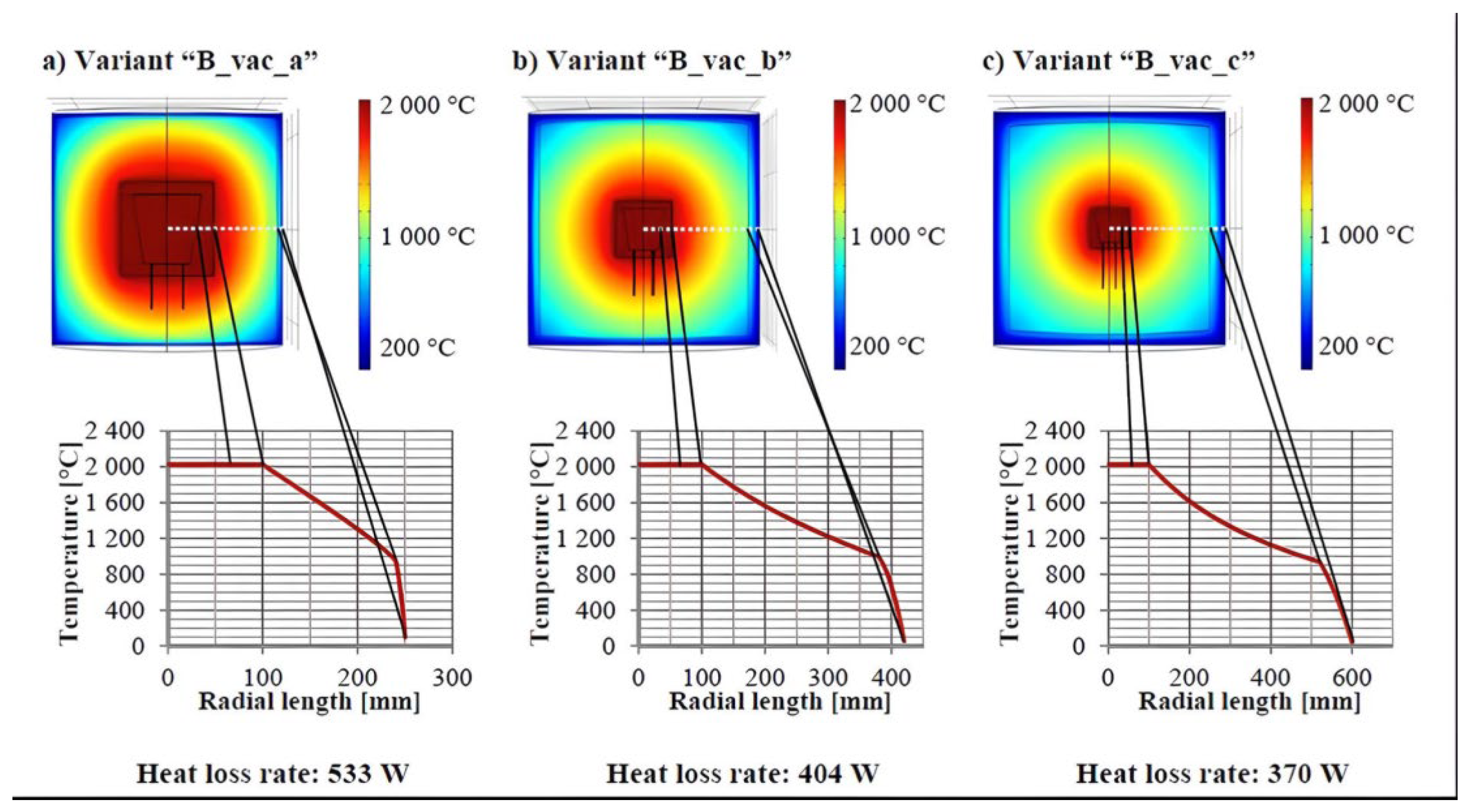
Researchers at the University of Stuttgart have focused their research on insulating materials for thermal energy stores operating at high temperatures of up to 2000 °C [
54]. Their research focuses on multilayer insulation, in which materials with better temperature stability are placed closer to the heat source.
Numerous simulations have been carried out to study heat loss and temperature propagation as a function of insulation materials, insulation layer thickness, and gaseous atmosphere. The thermal storage (TES) was modeled as a truncated cone with a height of 150 mm and diameters of 100 mm and 150 mm, maintaining a constant temperature of 2300 K.
The authors of the publication found that increasing insulation thickness can lead to an increase in heat loss. As a result, they suggest that the use of vacuum in insulation can significantly reduce thermal conductivity, which can almost halve the heat loss rate with less insulation thickness. They expressed the need for further research into vacuum materials and the costs associated with maintaining the vacuum, as well as alternative insulation techniques such as multilayer foil insulation.
Analysis of all tested variants (air, argon, and vacuum layer between insulation layers) showed that the heat loss coefficient decreases with increasing total insulation thickness (
Figure 9). However, increasing the thickness of the insulation leads to a decrease in effectiveness in reducing heat loss. This is due to the increasing external heat-transfer surface area with greater total insulation thickness. Heat loss reduction efficiency refers to how effectively an insulation reduces heat loss compared to its thickness. When insulation thickness increases, the amount of heat lost initially decreases noticeably. However, after a certain point, further increases in insulation thickness bring less and less benefit in reducing heat loss.
The article [
55] presents research on thermal energy storage systems in the context of insulation efficiency and heat loss in two different types of systems, rock cavern and aboveground, and focuses on comparing heat loss and heat transfer efficiency in these two systems. The study used a TES storage model using loosely stacked stones that store heat up to 685 °C. Numerical simulations were carried out, which included analysis of heat transfer in the stone packs and evaluation of ambient heat loss. The simulations were carried out over 10 years to determine the effects of various parameters on heat storage efficiency.
The results showed that cave TES systems have lower heat loss (69.2% lower) and better long-term stability compared to aboveground systems. In the first five days, there was no significant difference in the rate of heat loss between the two technologies (185.2–243.5 kW for cave TES and 188.0–241.3 kW for aboveground TES). However, in the last five days, the rate of heat loss in the cave system was significantly lower (162.48–110.23 kW) than in the aboveground system (190.3–242.0 kW).
Interestingly, the authors simulated the predicted temperature distribution on the rocks surrounding the cave storage after one year and 10 years of operation. Cave systems have shown less sensitivity to changes in insulation performance in long-term use, making them a more efficient solution compared to aboveground systems.
A Turkish scientist from Amasya University [
56] studied the effect of using glass wool insulation for a cylindrical tank (truncated cone insulation) and a rectangular tank (pyramid-shaped insulation) on improving thermal stratification in hot water tanks.
The effects of three parameters were analyzed: tank size ratio, diameter ratio, and thickness of bottom and top insulation. According to the study, the highest loss of exergy efficiency was only 0.034% for truncated cone insulation and 0.02% for truncated pyramid insulation, indicating minimal loss of exergy when using these geometries. In addition, the results showed that lowering the ratios of tank dimensions, bottom and top insulation diameters, and insulation thickness significantly improves thermal stratification, leading to a significant increase in the temperature difference between the bottom and top of the tank. The maximum increase in thermal stratification was recorded at certain values of these parameters, confirming the effectiveness of truncated cone and pyramid-shaped insulation in improving the efficiency of hot water tanks.
Computational fluid dynamics (CFD) methods are commonly used to analyze heat loss in thermal energy storage (TES) systems. These simulations allow detailed modeling of heat transfer processes, taking into account the influence of various parameters such as tank geometry, insulation materials, and ambient conditions. With CFD, it is possible to evaluate insulation efficiency, predict temperature distribution, and optimize thermal storage designs, minimizing energy losses. This allows better design of TES systems with higher efficiency and long-term thermal stability.
One of the main technical challenges in applying CFD to solar systems is the complexity of the geometry and configurations involved. Solar systems often include intricate geometries, such as tanks with stratification baffles, complex inlet and outlet arrangements, and heat exchangers with varying surface characteristics. Accurately modeling these configurations requires highly detailed computational meshes, which increases processing time and computational load. Additionally, the long timescales needed to simulate the diurnal and seasonal cycles of solar systems pose another challenge. Long-term simulations require efficient numerical methods to maintain accuracy while managing extensive computation times.
Furthermore, accurately modeling heat loss and thermal conduction in CFD simulations of solar systems is critical. External factors, such as ambient temperature variations, wind, and humidity, significantly affect heat loss from storage tanks and heat exchangers. Incorporating these boundary conditions in CFD adds complexity to the models. Another challenge is the selection and calibration of turbulence models, such as k − ε and k − ω and LES, to capture the effects of turbulence on heat transfer. Different turbulence models may yield varying results, making calibration essential to ensure reliable predictions.
Finally, scaling CFD results to real-world applications can be complex. Laboratory or numerical models may not fully capture the behavior of large-scale solar systems operating under variable weather conditions. This limitation underscores the importance of validation against experimental data, which can further enhance the accuracy and applicability of CFD analyses in energy efficiency optimization.
3.5. Current and Future Research Directions in CFD Applications
Table 6 presents the software and turbulence models used for numerical analyses in the articles described in this publication. It can be observed that most authors use ANSYS Fluent software, and when this information is provided, the most commonly applied turbulence model is
k −
ε. In a few cases, other turbulence models, such as
k − ω and Reynolds stress, have been employed. A less frequently used software for CFD analyses is COMSOL Multiphysics. Additionally, other software tools, such as CFD FloVENT, have been applied. MATLAB has been used as a supplementary tool. For numerical analyses of renewable energy systems, TRNSYS software is also utilized, primarily for long-term calculations necessary to determine, for example, potential savings. The analysis of the data in the table suggests that an important direction for future research could involve comparing results obtained using multiple turbulence models. Such comparisons would allow for a more comprehensive assessment of their impact on the accuracy of simulations and the reliability of the results.
Building on the analysis presented in the article and
Table 6, the following section outlines key areas where further research could advance the development of solar technologies and heat storage systems through the application of CFD.
In the context of the development of solar technologies and the efficiency of heat storage systems, there are many areas that require further research. This section outlines key topics that could form the foundation for future research works in the area of CFD applications.
Future research should focus on analyzing the efficiency and flow characteristics of reservoirs with different storage materials. This includes traditional materials, such as salt and stones, as well as innovative solutions, such as phase change materials (PCMs) or graphite composites, which can improve the thermal capacity and thermal conductivity of the system.
- 2.
Optimization of tank geometries
CFD can be used to study optimal tank shapes and layouts to help maintain heat layers and prevent excessive mixing. Analysis of the impact of internal structures, such as baffles or porous fillers, is key to the performance of storage systems.
- 3.
Advanced predictive models
The development of predictive models based on machine learning algorithms can improve the accuracy of predicting the performance of systems and allow parameters to be adjusted dynamically according to operational conditions.
- 4.
Analysis of the effects of long-term charging and discharging cycles
Cyclic thermal loading affects the performance of storage materials and tank geometry. Research can focus on operational optimization to reduce fatigue and limit energy losses during repeated loading and unloading cycles.
- 5.
Hybrid CFD models
The use of hybrid CFD models, such as DES or RANS-LES, can enable accurate mapping of flow in key areas of the reservoir with low computational requirements.
- 6.
Use of HPC technology
With the increasing availability of HPC technology, it will become possible to apply more advanced simulation methods, such as DNS, to larger systems. This will allow for more precise results when analyzing flow microstructure.
Consideration of the above research directions will identify key areas where CFD can support the development of efficient heat storage systems. Focusing on material innovation and advanced CFD models will contribute to the sustainable development of renewable technologies and better utilization of available energy resources.
4. Conclusions
This article discusses technologies related to renewable energy sources, with a particular focus on solar energy systems and thermal storage units. It presents a literature review on solar energy systems, and the design and performance of solar collectors and thermal storage units, which enable the optimization of these systems. The research conducted by the authors of the publication demonstrates that the appropriate use of thermal storage increases the efficiency of the systems, allowing for the accumulation of excess energy and its subsequent utilization.
The second part of the article focuses on the analysis of thermal processes occurring in thermal storage units and solar collectors, using computational fluid dynamics. CFD simulations allow for modeling the charging and discharging processes of the storage units, as well as the flow of the working medium. A key element in improving the efficiency of these systems is thermal stratification, which limits the mixing of heat and cold in the storage unit, thereby increasing its performance.
The review of articles provides valuable insight into the application of CFD methods in the analysis of thermal storage, highlighting their significant role in improving such systems. Most studies indicate the critical importance of optimizing tank geometry and flow parameters (such as the Reynolds number) in enhancing thermal storage efficiency. Stable thermocline layers can be achieved through the appropriate selection of filling materials (e.g., quartzite stones), which support the improvement of thermal energy storage (TES) system performance. Furthermore, various thermal storage technologies are presented, emphasizing the advantages and limitations of each. CFD analysis enables the refinement of tank geometry and the reduction of heat losses, which is crucial for increasing the efficiency of solar systems. The impact of the aspect ratio value on the formation of the thermocline was also noted. The higher its value, the more favorable its effect on the formation of the thermocline. Similarly, a higher temperature difference between the tank temperature and the inlet fluid temperature also positively influences the formation of the thermocline. Reducing the temperature difference between the inlet fluid and the fluid in the tank resulted in a 303% increase in mixing, while reducing the shape factor from 3.8 to 1.0 led to a 143% increase in mixing. Additionally, lower porosity of internal baffles contributes to effective heat capture in the tank, and a greater number of baffles also improves stratification within the tank. The placement of the TES storage is also significant. According to researchers’ findings, a TES system located in a cave exhibited nearly 70% lower heat losses and better long-term stability compared to aboveground tanks.
The article also presents numerical models used in CFD and their application in multiscale modeling, where simulations capture both microscale heat exchange and macroscale system flow dynamics. This multiscale approach, while requiring high computational power, provides a more comprehensive understanding of complex solar energy systems and allows for precise system optimization.
Research indicates the need for further development of thermal storage technologies and the materials used in them, which will enable the future estimation of potential costs for building actual solar systems that utilize solar energy. The use of numerical simulations for these purposes will contribute to better energy management in the context of global climate-related challenges.


 ,
, 
