Abstract
Many investigators have investigated flat-plate solar collector absorber plates based on one-dimensional heat flows. However, the shape of the absorber plate may always create a two-dimensional temperature distribution if it has a thin thickness. Hence, an analysis of the two-dimensional heat flow in absorber plates is always required. The current paper determines a closed-form solution for the energy equation to establish a two-dimensional energy flow for an absorber plate by considering a nonlinear temperature variation at the plate–tube section. The separation of the established variable method solves the energy equation. The same energy equation was also solved numerically using the finite difference method for validation purposes. It emphasizes demonstrating that the analytical and numerical results match closely with each other. Finally, this work concludes by developing an analytical model for the practicable thermal analysis of absorber plates in solar collectors, providing error-free implementation results.
1. Introduction
Environmental concerns have limited the use of fossil fuel reserves, and the increases in energy demand and rising costs of conventional energy generation have become major issues in our current climate. To help overcome these problematic aspects, renewable energy has experienced rapid growth in recent years, stepping up to address the looming energy crisis. One such renewable energy source is solar energy, which offers significant advantages due to its eco-friendliness and virtually infinite supply [1]. Solar collectors can obtain thermal energy from solar radiation. Solar flat-plate collectors (SFPCs) convert solar radiation to usable energy through various converting devices. This heating device is more effective than other solar collectors due to its simple structure and low running costs [2,3]. SFPCs are primarily employed in low- and medium-temperature systems, from household hot water and space heating to industrial drying, preheating and other engineering applications. They reduce carbon footprints, promote energy independence and mitigate the environmental impacts of conventional energy sources. Low convective heat transfer and thermal efficiency are the major problems with FSPCs [4]. Among their components, the absorber plate plays a pivotal role by absorbing solar energy and transferring it to the fluid in the tubes. This plate can be welded to or integrated with the fluid-carrying tubes, facilitating efficient heat transfer. As a result, the overall performance depends principally on the absorber plate’s effectiveness in capturing and transferring solar energy [5]. Hence, researchers focus on improving the collector efficiency. For this, an investigation of two leading research directions, namely heat transfer and optimization of the structure, is required.
In recent years, research has been conducted to analyze FPSCs in order to increase their efficiency and performance. The published work includes several theoretical, analytical, numerical and experimental analyses on finding innovative solutions for collector heat transfer, lowering heat losses and enhancing heat exchange between plates and collector fluid. Hottel and Woertz first analyzed solar collectors with a flat plate in 1942 [6]. Their study assumed a one-dimensional heat flow, constant thermal conductivity, and uniform overall loss coefficient. Later, Hottel and Whillier (1958) [7] and Bliss (1959) [8] independently presented a thermal model to determine usable energy absorbed by the absorber plate from solar irradiation, taking into account a constant heat loss coefficient. A complete work analyzing the absorber plates of a uniform cross-section was studied by Duffie and Beckman (1991) [9]. The design perspective requires investigating different shapes to enhance thermal performance based on the ease of manufacturing absorber plates (Kundu, 2002, 2007, 2008 [10,11,12]; Hollands and Stedman, 1992 [13]; Kundu et al., 2010 [14]). Because of its straightforward construction, a uniform-thickness plate is widely utilized (Kundu et al., 2010) [14]. Nayak and Amer (2000) [15] used theoretical and experimental determination to critically assess the dynamic test protocols of flat-plate collectors. Several researchers have utilized artificial neural networks, soft computing, and machine learning methods to forecast the performance characteristics of flat-plate collectors [16,17,18,19].
Further efforts to improve FPSC efficiency involve the application of polymers, mini-channels, phase-change materials (PCMs) and augmentation devices, viz. several categories of inserts and reflectors [20,21,22,23,24]. Zheng et al. [25] proposed a new concept for improving the performance of FPSCs by considering silica aerogel in the cover and transparent insulation materials. The idea for a micro-channeled stainless steel solar collector is the primary innovation presented in [26]. Numerical analysis and experimental investigations revealed that enlarging the micro-channel width and raising the corrugations’ height enhanced the collector’s thermal performance.
The working fluid of FPSCs has substantially impacted their thermal performance. Recently, attempts have also been made to investigate the applications of using nanofluids in solar energy conversion systems. FPSCs include numerical simulations and experiments where the usage of nanofluids is a crucial area of research. Modern techniques that use nanoparticles and nanofluids have increased the efficiency of solar collectors [27,28,29,30,31]. The direct absorption of incoming solar radiation by nanofluids containing nanoparticles makes them more thermally efficient than water. The thermal efficiency of nanofluids surpasses that of water when nanoparticles directly absorb incoming solar radiation [32,33]. Kundu and Lee (2012) [34] analyzed Fourier and non-Fourier heat transport in a flat-plate solar collector’s absorber plate using the separation of variables method. Employing energy and exergy analyses, a few researchers have also constructed analytical models to estimate collectors’ performances [35,36,37].
All the above analyses used a one-dimensional heat conduction equation. A two-dimensional temperature distribution in the absorber plate of the collector is satisfied, so a two-dimensional analysis is needed for a more accurate evaluation of its performance. Consequently, numerous studies have been conducted using a two-dimensional energy flow in absorber plates with different boundary conditions. Rao et al. (1977) [38] proposed a two-dimensional model to transport heat in absorber plates to estimate collector fluid temperature. Considering that there is no heat transfer at collectors’ upper and lower edges, Lund (1986) [39] developed a two-dimensional model for transferring heat in flat-plate solar collectors. His analytical solution was created while considered the perturbation series. Lund’s two-dimensional model was modified by Nag et al. (1989) [40], adopting convection boundary conditions at the upper and lower edges of the absorber plate. A finite element method determined the isotherms that deviate from a one-dimensional pattern to show a two-dimensional heat flow in a plate. Kazeminejad (2002) [41] analyzed one- and two-dimensional heat flows in a solar collector through a finite volume method. Nevertheless, three-dimensional (3D) models have also been established to scrutinize solar collectors’ heat transfer. Using a 3D model, Cerón et al. [42] forecasted the collector performance. Their study highlighted the Reynolds-averaged Navier–Stokes (RANS) turbulence model under a steady-state situation. Many 3D models were investigated based on computational fluid dynamics (CFD) that deal with stable states [43,44].
In all of the published works on two-dimensional heat conduction problems, conductive and convective boundary conditions were considered, with the temperature at the junction of the plate and fluid-carrying tube being constant. Since the collector fluid temperature in tubes increases from the inlet to the exit at the plate–tube junction, a variable temperature condition is appropriate. Due to this variation, the energy equation’s boundary condition becomes nonlinear. To the authors’ knowledge, this is the first time this temperature variation has been considered in this work. Hence, the present work analytically investigates heat transfer effects on two-dimensional heat transport in an absorber flat-plate solar collector. The product method was employed to estimate the temperature distribution for the above situation. The correctness of the present analytical model was checked with the results obtained by a finite difference method, and an accurate match was found.
2. Mathematical Model
The asymmetric sector is used for the thermal analysis of an absorber plate between two fluid-carrying tubes instead of the whole plate [11]. The geometry of the arrangement is depicted in Figure 1, where W, L and t are the half-center distance of the tube, the tube length and the plate thickness, respectively. The rate of mass flow through a single tube is m. The solar insolation S falls on the plate, and energy losses occur from the plate. As the collector plate is made of thin material, the ratio between the plate’s volume and area is always lower. Hence, neglecting the heat conduction in thickness direction, the flat-plate collector can be considered as a two-dimensional heat conduction problem (x-and y-directions, as mentioned in Figure 1).
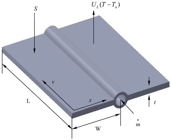
Figure 1.
A view of a flat-plate collector with a symmetric sector for thermal analysis.
This study on flat-plate collectors has made the following assumptions:
- Heat transfer in absorber plates satisfies two-dimensional flow under a steady state.
- For simplicity, the analysis omits the transparent covers.
- The solar insolation distributes uniformly over the plate and remains unchanged.
- The plate material’s thermal conductivity is invariable.
- There is no change in the surrounding temperature and overall loss coefficient.
- At the plate and tube junction, the plate temperature varies nonlinearly as a quadratic function.
2.1. Analytical Methodology
An energy balance on an infinitesimally small control volume in the absorber plate with the above assumptions provides the following differential equation:
where k is the absorber plate thermal conductivity, UL is the coefficient for losses from the plate and S is a flux absorbed from solar radiation and is an instantaneous value. For the low-temperature variation, the thermo-physical properties are assumed to be invariant. The following dimensionless parameters taken in the analysis are defined as,
Equation (1) can be written by combining Equation (2) to express a normalized governing equation as
As the plate temperature distribution is assumed to be two-dimensional, the fluid flows in the tube, which is in the y-direction, and the plate width is in the x-direction. Hence, the absorber plate is exposed to the surroundings and the conductive–convective boundary condition can be considered at y = 0 and y = L. The highest plate temperature in the middle between two tubes is due to a symmetric module; hence, no net heat transfer occurs across the section. In actual situations, the plate’s temperature at the tube junction varies nonlinearly. Therefore, the temperature at this section can be expressed as a function of y and a regression analysis can find its coefficients. Mathematically, the normalized boundary conditions for the absorber plate to determine the thermal response are as follows:
where
Here, A, B, and C are constants whose actual values can be found by a regression analysis. The method of separation of variables [45,46] can be adopted to solve Equation (3). This analytical method describes the steps with the following variables:
From Equations (3) and (6), one can obtain the following second-order differential equations:
and
The dependent variable is obtained by solving Equation (7) with the modified boundary conditions from Equations (4a) and (4b) as
where
and
The variable in Equation (8) is then separated by the product rule:
Equations (8) and (10) yield the following equations.
and
Solving Equation (11) with the modified boundary conditions obtained from Equations (4c) and (4d) gives an Eigen condition of
Equation (13) is a transcendental equation which can be solved by the Newton–Rapson iterative method to obtain the value of Eigen values . Equation (12) is solved with the modified boundary conditions obtained from Equations (4a) and (4b), and combining Equation (10) gives
where is a constant, and its value can be determined by the orthogonality condition from the Fourier series with the nonhomogeneous boundary condition (4b) as
where
Combining Equations (9), (9a), (9b), (14) and (15) results in the final expression for the normalized temperature distribution being
2.2. Design Parameters
The following formulae can be used to determine the flat-plate collector performance parameters [9]:
2.3. Numerical Analysis
A finite difference method is established in this study to solve Equation (3) subject to the boundary conditions expressed in Equations (9a) and (9d). Taylor’s series central difference scheme discretizes this normalized governing equation and boundary conditions with a second-order accuracy [47]. Then, the Gauss–Seidel iteration method is employed to solve these simultaneous algebraic equations to obtain the temperature at the lattice points. The grid-independent test was performed by choosing lattice points in the length and width direction. The optimum grid size (30 × 10) was determined to obtain the temperature, which will not be affected irrespective of increasing grid size. The final results are obtained after satisfying the desired accuracy level of 10−6.
3. Results and Discussion
This work’s primary goal is to analytically determine an absorber plate’s thermal performance for two-dimensional heat transfer in the plate and a unique temperature variation at the plate–tube junction. As an analytical tool, the separation of variables method is employed. A numerical approach based on the finite difference method is also used to determine the temperature to validate the present analysis. The input data for the simulations from which all of the results were obtained are tabulated in Table 1, considering water as the circulating fluid. In the aforementioned two-dimensional study, results were acquired by in-house FORTRAN programming based on these geometric parameters and the physical characteristics of the flat-plate collector.

Table 1.
The value of design parameters taken.
Based on analytical and numerical results, Figure 2 is drawn for the variation in non-dimensional temperature along the X-direction in an absorber plate. The temperature at the middle point surface (i.e., Y = 0.5) and the temperature at the unit step length surface (i.e., Y = 1) are shown in Figure 2a and Figure 2b, respectively. It is seen from the figures that the analytical and numerical results are in good accordance, which validates the accuracy of the analytical and numerical methods of the present paper.
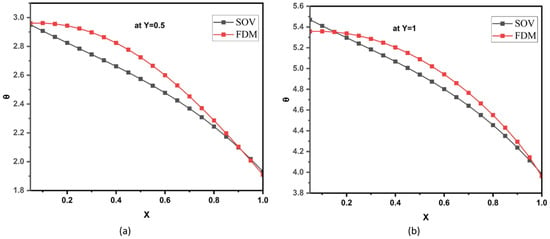
Figure 2.
Non-dimensional temperature distribution of the absorber plate along X-direction: (a) Y = 0.5 and (b) Y = 1.
Figure 3 depicts a normalized temperature distribution along the Y-direction in an absorber plate at X = 0.5 in Figure 3a and at X = 1 in Figure 3b according to analytical and numerical results. The figures also show that the analytical and numerical results are in excellent agreement, which indicates the correctness of the analytical results determined from the present work.
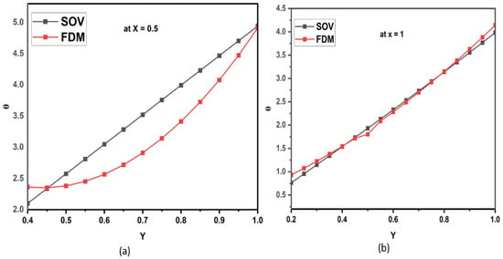
Figure 3.
Non-dimensional temperature distribution in the absorber plate along flow direction (Y): (a) X = 0.5 and (b) X = 1.
The isotherms are the most effective approach to illustrating the two-dimensional temperature distribution of the absorber plate. Figure 4 depicts the isotherm patterns across the absorber plate. There is a two-dimensional temperature variation in the heat transfer module section, as displayed in this figure.
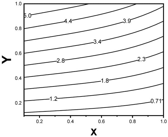
Figure 4.
Contour plot for temperature distribution over the test module.
The influence of varying the mass flow rate on the absorbing plate’s outlet temperature is depicted in Figure 5 for dissimilar fluid inlet temperatures. It can be observed that, as the mass flow rate increases, the outlet temperature declines. Also, we can see that, as the inlet temperature rises, the outlet temperature also amplifies. Raising the inlet temperature lowers the rate at which heat is transferred from the plate to the fluid, increasing the plate’s outlet temperature (as stated elsewhere), and raising the fluid inlet temperature results in a decrease in the fluid-absorbing plate temperature differential, which raises the absorber plate’s outlet temperature.
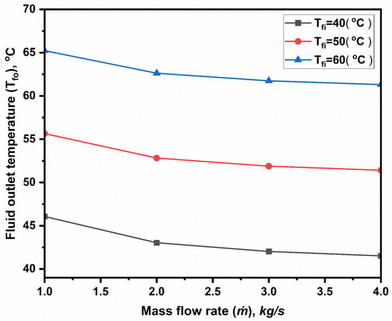
Figure 5.
Variations in the fluid output temperature with mass flow rate.
Figure 6 highlights the link between the exit temperature and the tube distance. How the distance between the pipes affects the temperature at the exit is addressed. It can be seen that, as distances rise, the fluid outlet temperature drops because of an increase in resistance to heat flow. Furthermore, the outlet temperature drops as the mass flow rate increases. The temperature has fallen because the fluid particles have less heat to carry.
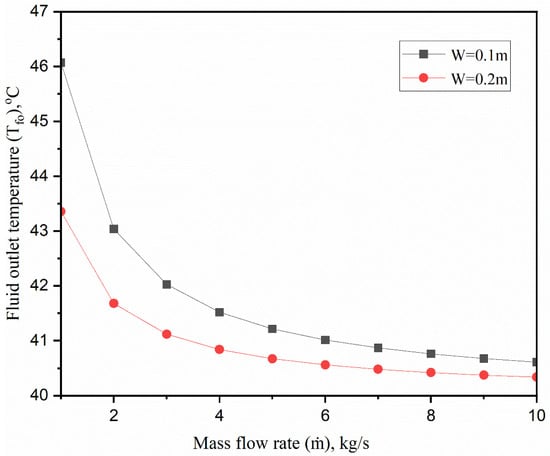
Figure 6.
Fluid outlet temperature as a function of the spacing between fluid-carrying tubes.
Figure 7 explains the effect of variations in the spacing between tubes that convey the efficiency of solar collectors. Interestingly, efficiency falls off as the tube length grows. Efficiency declines in an inverse relationship with the tubes’ separation. The relationship between this and the output temperature reduction seen in Figure 6 is clear. The outlet temperature drops with the increasing tube distance, which lowers the fluid’s heat transfer rate. As a result of decreased heat transfer, efficiency decreases.
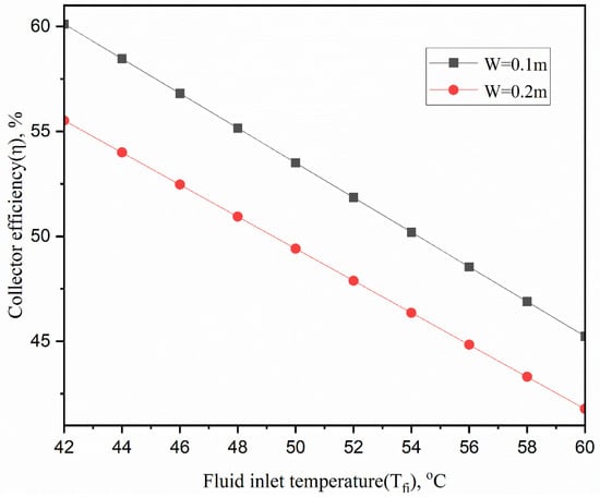
Figure 7.
Effect of the distance between the two collector tubes on the collector efficiency.
Figure 8 depicts the variation in collector efficiency with fluid inlet temperature for different mass flow rates. It shows that the efficiency increases as mass flow rates increase, which could be explained by increasing the mass flow rate. The fluid’s convective heat transfer coefficient rises, accelerating the heat transfer rate. Moreover, a rise in the mass flow rate will lower the mean temperature of the plate and lessen the heat loss to the environment. It also shows that collector efficiency falls for every flow rate as the fluid inlet temperature rises. This decreasing trend holds true for all flow rates and suggests that higher input temperatures diminish the system’s capacity to transform absorbed energy into usable heat outputs. This knowledge directs solar collector system optimization, allowing engineers to maximize efficiency and reduce energy loss.
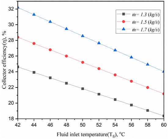
Figure 8.
Effect of mass flow rate on efficiency.
The effect of the absorbing plate’s thermal conductivity on efficiency is investigated in Figure 9. According to the figure, efficiency increases by 2% as heat conductivity increases. Nevertheless, materials with lower thermal conductivity, such as aluminum rather than copper, can be used without losing performance, as this gain in conductivity does not significantly improve efficiency. We could drastically cut the collector’s production expenses with this replacement. The linear nature of the efficiency decline also suggests a controllable effect on performance as inlet temperatures vary and supports accurate modeling of system performance under various operating situations.
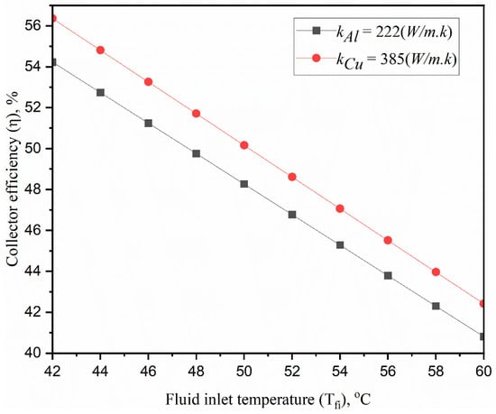
Figure 9.
Impact of absorbing plate conductivity variations on collector efficiency.
The results for the axial fluid temperature fluctuation are typical observations. Figure 10 depicts the fluid temperature distribution along the tube length for different mass flow rates at a given inlet temperature. The exit temperature rises with the increasing tube length, indicating that the fluid acquires more thermal energy as it moves farther inside the collection. Lower mass flow rates result in greater exit temperatures at any tube length. There is a nonlinear increase in output temperature with collecting tube length. This suggests heat transfer efficiency may change as the fluid progresses along the tube. A lower flow rate could be used to better optimize the outlet temperature, particularly for applications that call for higher fluid temperatures. The temperature increase’s nonlinearity indicates that it satisfies the boundary condition of the problem.
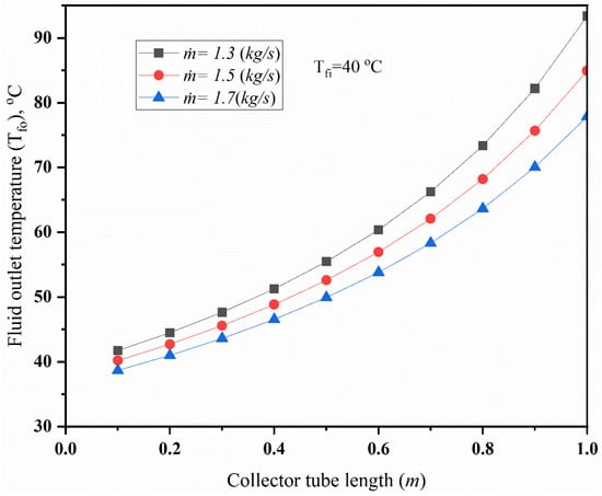
Figure 10.
Collector fluid outlet temperature as a function of tube length.
4. Conclusions
The present paper investigates analytically the performance of a two-dimensional liquid flat-plate collector with a nonlinear temperature variation at the plate–tube junction under steady-state conditions. The results of the analytical method agree with those of the numerical method used for validation. The predicted temperature distributions are in excellent agreement with each other. The marginal variations in efficiency on the conductivity of the plate material suggest that collector plates could be made of less expensive materials, such as aluminum, rather than copper. Even though the one-dimensional model performs well enough for engineering design purposes, a two-dimensional model is described here for developing an actual model, which is extremely important in the collector analysis.
Author Contributions
Methodology, J.M. and B.K.; Software, J.M.; Validation, J.M.; Investigation, J.M. and B.K.; Resources, B.K.; Data curation, J.M.; Writing—original draft, J.M.; Writing—review & editing, B.K.; Visualization, B.K.; Supervision, B.K. All authors have read and agreed to the published version of the manuscript.
Funding
This research received no external funding.
Data Availability Statement
The original contributions presented in the study are included in the article, further inquiries can be directed to the corresponding author.
Conflicts of Interest
The authors declare no conflict of interest.
Nomenclature
| dimensionless constant | |
| dimensionless constant | |
| normalized constant | |
| fluid-carrying tube length (m) | |
| half-pitch length between two tubes (m) | |
| Tube outer diameter(m) | |
| Tube inner diameter(m) | |
| heat conductivity (W m−1 K−1) | |
| convective coefficient at tube inner surface | |
| Mass transfer rate in the tube [kg/s] | |
| Biot number | |
| normalized thermo-geometric parameter | |
| normalized flux | |
| absorbed sun energy flux (W m−2) | |
| absorber temperature (local) (°C) | |
| ambient temperature (°C) | |
| absorber thickness (m) | |
| overall energy loss coefficient (W m−2 K−1) | |
| normalized coordinate, | |
| cartesin coordinate (m) | |
| normalized coordinate, | |
| cartesian -coordinate (m) | |
| thermo-geometric parameter | |
| efficiency factor | |
| normalized heat removal parameter | |
| collector fluid inlet temperature (°C) | |
| collector fluid outlet temperature (°C) | |
| absorber plate area (m2) | |
| collector gross area (m2) | |
| collector fluid specific heat (W kg−1 K−1) | |
| useful energy gain (W) | |
| sun radiation intensity (W/m2) | |
| Greek Symbols | |
| Width to length ratio of absorber plate | |
| dimensionless temperature | |
| plate efficiency factor | |
| Eigen constant | |
| collector efficiency | |
| transmissivity | |
| absorber plate absorptivity | |
| Subscripts | |
| inlet condition | |
References
- Kumar, L.; Hasanuzzaman, M.; Rahim, N.A. Global advancement of solar thermal energy technologies for industrial process heat and its future prospects: A review. Energy Convers. Manag. 2019, 195, 885–908. [Google Scholar] [CrossRef]
- Estevão, J.; Lopes, J.D. SDG7 and renewable energy consumption: The influence of energy sources. Technol. Forecast. Soc. Chang. 2024, 198, 123004. [Google Scholar] [CrossRef]
- Mahakud, J.; Kundu, B. Trapezoidal Approach to Establish One-Dimensional Analysis of an Absorber Plate for Two-Dimensional Heat Flow. In Advances in Mechanical Engineering: Select Proceedings of ICRIDME 2018; Springer: Singapore, 2020; pp. 1361–1372. [Google Scholar]
- Kundu, B.; Mondal, P.K.; Datta, S.P.; Wongwises, S. Operating design conditions of a solar-powered vapor absorption cooling system with an absorber plate having different profiles: An analytical study. Int. Commun. Heat Mass Transf. 2010, 37, 1238–1245. [Google Scholar] [CrossRef]
- Sukhatme, S.P.; Nayak, J. Solar Energy Principles of Thermal Collection and Storage, 3rd ed.; McGraw-Hill Education: New York, NY, USA, 2010. [Google Scholar]
- Hottel, H.C.; Woertz, B.S. The performance of flat plate solar heat collectors. Trans. Am. Soc. Mech. Eng. 1942, 64, 91–104. [Google Scholar] [CrossRef]
- Hottel, H.C.; Whillier, A. Evaluation of Flat-Plate Collector Performance. In Transactions of the Conference on the Use of Solar Energy; University of Arizona Press: Tuscan, AZ, USA, 1958; Volume 2, p. 74. [Google Scholar]
- Bliss, R.W. The Derivations of Several Plate-Efficiency Factors Useful in the Design of Flat-Plate Solar Heat Collectors. Sol. Energy 1959, 3, 55–69. [Google Scholar] [CrossRef]
- Duffie, J.A.; Beckman, W.A. Solar Energy Thermal Processes; Wiley: New York, NY, USA, 1974. [Google Scholar]
- Kundu, B. Performance analysis and optimization of absorber plates of different geometry for a flat-plate solar collector: A comparative study. Appl. Therm. Eng. 2002, 22, 999–1012. [Google Scholar] [CrossRef]
- Kundu, B. The influence of collector fluid inlet temperature on the performance of a solar-assisted absorption system using step-finned flat-plate collector. Heat Transf. Eng. 2007, 28, 496–505. [Google Scholar] [CrossRef]
- Kundu, B. Performance and optimum design analysis of an absorber plate fin using recto-trapezoidal profile. Sol. Energy 2008, 82, 22–32. [Google Scholar] [CrossRef]
- Hollands, K.G.T.; Stedman, B.A. Optimization of an absorber plate fin having a step change in local thickness. Sol. Energy 1992, 49, 493–495. [Google Scholar] [CrossRef]
- Kundu, B. Analytic method for thermal performance and optimization of an absorber plate fin having variable thermal conductivity and overall loss coefficient. Appl. Energy 2010, 87, 2243–2255. [Google Scholar] [CrossRef]
- Nayak, J.K.; Amer, E.H. Experimental and theoretical evaluation of dynamic test procedures for solar flat-plate collectors. Sol. Energy 2000, 69, 377–401. [Google Scholar] [CrossRef]
- Kalogirou, S.A. Prediction of flat-plate collector performance parameters using artificial neural networks. Sol. Energy 2006, 80, 248–259. [Google Scholar] [CrossRef]
- Mausam, K.; Singh, S.; Ghosh, S.K.; Singh, R.P. Thermal performance modelling of solar flat plate parallel tube collector using ANN. Energy 2024, 303, 131940. [Google Scholar] [CrossRef]
- Mohseni-Gharyehsafa, B.; Esfahani, J.A.; Kim, K.C.; Ouerdane, H. Soft computing analysis of thermohydraulic enhancement using twisted tapes in a flat-plate solar collector: Sensitivity analysis and multi-objective optimization. J. Clean. Prod. 2021, 314, 127947. [Google Scholar] [CrossRef]
- Alawi, O.A.; Kamar, H.M.; Salih, S.Q.; Abba, S.I.; Ahmed, W.; Homod, R.Z.; Jamei, M.; Shafik, S.S.; Yaseen, Z.M. Development of optimized machine learning models for predicting flat plate solar collectors thermal efficiency associated with Al2O3-water nanofluids. Eng. Appl. Artif. Intell. 2024, 133, 108158. [Google Scholar] [CrossRef]
- Filipović, P.; Dović, D.; Horvat, I.; Ranilović, B. Evaluation of a novel polymer solar collector using numerical and experimental methods. Energy 2023, 284, 128558. [Google Scholar] [CrossRef]
- Bao, Y.; Chen, J.; Shao, S. Comparison on thermal and hydraulic performances of transverse mini-channel based on a novel comprehensive evaluation factor. Appl. Therm. Eng. 2024, 253, 123795. [Google Scholar] [CrossRef]
- Bharathiraja, R.; Ramkumar, T.; Karthick, L.; Mohanraj, M. Performance investigation on flat plate solar water collector using a hybrid nano-enhanced phase change material (PCM). J. Energy Storage 2024, 86, 111163. [Google Scholar] [CrossRef]
- Bhowmik, H.; Amin, R. Efficiency improvement of flat plate solar collector using reflector. Energy Rep. 2017, 3, 119–123. [Google Scholar] [CrossRef]
- Garcia, R.P.; del Rio Oliveira, S.; Scalon, V.L. Thermal efficiency experimental evaluation of solar flat plate collectors when introducing convective barriers. Sol. Energy 2019, 182, 278–285. [Google Scholar] [CrossRef]
- Zheng, J.; Febrer, R.; Castro, J.; Kizildag, D.; Rigola, J. A new high-performance flat plate solar collector. Numerical modelling and experimental validation. Appl. Energy 2024, 355, 122221. [Google Scholar] [CrossRef]
- He, Y.; Yu, H.; Duan, G.; Wang, Y.; Yang, Q.; Feng, L.; Zhang, J. Thermal performance and experimental analysis of stainless steel flat plate solar collector with full-flow channels. Heliyon 2024, 10, e28255. [Google Scholar] [CrossRef] [PubMed]
- Verma, S.K.; Tiwari, A.K. Progress of nanofluid application in solar collectors: A review. Energy Convers. Manag. 2015, 100, 324–346. [Google Scholar] [CrossRef]
- Elcioglu, E.B.; Genc, A.M.; Karadeniz, Z.H.; Ezan, M.A.; Turgut, A. Nanofluid figure-of-merits to assess thermal efficiency of a flat plate solar collector. Energy Convers. Manag. 2020, 204, 112292. [Google Scholar] [CrossRef]
- Akram, N.; Montazer, E.; Kazi, S.N.; Soudagar, M.E.M.; Ahmed, W.; Zubir, M.N.M.; Afzal, A.; Muhammad, M.R.; Ali, H.M.; Márquez, F.P.G.; et al. Experimental investigations of the performance of a flat-plate solar collector using carbon and metal oxides based nanofluids. Energy 2021, 227, 120452. [Google Scholar] [CrossRef]
- Ajeena, A.M.; Víg, P.; Farkas, I. A comprehensive analysis of nanofluids and their practical applications for flat plate solar collectors: Fundamentals, thermophysical properties, stability, and difficulties. Energy Rep. 2022, 8, 4461–4490. [Google Scholar] [CrossRef]
- Demirdelen, T.; Alıcı, H.; Esenboğa, B.; Güldürek, M. Performance and economic analysis of designed different solar tracking systems for Mediterranean climate. Energies 2023, 16, 4197. [Google Scholar] [CrossRef]
- Desisa, T.R. Experimental and numerical investigation of heat transfer characteristics in solar flat plate collector using nanofluids. Int. J. Thermofluids 2023, 18, 100325. [Google Scholar] [CrossRef]
- Zima, W.; Mika, Ł.; Sztekler, K. Numerical and Experimental Determination of Selected Performance Indicators of the Liquid Flat-Plate Solar Collector under Outdoor Conditions. Energies 2024, 17, 3454. [Google Scholar] [CrossRef]
- Kundu, B.; Lee, K.S. Fourier and non-Fourier heat conduction analysis in the absorber plates of a flat-plate solar collector. Sol. Energy 2012, 86, 3030–3039. [Google Scholar] [CrossRef]
- Kalogirou, S.A.; Karellas, S.; Braimakis, K.; Stanciu, C.; Badescu, V. Exergy analysis of solar thermal collectors and processes. Prog. Energy Combust. Sci. 2016, 56, 106–137. [Google Scholar] [CrossRef]
- Mostafizur, R.M.; Rasul, M.G.; Nabi, M.N. Energy and exergy analyses of a flat plate solar collector using various nanofluids: An analytical approach. Energies 2021, 14, 4305. [Google Scholar] [CrossRef]
- Wciślik, S.; Taler, D. Economic and Exergy Analysis of TiO2 + SiO2 Ethylene-Glycol-Based Hybrid Nanofluid in Plate Heat Exchange System of Solar Installation. Energies 2024, 17, 3107. [Google Scholar] [CrossRef]
- Rao, P.P.; Francis, J.E.; Love, T.J. Two-dimensional analysis of a flat-plate solar collector. J. Energy 1977, 1, 324–328. [Google Scholar] [CrossRef]
- Lund, K.O. General thermal analysis of parallel-flow flat-plate solar collector absorbers. Sol. Energy 1986, 5, 443. [Google Scholar] [CrossRef]
- Nag, A.; Misra, D.; De, K.E.; Bhattacharya, A.; Saha, S.K. Study of parallel flow flat plate solar collector using finite element method. In Numerical Methods in Thermal Problems, Proceedings of the 6th International Conference, Swansea, UK, 3–7 July 1989; The College, Swansea University: Swansea, UK, 1989. [Google Scholar]
- Kazeminejad, H. Numerical analysis of two dimensional parallel flow flat-plate solar collector. Renew. Energy 2002, 26, 2309–2323. [Google Scholar] [CrossRef]
- Cerón, J.F.; Pérez-García, J.; Solano, J.P.; García, A.; Herrero-Martín, R. A coupled numerical model for tube-on-sheet flat-plate solar liquid collectors. Analysis and validation of the heat transfer mechanisms. Appl. Energy 2015, 140, 275–287. [Google Scholar] [CrossRef]
- Quitiaquez, W.; Estupiñán-Campos, J.; Nieto-Londoño, C.; Quitiaquez, P. CFD Analysis of Heat Transfer Enhancement in a Flat-Plate Solar Collector/Evaporator with Different Geometric Variations in the Cross Section. Energies 2023, 16, 5755. [Google Scholar] [CrossRef]
- García-Guendulain, J.M.; Riesco-Avila, J.M.; Elizalde-Blancas, F.; Belman-Flores, J.M.; Serrano-Arellano, J. Numerical study on the effect of distribution plates in the manifolds on the flow distribution and thermal performance of a flat plate solar collector. Energies 2018, 11, 1077. [Google Scholar] [CrossRef]
- Kundu, B.; Das, P.K. Optimum dimensions of plate fins for fin-tube heat exchangers. Int. J. Heat Fluid Flow 1997, 18, 530–537. [Google Scholar] [CrossRef]
- Kundu, B.; Lee, K.S. A non-Fourier analysis for transmitting heat in fins with internal heat generation. Int. J. Heat Mass Transf. 2013, 64, 1153–1162. [Google Scholar] [CrossRef]
- Patankar, S.V. Numerical Heat Transfer and Fluid Flow; Hemisphere Publishing, Taylor and Francis Group: New York, NY, USA, 1980. [Google Scholar]
Disclaimer/Publisher’s Note: The statements, opinions and data contained in all publications are solely those of the individual author(s) and contributor(s) and not of MDPI and/or the editor(s). MDPI and/or the editor(s) disclaim responsibility for any injury to people or property resulting from any ideas, methods, instructions or products referred to in the content. |
© 2024 by the authors. Licensee MDPI, Basel, Switzerland. This article is an open access article distributed under the terms and conditions of the Creative Commons Attribution (CC BY) license (https://creativecommons.org/licenses/by/4.0/).