
Study on the Resonance Characteristics and Active Damping Suppression Strategies of Multi-Inverter Grid-Connected Systems Under Weak Grid Conditions

Abstract
1. Introduction
2. Literature Review
3. Modeling and Resonance Characterization of Multi-Converter Systems with LCL Topology
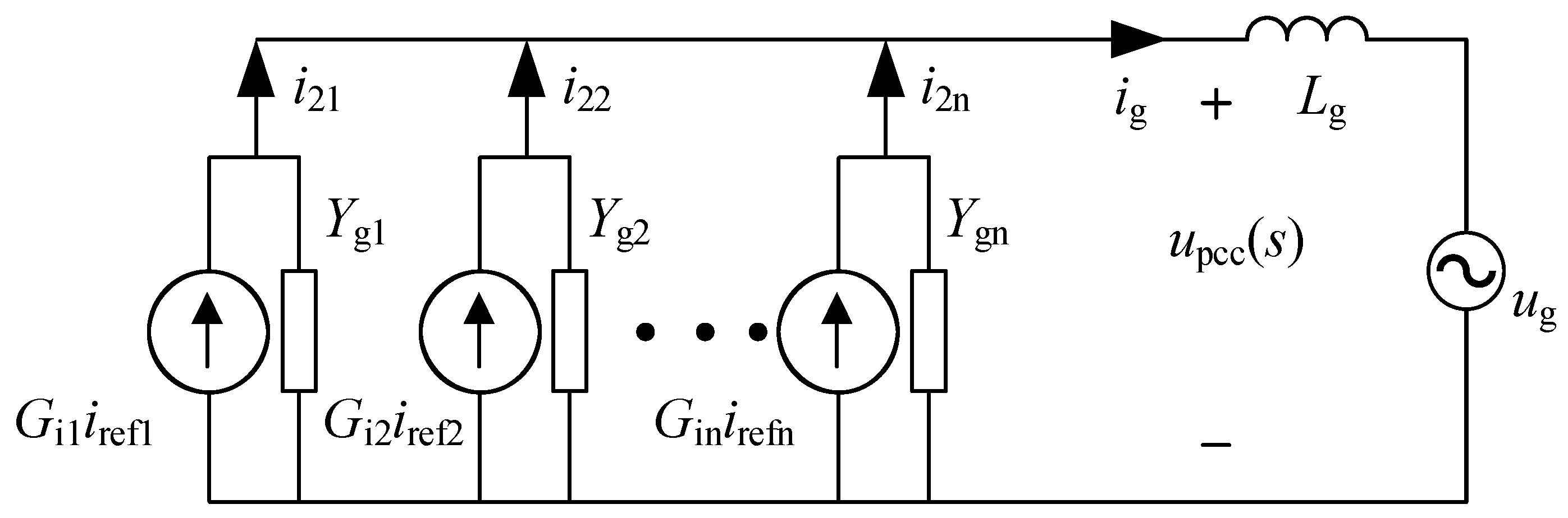
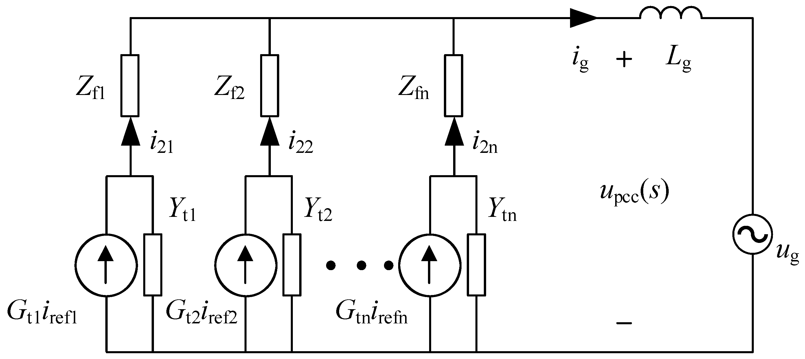
3.1. System Modeling Considering Parasitic Parameters
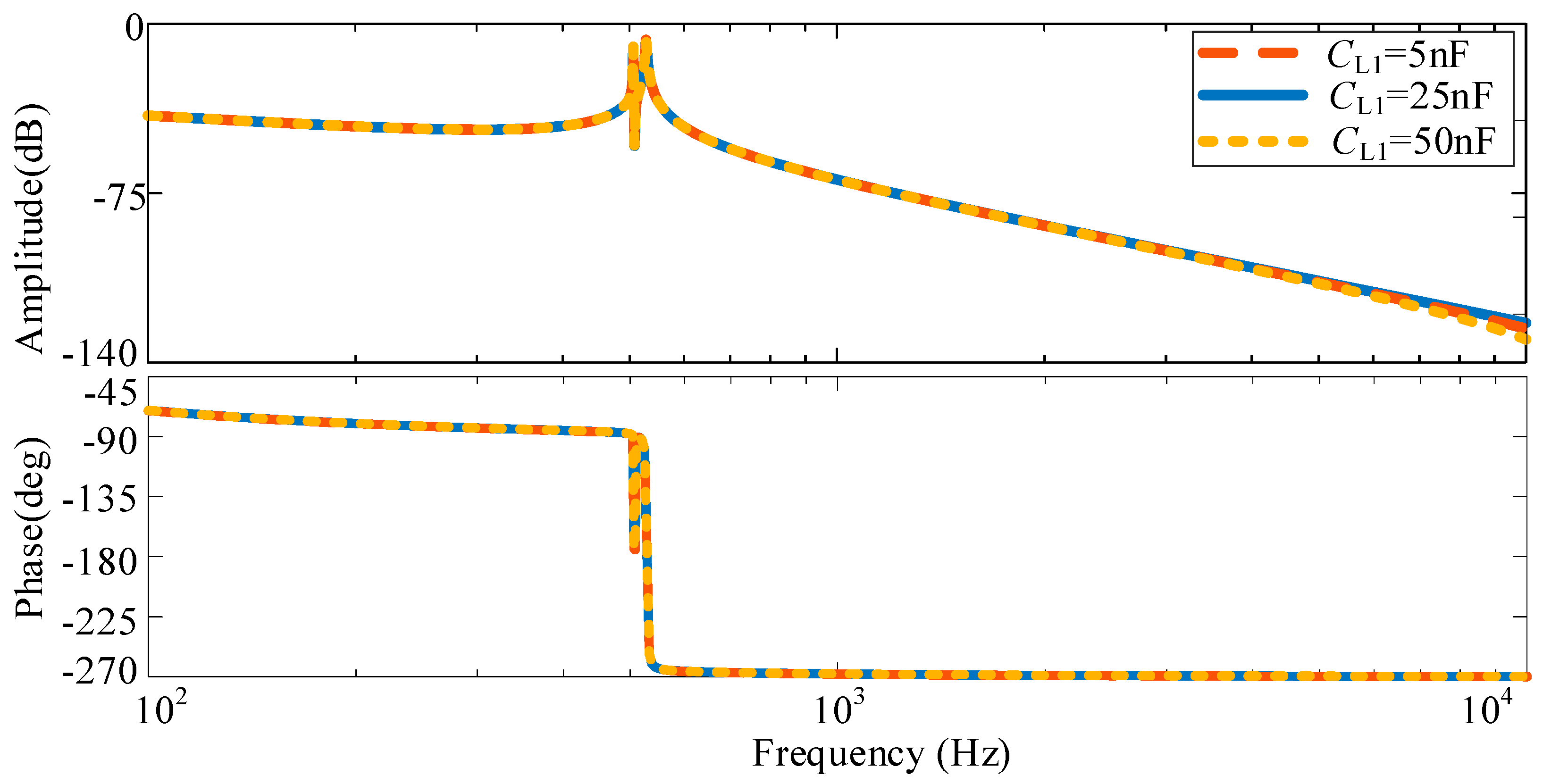
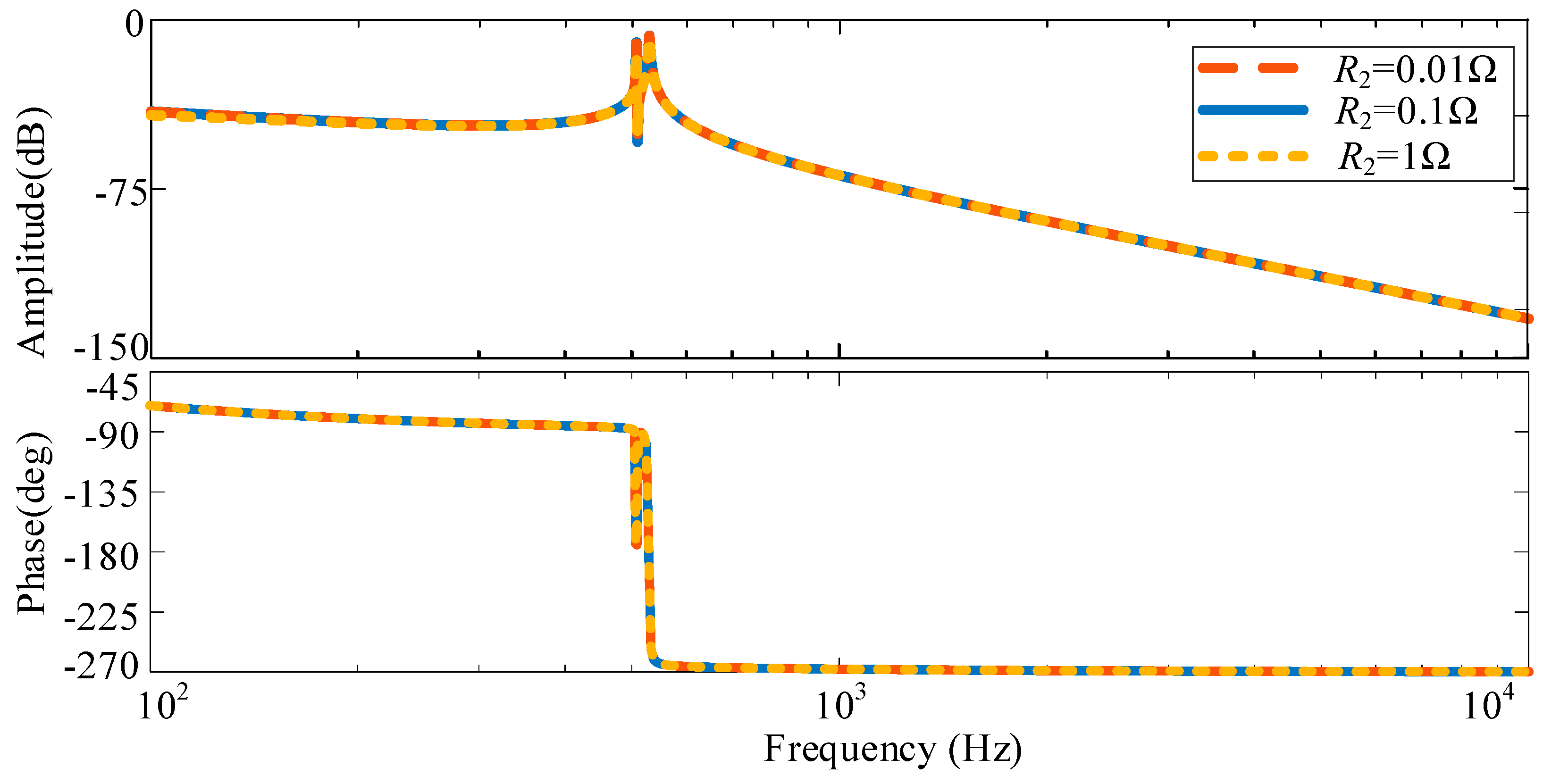
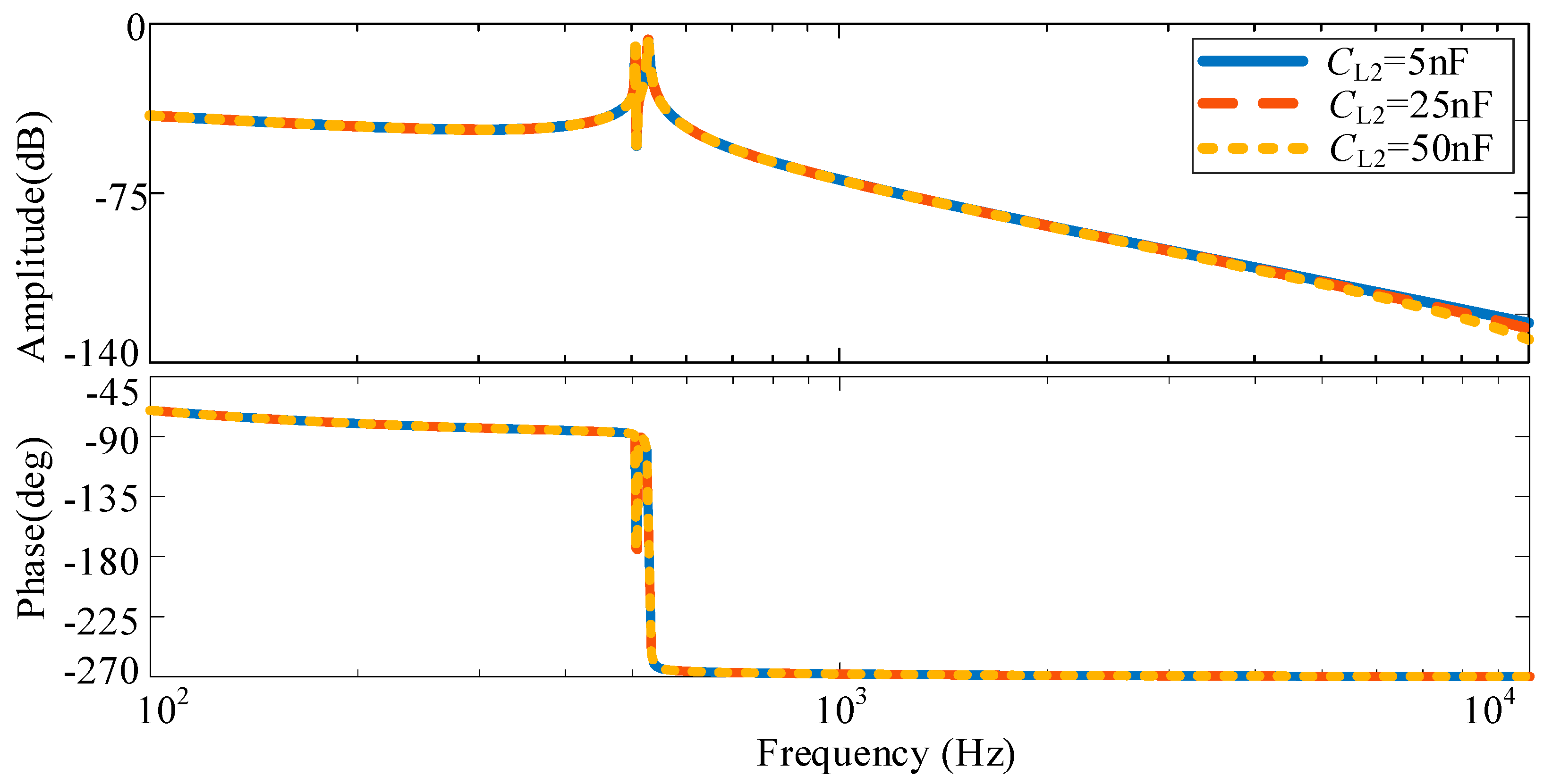
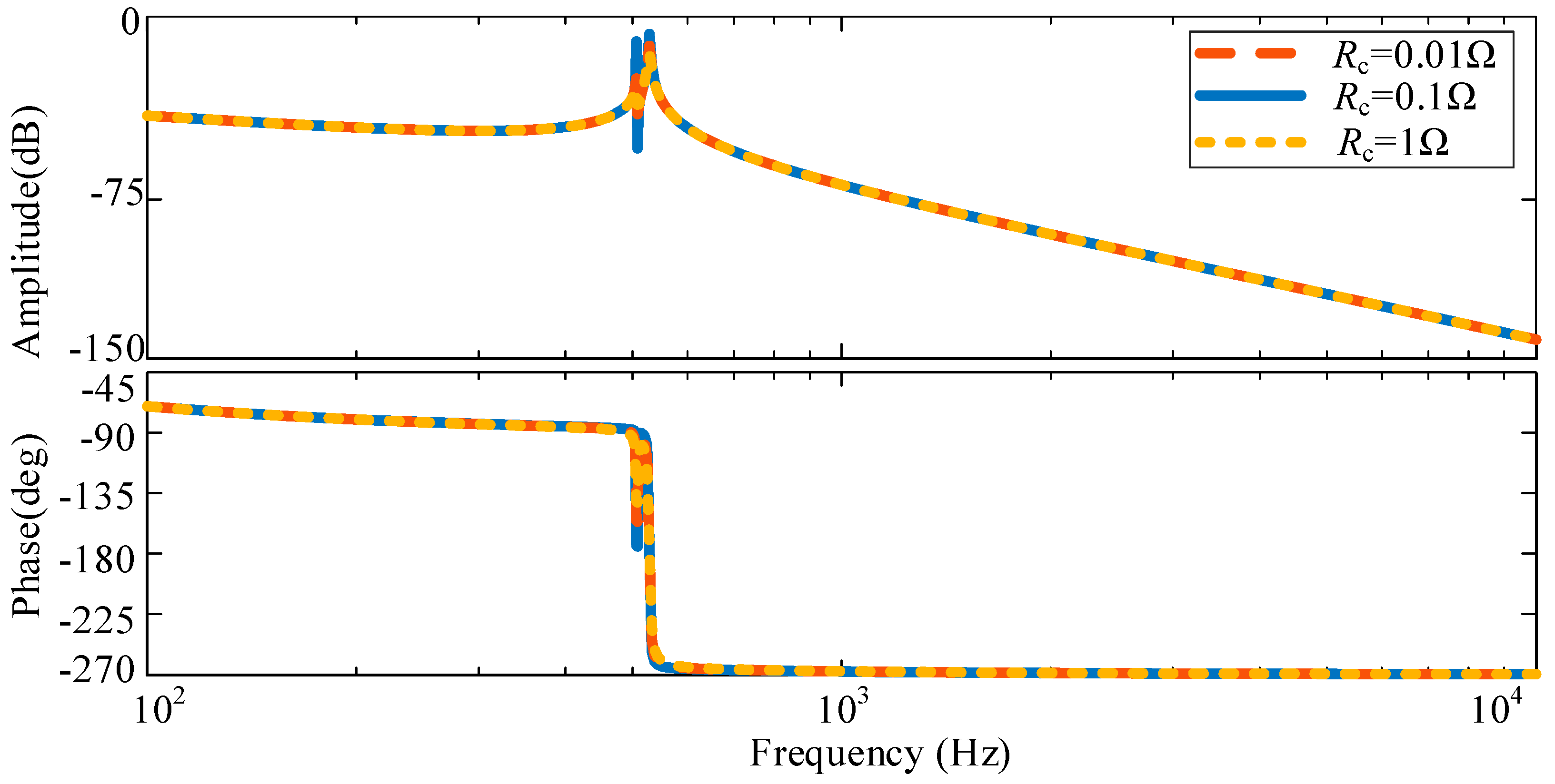
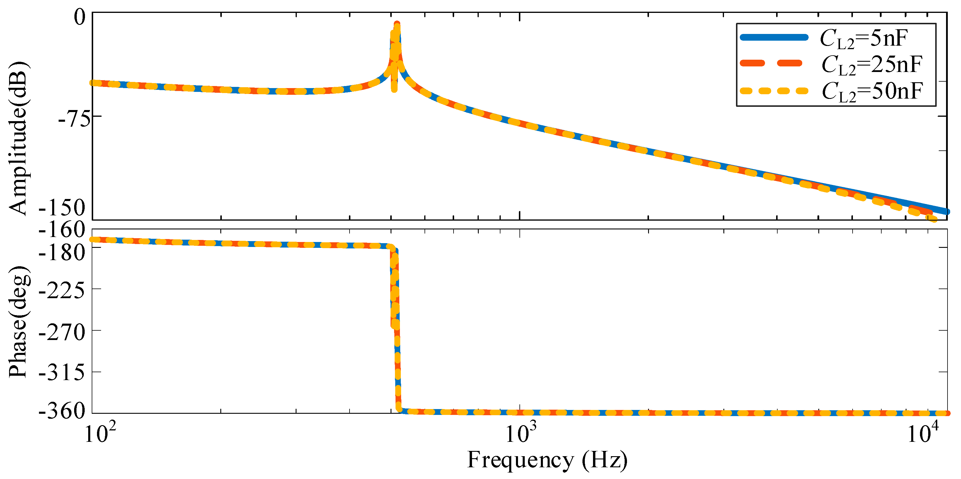
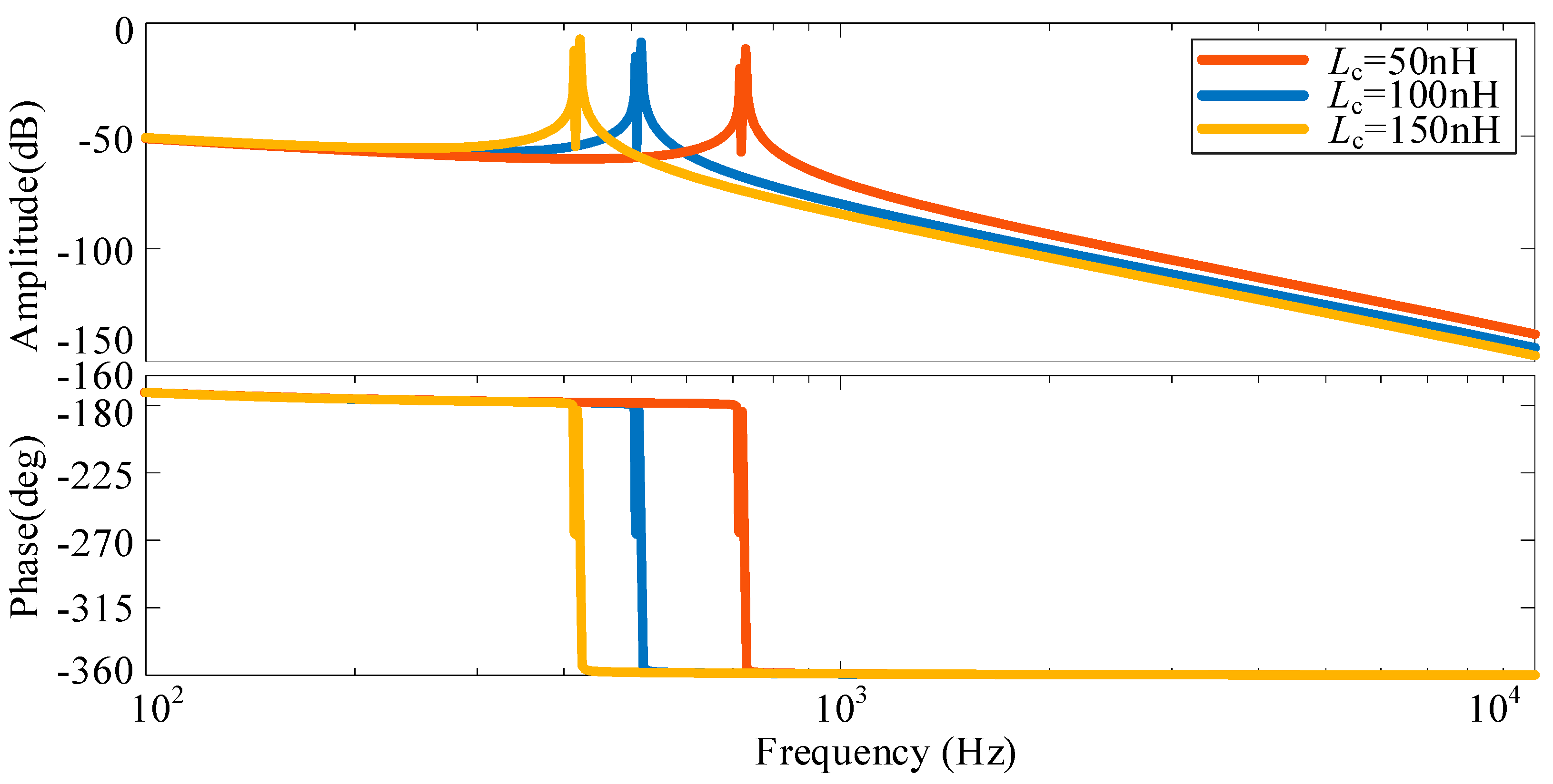
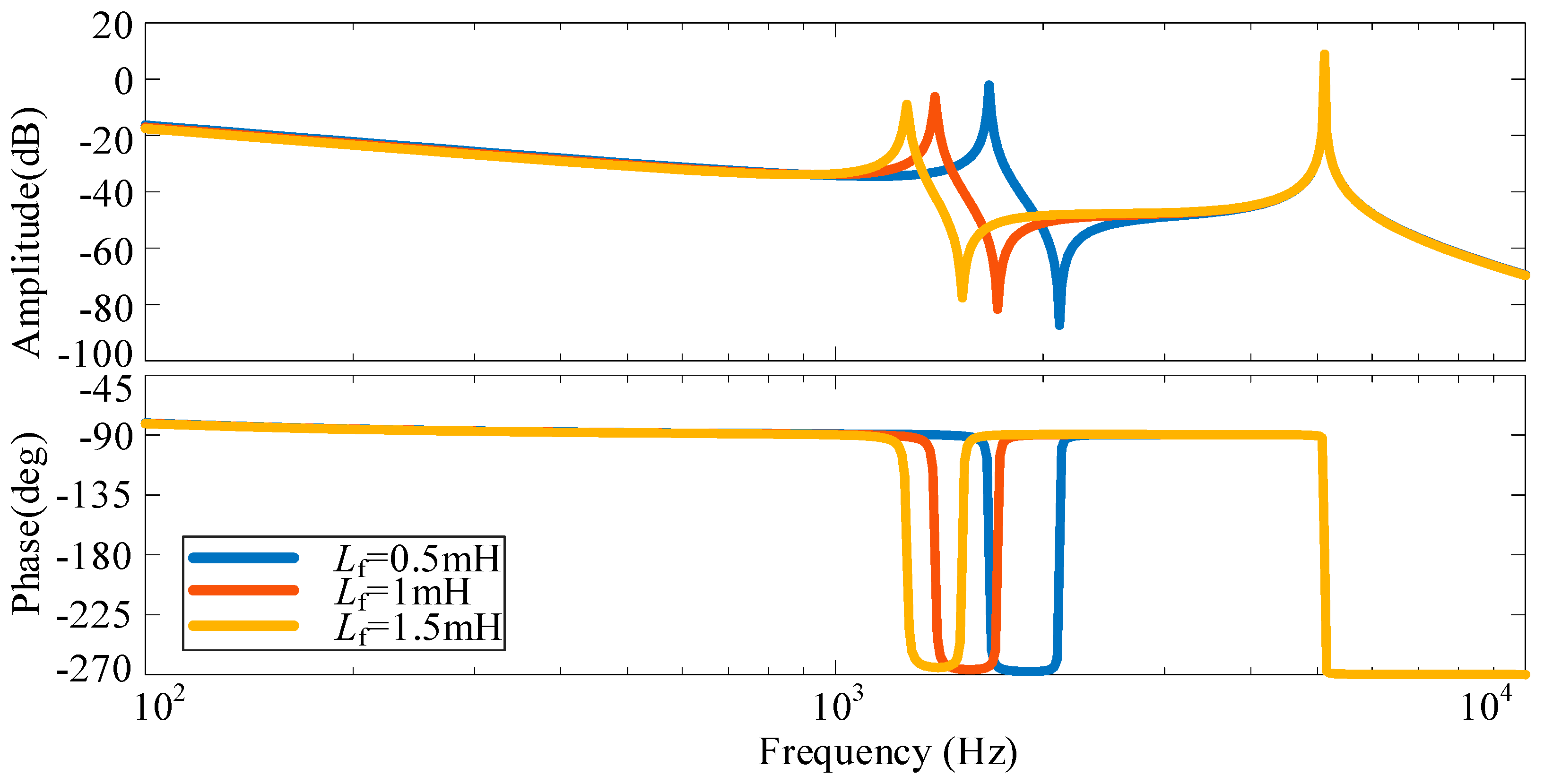
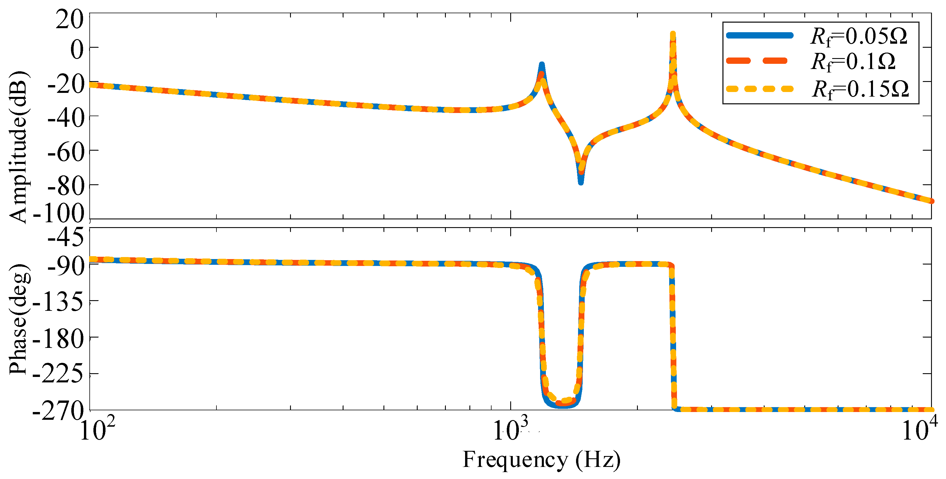
3.2. Analysis of System Resonance Characteristics Considering Parasitic Parameters
3.2.1. Analysis of System Resonance Characteristics with Two Identical Parameter Inverters
3.2.2. Analysis of System Resonance Characteristics with Two Different Parameter Inverters
3.3. System Modeling Considering Line Impedance
3.4. Analysis of System Resonance Characteristics Considering Line Impedance
3.4.1. Analysis of System Resonance Characteristics with Two Identical Parameter Inverters
3.4.2. Analysis of System Resonance Characteristics with Two Different Parameter Inverters
4. Active Damping Strategy Design and Simulation Results
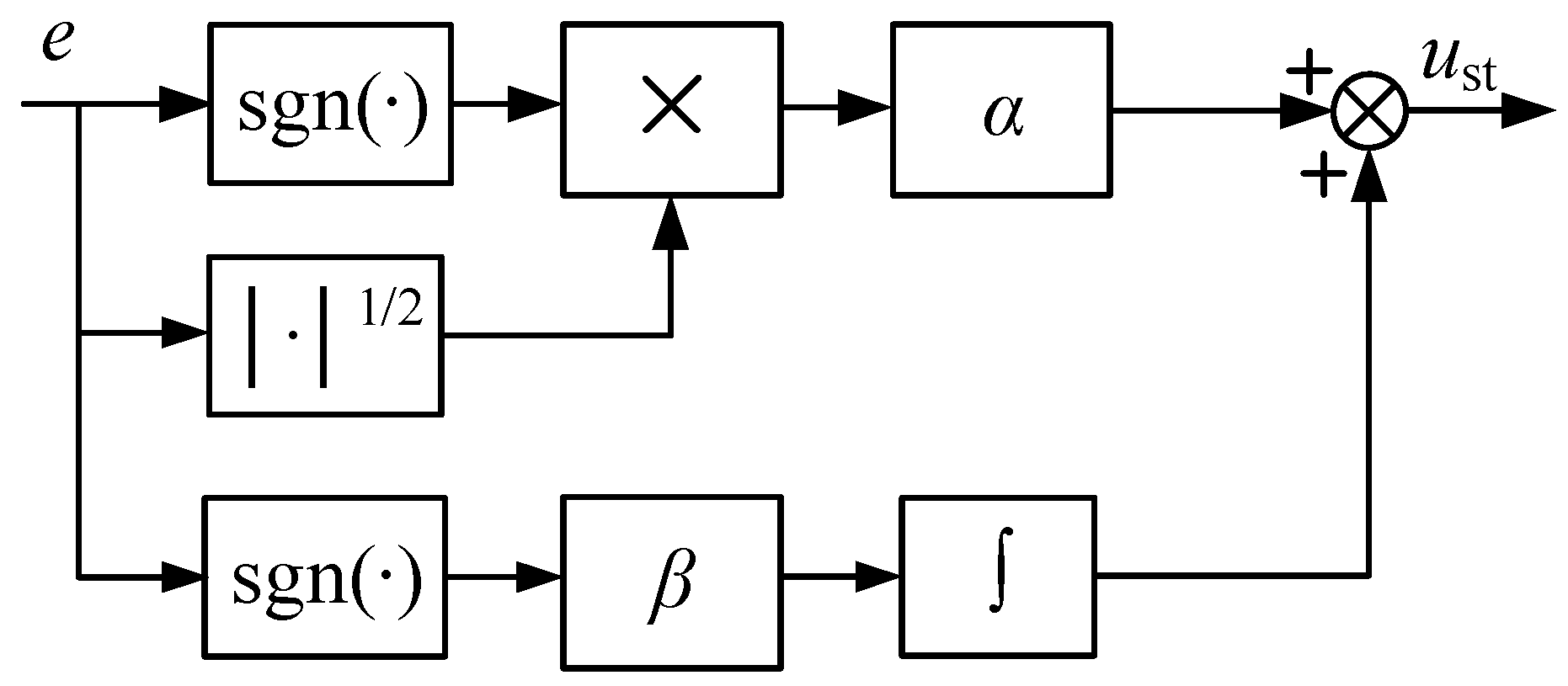
4.1. Active Damping Strategy Design
4.2. Simulation Results
- (1)
- Without Resonance Suppression Strategy
- (2)
- Using the PI Control-Based Active Damping Resonance Suppression Strategy
- (3)
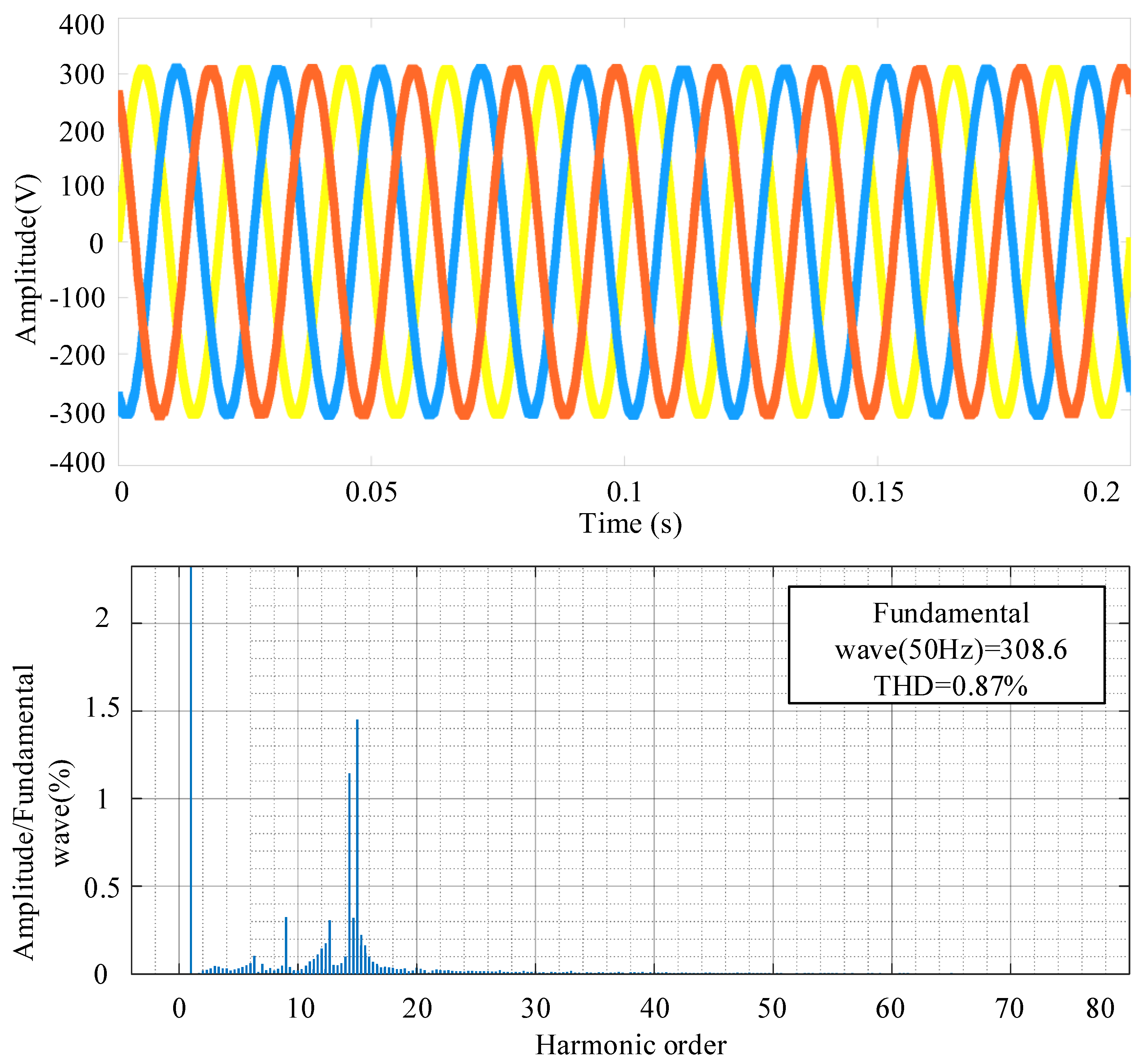
- Using the Improved Active Damping Resonance Suppression Strategy
- (1)
- Without Resonance Suppression Strategy
- (2)
- Using the PI Control-Based Active Damping Resonance Suppression Strategy
- (3)
- Using the Improved Active Damping Resonance Suppression Strategy
5. Conclusions
Author Contributions
Funding
Data Availability Statement
Conflicts of Interest
References
- Mohammed, N.; Kerekes, T.; Ciobotaru, M. Communication-free equivalent grid impedance estimation technique for multi-inverter systems. IEEE Trans. Ind. Electron. 2023, 70, 1542–1552. [Google Scholar] [CrossRef]
- Qin, B.; Xu, Y.; Yuan, C.; Jia, J. A unified method of frequency oscillation characteristic analysis for multi-VSG grid-connected system. IEEE Trans. Power Deliv. 2022, 37, 279–289. [Google Scholar] [CrossRef]
- Antoine, M.; Li, H.; Zheng, X.; Yu, Y. Multivariable state-feedback controller design for PV inverter connected to a weak grid. Energies 2021, 14, 4441. [Google Scholar] [CrossRef]
- Cheng, C.; Xie, S.; Xu, J.; Qian, Q. Universal absolute stability criterion for single-phase grid-following inverters equipped with orthogonal-normalization-based grid synchronizer. IEEE Trans. Power Electron. 2023, 38, 9090–9099. [Google Scholar] [CrossRef]
- Li, H.; Ding, X.; Xue, R.; Li, G.; Chen, Y. Active damping adaptive controller for grid-connected inverter under weak grid. IEEE Access 2021, 9, 132442–132454. [Google Scholar] [CrossRef]
- Shi, J.; Yang, L.; Yang, H. Impedance-based stability analysis of grid-connected inverters under the unbalanced grid condition. Appl. Sci. 2023, 13, 12441. [Google Scholar] [CrossRef]
- Zhao, Q.; Liu, K.; Li, H. A fractional-order multi-rate repetitive controller for single-phase grid-connected inverters. Electronics 2023, 12, 1021. [Google Scholar] [CrossRef]
- Ma, G.; Xie, C.; Li, C.; Zou, J.; Guerrero, J.M. Passivity-based design of passive damping for LCL-type grid-connected inverters to achieve full-frequency passive output admittance. IEEE Trans. Power Electron. 2023, 38, 16048–16060. [Google Scholar] [CrossRef]
- Upadhyay, N.; Padhy, N.P.; Agarwal, P. Exploring inherent harmonic attenuation capabilities of proportional active damping for LCL grid connected inverter. IEEE Trans. Ind. Appl. 2022, 29, 575–580. [Google Scholar]
- Jo, J.; Cha, H. Design of effective passive damping resistor of grid-connected inverter with LCL filter for industrial applications. J. Electr. Eng. Technol. 2019, 14, 2039–2048. [Google Scholar] [CrossRef]
- Wang, S.; Cui, K.; Hao, P. Grid-connected inverter grid voltage feedforward control strategy based on multi-objective constraint in weak grid. Energies 2024, 17, 3288. [Google Scholar] [CrossRef]
- Xie, C.; Li, K.; Zou, J.; Liu, D.; Guerrero, J.M. Passivity-based design of grid-side current-controlled LCL-type grid-connected inverters. IEEE Trans. Power Electron. 2020, 35, 9813–9823. [Google Scholar] [CrossRef]
- Ali azghandi, M.; Masoud barakati, S.; Yazdani, A. Impedance-based stability analysis and design of a fractional-order active damper for grid-connected current-source inverters. IEEE Trans. Sustain. Energy 2021, 12, 599–611. [Google Scholar] [CrossRef]
- Zhang, X.; Chen, P.; Yu, C.; Li, F.; Do, H.T.; Cao, R. Study of a current control strategy based on multisampling for high-power grid-connected inverters with an LCL filter. IEEE Trans. Power Electron. 2017, 32, 5023–5034. [Google Scholar] [CrossRef]
- Zhao, J.; Xie, C.; Li, K.; Zou, J.; Guerrero, J.M. Passivity-oriented design of LCL-type grid-connected inverters with luenberger observer-based active damping. IEEE Trans. Power Electron. 2022, 37, 2625–2635. [Google Scholar] [CrossRef]
- Ma, W.; Guan, Y.; Zhang, B.; Wu, L. Active disturbance rejection control based single current feedback resonance damping strategy for LCL-type grid-connected inverter. IEEE Trans. Energy Convers. 2021, 36, 48–62. [Google Scholar] [CrossRef]
- Akhavan, A.; Mohammadi, H.R.; Guerrero, J.M. A comprehensive control system for multi-parallel grid-connected inverters with LCL filter in weak grid condition. Electr. Power Syst. Res. 2018, 163, 288–300. [Google Scholar] [CrossRef]
- Guo, Y.; Lu, X.; Chen, L.; Zheng, T.; Wang, J.; Mei, S. Functional-rotation-based active dampers in ac microgrids with multiple parallel interface inverters. IEEE Trans. Ind. Appl. 2018, 54, 5206–5215. [Google Scholar] [CrossRef]
- Fang, T.; Shen, S.; Jin, Y.; Ruan, X. Robustness investigation of multi-inverter paralleled grid-connected system with LCL-Filter based on the grid-impedance allocation mechanism. IEEE Trans. Power Electron. 2021, 36, 14508–14524. [Google Scholar] [CrossRef]
- Babu, N.; Padhy, N.P. An approach to improve harmonic attenuation and stability performance in multi-parallel inverter system. IEEE Trans. Power Deliv. 2023, 38, 3634–3646. [Google Scholar] [CrossRef]
- Zhou, X.; Xu, D.; Huang, Y. Harmonic interaction analysis between multi-inverter system and power grid based on equivalent single-inverter model. J. Electr. Eng. Technol. 2022, 18, 193–203. [Google Scholar] [CrossRef]
- Akhavan, A.; Vasquez, J.C.; Guerrero, J.M. Stability analysis of parallel grid-forming inverters in asymmetrical conditions. IEEE J. Emerg. Sel. Top. Ind. Electron. 2024, 5, 1344–1348. [Google Scholar] [CrossRef]
- Zeng, C.; Wu, X.; Miao, H.; Duan, H. Responsibility division for harmonic instability in the multi-paralleled grid-connected inverters system based on impedance analysis. IEEE Access 2023, 11, 115450–115461. [Google Scholar] [CrossRef]
- Li, M.; Geng, H.; Zhang, X. Hierarchical mode-dispatching control for multi-inverter power stations. IEEE Trans. Ind. Electron. 2023, 70, 10044–10054. [Google Scholar] [CrossRef]
- Li, M.; Geng, H.; Zhang, X. Distributed coordinated control for stabilization of multi-inverter power plant. IEEE Trans. Ind. Electron. 2023, 70, 12421–12430. [Google Scholar] [CrossRef]
- Zhang, M.; Wang, J.; Zhang, S.; Gao, L.; Guo, X.; Chen, L.; Xu, Y. Harmonic resonance analysis and impedance remodeling method of multi-inverter grid-connected system. Electronics 2023, 12, 3684. [Google Scholar] [CrossRef]
- Khajeh, K.G.; Solatialkaran, D.; Zare, F.; Farajizadeh, F.; Yaghoobi, J.; Nadarajah, M. A harmonic mitigation technique for multi-parallel grid-connected inverters in distribution networks. IEEE Trans. Power Deliv. 2022, 37, 2843–2856. [Google Scholar] [CrossRef]


| Parameters | Value |
|---|---|
| Inverter-side inductance, L1 | 3 mH |
| Integral coefficient, Ki | 2200 |
| Filter capacitor, C | 10 μF |
| Inverter power, Po | 30 kW |
| Grid-side inductance, L2 | 1 mH |
| Grid voltage, ug | 311 V |
| Proportional coefficient, KP | 0.35 |
| Grid reactance, Lg | 0.5 mH |
| Switching frequency, fsw | 10 kHz |
| DC-side voltage, udc | 800 V |
| Parameters | Value |
|---|---|
| Inverter-side inductance, L1 | 6 mH |
| Integral coefficient, Ki | 4000 |
| Filter capacitor, C | 15 μF |
| Inverter power, Po | 30 kW |
| Grid-side inductance, L2 | 3 mH |
| Grid voltage, ug | 311 V |
| Proportional coefficient, KP | 0.6 |
| Grid reactance, Lg | 0.5 mH |
| Switching frequency, fsw | 10 kHz |
| DC-side voltage, udc | 800 V |
Disclaimer/Publisher’s Note: The statements, opinions and data contained in all publications are solely those of the individual author(s) and contributor(s) and not of MDPI and/or the editor(s). MDPI and/or the editor(s) disclaim responsibility for any injury to people or property resulting from any ideas, methods, instructions or products referred to in the content. |
© 2024 by the authors. Licensee MDPI, Basel, Switzerland. This article is an open access article distributed under the terms and conditions of the Creative Commons Attribution (CC BY) license (https://creativecommons.org/licenses/by/4.0/).
Share and Cite
Hou, T.; Jiang, Y.; Cai, Z. Study on the Resonance Characteristics and Active Damping Suppression Strategies of Multi-Inverter Grid-Connected Systems Under Weak Grid Conditions. Energies 2024, 17, 5889. https://doi.org/10.3390/en17235889
Hou T, Jiang Y, Cai Z. Study on the Resonance Characteristics and Active Damping Suppression Strategies of Multi-Inverter Grid-Connected Systems Under Weak Grid Conditions. Energies. 2024; 17(23):5889. https://doi.org/10.3390/en17235889
Chicago/Turabian StyleHou, Tianhao, Yunhao Jiang, and Zishuo Cai. 2024. "Study on the Resonance Characteristics and Active Damping Suppression Strategies of Multi-Inverter Grid-Connected Systems Under Weak Grid Conditions" Energies 17, no. 23: 5889. https://doi.org/10.3390/en17235889
APA StyleHou, T., Jiang, Y., & Cai, Z. (2024). Study on the Resonance Characteristics and Active Damping Suppression Strategies of Multi-Inverter Grid-Connected Systems Under Weak Grid Conditions. Energies, 17(23), 5889. https://doi.org/10.3390/en17235889