Abstract
This paper presents a method to validate state of charge (SOC) estimations in batteries for their use in remotely manned aerial vehicles (UAVs). The SOC estimation must provide the mission control with a measure of the available range of the aircraft, which is critical for extended missions such as search and rescue operations. However, the uncertainty about the initial state and depth of discharge during the mission makes the estimation challenging. In order to assess the estimation provided to mission control, an a posteriori re-estimation is performed. This allows for the assessment of estimation methods. A reverse-time Kalman estimator is proposed for this task. Accurate SOC estimations are crucial for optimizing the utilization of multiple UAVs in a collaborative manner, ensuring the efficient use of energy resources and maximizing mission success rates. Experimental results for LiFePO4 batteries are provided, showing the capabilities of the proposal for the assessment of online SOC estimators.
1. Introduction
State of charge (SOC) estimation is an important topic for aerial applications using electric batteries. The state of charge (SOC) of UAV batteries is fundamental in determining the maximum operational range and duration of a UAV. Accurate SOC estimation allows mission planners to predict the UAV’s flight time and range, ensuring that the vehicle can complete its mission and return safely. For instance, UAV endurance and range calculations depend on factors such as battery capacity, motor current, aircraft size, and aerodynamic performance, making accurate SOC estimation essential for mission success [1].
Accurate SOC predictions are crucial for the success and safety of UAV missions. In critical operations, such as search and rescue (SAR), the UAV must reliably cover designated areas without interruption. The misestimation of SOC can lead to UAVs failing to return or running out of power mid-mission, potentially endangering lives and leading to mission failure. Studies have shown that incorporating advanced SOC estimation techniques can significantly enhance mission reliability and safety [2,3].
In search and rescue operations, UAVs play a critical role in locating and identifying survivors over vast and often challenging terrains. Accurate SOC estimation is vital in ensuring that UAVs can sustain long flights and maximize their coverage area, as a UAV running out of power prematurely could result in missed opportunities to locate survivors, highlighting the importance of precise SOC management. There are numerous real-world scenarios where inaccurate SOC estimations could lead to mission failures or safety risks. For instance, during the 2017 hurricanes in Puerto Rico, UAVs were deployed for damage assessment and Search and Rescue (SAR) missions, where inaccurate SOC estimations could have jeopardized these missions, leaving critical areas unassessed or missing survivors. Accurate SOC estimations are therefore essential in mitigating risks and ensuring mission success [4]. Using multiple UAVs collaboratively can significantly enhance mission efficiency and effectiveness. Accurate SOC estimations enable mission planners to optimize the deployment of UAVs, ensuring that each UAV can fulfill its designated role without risking premature battery depletion. Collaborative missions benefit from coordinated efforts, where UAVs with sufficient SOC can take over tasks from those with low SOC, maintaining continuous operation [2].
The estimation should provide a measure of how much energy is left in the battery to keep the system going, similar to the fuel indicator in a vehicle [5,6]. An accurate estimation is needed for safety concerns and also to maintain operational variables under control [7,8]. Also, some drive control methods make use of models of the available energy to improve reliability [9]. Finally, some electronic elements can be subject to design improvements considering a battery model [10].
Battery modeling is used to identify parameters from measurements [11]. It is well known that Coulomb counting methods provide direct estimations that are subject to sensor imperfections [12]. Incorporating other variables allows for more accurate estimations [13]. This is the case of the terminal voltage , which is linked to the Open Circuit Voltage (OCV), which in turn is linked to SOC via the OCV-SOC curve [14]. The Kalman state estimator and its variants have been proposed in many research works to improve the Coulomb counting method [15]. However, the use of terminal voltage as a proxy for SOC has some problems. Battery aging, batch dispersion, and the flatness of the SOC-OCV curve have been cited [16].
In addition, this paper will show other limitations. This is important, as new and improved SOC estimation algorithms still rely on terminal voltage error for assessment [17,18].
In aerospace applications, it is important to obtain SOC estimations in a way that do not interfere with the normal usage of the battery. This means that the techniques based on the injection of excitation signals are not allowed. However, this factor is not a problem in cases where the drive produces enough excitation [19]. Also, it is a desired characteristic that the uncertainties in SOC have little effect on a mission [20]. Moreover, since available carry weight and power are limited for small to medium aircrafts, the electronic apparatus needed for the estimation must be small and have little consumption. For instance, oversampling techniques [21] could provide an enhancement of the estimations at the cost of more expensive hardware and increased power consumption.
Similar problems are faced by new methods that use additional information for SOC estimation, namely that they require additional hardware that makes it unsuitable for some applications such as small aircrafts [22].
All in all, battery models enable the use of sophisticate control techniques aimed at increased energy efficiency [23] and other factors, such as robustness [24] and performance [25]. These are of importance for reducing battery ageing [26], especially in vehicle applications [27].
With this in mind, the procurement of SOC estimation that faces external factors is an important research topic. These estimation procedures must be thoroughly assessed. The proposal of this paper is a method based on reverse-time Kalman estimation that provides a posteriori estimations to assess on-board methods. In this regard, the proposal is in line with methods for the calibration and/or validation of electro-mechanical elements that would bring improvement possibilities [28,29].
The motivation for this work is that the problem of assessing on-line SOC estimations has never been solved before, as it follows on from the literature survey. Therefore, the originality and novelty of this paper are in the fact that said assessment has finally been solved, by means of a reverse-time Kalman filter.
The next section presents the battery model used in the development of the proposal. Section 3 presents the reverse-time Kalman estimation that is tested in Section 4 using the equipment shown in Figure 1.

Figure 1.
Laboratory setup.
2. Battery Model and Identification
Many different battery models have been proposed in the literature, ranging from experimental to mathematical models and from electro-chemical to equivalent electric circuit [10]. Equivalent circuit models are very adequate for SOC estimation. There, the electric charge is represented by an ideal voltage source connected to resistive–capacitive (RC) discrete elements [30]. The number of capacitors varies from one study to the other [31,32]. The proposal moutlined here can work with any of these circuit-equivalent models. However, for the sake of concretion, a Thevenin model with just one RC group is considered. The resulting diagram is presented in Figure 2.
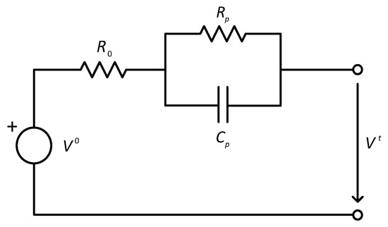
Figure 2.
Thevenin equivalent circuit model for an electric battery.
The variables considered are explained as follows:
- is the Open Circuit Voltage (OCV). During the normal usage of the battery, this quantity cannot be measured, because the load should be zero and a period of relaxation after the last use is needed. These conditions are not normally encountered in a mission. The relationship is a non-linear static map that can be obtained for a battery batch using laboratory tests on samples.
- is the battery terminal voltage. It can be easily measured even during use.
- is the voltage across the polarization capacitor. It cannot be measured. This makes SOC estimation more difficult.
- I is the electrical current entering the battery (negative during discharge). It can be measured during use, typically with less accuracy than voltage.
The parameters of the model are as follows:
- represents the internal resistance of the battery. Its value is state-dependent.
- and are the resistance and capacitance due to polarization in the battery.
- is the nominal capacity of the battery ().
During use, on-line identification can provide estimations for all parameters except . For this task, measurements of and I are needed. The trajectories of and I should have enough excitation [33].
It must be noted that parameters can suffer from fast-acting changes (hours) due to external factors such as temperature as well as slow-acting changes (days) due to the ageing of the battery [34].
The battery model can be obtained from the diagram of Figure 2 as follows:
where is the time-constant due to polarization.
2.1. Identification of Model Parameters
For a battery batch, values and the relationship can be obtained from laboratory tests in which charge/discharge periods are issued with long intermissions to allow for de-polarization [35]. In this way, a relationship such as the one depicted in Figure 3 is obtained. From this experimental curve, the values can be obtained. It should be kept in mind that this curve is subject to uncertainties not only from its experimental nature but also from deviations of particular batteries from sample averages. The particular curve shown in Figure 3 is for a Lithium Phosphate (LiFePO4) commercial battery.
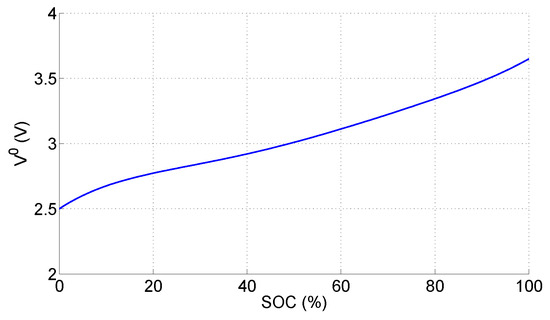
Figure 3.
Experimental values for of a LiFePO4 battery.
The rest of the model parameters can be obtained for particular batteries during normal use using identification techniques [33]. In this way, values for , , , and are obtained from measurements of I and . These parameters can change due to external factors such as temperature and also due to battery ageing. Periodic re-identifications can be performed to account for such drift in values. The persistence of excitation needed by the identification procedure can be obtained by injecting small signals of high frequency or just by letting the normal use provide changes in I and .
2.2. SOC Estimation
The proposal of this work allows for the assessment of SOC estimation techniques of many kinds. A short review of the simpler ones is presented for concretion.
From the experimental curve , we obtain
which constitutes a SOC estimation based entirely on the observed Open Circuit Voltage. This voltage should be measured for and after a period of de-polarization. This is not easy to obtain during the normal use of the battery onboard the aircraft on a mission.
The usual Coulomb counting method provides an estimation that depends solely on current measurements I:
A combination of the two previous methods is obtained using the Kalman filter with the discrete-time model arising from the equivalent circuit. The derivatives of certain variables with respect to the SOC are also needed [35]. To this end, Equations (1) and (2) are subjected to linearization. Also, the steady state term must be considered by extending the state vector to ; the output measurement vector is and the state space equations as follows.
where , and matrices , , and are given as:
Variable represents the derivative , and is a coefficient computed as
The KF estimation of the state uses the usual equations:
where the time indices have been dropped for readability. The state covariance matrix Q and sensor covariance matrix R have been used in the previous equations. KF model matrices A, B, C and D are assumed to correspond to those of the model , , and , respectively.
For the assessment of the SOC estimator, the estimated values should be compared with real values. However, the real must undergo elaborate testing in a laboratory, so this comparison of vs. is seldom encountered in the literature. Instead, the battery terminal voltage is used as a measure of how well the estimation and the model represent the measurements. As a result, what is really assessed is the ability of the procedure to predict .
This observation points out that terminal voltage error is not a precise evaluation metric for SOC estimation. The ultimate reason for this is clear: the relation of voltage with SOC is neither static nor simple (see Equations (1)–(4) representing a dynamic and non-linear system). As a result, terminal voltage is a proxy. As with any proxy, its usefulness is not infinite, but limited, as will be shown in the experiments later on.
The proposal aims to produce a posteriori accurate estimations of SOC for assessment purposes.
3. Reverse-Time Kalman Filter
The assessment of KF SOC estimation is hindered by the fact that the real values of SOC are seldom known. The proposal makes use of the fact that, after a mission, the battery is completely charged. At this point, the SOC is known to be . The proposal relies on using a time-reversed KF to obtain re-estimations of SOC for the times . Figure 4 illustrates the idea of the proposed method. The curve represents the initial estimations obtained by any means (the KF, for instance) starting with an uncertain initial value . The real SOC is unknown, but it has been included in the diagram to make the explanations easier to follow. Now, during the period going from to , the battery is subject to discharging in a normal mission. It can be seen that goes down with time. From , a charging procedure is carried out. This concludes at time when charging is completed. At this point, the uncertainty about SOC is zero. Then, going back in time, it is possible to re-estimate the SOC (represented by the line ). The re-estimations can go back to any time, including the interesting period . The discrepancy between direct KF and reverse-time KF estimations are mostly due to the uncertainty in . In this way, the ability of the direct KF method to deal with uncertain initial states is assessed.
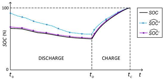
Figure 4.
SOC re-estimation example.
With this idea in mind, the reverse-time KF (RTKF) is developed by using the following reverse-time model:
where , , and . This new model can be used with the usual KF Equations (11)–(15), taking , , and . Also, the temporal indices must be reversed.
4. Experimental Study
The RTKF method will be put to the test in a series of experiments where the KF is used online during a mission starting with an uncertain SOC. The laboratory equipment is shown in Figure 1. The elements of the experimental setup are presented in Figure 5 and commented below.
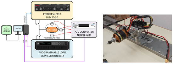
Figure 5.
Diagram of the experimental setup for data gathering (left) and photograph of the rig for testing battery usage (right).
- An electronic load where the battery power is dissipated, emulating the discharge. The load is programmable, so that discharging profiles can be setup to match those encountered during an aircraft mission.
- Voltage, current, and temperature sensors.
- Analog-to-digital conversion system with a maximum of 16 bits.
- Scada system based on a desktop computer for data gathering.
- A programmable voltage source to carry out battery charge after .
- An electrical load for battery testing.
The system allows for the selection of the sampling period and the precision of measurements by controlling the number of bits in the (A/D) conversions.
Test Suite
A set of tests is performed in the experimental setup to showcase the proposal. The test combines two discharge profiles—a charging profile, and various options for the uncertainty of the initial estimation . The objective involves showing the capabilities of the usual KF SOC estimator by comparing the normal estimations with the a posteriori ones obtained by the RTKF. Figure 6 presents the current and voltage for trajectory T1, whereas Figure 7 is for T2. Table 1 shows the parameters and options used on each experiment of the test suite. The test is identified by a letter (A to F) in the first column. The initial estimation of SOC used by the KF is indicated in the second column. The sampling time is set to the value indicated in the third column. The discharge trajectory is shown in the fourth column. Finally, the a posteriori estimation of SOC for is presented in the last column. This last figure, , is more robust in the face of initial estimate uncertainties, unlike the standard KF estimation. This is also shown in Figure 8. Now, the actual conditions for the experiments are known to some degree thanks to the use of a controlled laboratory setup. In particular, for trajectory T1, the initial charge is (%), whereas for trajectory T2 it is (%). Please note that, in a practical situation, the initial estimation can be subject to large uncertainties. Regarding the sampling period, the values of Table 1 are within the range feasible for the on-board system of a small aircraft.
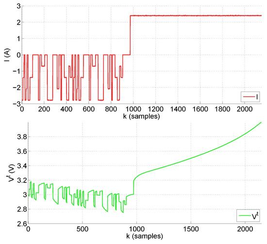
Figure 6.
Current (top graph) and terminal voltage (bottom graph) for trajectory T1 used in tests A, B, C and D.
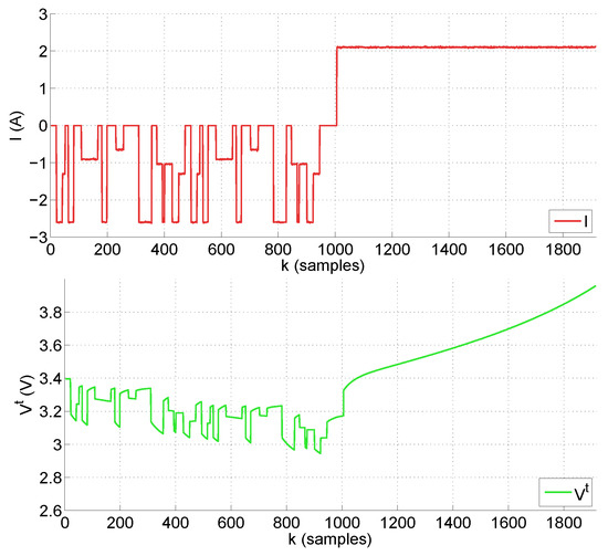
Figure 7.
Current (top graph) and terminal voltage (bottom graph) for trajectory T2 used in tests E and F.

Table 1.
Parameters and options of the experiment suite.
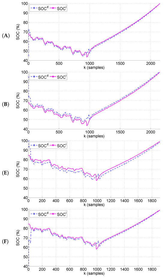
Figure 8.
SOC estimation for standard KF and for RTKF for cases A, B, E and F.
The results shown in Figure 8 show that the standard KF is able to correct the estimations in the face of uncertainty about . This is more apparent for the few initial samples of each tests, where changes abruptly from the provided initial estimation to a value more similar to that obtained with the RTKF. This is due to the use of the battery model and specially the measurement. However, as the mission advances, the differences in SOC between the direct and the reverse-time estimations do not converge to zero. In some cases, such as (B) and (E), a sort of constant displacement is observed. This is due to the fact that the KF is basically a correction of the Coulomb counting method based on measurements. For such a correction, the OCV curve of Figure 3 is used. The uncertainty in said curve, due to experimental effect and batch dispersion, makes the correction biased. This is a finding of this paper that does not have correspondence in previous work, where SOC estimation is validated by . In all cases considered, the error in terminal voltage takes really minuscule values on the order of mili-Volts. This clearly indicate that assessment of SOC estimation schemes should not be based on alone.
The effect of sampling period on the scheme is interesting. In the experiments, a factor of 4 is introduced from cases A and B to cases C and D. The SOC re-estimation with (s) results in 68.2 (%) for case (A), whereas for the re-estimation yields a value of 68.5 (%) for case (C). A similar conclusion is obtained for case (B) compared with case (D). This is an unanticipated result, since one would fear a larger degradation in the estimations due to a much larger sampling period. This is of importance for small aircraft equipment having to resort to larger sampling periods.
It is worth noting that the values used for are in the range of what typical hardware can attain. For other ranges and/or applications, the conclusion might not be the same. In this case, and due to the restrictions of weight in small aircrafts, this result can be used to optimize hardware and/or software.
Finally, the influence of the A/D accuracy (in terms of conversion bits) is also surprisingly small. Going from 16 bits to just 12 bits degrades the estimations by 0.01 (%), which is small enough not to be considered for this kind of application.
Again, this observation can be used by hardware designers to produce cost-effective hardware components, ensuring performance.
5. Discussion
The results show that uncertainties, due to the lack of knowledge about the initial SOC, can be alleviated by standard Kalman estimation only up to a certain degree. The re-estimation based on the proposal shows that the uncertainty in SOC is not completely eliminated. Standard Kalman estimation is based on the used terminal voltage. One might argue then that terminal voltage is not a precise indicator for SOC estimation assessment.
One might think that improved algorithm design or the introduction of additional information could better handle initial SOC uncertainties. However, improved algorithms still rely on terminal voltage error [17,18]. Regarding additional information, there are some works dealing with this, but so far they require additional hardware that makes it unsuitable for some applications, such as small aircrafts [22].
The results obtained in terms of SOC estimation degradation with an increased sampling period and reduced A/D are also interesting for future research on hardware/software optimized for weight and energy consumption.
6. Conclusions
The reverse time Kalman estimator has provided a tool for assessing techniques used for an online estimation of SOC in batteries. Although the paper is focused on the application in small unmanned aircraft, the technique can be applied to other systems. As a main conclusion, the analysis has shown that terminal voltage has limitations as a proxy for SOC.
The technique also allows for an assessment of the effect of other factors, such as the sampling time used for data gathering and A/D accuracy.
From the insight gained by the paper, future research directions should include other factors that might be present in UAV missions. Also, the possibility of optimizing the measurement hardware and software can be concluded from the results.
Author Contributions
Conceptualization, S.E.; Data curation, A.P.V.-L.; Funding acquisition, M.R.A.; Investigation, A.P.V.-L. and M.G.S.; Methodology, M.R.A.; Project administration, M.R.A.; Resources, A.P.V.-L. and M.G.S.; Software, M.R.A. and M.G.S.; Supervision, S.E.; Validation, M.R.A.; Visualization, M.G.S.; Writing—original draft, M.R.A., A.P.V.-L., M.G.S. and S.E. All authors have read and agreed to the published version of the manuscript.
Funding
This research is part of Proyecto -I+D+i/PID2021- 125189OB- I00- financiado por MICIU/AEI/10.13039/501100011033 y por FEDER, UE.
Data Availability Statement
The raw data supporting the conclusions of this article will be made available by the authors on request.
Conflicts of Interest
The authors declare no conflicts of interest. The funders had no role in the design of the study; in the collection, analyses, or interpretation of data; in the writing of the manuscript; or in the decision to publish the results.
Abbreviations
The following abbreviations are used in this manuscript:
| A/D | Analog to Digital conversion |
| KF | Kalman Filter |
| LiFePO4 | Lithium Iron Phosphate |
| OCV | Open Circuit Voltage |
| RC | Resistive-Capacitive |
| RTKF | Reverse-Time Kalman Filter |
| SAR | Search And Rescue |
| SOC | State Of Charge |
| UAV | Unmanned Aerial Vehicle |
References
- Airsight. Drone Capabilities–Endurance and Range. Available online: https://www.airsight.com (accessed on 7 August 2024).
- Mukherjee, S.; Chowdhury, K. State of charge estimation techniques for battery management system used in electric vehicles: A review. Energy Syst. 2023, 1–44. [Google Scholar] [CrossRef]
- Dini, P.; Colicelli, A.; Saponara, S. Review on Modeling and SOC/SOH Estimation of Batteries for Automotive Applications. Batteries 2024, 10, 34. [Google Scholar] [CrossRef]
- Rivera-Barrera, J.; Muñoz-Galeano, N.; Sarmiento-Maldonado, H. SoC Estimation for Lithium-ion Batteries: Review and Future Challenges. Electronics 2017, 6, 102. [Google Scholar] [CrossRef]
- Liu, X.; Gao, Y.; Marma, K.; Miao, Y.; Liu, L. Advances in the Study of Techniques to Determine the Lithium-Ion Battery’s State of Charge. Energies 2024, 17, 1643. [Google Scholar] [CrossRef]
- Kolluri, S.; Aduru, S.V.; Pathak, M.; Braatz, R.D.; Subramanian, V.R. Real-time nonlinear model predictive control (NMPC) strategies using physics-based models for advanced lithium-ion battery management system (BMS). J. Electrochem. Soc. 2020, 167, 063505. [Google Scholar] [CrossRef]
- Agarwal, V.; Uthaichana, K.; DeCarlo, R.A.; Tsoukalas, L.H. Development and validation of a battery model useful for discharging and charging power control and lifetime estimation. IEEE Trans. Energy Convers. 2010, 25, 821–835. [Google Scholar] [CrossRef]
- Durán, M.J.; Barrero, F.; Toral, S.; Arahal, M.; Prieto, J. Improved techniques of restrained search predictive control for multiphase drives. In Proceedings of the 2009 IEEE International Electric Machines and Drives Conference, Miami, FL, USA, 3–6 May 2009; pp. 239–244. [Google Scholar]
- Kumar, R.R.; Bharatiraja, C.; Udhayakumar, K.; Devakirubakaran, S.; Sekar, S.; Mihet-Popa, L. Advances in batteries, battery modeling, battery management system, battery thermal management, SOC, SOH, and charge/discharge characteristics in EV applications. IEEE Access 2023, 11, 105761–105809. [Google Scholar] [CrossRef]
- Gómez, F.; Yebra, L.; Giménez, A.; Torres-Moreno, J. Modelling of batteries for application in light electric urban vehicles. Rev. Iberoam. Autom. Inform. Ind. 2019, 16, 459–466. [Google Scholar] [CrossRef]
- Martí-Florences, M.; Cecilia, A.; Costa-Castelló, R. Modelling and Estimation in Lithium-Ion Batteries: A Literature Review. Energies 2023, 16, 6846. [Google Scholar] [CrossRef]
- Piller, S.; Perrin, M.; Jossen, A. Methods for state-of-charge determination and their applications. J. Power Sources 2001, 96, 113–120. [Google Scholar] [CrossRef]
- Coleman, M.; Lee, C.K.; Zhu, C.; Hurley, W.G. State-of-charge determination from EMF voltage estimation: Using impedance, terminal voltage, and current for lead-acid and lithium-ion batteries. IEEE Trans. Ind. Electron. 2007, 54, 2550–2557. [Google Scholar] [CrossRef]
- Sun, J.; Tang, Y.; Ye, J.; Jiang, T.; Chen, S.; Qiu, S. A novel capacity and initial discharge electric quantity estimation method for LiFePO4 battery pack based on OCV curve partial reconstruction. Energy 2022, 243, 122882. [Google Scholar] [CrossRef]
- Wang, Y.; Tian, J.; Sun, Z.; Wang, L.; Xu, R.; Li, M.; Chen, Z. A comprehensive review of battery modeling and state estimation approaches for advanced battery management systems. Renew. Sustain. Energy Rev. 2020, 131, 110015. [Google Scholar] [CrossRef]
- Yu, Q.; Dai, L.; Xiong, R.; Chen, Z.; Zhang, X.; Shen, W. Current sensor fault diagnosis method based on an improved equivalent circuit battery model. Appl. Energy 2022, 310, 118588. [Google Scholar] [CrossRef]
- Cui, Z.; Wang, L.; Li, Q.; Wang, K. A comprehensive review on the state of charge estimation for lithium-ion battery based on neural network. Int. J. Energy Res. 2022, 46, 5423–5440. [Google Scholar] [CrossRef]
- Ghaeminezhad, N.; Ouyang, Q.; Wei, J.; Xue, Y.; Wang, Z. Review on state of charge estimation techniques of lithium-ion batteries: A control-oriented approach. J. Energy Storage 2023, 72, 108707. [Google Scholar] [CrossRef]
- Arahal, M.R.; Barrero, F.; Satué, M.G.; Bermúdez, M. Fast Finite-State Predictive Current Control of Electric Drives. IEEE Access 2023, 11, 12821–12828. [Google Scholar] [CrossRef]
- Hidalgo, H.; Huerta, H. Sliding mode control for an electrical vehicle with differential speed. Rev. Iberoam. Autom. Inform. Ind. 2021, 18, 115–124. [Google Scholar]
- Colodro, F.; Mora, J.L.; Barrero, F.; Arahal, M.R.; Martinez-Heredia, J.M. Analysis and simulation of a novel speed estimation method based on oversampling and noise shaping techniques. Results Eng. 2024, 21, 101670. [Google Scholar] [CrossRef]
- Salem, K.A.; Palaia, G.; Quarta, A.A. Review of hybrid-electric aircraft technologies and designs: Critical analysis and novel solutions. Prog. Aerosp. Sci. 2023, 141, 100924. [Google Scholar] [CrossRef]
- Altun, Y.E.; Kutlar, O.A. Energy Management Systems’ Modeling and Optimization in Hybrid Electric Vehicles. Energies 2024, 17, 1696. [Google Scholar] [CrossRef]
- Stoica, C.; Arahal, M.R.; Rivera, D.E.; Rodriguez-Ayerbe, P.; Dumur, D. Application of robustified model predictive control to a production-inventory system. In Proceedings of the 48th IEEE Conference on Decision and Control (CDC) and 28th Chinese Control Conference, Shanghai, China, 15–18 December 2009; pp. 3993–3998. [Google Scholar]
- Bermúdez, M.; Martín, C.; González-Prieto, I.; Durán, M.J.; Arahal, M.R.; Barrero, F. Predictive current control in electrical drives: An illustrated review with case examples using a five-phase induction motor drive with distributed windings. IET Electr. Power Appl. 2020, 14, 1291–1310. [Google Scholar] [CrossRef]
- Zhang, Q.; Ikram, M.; Xu, K. Online Optimization of Vehicle-to-Grid Scheduling to Mitigate Battery Aging. Energies 2024, 17, 1681. [Google Scholar] [CrossRef]
- Martínez-Vera, E.; Rosado-Muñoz, A.; Bañuelos-Sánchez, P. Lithium-ion Battery State of Charge Estimation with Neural Networks and FPGA-in-the-loop validation. Rev. Iberoam. Autom. Inform. Ind. 2024, 21, 243–251. [Google Scholar] [CrossRef]
- Clemente, A.; Montiel, M.; Barreras, F.; Lozano, A.; Costa-Castelló, R. Experimental validation of a vanadium redox flow battery model for state of charge and state of health estimation. Electrochim. Acta 2023, 449, 142117. [Google Scholar] [CrossRef]
- Soto-Marchena, D.; Barrero, F.; Colodro, F.; Arahal, M.R.; Mora, J.L. On-Site Calibration of an Electric Drive: A Case Study Using a Multiphase System. Sensors 2023, 23, 7317. [Google Scholar] [CrossRef]
- Eltoumi, F.; Badji, A.; Becherif, M.; Ramadan, H. Experimental identification using equivalent circuit model for lithium-ion battery. Int. J. Emerg. Electr. Power Syst. 2018, 19, 20170210. [Google Scholar] [CrossRef]
- Tian, N.; Fang, H.; Chen, J.; Wang, Y. Nonlinear double-capacitor model for rechargeable batteries: Modeling, identification, and validation. IEEE Trans. Control Syst. Technol. 2020, 29, 370–384. [Google Scholar] [CrossRef]
- Zhou, W.; Zheng, Y.; Pan, Z.; Lu, Q. Review on the battery model and SOC estimation method. Processes 2021, 9, 1685. [Google Scholar] [CrossRef]
- Arahal, M.R.; Berenguel, M.; Rodríguez, F. Técnicas de Predicción con Aplicaciones en Ingeniería; Universidad de Sevilla: Seville, Spain, 2006. [Google Scholar]
- Puleston, T.; Cecilia, A.; Costa-Castelló, R.; Serra, M. Vanadium redox flow batteries real-time State of Charge and State of Health estimation under electrolyte imbalance condition. J. Energy Storage 2023, 68, 107666. [Google Scholar] [CrossRef]
- How, D.N.; Hannan, M.; Lipu, M.H.; Ker, P.J. State of charge estimation for lithium-ion batteries using model-based and data-driven methods: A review. IEEE Access 2019, 7, 136116–136136. [Google Scholar] [CrossRef]
Disclaimer/Publisher’s Note: The statements, opinions and data contained in all publications are solely those of the individual author(s) and contributor(s) and not of MDPI and/or the editor(s). MDPI and/or the editor(s) disclaim responsibility for any injury to people or property resulting from any ideas, methods, instructions or products referred to in the content. |
© 2024 by the authors. Licensee MDPI, Basel, Switzerland. This article is an open access article distributed under the terms and conditions of the Creative Commons Attribution (CC BY) license (https://creativecommons.org/licenses/by/4.0/).