Abstract
When traditional grid-forming converters directly participate in the grid-connected operation of the power grid, due to the lack of a pre-synchronization control system, the voltage amplitude and initial phase on both sides of the grid-connected point will deviate, resulting in voltage and current distortion during grid-connected mode. An active support phase-locked loop free pre-synchronization control strategy based on the third-order model of a synchronous generator is proposed to address the grid-connected problem of the grid-forming converter mentioned above. First, a model of active support control with frequency integral feedback at small signal levels was constructed. The root locus method was employed to examine how system parameters affect the stability of the active support control system. Second, by adding phase pre-synchronization controllers and amplitude pre-synchronization controllers to the active frequency loop and excitation voltage loop of the third-order model, it was ensured that the frequency, phase, and voltage amplitude of the unit are consistent with the power grid, achieving a fast and smooth grid-connected mode of the unit. Finally, by using a DC source to simulate all types of new energy power generation equipment, the active support pre-synchronization control system based on the three-order model of synchronous generator is built in the MATLAB/Simulink simulation environment, and the accuracy and effectiveness of the control strategy in this paper is verified.
1. Introduction
With the rapid development of the economy, the large-scale development and utilization of renewable energy, and the access of a large number of renewable energy stations and cross-regional DC transmission, the inertia of the power grid is missing, resulting in a decrease in the stability of the grid-connected point voltage. For the power system with a high proportion of renewable energy grid-connection, due to its insufficient voltage and frequency support, the anti-interference ability of the power system and the recovery ability after failure are seriously deteriorated. Therefore, how to improve the support ability and recovery ability of the high proportion of a renewable energy power grid has become an important issue that needs attention [1,2,3,4].
Zhuo et al. proposed a control strategy based on the Virtual Synchronous Generator (VSG) that mimics the inertia characteristics of synchronous generators, thereby addressing the issues of low inertia and lack of damping in power electronic devices [5]. However, this strategy may produce significant voltage and current impacts when the system transitions from off-grid mode to grid-connected mode. Huang et al. investigated the power coupling mechanism in medium- and low-voltage grids based on the VSG model and introduced the concept of a phase angle pre-synchronization unit to accelerate the system’s grid-connection speed [6]. However, this study did not consider the impact of amplitude, which may affect the stability of grid connection. Cheng et al. proposed an adaptive virtual impedance control strategy that effectively enhanced the unit’s ability to provide reactive power in the power system and achieved stable operation under low-voltage conditions [7]. Despite this effect, the research on grid-connection strategies was still insufficient.
Through the aforementioned studies, it is evident that while existing control strategies improved the stability and reliability of power systems to some extent, they still have limitations. For instance, most studies are based on simplified models and assumptions, lacking consideration of the actual dynamic characteristics of the power grid. Moreover, existing control strategies are still insufficient in handling voltage and current impacts at the grid connection point.
In order to ensure the stable and safe operation of the power grid, the power electronic equipment in the power system needs to have a certain active support ability to play a certain supporting role in the frequency. The traditional virtual synchronous generator (VSG) control draws on the advantages of synchronous generators, to solve the problem of low inertia and no damping of power electronic equipment, and then improve the compatibility between power electronic equipment and the power grid. However, when the system is switched from off-grid to grid-connected after the system fault is removed, the problem of large voltage and current impact may occur.
In order to solve this problem, reference [8] studied the mechanism of power coupling in medium- and low-voltage power grids based on the VSG model. A concept of phase angle pre-synchronization unit is proposed to speed up the grid-connected speed of the system without considering the influence of amplitude. In reference [9], by adding a pre-synchronization controller to the VSG-controlled doubly fed wind turbine and introducing the virtual impedance into the reactive voltage loop, the fast and smooth grid-connected of the unit is realized. The purpose of introducing the transient damping link in Reference [10] is to simulate the transient characteristics of the synchronous generator, i.e., in the transient process, the synchronous generator will absorb the energy difference between the grid and the load through the damping winding to achieve a smooth transition. In this paper, we found that by adding a frequency feedback link to the control, the transient response of the synchronous generator can be better simulated, and the dynamic performance of the system can be improved. According to the low-frequency nonlinear behavior of the phase-locked loop under different impedance conditions, Reference [11] formed an evaluation framework for the influence of a large penetration level of distributed generators, weak grid, microgrid, and large reactive power consumption on the frequency stability of the phase-locked loop. Reference [12] directly used a linear proportional integral controller to act on the synchronization loop, which may lead to a decline in operational stability. In this paper, the number of two-phase stationary coordinate systems is used for synchronization to maintain system stability. Reference [13] constructed a three-order model of the synchronous generator, introduced adaptive virtual impedance, effectively improved the ability of the unit to provide reactive power in the power system, and realized the stable operation of the unit under low-voltage conditions and the limitation of short-circuit current. However, the research on the grid-connected strategy after off-grid is still insufficient.
In order to make up for the shortcomings of the above problems, this paper proposes a pre-synchronization control strategy based on the active support control of the third-order model of synchronous generator. The phase pre-synchronization controller and the amplitude pre-synchronization controller were added to the active-frequency loop and the excitation voltage loop in the third-order model. The effectiveness of the proposed switching control strategy is verified by the simulation model.
The structure of this paper is as follows: Section 1 (Introduction): introduces the research background, existing problems, and the necessity of the research; Section 2 (Literature review): reviews the research progress and existing problems in related fields; Section 3 (Control strategy and mathematical model): the control strategy and mathematical model proposed by us are introduced in detail. Section 4 (simulation verification): simulation experiments and the result analysis in an MATLAB/Simulink 2023b environment are shown.
2. Mathematical Model and Control Strategy of Active Support
The pre-synchronization control structure and model based on active support are shown in Figure 1. When the PCC switch S1 is closed, the inverter operates in grid-connected mode. When the switch S1 is disconnected, the inverter operates in off-grid mode.
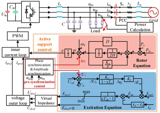
Figure 1.
A pre-synchronization control frame model based on active support.
2.1. Rotor Motion Equations
The motion equations of the traditional generator and prime mover are as follows:
In the formula, J is the total rotational inertia of the generator and the steam turbine, ωm is the rotor angular velocity of the generator, Tm is the mechanical torque, and Te is the electromagnetic torque.
The virtual inertia constant H under the per-unit value is used to normalize, VA represents the kinetic energy reference value, and ω0m represents the rated angular velocity. Then, the virtual inertia constant is as follows:
Substituting Formula (2) into Formula (1), we can obtain the following:
Among them, VA/ω0m m is the reference value of torque. Due to the large inertia of the generator set, when the mechanical angular velocity of the unit changes, the degree of change is very small. Therefore, it is approximately considered that the per unit value of torque is equal to the per unit value of power. Simplification can be obtained by the following:
In the formula, ω is the angular velocity of the generator, Pm is the mechanical power, and Pe is the electromagnetic power.
If δ is the power angle of the generator, which reflects the angular position of the rotor and derives it from time, according to the above derivation and considering the damping torque component, the rotor motion equation can be expressed as the following:
In the formula, D is the damping coefficient, Δω is the deviation between the rated speed and the actual speed, and δ is the power angle of the generator.
Figure 2 shows the active power frequency control link corresponding to the rotor motion equation.

Figure 2.
Active frequency control loop.
2.2. Excitation Controller
The transient voltage equation is introduced into the excitation controller of the synchronous generator to form a voltage regulation control link that actively supports the pre-synchronization control. The formula is as follows:
In the formula: U0 and Uref are the actual value and reference value of the grid-connected point voltage of the unit, Ke is the proportional coefficient, Te is the integral constant, and Δuf is the excitation voltage deviation.
The forced no-load electromotive force Eqe and excitation voltage uf is a linear relationship that is depicted in the formula as follows:
In the formula: xad is the reactance of the direct axis armature reaction winding, rf excitation winding reactance, and Kf is the excitation proportional coefficient. Figure 3 is the excitation voltage regulation control block diagram corresponding to the transient voltage equation.

Figure 3.
Excitation voltage regulation control block diagram.
The traditional reactive power–voltage droop control method is to control the voltage by adjusting the reactive power of the generator set so that the output voltage of the generator set and the network voltage remain stable. However, this method has the problem of an indirect voltage regulation process, which will lead to the instability of transient voltage. To address this challenge, we utilized the voltage deviation at the grid-connected point of the system unit as the reference signal for the excitation controller’s voltage regulation. This approach eliminates the need for an indirect voltage regulation process, thereby enhancing the transient voltage stability of the power system [14].
In order to establish the third-order model of the synchronous generator in this paper, the change in electromotive force in practice should be considered on the basis of the above. Therefore, the excitation circuit equation of undamped winding generator is as follows:
In the formula: Td0′ is the time constant of the excitation winding of the synchronous generator, Eq is the quadrature axis electromotive force, Eq′ is the transient electromotive force, Eqe is the forced no-load electromotive force, id is the direct axis current component, xd is the direct axis synchronous reactance, and xd′ is the direct axis transient reactance.
Substituting Formula (9) into Formula (8), we can obtain the following:
The relationship between the transient electromotive force change unit and the grid-connected point voltage change isas follows:
At the same time, by integrating the excitation controller and the transient voltage controller, the voltage regulation control system can more accurately perceive and respond to the dynamic changes in the power grid and achieve more stable voltage control in the transient process. Figure 4 shows the excitation circuit control block diagram.

Figure 4.
Excitation circuit control loop.
As depicted in Figure 4, to achieve independent control over active and reactive power, we disregarded the transient components within the dq coordinate system. The virtual impedance control is then applied, as detailed in the subsequent formula [14]:
In conclusion, the active support control formula, grounded on the third-order model of the synchronous generator, is presented in Formula (13) [15].
3. Analysis of Active Support Grid-Connected Mode
3.1. Off-Grid Mode Frequency Regulation
In Figure 5, the active power-frequency droop characteristics of active support control are shown. In the case of off-gridding, when the active power of the load does not match the output active power command of the control unit, the corresponding frequency of the system will also deviate from the rated value, which will adversely affect the unit.
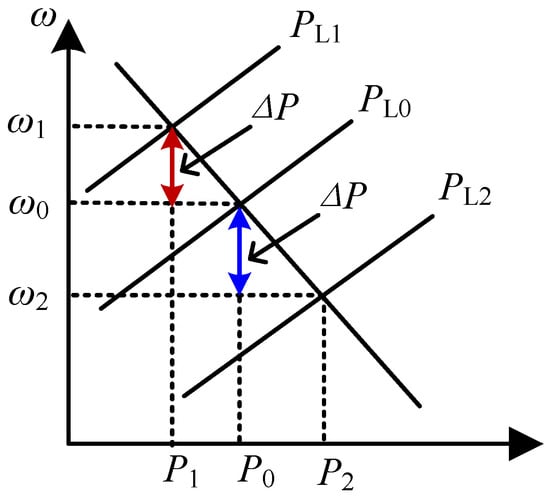
Figure 5.
Active power and frequency droop characteristics.
In general, the output frequency of the inverter will have an error with the frequency of the grid end. This error will accumulate over time and eventually be converted into a phase error. When the microgrid is switched from off-grid to grid-connected, this phase error may cause the voltage at both ends of the switch to be out of sync, which in turn causes a large inrush current, making the grid-connected step unable to be successfully completed. If the grid is forced to be grid-connected, the distortion of the voltage and current will seriously affect the power quality of the system. In order to solve the above problems, an integral feedback link is added to the traditional power angle control link, which can reduce the difference between the actual frequency and the rated frequency in the off-grid mode, thereby improving the stability and security of the power system and reducing the frequency fluctuation and voltage and the current impact during grid-connected mode.
As shown in Figure 6, the active power compensation link is added to the active power-frequency loop, and the control equation is as follows:
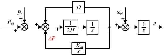
Figure 6.
Block diagram of active power control with frequency modulation characteristics.
Substitute into formula:
From the above, it can be seen that the active power compensation compensates for the load active power fluctuation. Figure 7 shows the frequency response when the frequency modulation integral parameter K takes different values in the off-grid mode.
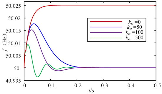
Figure 7.
Frequency response diagrams under different frequency modulation integral parameters.
It can be seen from Figure 7 that when Kω = 0, i.e., without frequency feedback, the frequency response in off-grid mode will remain at a non-rated value, which will adversely affect power equipment in the long run. When the frequency feedback regulation is introduced, the system frequency returns to the rated value. Under the condition that other parameters remain unchanged, as Kω increases, the initial peak of the system frequency decreases and the frequency fluctuation increases. Therefore, the value of Kω should be reasonably selected.
3.2. Small Signal Analysis of Active Support with Integral Link
The mathematical model of the active support VSC adopts the standard third-order model of the synchronous machine in the previous article. The design of the exciter simulates the design method of the excitation controller of the synchronous machine. It is assumed that the governor does not participate in the working mechanical power, ignoring the distributed capacitance of the line and the line loss. The voltage of the active support VSC grid-connected mode is the infinite system voltage U = Ug ∠ 0°, and the rated capacity and rated voltage are as follows: SB = 20 kVA and UB = 311 V. The expression of electromagnetic power Pe is as follows:
Since the excitation voltage Ef. and the forced no-load electromotive force Eqe are in a linear proportional relationship, the proportional coefficient is xad/rf. If the reference values of the excitation voltage Ef and the forced no-load electromotive force Eqe are set to show the same proportional relationship, the excitation voltage and the forced no-load electromotive force are equal. Therefore, the linearization of Equations (13) and (17) at the steady-state operating point of the system can be obtained by the following:
In the formula: the amount of subscript 0 represents the value of the corresponding variable at the static operating point.
The terminal voltage of the inverter is expressed in the x–y coordinate system:
The real part and the imaginary part of the inverter terminal voltage Ut can be obtained by the following:
The transformation matrix from the x–y stationary coordinate system to the d–q axis coordinate system is as follows:
Substituting Equation (22) into Equation (21), through the transformation from the x–y to the d–q coordinate system, we can obtain the following:
The mathematical model of the inverter terminal voltage in the d–q coordinate system is as follows:
The simultaneous Equations (23) and (24) are available:
Let (25) and (26) be incremental, then the incremental equation is the following:
The effective value of the inverter terminal voltage Ut is as follows:
The corresponding incremental form is as follows:
Because the unit values of Ef and Eqe are equal, the transfer function of excitation system can be rewritten as the following:
The incremental equation of the transfer function of the excitation system can be reduced to the following:
The simultaneous Equations (30) and (32) are available:
Based on the above derivation process, ΔPe ΔEq, and ΔUt can be written in the form of ΔEq′ and Δδ:
where K1~K6 are, respectively, as follows:
By combining the parameters of the linearized model of the above system and eliminating the intermediate algebraic variables, the system state equation shown in Equation (40) can be obtained.
The system parameters of the active support VSC grid-connected structure are shown in Table 1.

Table 1.
Actives support VSC grid-connected structural system parameters.
The proportional gain parameter of the exciter is Ke = 50, the integral link parameter is Te = 0.05, the frequency feedback integral Kω = 100, the steady-state operating point of the system Pt0 = 0.5, the voltage value of the infinite power grid is 1, and the voltage value of the active support VSC grid-connected end is 1.05. The above data are all under the per unit value, and the initial power angle of the system is calculated to be 29°.
The state equation of the system is as follows:
The above formula can be written as . The corresponding characteristic equation is equal to 0:
Among them, the matrix I is a fourth-order unit matrix, and the corresponding determinant is as follows:
The above determinant is zero, and the corresponding characteristic equation can be obtained. It can be seen from the above equation that the distribution of the characteristic roots is mainly affected by the virtual inertia coefficient H and the damping coefficient D. Different virtual inertia coefficients H and damping coefficients D correspond to different characteristic roots. The distribution of characteristic roots under different D or H parameters is analyzed by combining the trajectory distribution diagram.
Figure 8 shows the characteristic root locus of the D invariant and H variable. When the damping D is 100, and the inertia H changes from 1 to 20, S1, S2 and S3, S4 are two pairs of main eigenvalues. It can be seen from Figure 8 that when the virtual inertia H changes, S3 and S4 are negative real roots, and the characteristic root changes are not significant. The eigenvalues of S1 and S2 change with the virtual inertia H, and the eigenvalues change significantly. In Figure 8, H increases gradually along the direction of the arrow. The characteristic roots S1 and S2 gradually extend to the imaginary axis due to the gradual increase in inertia H, and the stability of the control system gradually decreases.
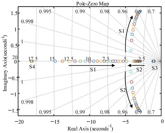
Figure 8.
D unchanged, H variation characteristic root locus analysis.
It can be seen from Figure 9 that H is constant and D changes the characteristic root trajectory. When the inertia H = 2, when the damping D changes from 60 to 140, S1, S2 and S3, S4 are two pairs of dominant eigenvalues of the system. It can be seen from Figure 9 that the characteristic roots S3 and S4 are negative real roots, and the characteristic roots do not change significantly with the change in damping D. The damping D gradually increases along the arrow direction, the characteristic roots S1 and S2 gradually extend to the negative real axis, and the stability of the control system is gradually improved.
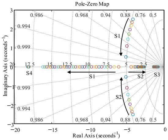
Figure 9.
H unchanged, D variation characteristic root locus analysis.
4. Active Support Pre-Synchronization Grid-Connected Technology
During the grid-connected process of the active support unit, the voltage amplitude and phase of the grid-connected point deviates from the voltage amplitude and phase of the grid. In order to facilitate the analysis, this paper takes the A phase voltage as an example:
In the formula, ωg is the rotation angular velocity of grid voltage, θg is the phase angle of grid voltage, ω0 is the rotation angular velocity of grid-connected point voltage, and θ0 is the phase angle of grid-connected point voltage.
The instantaneous difference ue of the two voltages is as follows:
When the fundamental effective values of the active support unit voltage and the grid voltage are similar, . The instantaneous voltage difference between the two is as follows [12]:
It can be seen that the deviation of frequency and phase leads to the instantaneous voltage difference ue between the active support unit and the power grid, which can reach 2U at most. Even if the phase difference between the two ends of the grid-connected point is very small or 0, due to the phase difference between the voltage and the current, when the circuit breaker is closed at the moment of closing, there will still be an instantaneous current shock. This current shock may not cause serious damage to electrical equipment, but it will cause frequency fluctuation and instability of the system, thus affecting the power quality and stability of the system.
In order to ensure the stability and reliability of the system, it is necessary to detect and correct the voltage amplitude and phase of the system before closing, so as to ensure that the voltage amplitude and phase difference of the system meet the requirements during closing. In this regard, this paper introduces a pre-synchronization control link in the active-frequency loop and the excitation voltage regulation loop. The pre-synchronization control strategy enables the active support unit to achieve fast and smooth voltage synchronization with the grid before reaching grid-connected mode, thereby achieving a smooth grid-connected process. This strategy can improve the reliability of the grid-connected mode, reduce the impact and instability in the process of the grid-connected mode, and help to achieve efficient and sustainable energy of the grid-connected mode.
4.1. Phase Controller
The strategy for pre-synchronization control is crucial for achieving a seamless transition to an off-gridded operation mode. The detailed control sequence is as follows: upon receiving the command to connect to the grid, the controller adopts the grid voltage as its reference. It then continuously adjusts its output to match the voltage magnitude. Once the conditions for grid connection are met, the PCC switch S1 is activated, enabling the controller to swiftly change its operational mode. The concept of pre-synchronization control is depicted in Figure 10.
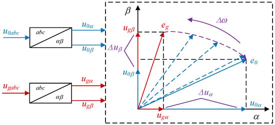
Figure 10.
Pre-synchronization control principle.
Before grid-connected mode, the switch S1 at PCC is in a disconnected state, and the phase amplitude pre-synchronization controller switch S2 is in a disconnected state, i.e., the frequency and phase of the output voltage are not adjusted. When the unit is switched to the pre-synchronization mode, the switch S2 is closed, S1 remains disconnected, and the pre-synchronization controller is started. When the system is synchronized with the grid, the switch S1 is closed, S2 is disconnected, the pre-synchronization controller is out of operation, and the system enters the grid-connected mode.
As shown in Figure 11. The phase synchronization controller adjusts the voltage component difference between the PCC and the grid on the αβ axis to approach 0, and the difference is compensated by the PI regulator to compensate the output frequency of the unit, which can realize the phase synchronization of the voltage at the PCC and the grid voltage. By omitting the phase-locked loop section, the pre-synchronization grid-connected technology of the control strategy is simplified, and the stability and reliability of the system are improved.
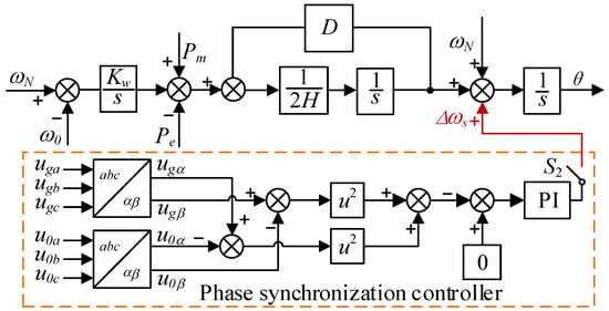
Figure 11.
Phase synchronization controller.
4.2. Amplitude Controller
By adding an amplitude pre-synchronization controller, the voltage amplitude of the power grid and the unit can be monitored, and the difference is input into the excitation controller as a reference signal. The excitation controller adjusts the excitation voltage of the unit according to the difference signal, so that the voltage amplitude of the unit gradually matches the grid to reduce the voltage difference and impulse current when connected to the grid.
The unit sends out the pre-synchronization signal and closes the switch S2, and the amplitude pre-synchronization controller starts to run. In Figure 12, the two-phase static coordinate system is used to calculate the amplitude of the grid-connected point and the grid voltage. Then, the difference between the two is calculated and compensated with the expected error. The compensated signal is fed back to the excitation controller through the PI module to achieve fast tracking of the grid voltage.
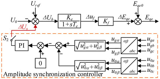
Figure 12.
Amplitude synchronization controller.
In order to ensure that the system current impact is within a reasonable range after the grid-connected signal is issued, a reasonable circuit breaker closing threshold should be selected to ensure that the control system can meet certain conditions and issue a closing signal after the pre-synchronization signal is issued. The closing condition is set as the following:
In the formula, is the speed difference judgment threshold of the system, is the phase difference judgment threshold, and is the voltage difference judgment threshold.
When the pre-synchronization is completed, θ0 = θg, U0 = Ug, Ctrl = 1 sends a closing signal, closes the switch S1 at the PCC, and the power grid returns to normal operation.
5. Simulation Verification
In order to verify the correctness of the active support pre-synchronization control technology, the system is built in the MATLAB/Simulink simulation environment. The local active load is 0.25 p.u., and the reactive load is 0.05 p.u. The simulation results are as follows:
The simulation results without pre-synchronization control are shown in Figure 13, where UP is the voltage amplitude of the grid-connected point, Ugabc and Igabc are the three-phase voltage and current of the grid, respectively, and I0abc is the three-phase current of the grid-connected point. The system sends out a grid-connected signal at 0.5 s and forcibly connects to the grid. As can be seen from Figure 13, the system current mutates at the time of the grid-connected mode, and the overshoot is serious. After 0.058 s, the current returns to normal under the clamping effect of the grid. Current distortion has a great impact on the system, resulting in the system’s default off-grid, which adversely affects the safe operation of the power system.
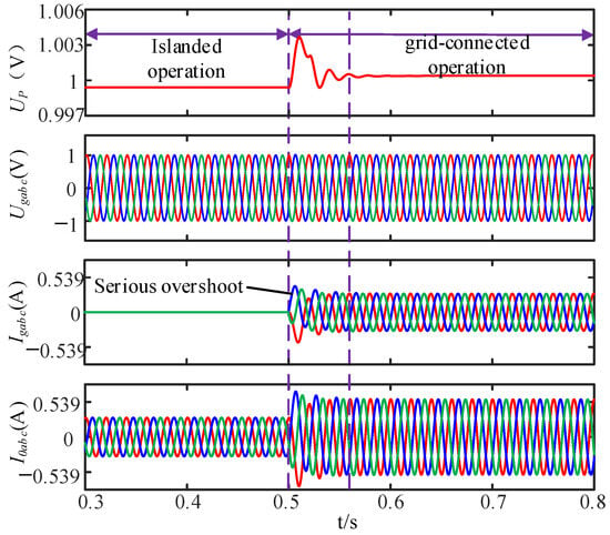
Figure 13.
No synchronous control island to grid voltage and current synchronization process.
In order to verify the accuracy of the pre-synchronization control strategy based on active support control, the simulation results are as follows:
The system emits a pre-synchronization signal at 0.5 s, and the threshold judgment condition is as follows:
Figure 14, Figure 15 and Figure 16 is the simulation waveform in the process of off-grid to grid-connected. The simulation system sends out the grid-connected signal at t = 0.5 s and completes the grid-connected mode at about 0.556 s. From Figure 14, it can be seen that before the grid-connected signal is emitted, the phase of the grid-connected point voltage phase θ0 lags behind the grid voltage phase θg about 10rad. After the pre-synchronization signal is emitted, during the pre-synchronization period, the phase difference value Δθ gradually decreases, reaching the preset threshold at the end of the pre-synchronization, and the grid-connected signal is emitted. After the grid-connected mode is completed, the phase is smooth and synchronized under the drive of the large power grid.
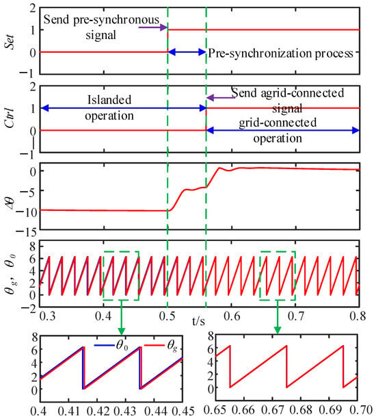
Figure 14.
Phase synchronization process from off-gridding to grid-connected.
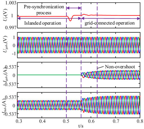
Figure 15.
Voltage and current synchronization process of off-gridding to grid-connected.
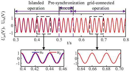
Figure 16.
A-phase voltage comparison.
From Figure 15, it can be seen that the voltage amplitude UP of the grid-connected point changes little during the pre-synchronization period, and the output voltage and current switching of the inverter is smooth, with no jump and no overshoot. It can be seen from Figure 15 that the pre-synchronization control achieves seamless switching compared with the non-additional synchronization control. Figure 16 shows the voltage change at PCC during the seamless switching process. It can be seen that the voltage waveform gradually coincides after pre-synchronization, the grid-connected mode is completed after 0.556 s, and the voltage waveform completely coincides.
In the simulation process, the circuit breaker S1 in Figure 1 is in a closed state, and the system is in a grid-connected state. Different control parameters are simulated to simulate the dynamic response of the output active command from 0.5 p.u. to 1 p.u. at 1.6 s.
In Figure 17, the damping coefficient D = 70 is selected, and the different inertia H of the system is simulated. The results show that with the increase in inertia H, the dynamic response overshoot of active power increases accordingly. The smaller inertia H value leads to faster dynamic response speed, the effect of virtual inertia is not obvious, and the characteristics of the synchronous generator are not obvious. In addition, in Figure 18, when the inertia H = 2, as the damping coefficient D increases, the corresponding active power overshoot in Figure 17 decreases. Therefore, it can be seen that the stability of the control system is enhanced, which verifies the previous analysis.
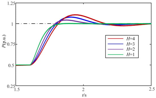
Figure 17.
Diagram of active power variation when D = 70 and H changes.
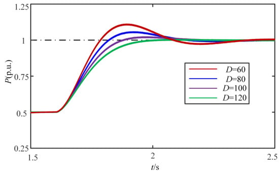
Figure 18.
Diagram of active power variation when H = 70 and D changes.
6. Conclusions
Aiming at the problems of bus voltage oscillation and current impact during the transition from off-grid to grid-connected, this paper proposes an active support pre-synchronization control strategy based on the third-order model of synchronous generators and carries out a small signal analysis on the active support control with secondary frequency modulation. Through simulation verification, the main conclusions are as follows:
- (1)
- An active support model with a frequency integral feedback link is established in off-grid mode, which effectively improves the frequency stability of local load in off-grid mode.
- (2)
- By reasonably setting and adjusting the values of H and D, the overshoot and dynamic response speed of active support control can be balanced, and the stability of the system can be improved.
- (3)
- A pre-synchronization control model based on the third-order model of active support is established. The voltage on both sides of the PCC is used to compensate for the frequency and voltage of the active frequency link and the excitation voltage link, respectively, and the fast and smooth grid-connected mode of the active support converter is realized.
Author Contributions
Conceptualization, C.L. and Y.Z.; methodology, L.Y.; software, J.M.; validation, Z.S. and Z.Y.; formal analysis, J.M.; investigation, Y.Y.; resources, Y.Z.; data curation, J.M.; writing—original draft preparation, Y.Z.; writing—review and editing, J.M. All authors have read and agreed to the published version of the manuscript.
Funding
This research was funded by State Grid Electric Power Co., Ltd., grant number 5100-202255370A-2-0-ZN.
Data Availability Statement
The original contributions presented in the study are included in the article, further inquiries can be directed to the corresponding author.
Conflicts of Interest
Authors Zhida Su and Zedong Yang were employed by the company China Electric Power Research Institute Co., Ltd. The authors declare that this study received funding from State Grid Electric Power Co., Ltd. The remaining authors declare that the research was conducted in the absence of any commercial or financial relationships that could be construed as a potential conflict of interest.
References
- Zhuo, Z.; Zhang, N.; Xie, X.; Kang, C. Key Technologies and Development Challenges of High Ratio Renewable Energy Power Systems. Autom. Electr. Power Syst. 2021, 45, 171–191. [Google Scholar]
- Huang, L.; Xin, H.; Huang, W.; Yang, H.; Wang, Z. Quantitative Analysis Method for Frequency Response Characteristics of Power Systems with Virtual Inertia. Autom. Electr. Power Syst. 2018, 42, 31–38. [Google Scholar]
- Cheng, C.; Yang, H.; Zeng, Z.; Tang, S.; Zhao, R. Adaptive control method for rotor inertia of virtual synchronous generator. Autom. Electr. Power Syst. 2015, 39, 82–89. [Google Scholar]
- Wang, B.; Yang, D.; Cai, G. Summary of research on inertia related issues in power systems under high proportion of new energy integration. Power Syst. Technol. 2020, 44, 2998–3007. [Google Scholar]
- Zhu, F.; Peng, Z.; Hu, W.; Wang, H.; Zhang, C.; Zhao, Z. An Improved VSG control strategy for Microgrid. In Proceedings of the 2021 IEEE International Conference on Electrical Engineering and Mechatronics Technology (ICEEMT), Qingdao, China, 2–4 July 2021; pp. 338–342. [Google Scholar]
- Wen, T.; Zhu, D.; Zou, X.; Jiang, B.; Kang, Y. Power Coupling Mechanism Analysis and Improved Decoupling Control for Virtual Synchronous Generator. IEEE Trans. Power Electron. 2021, 36, 3028–3041. [Google Scholar] [CrossRef]
- Liu, B.; Liu, Z.; Liu, J.; An, R.; Zheng, H.; Shi, Y. An Adaptive Virtual Impedance Control Scheme Based on Small-AC-Signal Injection for Unbalanced and Harmonic Power Sharing in Islanded Microgrids. IEEE Trans. Power Electron. 2019, 34, 12333–12355. [Google Scholar] [CrossRef]
- Qi, J.; Li, Y.; Tong, H.; Zhou, D.; Zhang, Y. A Power Second Order Decoupling Strategy for Pre synchronous VSG Based on Dynamic Virtual Current Feedforward. Power Syst. Technol. 2020, 44, 3556–3565. [Google Scholar]
- Zhou, P.; Zhang, X.; Di, Q.; Yue, J.; Xing, C. Pre-synchronization and grid-connected strategy of doubly fed wind turbines based on virtual synchronous machine control. Autom. Electr. Power Syst. 2020, 44, 71–78. [Google Scholar]
- Li, X.; Liu, G.; Yang, R.; Chen, G. Control Strategy and Seamless Switching Method for Virtual Synchronous Generators with Transient Damping Characteristics. Power Syst. Technol. 2018, 42, 2081–2088. [Google Scholar]
- Dong, D.; Wen, B.; Boroyevich, D.; Mattavelli, P. Analysis of phase-locked loop low-frequency stability in three-phase grid-connected power converters considering impedance interactions. IEEE Trans. Ind. Electron. 2014, 62, 310–321. [Google Scholar] [CrossRef]
- Atmaca, Ö.; Karabacak, M. Frequency, Phase, and Magnitude Difference Locked-Loop Based Linear Synchronization Scheme for Islanded Inverters and Microgrids. IEEE Access 2023, 11, 61748–61772. [Google Scholar] [CrossRef]
- Wang, X.; Wang, Y.; Liu, Y.; Liu, C.; Wang, S. Low voltage ride through control method for actively supported new energy units based on virtual reactance. Power Syst. Technol. 2022, 46, 4435–4444. [Google Scholar]
- Zhang, Q.; Peng, C.; Chen, Y.; Jin, G.; Luo, A. A control strategy for parallel operation of multi-inverters in microgrid. Proc. CSEE 2012, 32, 126–132+18. [Google Scholar]
- Liu, C.; Sun, T.; Cai, G.; Ge, W.; Ge, Y.; Yan, Y.; Liu, Y. Active Support Control and Primary Frequency Modulation Contribution Analysis of Battery Energy Storage Power Station Based on Synchronous Machine Third Order Model. Proc. CSEE 2020, 40, 4854–4866. [Google Scholar]
Disclaimer/Publisher’s Note: The statements, opinions and data contained in all publications are solely those of the individual author(s) and contributor(s) and not of MDPI and/or the editor(s). MDPI and/or the editor(s) disclaim responsibility for any injury to people or property resulting from any ideas, methods, instructions or products referred to in the content. |
© 2024 by the authors. Licensee MDPI, Basel, Switzerland. This article is an open access article distributed under the terms and conditions of the Creative Commons Attribution (CC BY) license (https://creativecommons.org/licenses/by/4.0/).