Article

ISOS-SAB DC/DC Converter for Large-Capacity Offshore Wind Turbine †

by
Xipeng Cai
1,2,
Yixin Liu
3,
Yihua Zhu
1,2,4,
Yanbing Zhou
5,
Chao Luo
1,2,4 and
Qihui Liu
5,*
1
State Key Laboratory of HVDC, Electric Power Research Institute, China Southern Power Grid, Guangzhou 510663, China
2
National Energy Power Grid Technology R & D Centre, Guangzhou 510663, China
3
Xiaolangdi Multipurpose Dam Project Management Center, Ministry of Water Resources, Zhengzhou 450003, China
4
Guangdong Provincial Key Laboratory of Intelligent Operation and Control for New Energy Power System, Guangzhou 510663, China
5
State Key Laboratory of Alternate Electrical Power System with Renewable Energy Sources, North China Electric Power University, Beijing 102206, China
*
Author to whom correspondence should be addressed.
This paper is an extended version of the paper: “An ISOS-SAB DC/DC Converter for Large Capacity Offshore Wind Turbine” presented to 2022 4th International Conference on Smart Power & Internet Energy Systems (SPIES), 2022, Beijing, China, December 2022, pp. 768–773, and published in IEEE Conference Proceedings.
Energies 2024, 17(20), 5071; https://doi.org/10.3390/en17205071
Submission received: 28 August 2024 / Revised: 1 October 2024 / Accepted: 9 October 2024 / Published: 12 October 2024
(This article belongs to the Section A3: Wind, Wave and Tidal Energy)

Abstract

:
This study offers a modular isolated grid-connected DC/DC medium-voltage DC aggregation converter to support offshore full DC wind farms’ need for lightweight and highly efficient power aggregation and transmission. The converter can simultaneously have a smaller transformer size and lower switching frequency during operation through the dual-voltage stabilization three-loop control strategy and phase-shift modulation strategy, which greatly reduces the space occupied by the converter and lowers the switching loss, Additionally, the use of a two-level structure at a lower switching frequency has lower loss, which effectively reduces the cost of the power device compared with the commonly used three-level converter. The input series output series connection between the converter sub-modules effectively lowers the voltage stress on each power switching device and facilitates expansion into a multi-module structure, expanding its application in high-voltage and large-capacity environments. This study analyzes the two working modes of the DC/DC converter and its control approach, in addition to providing a detailed introduction to the application scenarios of this converter. Ultimately, the efficacy and practicability of the suggested topology and control scheme are confirmed by simulations and experiments.

1. Introduction

With the development and utilization of renewable energy, wind energy has shown great potential, particularly for offshore wind farms. Currently, AC wind farms are mature. However, with the increasing capacity of offshore wind farms and the increasing distance from the shore, the wind power integration scheme of wind farms has tended to gradually change to DC collection and transmission. As offshore wind capacities and distances from the shore increase, DC wind farms offer advantages over their AC counterparts. They eliminate bulky AC transformers, reduce reactive power loss, and cut costs for offshore converter stations. The two-stage boost structure proves more practical and energy-efficient than centralized DC boosts, providing a viable solution for the evolving needs of offshore wind farms [1,2,3,4].
Despite the diminishing weight and volume of wind turbines, their capacities are on the rise. Presently, global wind turbine rated power exceeds 10 MW, with 20 MW turbines in the design and construction stages [5]. Wind power converters are pivotal in wind power generation systems, making large-capacity high-voltage power electronic converters indispensable for offshore wind power systems.
The key component of a DC wind farm with a two-stage boost structure is the medium voltage DC/DC converter. This needs to meet the requirements of high capacity and high voltage gain in the 10 MW class [6]. The literature [7,8] suggests the use of various thyristor resonant converters to increase the voltage by controlling the instant of thyristor conduction to increase the voltage gain, as well as a compact design that is suitable for offshore wind farms. Bidirectional resonant converters also play an important role in fault isolation [9]. However, such converters require multiple high-voltage AC capacitors and switching devices, which are very challenging to install in the narrow chassis of a wind turbine. The literature [10,11] also describes a resonant switched-capacitor DC-DC converter, which is able to easily achieve large voltage gains and soft switching. Nevertheless, its complex structure limits its practical application. The literature [12] presents a transformerless adjustable gain non-isolated DC-DC boost converter with a multi-port flexible power supply, reduced switching voltage stress, and reasonably good range efficiency. All the above-mentioned converters are non-isolated and impose stringent requirements on the insulation, safety, and reliability of the wind turbine.
The isolation converters that have relatively low requirements for the above-mentioned performances usually include a phase-shifted full bridge, single active bridge (SAB), dual active bridge (DAB), and series resonant converters [13,14,15]. DAB-type converters are mature and widely used, with low voltage and current stress on the switching devices, therefore they are suitable for applications with high output voltages and currents. However, for the whole offshore wind energy system, the DC converter is only required to realize unidirectional energy transfer [16,17], which is more economical and cost-effective than the DC converter being used for bidirectional energy transfer. This is due to the fact that the direction of energy transfer in offshore wind energy systems is fixed, i.e., from offshore to onshore. Although, a single SAB converter is not suitable for high-voltage, high-capacity applications due to the limitations of switching device ratings. However, a modular structure can be used for capacity expansion and to increase the voltage carrying capacity, and the modular converter topology can meet the voltage and capacity requirements of offshore DC wind farms [18]. The modular converter topology is easy to expand, facilitates redundant control, and provides greater flexibility in selecting sub-module topologies and control modes. A novel modular multilevel converter (MMC) configuration is introduced in the literature [19]. It relies on the parallel connection of three-level active neutral clamp (3 L-ANPC) cells to achieve modularity and significantly improve efficiency and power density, while drastically reducing the passive component values and overall switching losses. However, the control strategy is intricate and requires the use of additional switching devices. The literature [20] describes a control system for a two-stage boost DC/DC converter based on an inner loop with a sliding mode controller and an outer loop with an integral type controller to ensure its robustness to load and input voltage variations as well as converter parameter uncertainties.
For the combination of modular converters, the selection of sub-modules and the combination method are crucial. There are usually four combination methods: input in series output in series (ISOS), inputs in parallel and outputs in series (IPOS), inputs in series and outputs in parallel (ISOP), and inputs in parallel and outputs in parallel (IPOP). In the application scenario of full DC large-capacity offshore wind farms, the ISOS and IPOS methods are able to withstand higher voltage levels and transmit more power. However, IPOS also has limitations in that it requires a higher voltage withstand for the power devices on the input side of the DC/DC converter. In the selection of sub-modules, the more mature topologies are the three-level clamp structure and the two-level structure. The power switching device voltage requirements are lower for the three-level compared to the two-level. In the high-frequency operating environment, the loss is lower, but in the lower-frequency operating environment, the three-level structure will lose the advantage [21] and the number of power switching devices used is greater than in the two-level structure, which will increase the construction cost. The two-level structure can effectively reduce the voltage withstand requirement of individual power devices in ISOS mode.
This paper introduces the design of a modular boost DC/DC converter based on a two-level single active bridge, combining multiple modules with input in series and output in series (ISOS) to fulfill the grid connection requirements of DC wind turbines. This approach not only reduces the required input and output voltage levels of a single sub-module, but also decreases the need for the device to withstand the voltage and facilitates the expansion into multi-module converters. This combination resolves the issues arising from the voltage and power transmission limitations of a single DC/DC converter. Furthermore, the output voltage is effectively enhanced by connecting the outputs in a series. The dual-voltage stabilized three-loop control strategy and phase-shift modulation strategy was proposed, aligning with the characteristics of the ISOS topology. Finally, MATLAB(23.2.0.2599560(R2023b))/Simulink simulations and semi-physical experiments were conducted to validate the accuracy and dependability of the converter topology and the corresponding control strategy.

2. Grid-Connected DC/DC Converter Based on Phase-Shifting Full Bridge for Wind Turbine

Compared to doubly fed turbines, direct-driven wind turbines prove more suitable for deep-sea DC wind farms [16]. Figure 1 illustrates an all-DC parallel two-stage boosted offshore wind farm with an offshore boosting platform and direct-driven wind turbines. Power is transmitted to the coast through a high-voltage direct current (HVDC) line, connected to the grid via an onshore converter.
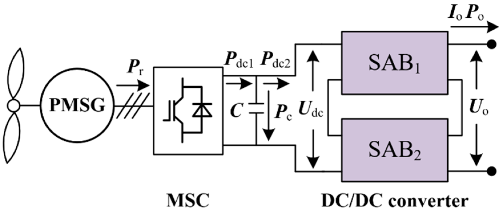
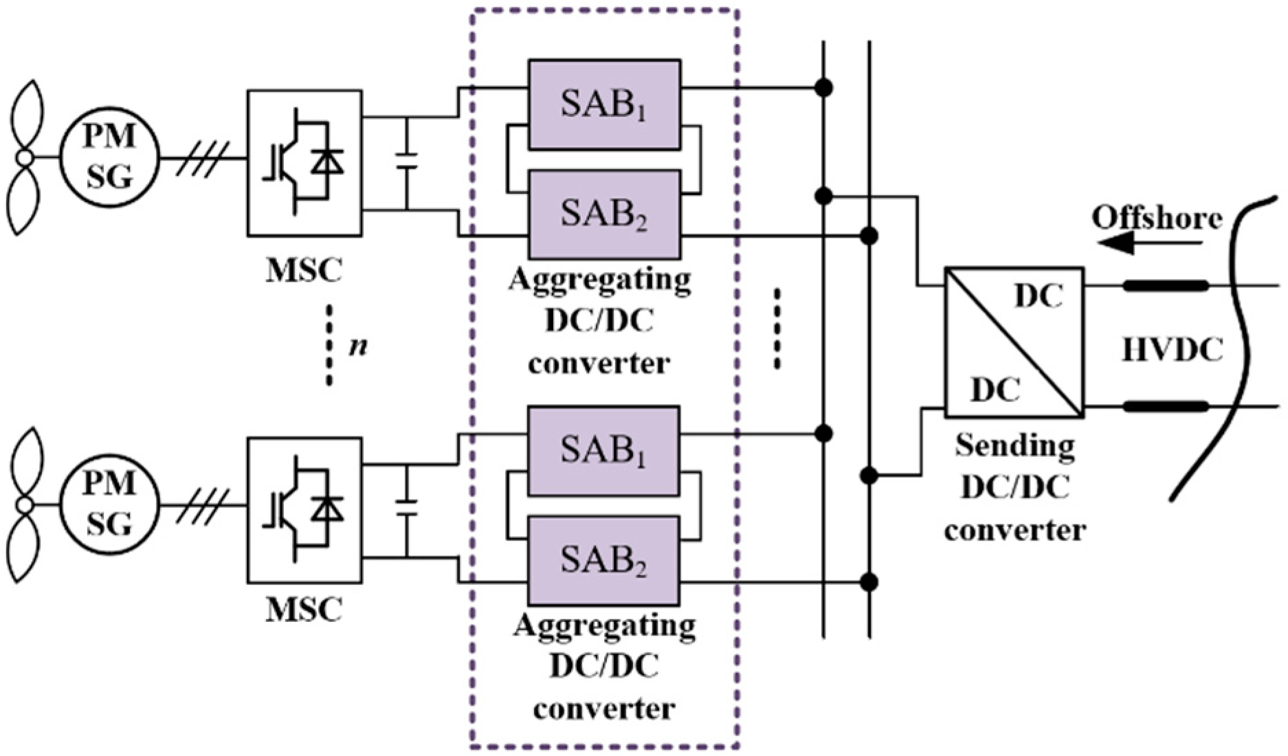
The direct-driven DC output-type wind turbine in Figure 2 comprises an ISOS modular combination DC/DC boost converter, a machine-side converter (MSC), and a permanent magnet synchronous generator (PMSG). The PMSG generates medium-voltage DC power through MSC rectification and the ISOS-SAB converter’s boosting link.
Given the full bridge diodes on the rectifier side of the DC/DC converter, power flows in one direction. In Figure 2, Pr is the generator’s active power output, Pdc1 is the MSC’s active power output, Pc is the absorbed active power of the MSC’s output capacitor, C is the value of the MSC output side capacitance, Udc is the capacitor voltage, Pdc2 is the input power of the DC/DC boost converter, Po is the output power of the DC wind power generation system, Uo is the output voltage, and Io is the output current.
Ignoring the active power loss of the system, based on the power balance relation of the DC/DC converter, Po, Pdc2, Pr, and Pdc1 have the following relationships:
P o = P dc 2
P r = P dc 1
The energy W stored by the output capacitor of the PWM rectifier is
W = 1 2 C U dc 2
The absorbed active power of output capacitor can be expressed by
P c = d W d t = 1 2 C d U dc 2 d t
Pdc1, Pdc2, and Pc satisfy the following relation:
P dc 2 = P dc 1 + P c
Combined with (1)–(5), it can be obtained from
P o = P r + 1 2 C d U dc 2 d t = U o I o

3. Working Mode Analysis of SAB Converter

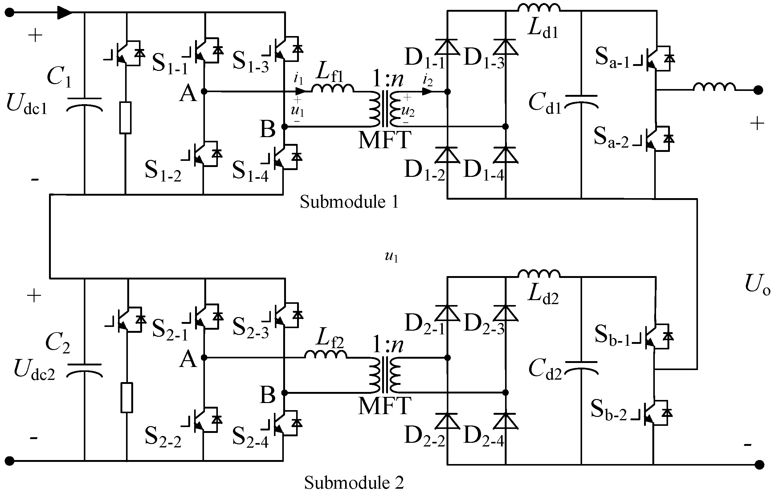
A single SAB converter exhibits limitations on power and voltage. In the context of a permanent magnet direct-drive DC wind power system, the modules need to be arranged in a series and in parallel to meet the medium voltage and high power requirements. This study utilized an SAB converter as the fundamental module, connecting two such modules in series at the input and output terminals to create an ISOS-SAB isolated DC/DC converter. The circuit topology is depicted in Figure 3.
The traditional single active bridge converter has power and voltage limitations, and the modules need to be connected in parallel in a series to meet the technical requirements of medium voltage and high power in the application scenario of permanent magnet direct-drive DC wind power systems. The two-level single active bridge converter was chosen as the DC/DC converter sub-module in this paper because, while the harmonic loss of the currently widely used three-level structure is smaller, it still has a significant advantage over the loss in the inverter section of the two-level and three-level structures at lower switching frequencies [21]. The two sub-modules with inputs connected in series and outputs connected in series are used to form the SAB-based ISOS-SAB isolated DC/DC converter topology to reduce the loss, while lowering the cost and meeting the lightweight requirements.
Symbols:
-
Udc1 and Udc2: input voltages of the two basic modules;
-
Uo1 and Uo2: output terminal voltages of the two basic modules;
-
C1 and C2: input capacitance of the two basic modules;
-
Cd1 and Cd2: output capacitance of the two basic modules;
-
k: voltage change ratio of the intermediate-frequency isolation transformer;
-
n: transformer turns ratio;
-
Lf1 and Lf2: leakage inductances of the transformer;
-
Ld1 and Ld2: filter inductances of the transformer;
-
u1 and u2: primary and secondary voltages of the transformer;
-
i1 and i2: primary and secondary currents of the transformer.
The voltage and current relationship across the intermediate-frequency transformer sides is expressed in Equations (7) and (8).
k = u 2 n u 1
k = i 1 n i 2
In the design of the converter modulation strategy, because of the converter’s application scenario for full DC offshore wind farms and the working environment of the wind turbine generator’s narrow chassis, the converter’s volume is highly required in the design of the modulation strategy. Generally speaking, the greater the operating frequency of the medium voltage transformer in the converter, the smaller the transformer volume, so the converter’s operating frequency should not be too low in order to minimize the converter’s volume. The switching loss increases significantly when the usual SPWM modulation is utilized since the converter’s switching frequency is significantly higher than its operating frequency. By using the phase-shift modulation technique, the demand between the converter volume and the switching frequency can be balanced by making the switching frequency equal to the MV transformer’s working frequency.
Therefore, a single active bridge employs a phase-shift modulation strategy to control DC/DC output power through phase-shift angles on the DC/DC inverter side. The phase-shift ratio is defined as the proportion of the phase-shift angle in the half-switching cycle. Where d represents the phase-shift ratio, T is the switching period, and the phase-shift angle is dT/2. Switch devices (IGBT) are modulated by a PWM wave with a 50% duty cycle, with complementary conduction between the upper and lower switch devices of the same bridge arm. SAB converters operate in discontinuous current mode (DCM) and continuous current mode (CCM), influenced by the phase-shift ratio d [22]. By controlling the transmission power, the shift ratio can be adjusted, enabling the SAB converter to operate in different modes. Each bridge arm’s top and bottom two IGBT signals are designated by the letters S1, S2, and S3, S4.

3.1. CCM Mode

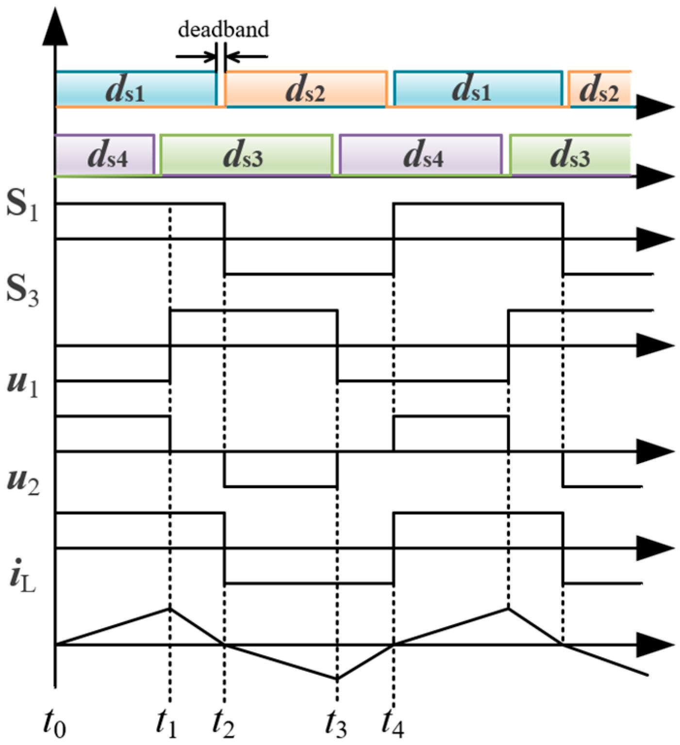
When the DC/DC converter works in CCM mode, the change process of the inductance current can be divided into four stages in a complete switch cycle. Assuming that the flow direction from left to right is positive, the inductance current can be expressed by the following formula.
d i d t = u 1 u 2 L s
A waveform diagram of a DC/DC converter working in CCM mode can be drawn as in Figure 4.
In Stage 1, t ∈ (to, t1), the switching devices S1 and S4 are turned on, S2 and S3 are turned off, the flow direction of iL is from left to right, the current value increases gradually, and the voltage at both ends of inductor Ls also increases gradually, u1 = U1, u2 = U2.
d i L d t = U 1 U 2 / n L s
In Stage 2, t ∈ (t1, t2), the switching devices S1 and S3 are turned on, S2 and S4 are turned off, the flow direction of iL is from left to right, the current value decreases gradually, and the voltage at both ends of inductor Ls also decreases gradually, u1 = 0, u2 = U2.
d i L d t = U 2 / n L s
In Stage 3, t ∈ (t2, t3), the switching devices S2 and S3 are turned on, S1 and S4 are off, the flow direction of iL is from right to left, the current value increases gradually, and the voltage at both ends of inductor Ls also increases gradually, u1 = −U1, u2 = −U2.
d i L d t = U 1 + U 2 / n L s
In Stage 4, t ∈ (t3, t4), the switching devices S2 and S4 are turned on, S1 and S3 are turned off, the flow direction of iL is from right to left, the current value decreases gradually, and the voltage at both ends of inductor Ls also decreases gradually, u1 = 0, u2 = −U2.
d i L d t = U 2 / n L s
The average power of an SAB converter in one cycle can be obtained from
P CCM = 1 T t 0 t 4 i 1 u 1 d t = d k U 1 2 T L s

3.2. DCM Mode

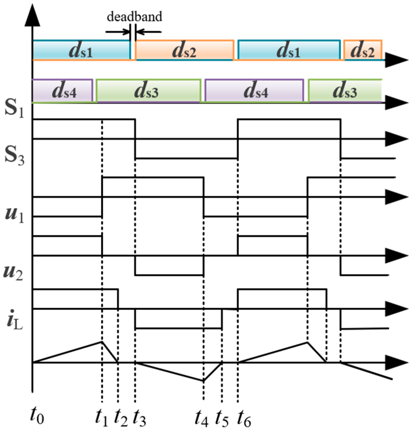
The DCM principle of operation waveform is shown in Figure 5.
In Stage 1, t ∈ (to, t1), the switching devices S1 and S4 are turned on, S2 and S3 are turned off, the flow direction of iL is from left to right, the current value increases gradually, and the voltage at both ends of inductor Ls also increases gradually, u1 = U1, u2 = U2. The expression is shown in Equation (10).
In Stage 2, t ∈ (t1, t2), the switching devices S1 and S3 are turned on, S2 and S4 are turned off, the flow direction of iL is from left to right, the current value decreases gradually, and the voltage at both ends of inductor Ls also decreases gradually, u1 = 0, u2 = U2. The expression is shown in Equation (11).
In Stage 3, t ∈ (t2, t3), the switching devices S1 and S3 are turned on, and S2 and S4 are turned off, iL = 0, u1 = 0, u2 = 0.
In Stage 4, t ∈ (t3, t4), the switching devices S2 and S3 are turned on, S1 and S4 are turned off, the flow direction of iL is from right to left, the current value increases gradually, and the voltage at both ends of inductor Ls also increases gradually, u1 = −U1, u2 = −U2. The expression is shown in Equation (12).
In Stage 5, t ∈ (t4, t5), the switching devices S2 and S4 are turned on, S1 and S3 are turned off, the flow direction of iL is from right to left, the current value decreases gradually, and the voltage at both ends of inductor Ls also decreases gradually, u1 = 0, u2 = −U2. The expression is shown in Equation (13).
The average power of an SAB converter in one cycle can be obtained from
P DCM = 1 T t 0 t 6 i 1 u 1 d t = 1 d 2 ( 1 k ) U 1 2 T 4 L s
The CCM working mode analyzed in this paper is a critical condition. On this basis, when the leakage inductance current change rate increases, the leakage inductance current will flow back to the capacitor branch at the input end to charge the capacitor. At this time, the phase-shift angle of the switching device of the DC/DC converter will become zero, so the power of the converter cannot be well controlled. Therefore, the DC/DC converter designed in this paper works in DCM mode.

4. The Control Strategy of DC/DC Converter

The average power transfer formula for the DC/DC converter underscores the necessity of the MSC achieving direct torque control of the PMSG. Simultaneously, the DC/DC converter must regulate the DC voltage at the MSC’s output. Consequently, the back-end medium-voltage DC/DC converter plays a vital role in stabilizing the front-end MSC’s output voltage. The primary control goal of the DC/DC converter is to maintain a consistent voltage on the input side, aligning with the operational requirements of offshore DC wind farms, despite deviating from the conventional output voltage in comparison with the reference value.
Given the connection between the two modules, the input and output are in series, so voltage balance becomes imperative. The literature [22] highlights that for any ISOS-type converter, the control system governing equalized voltage or current output is inherently unstable. With the inputs connected in series, the current on the input side of the two sub-modules is naturally equal, which ensures that the sub-module output powers are equalized by controlling the input equalized voltage [23].

4.1. Steady-State Period Control Strategy

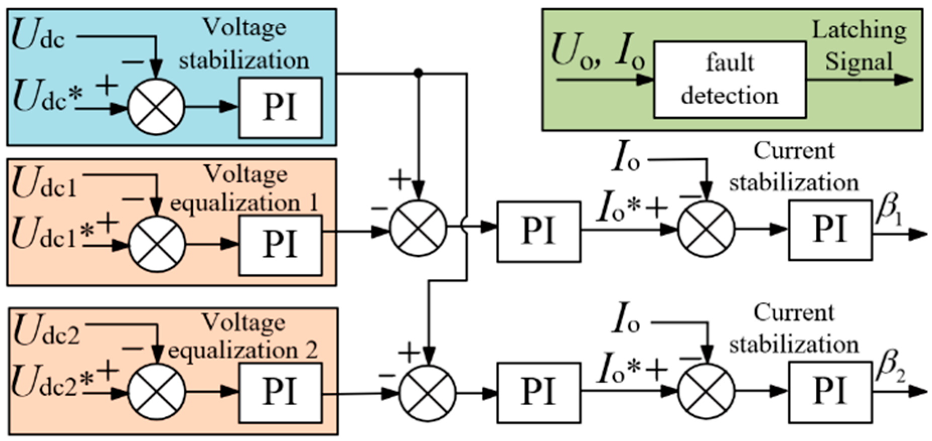
Ensuring the stability of the absorbed power in the DC/DC converter is essential for voltage stabilization. For a single sub-module, the transmission power of that module dictates the voltage stabilization, with this transmission power being directly influenced by the shift ratio β. Consequently, a three-loop control strategy, centered on dual-voltage stabilization, was implemented, considering the phase-shift angle as the control parameter. The regulator loop manages the stabilization of the MSC’s output capacitor voltage, the equalizer loop is responsible for stabilizing each sub-module’s input capacitor voltage, and the current inner loop is ultimately employed to determine the phase-shift ratio β, as illustrated in Figure 6.
In Figure 6, Udc* represents the specified reference value for the converter front-stage MSC output capacitor voltage, equivalent to the designated reference value for the converter input voltage. Udc denotes the measured value of the aggregated converter input voltage. Udc1* and Udc2* are the specified values for the input voltages of each sub-module, while Udc1 and Udc2 represent the measured values of the input voltages for each sub-module. β1 and β2 denote the phase-shift angles of the two sub-modules, respectively. Io* corresponds to the reference value of the converter output current, and Io represents the measured value of the converter output current.
The converter control strategy is divided into two loops: one dedicated to voltage control and the other to current control. The voltage control loop encompasses sub-module input voltage equalization and input voltage stabilization controls. The current control aspect is derived within the voltage control loop by comparing the disparity between the actual input voltage Udc of the converter and the provided reference value Udc* with the reference value of each sub-module through the PI regulator. Simultaneously, the reference values Udc1* and Udc2* of the sub-module converter are contrasted with the actual input voltages Udc1 and Udc2, respectively, in the voltage equalization control link. The resultant difference values are subsequently juxtaposed with the current control component of the converter, acquired via the PI regulator in the preceding section.
This process also yields the reference values for the converter’s output currents, which are then compared with the converter’s output current from the voltage control loop and matched with the converter’s measured output current in the current control loop. The PI regulator is then employed to determine the shift ratios, β1 and β2, for the sub-module, and the trigger control signal of the sub-converter is obtained through phase-shift modulation.

4.2. Failure Period Control Strategy

A short circuit fault occurring in a wind farm pooling line leads to a drop in voltage at the grid connection point. Despite this, the turbines continue operating at maximum wind tracking. This scenario implies that the generated power cannot be promptly dispatched, potentially causing power redundancy and a sharp increase in the DC bus voltage. Therefore, to navigate the fault period and restore regular wind farm operations after fault resolution, an efficient mechanism (depicted in Figure 7) must be employed.
To mitigate a substantial decrease in output, the DC/DC converter must promptly detect a short circuit fault at the DC pooling bus through the output voltage and current and then block it. At this juncture, the half-bridge blocking unit on the converter’s output side is activated, disconnecting switching tubes Sa-1 and Sb-1 (which are open during steady state operation) and turning off switching tubes Sa-2 and Sb-2 (which are disconnected during steady state operation). Consequently, the output side capacitor voltage experiences a significant drop. To dissipate the excess power and prevent a sudden rise in the converter’s input voltage during wind turbine power redundancy conditions, the Chopper dissipation circuit comes into play.
After the fault is rectified, the converter is unblocked, Sa-1 and Sb-1 are turned on, Sa-2 and Sb-2 are turned off, the energy dissipation circuit is closed, and stable operation is restored.

5. Simulation and Experimental Verification

5.1. Simulation Verification

The ISOS-SAB medium-voltage converging converter for offshore wind farms, as shown in Figure 8, is modelled in the MATLAB/Simulink platform with the input voltage set to 6 kV, the output voltage set to 60 kV, and the rated capacity set to 10 MW in order to confirm the viability of the designed ISOS-SAB converter topology. Investigations were conducted into the system’s operating characteristics under various operating situations, and Table 1 displays the pertinent simulation parameters.
The permanent magnet wind turbine operates at full power turntable when the wind speed stabilizes at 10 m/s. At this point, the generator output power is 10 MW and it is in a stable operating condition. Rather than using the permanent magnetism direct-drive wind turbine model, the input side of the ISOS-SAB converter model was employed in this research to replicate circumstances where the input voltage is under control, while also sending out electricity with a regulated current source. The DC/DC converter’s total input voltage is Udc. The two sub-modules’ input voltages are Udc1 and Udc2, and their output voltages are Uo1 and Uo2. The two sub-modules’ output voltages are denoted by Uo1 and Uo2.
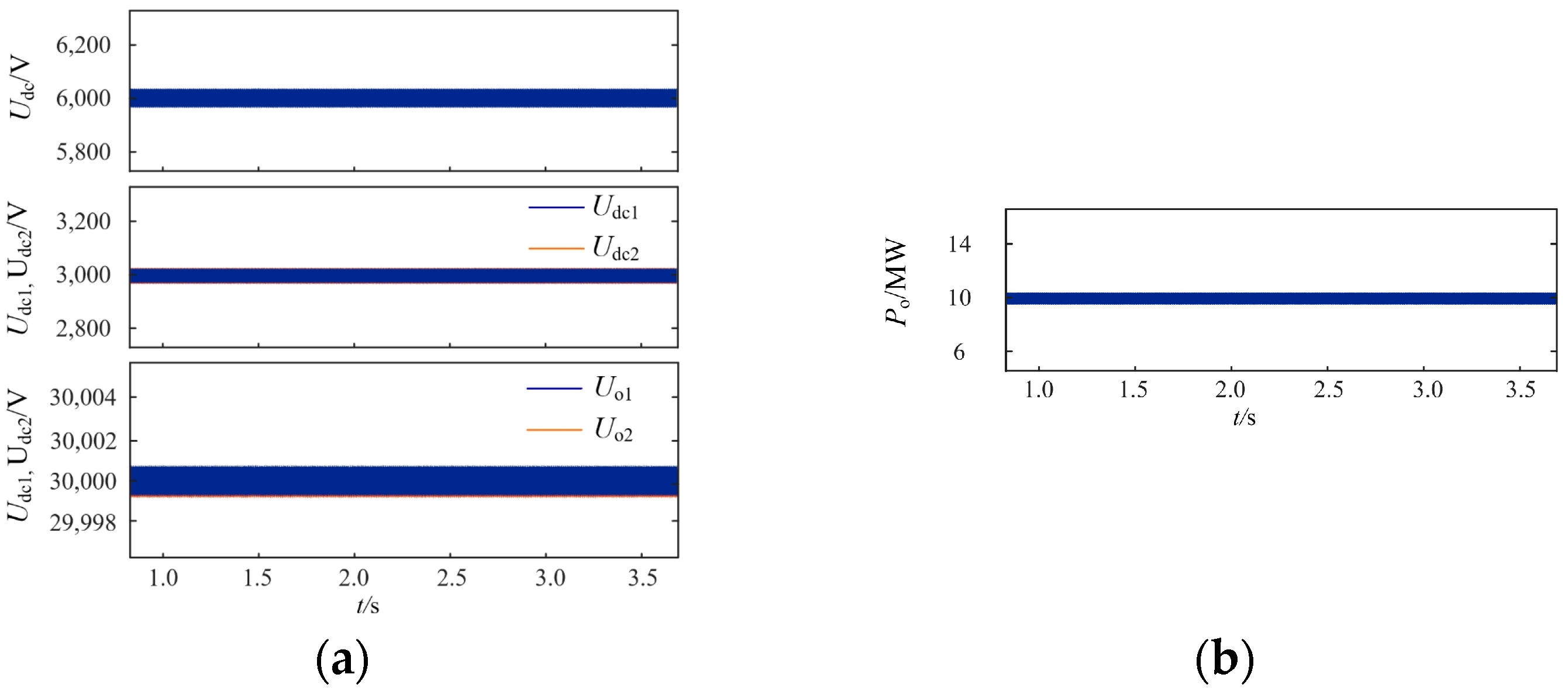
As illustrated in Figure 9a, when the turbine produces its rated power, the DC/DC converter’s voltage can be well stabilized and controlled, resulting in a total input voltage of 6 kV. The sub-modules can also achieve good voltage equalization, with the input voltage of each module being stabilized at 3 kV. The output voltages of the two sub-modules can also be stabilized at 30 kV. Figure 9b shows that the converter transmission capacity is also stabilized at 10 MW, confirming the accuracy of the control strategy.
The voltage and current across the medium frequency transformer of the DC/DC converter is shown in Figure 10.
As demonstrated in Figure 10, the medium-frequency transformer is capable of effectively fulfilling its job of lifting voltage and transferring power, and the converter can operate steadily in DCM mode.
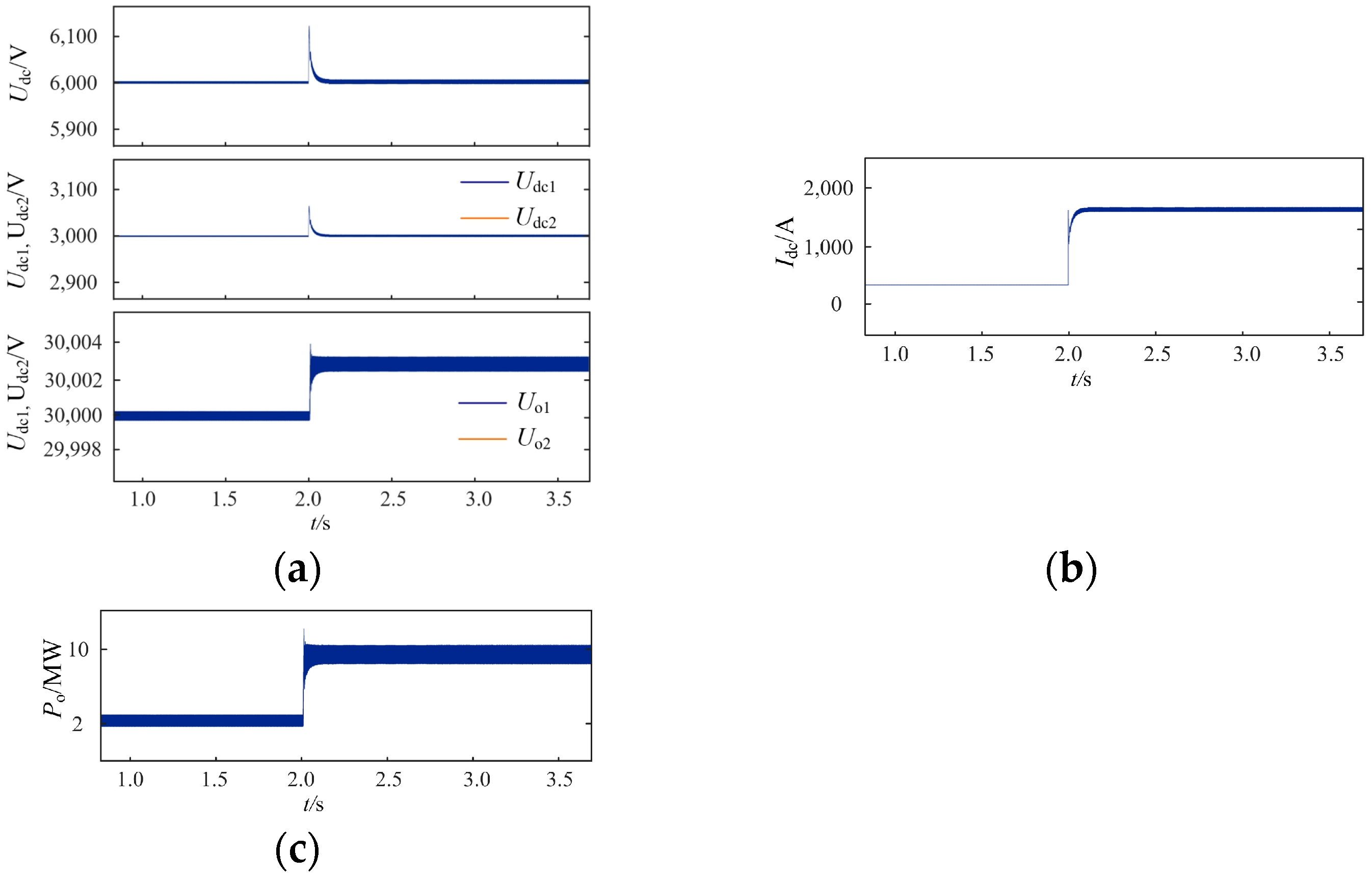
Furthermore, a simulation with varied operating conditions was carried out, in which an abrupt variation in wind speed would cause an abrupt variation in power. As a result, the simulation mimics the abrupt change in wind speed by using the abrupt change in power. The simulation is run for two seconds, during which the converter’s input power is adjusted from 2 MW to 10 MW. The converter’s input and output voltage waveforms, as well as the waveforms of the sub-modules’ input and output voltage and transmission capacity under the aforementioned variable case working conditions, are depicted in the accompanying figure.
The overall input voltage of the converter experiences a brief jump at 2 s in the variable case simulation waveforms, as seen in Figure 11a, but it subsequently stabilizes swiftly at the intended value of 60 kV. The sub-module input voltage continues to surge in the same manner as the total input voltage, until quickly stabilizing at 30 kV once more. The reliability of the topology design and control strategy under variable operating conditions was demonstrated by the sub-module’s output voltage appearing in a new steady state shortly after the power mutation occured. The input current also spikes at 2 s and, as predicted, stabilizes at 1666 A, as seen in Figure 11b. The transmission capacity in Figure 11c stabilizes at 2 MW prior to the mutation and increases to 10 MW shortly after the input power mutation.
In order to verify the effectiveness of the converter fault ride-through strategy, a bipolar short circuit fault occurs at the converter convergence bus for a duration of 200 milliseconds when the simulation is running normally for 1 s. Figure 12 shows the waveform of the converter input voltage Udc and phase shift α (α = −360 (β ± x), x = 0, 1, 2…) before and after the short circuit fault occurs. Among them, the phase shift and the phase-shift ratio can be converted, while the phase shift is periodic.
The converter goes through three stages before and after the short circuit fault, as shown in the Figure 12a. The steady state operating stage occurs before 1 s, the fault occurrence stage lasts from 1 s to 1.2 s, and the stage after the fault is removed after 1.2 s. The input voltage is stabilized at 6 kV during steady state operation; at 1 s, a short circuit fault occurs, causing the grid point voltage to drop significantly and activating the half-bridge blocking unit. At this point, the wind turbine generators are still in the wind maximum tracking mode, causing the input voltage to rise and activating the energy dissipation circuit. The fault is cleared at 1.2 s, at which point the energy-consuming circuit and the half-bridge blocking circuit are removed sequentially. As Figure 12 illustrates, even though there is a brief increase in voltage following the fault, the input voltage will not always be out of control. In fact, it can swiftly return to its initial stable state once the fault is fixed, demonstrating the viability of the fault processing mechanism in the control strategy. From Figure 12b, it can be seen that the numerical value of the phase-shift quantity changes before and after the fault occurs, but the phase-shift effect remains unchanged due to its periodicity, whereby the difference between the values before and after the fault is an integer multiple of the period.

5.2. Experimenal Verification

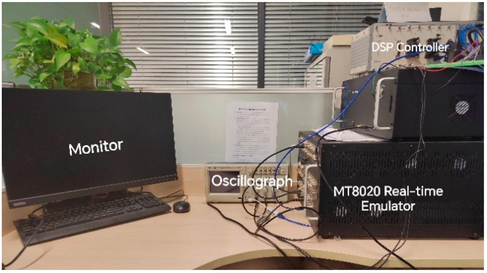
As illustrated in Figure 13, semi-physical experiments were conducted on the experimental platform (hardware-in-the-loop platform) comprising a Modeling-Tech real-time simulator and DSP controller in order to further confirm the efficacy and reliability of the designed converter topology and the corresponding control strategy. The relevant circuit parameters were consistent with those of the previously mentioned MATLAB/Simulink simulation model. The main circuit of the converter was imported using LC modeling into Modeling-Tech’s MT8020 real-time simulator (Shanghai, China), while the control part was burned by the DSP controller, and the two were connected to the corresponding IO signals through external wires.
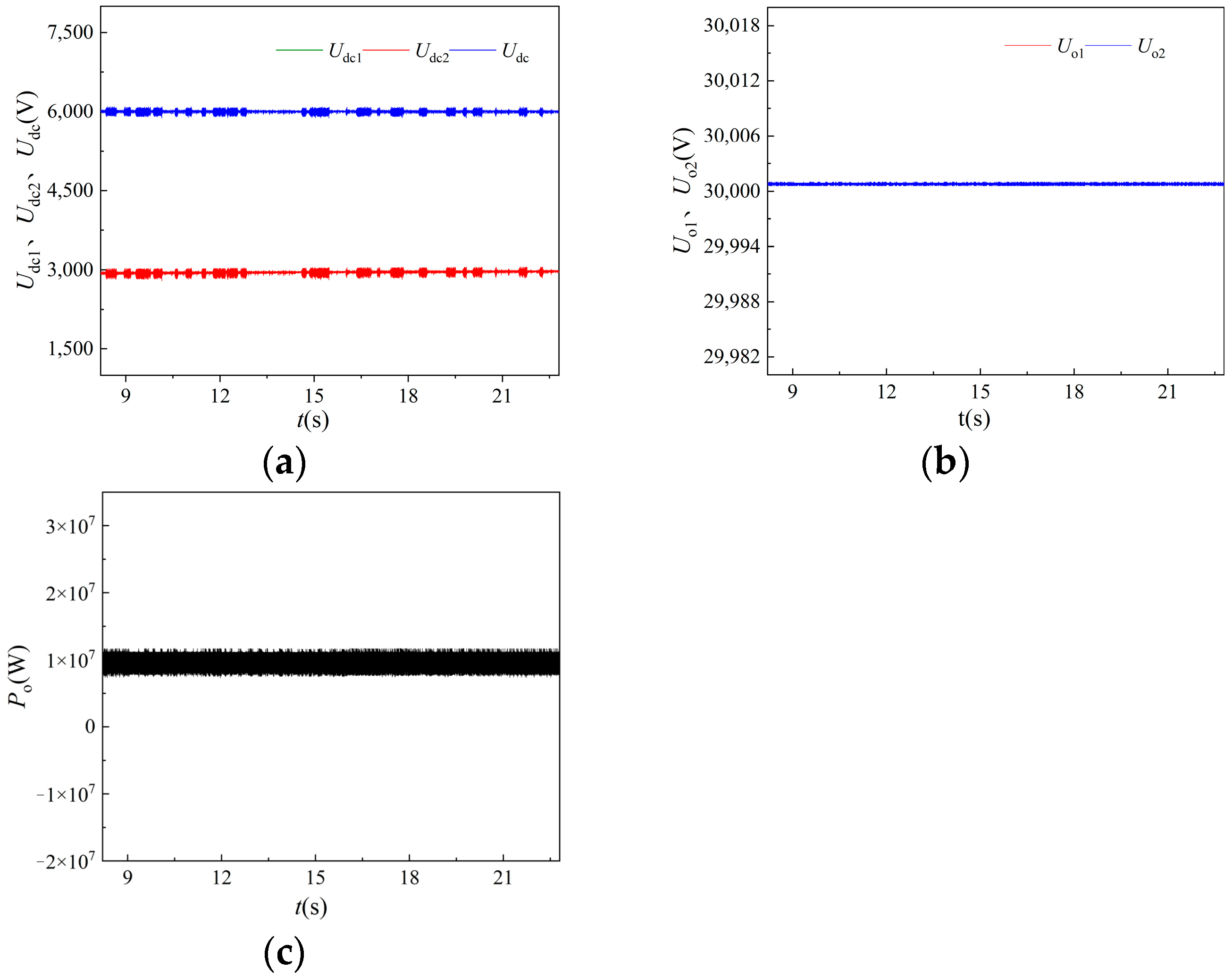
The input voltage waveform of the ISOS-SAB converter in the semi-physical experiments can also be maintained at 6 kV under stable working conditions when the turbine-side outputs rated power, as shown in Figure 14. The input-side voltage of the sub-module is also stabilized at the desired value of 3 kV, and the equalization effect is good. The output voltage is maintained at 30 kV, and the transmission capacity is stabilized at 10 MW. The overall impact is in good accord with the Simulink offline simulation, despite the waveforms appearing slightly burry. This further validates the viability of the control approach and topology design under the stable working state.
In the semi-physical experiment, the converter’s input power is programmed to abruptly change from 2 MW to 10 MW for 15 s. The following figures display the experimental waveforms of the sub-module input and output voltages, the transmission capacity, and the converter’s input voltage and current.
The total input voltage of the converter, the input voltage of the sub-module, and the output voltage of the sub-module all have experimental waveforms. As Figure 15 illustrates, these waveforms are similar to the simulation waveforms and have small errors between them, further demonstrating the dependability of the topology design and the control strategy under variable operating conditions.
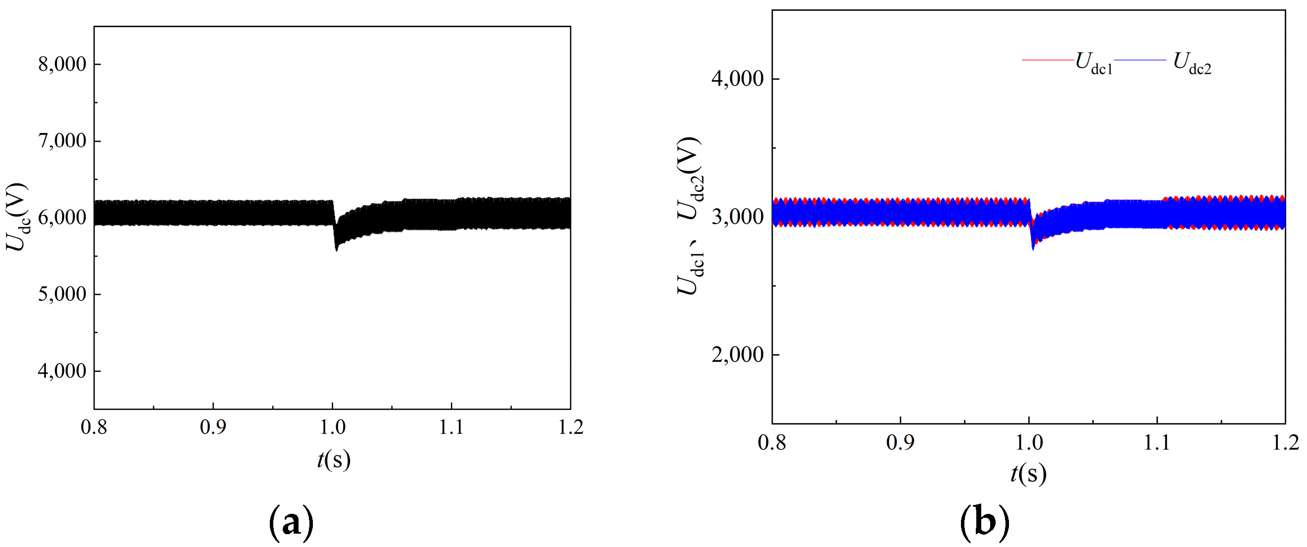
The semi-physical experiment additionally sets up the DC converging network fluctuation condition on the converter’s output side. After one second of operation, the experiment’s DC converging network voltage drops from 60 kV to 57 kV. As shown in Figure 16, when the converging network voltage drops in the event of this situation, the input voltages of the converter Udc, and the sub-modules, Udc1 and Udc2, experience a slight decrease in input voltage, but can rapidly return to the preset value. Similarly to this, when the total network voltage drops, the input currents somewhat increase but can rapidly return to their initial values.
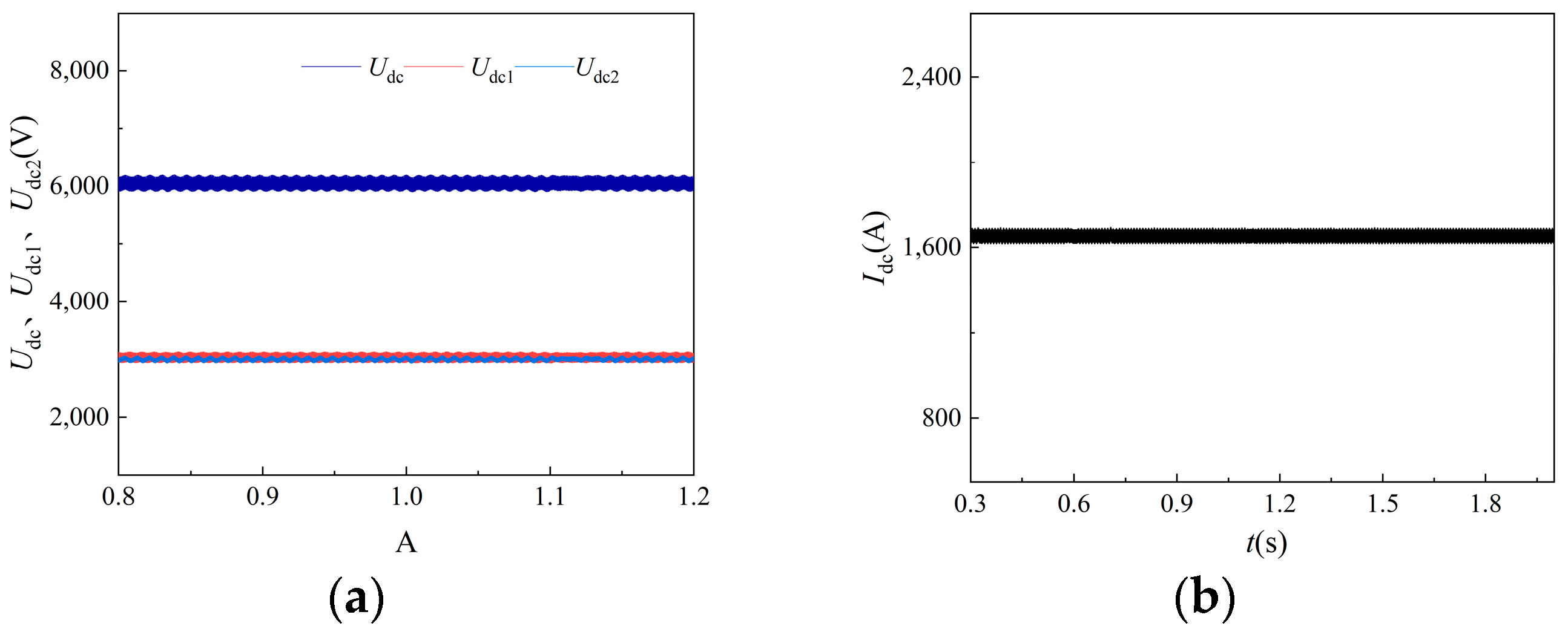
In the converter with modular characteristics, the input capacitor voltage imbalance is a more common problem, so in order to further verify the reliability of the converter’s control strategy under the above environment, the input capacitance of the two sub-modules is set to be inconsistent at the time of the experiment, and the results of the experiment are shown in Figure 17, in which the input voltage of the converter, the input voltage of the sub-modules and input current are all not significantly affected.

6. Conclusions

This study presents the design of a step-up grid-connected DC/DC converter based on the ISOS-SAB structure. The converter is applied to a permanent magnet direct-drive DC wind turbine and is used in the context of a full DC offshore wind farm. The findings of this study are as follows.
(1)
The sub-module topology uses a two-level single active bridge structure, which has a lower switching loss than a three-level structure at a switching frequency of 1 kHz. The DC/DC converter adopts an ISOS modular structure that can effectively reduce the voltage level of the switching devices, making it possible to use low-withstanding voltage switching devices, reduce the medium frequency transformer and sub-module series double boosting, and lower the requirements for transformer insulation. Compared with the three-level structure, there is a low switching loss at a switching frequency of 1 kHz. Additionally, fewer switching devices are used, saving money on device costs;
(2)
This study is valuable for optimizing converter performance by analyzing the potential of converter sub-modules in different operating states. It introduces a dual-regulator three-loop control strategy designed to minimize the switching frequency of power-switching devices. This strategy aims to strike a balance between efficient control and rapid response, indicating a potential improvement in the overall converter efficiency and stability;
(3)
Finally, a pertinent model with an input voltage, output voltage, and transmission capacity of 6 kV and 60 kV, 10 MW, respectively, was established. A semi-physical experiment on a real-time simulation platform and a simulation on the MATLAB/Simulink platform verified the reliability of the designed ISOS-SAB-type DC/DC converter and its control strategy.

Author Contributions

Conceptualization, X.C. and Y.L.; methodology, X.C.; software, Y.L. and Y.Z. (Yihua Zhu); validation, Y.Z. (Yihua Zhu); formal analysis, Y.L. and Y.Z. (Yihua Zhu); investigation, X.C. and Y.L.; resources, X.C.; data curation, Y.Z. (Yanbing Zhou); writing—original draft preparation, X.C. and Y.L.; writing—review and editing, Y.Z. (Yihua Zhu) and Y.Z. (Yanbing Zhou); visualization, C.L. and Y.Z. (Yanbing Zhou); supervision, C.L.; project administration, Q.L.; funding acquisition, X.C. All authors have read and agreed to the published version of the manuscript.

Funding

This work was supported by National Key Research and Development Program of China (2023YFB4203200, 2023YFB4203204).

Data Availability Statement

Data are contained within the article.

Conflicts of Interest

The authors declare no conflicts of interest.

References

  1. Cai, X.; Shi, G.; Chi, Y.-N. Research status and future development of offshore full DC type wind farms. Chin. J. Electr. Eng. 2016, 36, 2036–2048. [Google Scholar]
  2. Jiang, D.-Z.; Gu, H.-J.; Yi, R. Research status and development prospect of offshore DC current wind farm. Power Grid Tech. 2015, 39, 2424–2431. [Google Scholar]
  3. Ying, W.-X.; Tang, G.-F.; He, Z.-Y. Topological study of DC/DC converters for DC convergence in offshore wind farms. Proc. CSEE 2017, 37, 837–847. [Google Scholar]
  4. Singh, B.; Murshid, S. A Grid-Interactive Permanent-Magnet Synchronous Motor-Driven Solar Water-Pumping System. IEEE Trans. Ind. Appl. 2018, 54, 5549–5561. [Google Scholar] [CrossRef]
  5. Li, W. Design of DC Converter for Permanent Magnet Wind Turbine Based on DC/DC. Master’s Thesis, Hunan University, Changsha, China, 2014. [Google Scholar]
  6. Zhao, B.; Song, Q.; Li, J.; Liu, W.; Liu, G.; Zhao, Y. High-frequency-link dc transformer based on switched capacitor for medium-voltage dc power distribution application. IEEE Trans. Power Electr. 2016, 31, 4766–4777. [Google Scholar] [CrossRef]
  7. Jovcic, D. Step-up DC-DC converter for megawatt size applications. IET Power Electr. 2009, 2, 675–685. [Google Scholar] [CrossRef]
  8. Jovcic, D.; Ooi, B.T. High-power, resonant DC/DC converter for integration of renewable source. In Proceedings of the 2009 IEEE Bucharest PowerTech, Bucharest, Romania, 28 June–2 July 2009. [Google Scholar]
  9. Robinson, J.; Jovcic, D.; Joós, G. Analysis and design of an offshore wind farm using a MVDC grid. IEEE Trans. Power Deliv. 2010, 25, 2164–2173. [Google Scholar] [CrossRef]
  10. Chen, W.; Huang, A.; Li, C. A high efficiency high power step-up resonant switched-capacitor converter for offshore wind energy systems. In Proceedings of the 2012 IEEE Energy Conversion Congress and Exposition (ECCE), Raleigh, NC, USA, 15–20 September 2012; pp. 235–239. [Google Scholar]
  11. Chen, W.; Huang, A.Q.; Li, C. Analysis and comparison of medium voltage high power DC/DC converters for offshore wind energy systems. IEEE Trans. Power Electr. 2013, 28, 2014–2023. [Google Scholar] [CrossRef]
  12. Khalid, H.; Mekhilef, S.; Siddique, M.D.; Mubin, M.B.; Seyedmahmoudian, M.; Stojcevski, A.; Ahmed, M. A High Voltage Gain Multi-Stage DC-DC Boost Converter with Reduced Voltage Stress. IETE J. Res. 2022, 70, 2032–2046. [Google Scholar] [CrossRef]
  13. Yi, R.; Jiang, D.-Z.; Tang, W.-J. Grid connection scheme of offshore DC wind farm based on modular isolated DC/DC converter. Automation. Electr. Power. Syst. 2016, 40, 190–196. [Google Scholar]
  14. Chen, L.-S.; Lin, W.-Q.; Pan, S.-Z.; Gong, J.-W.; Zha, X.-M. Research on the voltage warping control strategy of ISOS-DAB system. J. Beijing Jiaotong Univ. 2021, 45, 22–31. [Google Scholar]
  15. Koo, G.-B.; Moon, G.-W.; Youn, M.-J. Analysis and design of phase shift full bridge converter with series-connected two transformers. IEEE Trans. Power Electr. 2004, 19, 411–419. [Google Scholar] [CrossRef]
  16. Yao, G.; Yang, H.-M.; Zhou, L.-D.; Li, D.-D.; Li, C.-B.; Wang, J. Development status and key technologies of large-capacity offshore wind turbines. Autom. Electr. Power. Syst. 2021, 45, 33–47. [Google Scholar]
  17. Liu, Q.-H.; Hong, C.-C.; Fan, S.-J.; Yuan, Z.-H.; Tian, X. A large-capacity offshore DC wind turbine and control technology based on dual phase-shift transformation. Chin. J. Electr. Eng. 2023, 43, 507–519. [Google Scholar]
  18. Guo, L.-Y.; Yao, G.; Zhou, L.-D. Review of high boost ratio DC/DC conversion technology for full DC offshore wind power plant. Power. Syst. Prot. Control. 2018, 46, 158–169. [Google Scholar]
  19. Abarzadeh, M.; Khan, W.A.; Weise, N.; Al-Haddad, K.; EL-Refaie, A.M. A New Configuration of Paralleled Modular ANPC Multilevel Converter Controlled by an Improved Modulation Method for 1 MHz, 1 MW EV Charger. IEEE Trans. Ind. Appl. 2021, 57, 3164–3178. [Google Scholar] [CrossRef]
  20. Alonge, F.; Busacca, A.; Calabretta, M.; D’Ippolito, F.; Fagiolini, A.; Garraffa, G.; Messina, A.A.; Sferlazza, A.; Stivala, S. Nonlinear Robust Control of a Quadratic Boost Converter in a Wide Operation Range, Based on Extended Linearization Method. Electronics 2022, 11, 2336. [Google Scholar] [CrossRef]
  21. Zhu, L.; Song, X.-F.; Li, Y.-G.; Geng, Y.-W. Calculation and analysis of loss in T-type three-level and two-level power switching devices. Microtronics 2019, 47, 35–39 + 51. [Google Scholar] [CrossRef] [PubMed]
  22. Chen, W. Research on Series-Parallel Combined System of Multi-Converter Modules. Ph.D. Thesis, Nanjing University of Aeronautics and Astronautics, Nanjing, China, 2009. [Google Scholar]
  23. Liu, Y.-X.; Hong, C.-C.; Liu, Q.-H.; Guo, X.-J.; Tang, H.-Y.; Shen, X.-H. An ISOS-SAB DC/DC Converter for Large Capacity Offshore Wind Turbine. In Proceedings of the 4th International Conference on Smart Power and Internet Energy Systems (SPIES), Beijing, China, 9–12 December 2022; pp. 768–773. [Google Scholar]
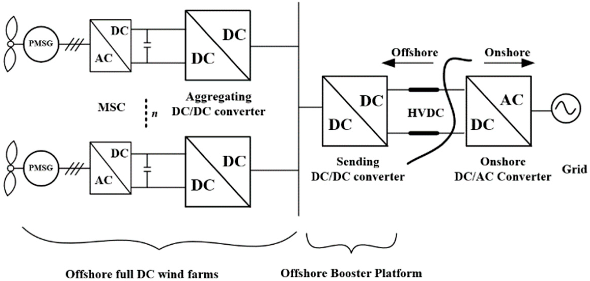
Figure 1. Full DC shunt type two-stage boost wind farm topology.
Energies 17 05071 g001
Figure 2. Structure of DC wind power system.
Energies 17 05071 g002
Figure 3. DC/DC converter topology.
Energies 17 05071 g003
Figure 4. CCM modulated signal and output ideal waveform.
Energies 17 05071 g004
Figure 5. DCM modulated signal and output ideal waveform.
Energies 17 05071 g005
Figure 6. DC/DC converter control block diagram.
Energies 17 05071 g006
Figure 7. DC-output wind turbine topology including fault handling circuitry.
Energies 17 05071 g007
Figure 8. Full DC-type two-stage booster offshore wind farms.
Energies 17 05071 g008
Figure 9. Stabilized condition related simulation waveforms. (a) Input voltage Udc, sub-converter input voltage Udc1 and Udc2, sub-converter output voltage Uo1 and Uo2. (b) Converter transmission capacity Po.
Energies 17 05071 g009
Figure 10. Voltage and current waveforms on both sides of the transformer during stable operation.
Energies 17 05071 g010
Figure 11. Simulation-related waveforms under variable operating conditions. (a) Input voltage Udc, sub-converter input voltage Udc1 and Udc2, sub-converter output voltage Uo1 and Uo2. (b) Input voltage Idc and (c) converter delivery power Po.
Energies 17 05071 g011
Figure 12. Input voltage Udc waveforms and phase shift α before and after converter failure. (a) Input voltage Udc and (b) phase shift α.
Energies 17 05071 g012
Figure 13. Real-time simulation hardware-in-the-loop experiment platform.
Energies 17 05071 g013
Figure 14. Experimental waveforms related to the converter under stabilized conditions. (a) Input voltage Udc, Udc1, and Udc2 of sub-converters. (b) Output voltage Uo1 and Uo2 of sub-converters. (c) Converter transmission capacity Po.
Energies 17 05071 g014
Figure 15. Experimental waveforms of the converter under sudden wind speed change conditions. (a) Input voltage Udc, (b) input voltage Idc, (c) sub-converter input voltage Udc1 and Udc2, (d) sub-converter output voltage Uo1 and Uo2.
Energies 17 05071 g015
Figure 16. Experimental waveforms of converter under fluctuating conditions of DC convergence network. (a) Input voltage Udc and (b) sub-converter input voltage Udc1 and Udc2.
Energies 17 05071 g016
Figure 17. Experimental waveforms of the converter under unbalanced input capacitance conditions. (a) Input voltage Udc and sub-converter input voltage Udc1 and Udc2. (b) Input current Idc.
Energies 17 05071 g017
Table 1. DC/DC converter simulation parameters.
EquipmentParameter
Rated voltage/kV6/60
Rated capacity/MW10
Input capacitance/mF10
Leakage inductance/μH20
Filter capacitor/mF2
Filter inductor/mH3
Transformer frequency/Hz1000
Transformer ratio12
Disclaimer/Publisher’s Note: The statements, opinions and data contained in all publications are solely those of the individual author(s) and contributor(s) and not of MDPI and/or the editor(s). MDPI and/or the editor(s) disclaim responsibility for any injury to people or property resulting from any ideas, methods, instructions or products referred to in the content.