Abstract
Due to its good corrosion resistance and high rigidity, fluoroplastic steel heat exchangers have become one of the main feasible solutions to the problem of flue gas waste heat recovery. Therefore, a heat transfer performance test of a fluoroplastic steel heat exchanger was carried out, and a new heat transfer correlation (Nu = 0.11Re0.72Pr0.36, 1900 < Re < 4100, Pr ≈ 0.8) of a fluid transverse tube bank suitable for smooth fluoroplastic surfaces was proposed. Comparing the results of the proposed correlation and the Zhukauskas correlation, the calculation discrepancy was decreased when using the proposed correlation, and the average discrepancy dropped from 16.8% to 3.3%. As the thickness of the fluoroplastic film was reduced, the gap between the two correlations widened. Thus, the Zhukauskas correlation was not applicable to fluoroplastic steel heat exchangers with a thin fluoroplastic film. However, the deviation between the two correlations decreased as the condensing heat transfer area increased. For the fluoroplastic steel heat exchanger with a large condensation heat transfer area, the Zhukauskas correlation could still be utilized. It was interesting to observe that the deviation between the two correlations was reduced when only flue gas condensation was present, but it showed an increasing trend with the increase in condensation intensity.
1. Introduction
In 2021, The State Council issued “Guiding Opinions of the State Council on Accelerating the Establishment and Improvement of a Green and Low-carbon Circular Development Economic System”. It was required to take the lead in making breakthroughs in energy conservation and environmental protection, clean production and clean energy, significantly increase the efficiency of energy use, continuously reduce the total emissions of major pollutants, and significantly reduce the intensity of carbon emissions [1]. But much energy in industry is released directly into the environment in the form of low-temperature waste heat. Of these, boiler flue gas is one of the main sources of low-grade waste heat. If the waste heat of flue gas can be deeply recycled, the efficiency of energy utilization will improve and carbon dioxide emissions will be reduced [2].
Therefore, a lot of research on waste heat recovery from flue gas has been carried out. Through a case study, Wang [3] found that 8316 t/a SCE and 15,300 t/a CO2 were saved for a 660 MW power plant after installing a low-pressure economizer before the FGD to recover flue gas waste heat. Meryem [4] designed a flue gas waste heat recovery unit for a 60 MW natural gas hot water boiler, and economic benefits of more than USD 400,000/year were achieved by recovering 16% of the heat from flue gas, which resulted in a fuel saving of 10.3%. A pilot test in a power plant was carried out by Xiong [5], and the results showed that the waste heat recovery heat exchanger could recover 61.6 t/h of water and 129.5 GJ/h of heat from 250,000 m3/h of flue gas. Han [6] added a steam–air heater to the bypass flue waste heat recovery system, which formed a new flue gas waste heat recovery system. Thanks to this system, the coal consumption of the 1000 MW coal-fired power plant was reduced by 4.00 g/kW·h. For a more complete utilization of the waste heat from the flue gas, Yan [7] proposed a novel cold-end optimization system, and the coal consumption was further reduced to 5.38 g/kW·h in the same 1000 MW coal-fired power plant. Therefore, as an important way of energy cascade utilization, flue gas waste heat recovery and utilization has become a key way to implement the strategic task of energy conservation and carbon reduction in the thermoelectric industry.
The tube bank heat exchanger is a commonly used heat exchange equipment in waste heat recovery systems [8,9]. However, in the process of recovering waste heat from flue gas, when the flue gas temperature is below the dew point, acidic condensate will form on the heat exchange surface, resulting in serious low-temperature corrosion [10]. In order to prevent low-temperature corrosion, conventional metal heat exchangers have strict restrictions on engineering applications; i.e., the inlet temperature of the cooling medium cannot be lower than the dew point [11,12]. Therefore, fluoroplastic with excellent corrosion resistance was proposed as the heat exchange tube material, and the fluoroplastic heat exchanger with good corrosion resistance was manufactured [13]. The pilot test results of flue gas waste heat recovery using fluoroplastic heat exchangers indicated that fluoroplastic heat exchangers could overcome the shortcomings of conventional metal heat exchangers under the acid dew point [14]. The further decrease in flue gas temperature caused more latent heat to be recovered, and the total heat transfer coefficient of the heat exchanger increased to 275 W/(m2·K).
But the use of pure fluoroplastic heat exchangers in engineering still poses many challenges [15]. Firstly, its rigidity is not enough, and the heat exchange tube is easily shaken, which could cause vibrations in the flue and endanger the operation safety. Secondly, the pressure capacity is insufficient, and using a cooling medium with higher pressure presents difficulties, significantly limiting its potential applications. For this reason, our research group proposed the use of fluoroplastic steel heat exchangers in our previous study; i.e., the heat exchanger tube was formed by using stainless steel as the base tube and injecting molding technology to apply a fluoroplastic film coating [16].
On the other hand, the primary method for recovering waste heat from flue gas is by fitting a single-stage low-temperature economizer before or after the electrostatic precipitator, and the waste heat initially released into the atmosphere is recovered by partially heating the condensate water [17,18]. Recently, Tan’s theoretical calculations [19] showed that a two-stage arrangement of heat exchangers could significantly increase the recovery of waste heat from flue gas compared to a single-stage arrangement, and the effect of energy conservation and carbon reduction was significantly improved. Under optimum conditions, the flue gas waste heat recovery system could achieve a coal saving of 4.11 g/(kW·h) for a 1000 MW coal-fired boiler, resulting in an annual net benefit of over 14.2 million USD.
Based on a cogeneration thermal system, coupled with a two-stage arrangement and a fluoroplastic steel heat exchanger, a waste heat recovery and utilization system for flue gas was suggested by our research group, which employed demineralized water as a cooling agent and a two-stage heat exchanger made of fluoroplastic steel that was arranged in series [16]. When designing fluoroplastic steel heat exchangers, it was found that there was a significant difference of 40% between the convective heat transfer coefficient calculated using the Zhukauskas correlation and the experimental value for the smooth fluoroplastic heat exchange tube [20]. However, the calculation of the convective heat transfer coefficient in the design of condensing heat exchangers was based on the conventional heat transfer correlation formula [21,22] and rarely considered the difference in the heat transfer correlation formula under different materials. Mohammadaliha [23] designed a polymer-based condensing heat exchanger with good corrosion resistance, and an experimental method was used to compare the heat transfer performance of polymer-based condensing heat exchangers with stainless steel ones. In order to analyze the influence of thermal conductivity on heat transfer performance under different materials, an analytical model was established by Mohammadaliha [24]. But the calculation process still used the conventional heat transfer correlation to calculate the convective heat transfer coefficient without taking surface roughness into account.
In summary, it is essential to solve the problem of inaccurate heat transfer correlation when designing fluoroplastic steel heat exchangers. For this purpose, the heat transfer performance test of a fluoroplastic steel heat exchanger was carried out, and a new heat transfer correlation of a fluid transverse tube bank suitable for smooth fluoroplastic surfaces was fitted. On this basis, the difference between the proposed heat transfer correlation and the Zhukauskas correlation in heat transfer performance calculation was theoretically analyzed under conditions of varying fluoroplastic film thickness, condensation intensity, and the condensation heat transfer area ratio. And then the application characteristics of the proposed heat transfer correlation for fluoroplastic steel heat exchangers were summarized. The research results provide tools and guidance for the performance calculation of fluoroplastic steel heat exchangers, and promote the application of waste heat recovery and utilization technology.
2. Testing System
2.1. Testing Setup
The test facility for the heat transfer characteristics of the fluoroplastic steel heat exchanger was the flue gas waste heat recovery and utilization system installed in a 220 t/h circulating fluidized bed boiler unit. The field layout of the flue gas waste heat recovery and utilization system of the fluoroplastic steel heat exchanger is shown in Figure 1. The first fluoroplastic steel heat exchanger, called the low-temperature economizer, was installed on the flue before the desulfurizer after the electrostatic precipitator, and the inlet flue gas temperature was over 100 °C. The second fluoroplastic steel heat exchanger, called the condenser, was installed after the desulfurizer. At this point, the inlet temperature of the cooling water was determined by the external environment, and the flue gas temperature was approximately 55 °C and the water vapor content was close to saturation.
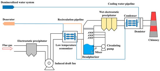
Figure 1.
Field layout of the flue gas waste heat recovery and utilization system.
In order to obtain the convective heat transfer correlation of the fluoroplastic steel heat exchanger, the heat transfer performance test was carried out for the first-stage heat exchanger. In the test, the boiler load was gradually adjusted in the range of 120–220 t/h. The flue gas produced under different loads was sent to the low-temperature economizer via the induced draft fan after the ESP. As the flue gas passed through the low-temperature economizer, it exchanged heat with the demineralized water drawn from the demineralized water system and heated by the condenser. During the heat transfer process, the flue gas was on the outside of the condenser tube and traversed the heat exchanger tube. The demineralized water flowed into the first row of heat exchange tubes through the collector, and then in a serpentine path to the rear heat exchange tube. The flow between flue gas and demineralized water was countercurrent flow. After heat transfer, the flue gas was cooled down and then entered the wet desulfurization system. At the same time, to prevent flue gas condensation, the inlet temperature of the demineralized water was kept above the dew point temperature by means of demineralized water recirculation. Under all operating conditions, it should be tested after stable operation. Detailed information about the experimental conditions is summarized in Table 1.

Table 1.
Ranges of parameters under experimental conditions.
The pressure at the inlet and outlet of the flue gas, and the temperature and flow rate at the inlet and outlet of the demineralized water, were recorded by the DCS system. The E-type thermocouples were used to measure the temperature of demineralized water, with a working range of 0–300 °C and within an error of ±12 °C. And the float flowmeter was used to measure the velocity of demineralized water, with a working range of 0.5–2.5 m/s and within an error of ±2.5%. The S-type pitot tube was used to measure the pressure of flue gas, with a working range of ±5 kPa and within an error of ±3.0%. The compositions, temperature, and flow rate of flue gas were measured using a portable flue gas analyzer (Wöhler® F550CI, Wöhler Technik GmbH, Bad Wünnenberg, Germany), and the working range of the flue gas composition (CO2, O2, SO2) was 0–15 vol.%, 0–25 vol.%, 0–0.02 vol.%, respectively; the working range of the flue gas humidity was 0–60%; the working range of the flue gas velocity was 0.1–130 m/s; and the working range of the flue gas temperature was −20 to 1300 °C. Accordingly, the measurement error of the flue gas composition (CO2, O2, SO2) was ±5.0%, the measurement error of the humidity was ±1.5%, the measurement error of velocity was ±1.0%, and the measurement error of temperature was ±6.6 °C. Prior to the desulfurizer, the flue gas had undergone denitrification treatment, so the low NOx content was negligible, and the flue gas could be simplified to a mixture of CO2, O2, SO2, N2, and H2O. Based on the measurement parameters, the measurement ranges and errors are summarized in Table 2.

Table 2.
Ranges and errors of the measurement parameters.
2.2. Fluoroplastic Steel Heat Exchanger
To compensate for the inadequacies of pure fluoroplastic heat exchangers in terms of rigidity and pressure-bearing capacity, a fluoroplastic steel heat exchanger was developed. Based on a 2205 stainless-steel tube, a 0.3 mm fluoroplastic film (PFA) was covered by injection molding technology, so as to form the fluoroplastic steel heat exchange tube. The outer diameter of the fluoroplastic steel heat exchange tube was 20.6 mm, and the wall thickness of the stainless-steel tube was 1 mm. The fluoroplastic steel heat exchange tube in the low-temperature economizer was arranged linearly, and the thermal conductivity of the stainless steel was 16.27 W/(m·K), and the thermal conductivity of the fluoroplastic was 0.209 W/(m·K). The images depicting the fluoroplastic steel low-temperature economizer can be found in Figure 2, while the relevant parameters are outlined in Table 3.
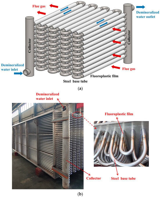
Figure 2.
Configuration of fluoroplastic steel low-temperature economizer: (a) Configuration of fluoroplastic steel low-temperature economizer; (b) Photos of fluoroplastic steel low-temperature economizer.

Table 3.
The parameters of fluoroplastic steel low-temperature economizer.
2.3. Experimental Data Processing
In the process of calculating heat transfer for a heat exchanger made of fluoroplastic steel, the heat balance formula can be applied.
where Q represents the overall heat exchange between flue gas and cooling water; qm,g and qm,c are the mass flow rate of flue gas and cooling water, respectively; Tg,in and Tg,out are the inlet and outlet temperature of the flue gas, and Tc,in and Tc,out are the inlet and outlet temperature of the cooling water; and cp,g and cp,c represent the specific heat capacity of flue gas and cooling water.
The transfer of waste heat from flue gas to cooling water involved four stages: from the flue gas to the outer wall of the heat exchange tube, from the outer wall to the middle wall of the heat exchange tube, from the middle wall to the inner wall of the heat exchange tube, and from the inner wall of the heat exchange tube to the demineralized water. The heat transfer remained constant at each point.
where , , , , represent the average temperature of the flue gas, the outer wall of the heat exchange tube, the intermediate layer, the inner wall of the heat exchange tube, and the cooling water in sequence, respectively; do, dm, di are the outer diameter of the heat exchange tube, the diameter of the intermediate layer, and the inner diameter, respectively; λP and λS are the thermal conductivity of fluoroplastic and stainless steel; kg and kc are the heat transfer coefficient of flue gas side and cooling water side; and l is the length of heat exchange tube.
The heat transfer coefficient for the cooling water side in Equation (5) was determined by employing the forced convective heat transfer correlation within the tube (Nu = 0.023Re0.8Pr0.4) [25]. The average temperature of the outer wall of the heat exchange tube can be calculated from Equations (2)–(5), and the test value of the heat transfer coefficient of the flue gas side can be obtained. Then, the heat transfer coefficient of the heat exchanger was calculated based on the outer surface of the heat exchange tube.
where k is the heat transfer coefficient of the heat exchanger.
When the condensation test of the fluoroplastic steel heat exchanger was carried out, the inlet and outlet flue gases were considered to be saturated with water vapor, and then the mass content of water vapor in the inlet and outlet flue gases was estimated as follows [26].
where psat is the saturation pressure of water vapor; pg is the flue gas pressure; Mv and Meq represent the molar mass of water vapor and the equivalent molar mass of flue gas, respectively; Td is the dew point temperature of flue gas; and w is the mass fraction.
From the mass flow rate of flue gas and the mass content of water vapor, the condensing amount of water vapor in the flue gas can be obtained.
where q′m,g and q″m,g represent the inlet and outlet mass flow rates of the flue gas, respectively; qm,v is the condensate mass flow rate of water vapor in the flue gas; and wv,in and wv,out are the inlet and outlet water vapor mass fractions.
The experimental convective heat transfer coefficient of flue gas was employed to verify the heat transfer correlation, so the uncertainty analysis of flue gas convective heat transfer coefficient outside the heat exchange tube was conducted. The formula of the convection heat transfer coefficient contains multiple independent variables. According to the function relationship and the method of root-sum-square (RSS), the relative uncertainty of the experimental convective heat transfer coefficient of flue gas can be estimated using the following formula [27].
where R is the calculated value from formulas; xi is the independent variable; and U is the uncertainty of the independent variable corresponding to the subscript.
Ignoring the uncertainties of physical properties [28], the detail of the relative uncertainty for the experimental convective heat transfer coefficient of flue gas is shown in Table 4. From the analysis results, the relative uncertainty of the experimental convective heat transfer coefficient was 6.5–7.5% under the Re range of 1913–4031.

Table 4.
Uncertainty analysis for experimental convective heat transfer coefficient of flue gas.
3. Heat Transfer Model
The heat transfer process of waste heat recovery from flue gas mainly included flue gas convective heat transfer and flue gas condensation. When the vapor partial pressure was higher than the saturation pressure corresponding to the liquid at wall temperature, the flue gas condensed on the heat exchanger wall (film condensation), including the heat and mass transfer of the flue gas to the heat exchanger wall [29,30]. The heat transfer mechanism of flue gas condensation is shown in Figure 3.
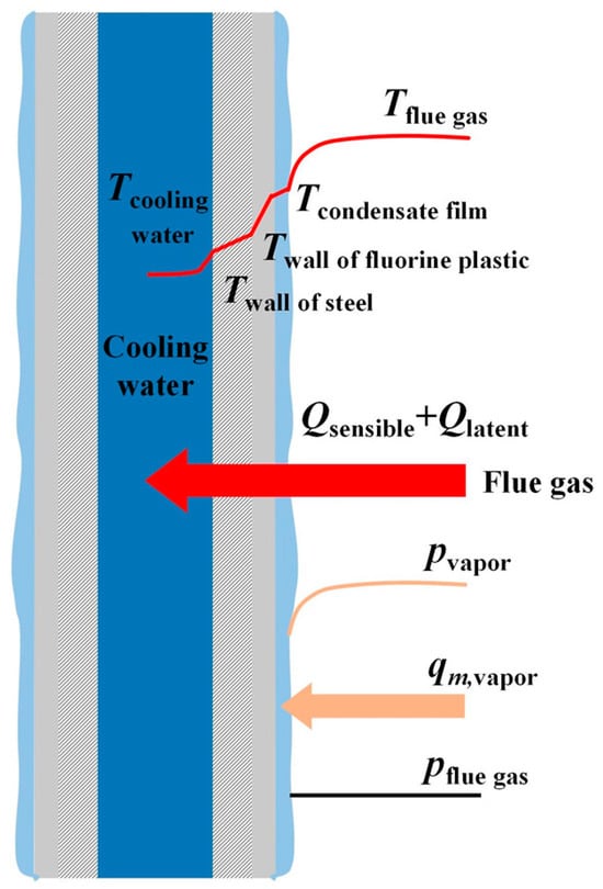
Figure 3.
Schematic diagram of the heat transfer mechanism of flue gas condensation.
According to the theory of Colburn and Hougen [31], the heat transfer of flue gas condensation was the sum of sensible heat transfer and latent heat transfer [32]. Therefore, the heat transfer of flue gas condensation was calculated using the following formula:
where Qs and Ql represent the sensible heat transfer of flue gas and the latent heat transfer of water vapor respectively; Ao is the surface area of the heat exchanger; qm,con is the mass flow rate of condensate water; lv represents the latent heat of water; hg is the convective heat transfer coefficient of flue gas; and hc is the condensation heat transfer coefficient of flue gas.
Compared to the thermal resistance of gas film, the thermal resistance of liquid film was very small, so the temperature difference between the flue gas at the condensation interface and the wall was also small. Therefore, the liquid film and its related properties were ignored, such as re-evaporation of condensate was not considered. When the flow reached a steady state, it was assumed that the partial pressure of water vapor at the wall was the saturation pressure corresponding to the wall temperature, and the latent heat released by the condensation of water vapor was completely absorbed by the cooling water. For the mass transfer process, the condensation rate was assumed to be controlled by the concentration boundary layer, and the effect of Stefan flow was ignored. The transfer rate of water vapor in the flue gas to the wall is as follows.
where and represent the average density of water vapor on the flue gas side and the outer wall, respectively; and hm is the convective mass transfer coefficient of flue gas.
The convective mass transfer coefficient in Equation (14) was obtained by the analogy between momentum, and heat and mass transfer. According to the Colburn analogy, the heat transfer factor JH and the mass transfer factor JD are given [33,34] as follows:
where u∞ is the freestream velocity; ρg is the flue gas density; cp,g is the specific heat capacity of flue gas; and Pr is the Prandtl number and Sc is the Schmidt number.
Based on the Lewis relation, there was an equivalent relation between the heat transfer factor and mass transfer factor [35], that is, JH = JD. Coupling Equations (15) and (16), the convective mass transfer coefficient can be obtained.
where the ratio of Sc/Pr was defined as the Lewis number; for the flue gas, Le ≈ 1 could be generally accepted [36].
If the flue gas did not condense, the amount of flue gas waste heat recovery was equal to the amount of flue gas convection heat transfer.
In the theoretical analysis of the application characteristics of the heat transfer correlation, the total heat transfer coefficient of the fluoroplastic steel heat exchanger can be calculated by the following formula.
where ktot is the total heat transfer coefficient; Δtm represents the logarithmic mean temperature difference in the heat exchanger.
4. Results and Discussions
4.1. Heat Transfer Correlation Fitting and Verification
According to the test results of the first fluoroplastic steel heat exchanger, and referring to the common form of convective heat transfer correlation, a new heat transfer correlation (Nu = 0.11Re0.72Pr0.36, 1900 < Re < 4100, Pr ≈ 0.8) of a fluid transverse tube bank suitable for smooth fluoroplastic surfaces was fitted. In this proposed correlation, the qualitative temperature was the average temperature of the fluid at the inlet and outlet of the tube bank, the flow velocity in the Re number was the average flow velocity at the smallest section of the tube bank, and the characteristic length was the outside diameter of the tube. And the proposed correlation was recommended to calculate the average surface heat transfer coefficient of the tube bank with the number of tube rows greater than or equal to 16 along the direction of fluid flow. Figure 4 compares the experimental value of the convective heat transfer coefficient of the flue gas side with the calculated value from the proposed heat transfer correlation. As shown in Figure 4, the experimental value of the convective heat transfer coefficient of the flue gas side was in good agreement with the calculated value from the proposed heat transfer correlation under different Reynolds numbers. The average discrepancy between them was 3.3% and the maximum discrepancy was no more than 8.0%. When using the conventional Zhukauskas correlation (Nu = 0.27Re0.63Pr0.36) [37], the calculated convective heat transfer coefficient of the flue gas side showed a large deviation (as shown in Figure 5). The average discrepancy between the experimental value and the calculated convective heat transfer coefficient was 16.8%, and the maximum discrepancy was no more than 21.4%. Compared to the Zhukauskas correlation, the proposed heat transfer correlation significantly improved the calculation accuracy of the convective heat transfer coefficient when the fluid traversed the tube bank with a smooth fluoroplastic surface, and it provided a suitable tool for the design and performance calculation of fluoroplastic steel heat exchangers. It is worth noting that the value calculated using the Zhukauskas correlation was always higher than that tested. The reason for this is that the Zhukauskas correlation was obtained from the heat transfer test of conventional steel tube heat exchangers, and the surface roughness of the conventional steel tube (0.4 μm) was much higher than the surface roughness of the fluoroplastic steel tube (0.17 μm). Under the same conditions, the coarser the heat exchange surface, the greater the additional disturbance it caused in the laminar boundary layer and the more intense the heat and mass exchange of the fluid. Therefore, the convective heat transfer intensity of the fluoroplastic steel tube with low surface roughness is lower than that of the conventional steel tube, and the convective heat transfer coefficient of the flue gas side calculated by the Zhukauskas correlation was always higher than the experimental value. This was the significance of refitting the heat transfer correlation for the fluid transverse tube bank with a smooth fluoroplastic surface.
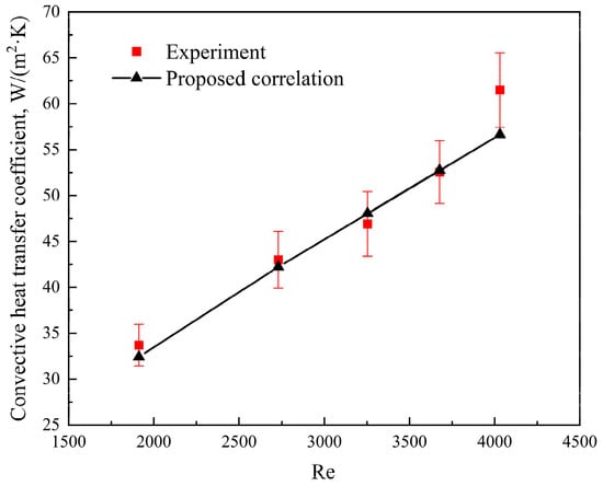
Figure 4.
Comparison of the experimental value of the convective heat transfer coefficient of the flue gas side and the calculated value from the proposed heat transfer correlation.
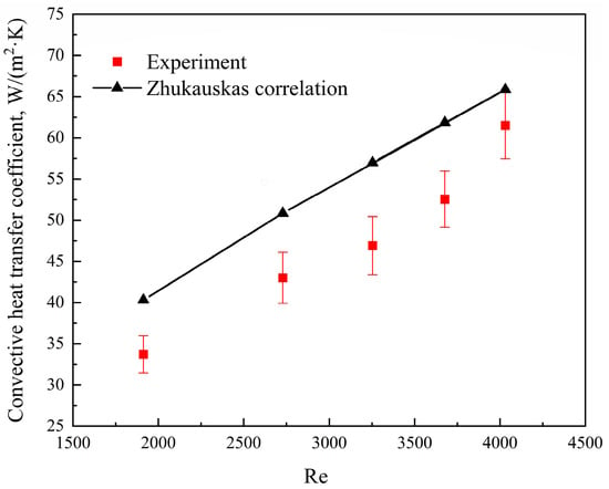
Figure 5.
Comparison of the experimental value of the convective heat transfer coefficient of the flue gas side and the calculated value from the Zhukauskas correlation [37].
4.2. Influence of Fluoroplastic Film Thickness
For a pure flue gas convective heat transfer process, the heat transfer resistance of the fluoroplastic steel heat exchanger was mainly the gas film thermal resistance on the flue gas side, the thermal resistances of the heat exchange tube and cooling water side were relatively small. Therefore, the calculation accuracy of the convective heat transfer coefficient of the flue gas side had a great influence on the total heat transfer coefficient of the fluoroplastic steel heat exchanger, which resulted in the deviation of the design and performance calculation of fluoroplastic steel heat exchangers. The fluoroplastic steel heat exchange tube was composed of fluoroplastic and stainless steel, but the thermal conductivity of fluoroplastic was much lower than that of stainless-steel material, and there was an order-of-magnitude gap between them. As a result, the thermal resistance of the heat exchange tube increased significantly with the thickening of the fluoroplastic film, and its proportion in the total thermal resistance also increased rapidly. The distribution of the proportion of each thermal resistance under different thicknesses of the fluoroplastic film is shown in Figure 6. It can be seen that the thermal resistance of the heat exchange tube was only 7.0% of the total thermal resistance when the fluoroplastic film thickness was 0.3 mm. And when the fluoroplastic film thickness was increased to 4.3 mm, the thermal resistance of the heat exchange tube accounted for 55.9% of the total thermal resistance, which became the main thermal resistance in the heat transfer process. The thermal resistance ratio of the heat exchange tube increased, while the thermal resistance ratio of the flue gas side decreased, so the thickening of the fluoroplastic film reduced the influence of the thermal resistance of the flue gas side on the total heat transfer coefficient of the fluoroplastic steel heat exchanger. Correspondingly, the influence of the calculation accuracy of the convective heat transfer coefficient on the total heat transfer coefficient of the fluoroplastic steel heat exchanger was also weakened. The total heat transfer coefficients of the fluoroplastic steel heat exchanger were calculated according to the convective heat transfer coefficients obtained by the Zhukauskas correlation and the proposed heat transfer correlation, respectively. The trends of the two total heat transfer coefficients and the deviation between them under the different fluoroplastic film thicknesses are shown in Figure 7. It was found that with the increase in fluoroplastic film thicknesses, the difference between the total heat transfer coefficients based on the Zhukauskas correlation and the proposed heat transfer correlation was gradually reduced. When the fluoroplastic film thickness was 0.3 mm, the deviation between the Zhukauskas correlation and the proposed correlation was as high as 16.1%, and when the fluoroplastic film thickness was increased to 4.3 mm, the deviation between the Zhukauskas correlation and the proposed correlation was reduced to 7.0%.

Figure 6.
Distribution of the proportion of each thermal resistance under different thicknesses of fluoroplastic film.
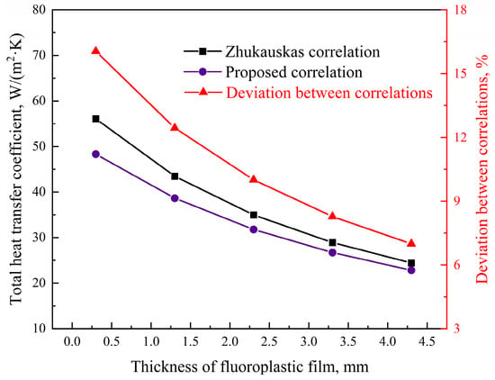
Figure 7.
Total heat transfer coefficients based on the Zhukauskas correlation [37] and the proposed heat transfer correlation, and the deviation between them under the different fluoroplastic film thicknesses.
In addition, the increase in fluoroplastic film thickness led to the increase in total heat exchange resistance of the fluoroplastic steel heat exchanger, so the total heat transfer coefficient was decreased. Therefore, with the increase in fluoroplastic film thickness, the total heat transfer coefficient of the fluoroplastic steel heat exchanger based on the Zhukauskas correlation and the proposed heat transfer correlation had a downward trend, decreasing from 56.1 W/(m2·K) and 48.3 W/(m2·K) to 24.4 W/(m2·K) and 22.8 W/(m2·K), respectively.
4.3. Influence of Condensation Intensity
When the cooling water temperature was lower than the dew point temperature of the flue gas, the heat exchange that occurred in the fluoroplastic steel heat exchanger was a process of flue gas condensation, i.e., the operating state of the condenser. During the process of flue gas condensation, there was not only convective heat transfer of flue gas but also the condensation heat transfer of water vapor. Compared to the convective heat transfer part of flue gas, the latent heat released by water vapor condensation was much higher than the convective heat. Therefore, in the process of flue gas condensation, the overall heat transfer coefficient of the flue gas side was significantly improved. Figure 8 shows the various heat transfer coefficients of the flue gas side at different cooling water inlet temperatures. As shown in Figure 8, the heat transfer coefficient of condensation was much higher than that of convection, and the overall heat transfer coefficient of the flue gas side was significantly improved by the water vapor condensation. At these conditions, the proportion of flue gas side thermal resistance in the total thermal resistance decreased, and the influence of the calculation accuracy of the convective heat transfer coefficient on the total heat transfer coefficient of the fluoroplastic steel heat exchanger was weakened. Therefore, the deviation between the total heat transfer coefficient based on the Zhukauskas correlation and that based on the proposed correlation was reduced compared to the pure flue gas convective heat transfer process, and the deviation was reduced from 16.1% to 10.5%.
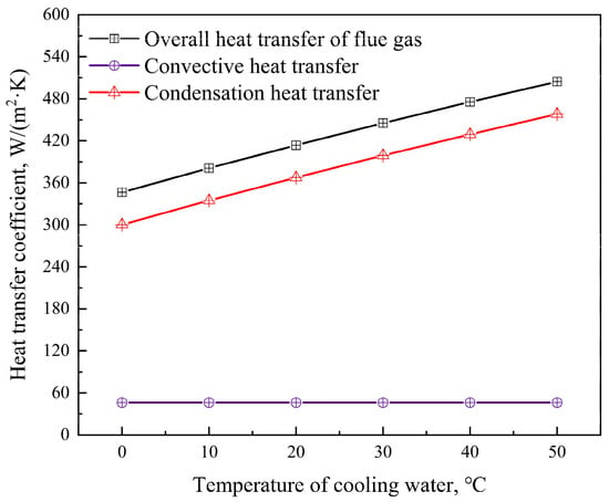
Figure 8.
Various heat transfer coefficients of the flue gas side at different cooling water inlet temperatures.
However, the total heat transfer coefficient of the fluoroplastic steel heat exchanger showed a decreasing trend with the increase in condensation intensity. This was because the lower the inlet temperature of the cooling water, the greater the degree of subcooling and the greater the condensation strength. On the other hand, the lower the inlet temperature of the cooling water, the greater the heat transfer temperature difference. Under this condition, the growth rate of heat transfer was less than the growth rate of heat transfer temperature difference as the condensation intensity increased. According to the heat transfer equation (Q = kAΔtm), the heat transfer temperature difference was inversely proportional to the heat transfer coefficient, so the heat transfer coefficient of the flue gas side decreased gradually with the increase in condensation intensity. Due to the decrease in the heat transfer coefficient of the flue gas side, the proportion of flue gas side thermal resistance in the total thermal resistance increased with the increase in condensation intensity. Therefore, with the increase in condensation intensity, the influence of the calculation accuracy of the heat transfer coefficient of the flue gas side on the total heat transfer coefficient was enhanced, and then the deviation between the total heat transfer coefficient based on the Zhukauskas correlation and that based on the proposed correlation also increased. The variation trend of the two total heat transfer coefficients and the deviation between them at different cooling water inlet temperatures are shown in Figure 9. However, with the increase in condensation intensity, the calculation deviation of the total heat transfer coefficient increased less, by only 3.4%.
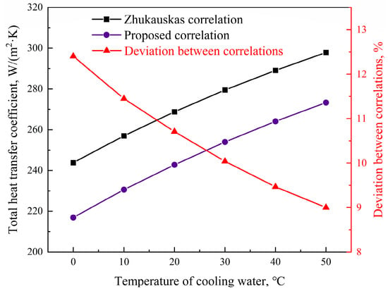
Figure 9.
Total heat transfer coefficients based on the Zhukauskas correlation [37] and the proposed heat transfer correlation, and the deviation between them at different cooling water inlet temperatures.
4.4. Influence of Condensation Heat Transfer Area Ratio
Unlike the pure flue gas condensation in the condenser, the cooling water temperature was not always kept below the dew point temperature of flue gas in the low-temperature economizer. Therefore, the low-temperature economizer not only had the flue gas condensation part, but it also included the flue gas convective heat transfer part. According to the above analysis, when the flue gas condensation occurred, the proportion of flue gas side thermal resistance in the total thermal resistance decreased, and then the influence of the calculation accuracy of the convective heat transfer coefficient of the flue gas side on the total heat transfer coefficient increased. For this reason, the calculation difference between the Zhukauskas correlation and the proposed correlation was investigated when the area ratio of the flue gas convective heat transfer and flue gas condensation heat transfer was different.
The total heat transfer coefficients of the fluoroplastic steel heat exchanger were calculated according to the convective heat transfer coefficients obtained by the Zhukauskas correlation and the proposed correlation, respectively. The trends of the two total heat transfer coefficients and the deviation between them under different condensation heat transfer area ratios are shown in Figure 10. As shown in Figure 10, when the proportion of flue gas condensation heat transfer area increased from 0 to 31.4%, the deviation between the Zhukauskas correlation and the proposed correlation decreased from 13.5% to 4.4%. Therefore, the deviation between the Zhukauskas correlation and the proposed correlation decreased rapidly with the increase in the proportion of the flue gas condensation heat transfer area. The reasons for the above trend were as follows: with the increase in the proportion of flue gas condensation heat transfer area, the heat transfer coefficient of the flue gas side gradually increased, while the proportion of flue gas side thermal resistance in the total thermal resistance gradually decreased, as shown in Figure 11. When the proportion of flue gas side thermal resistance in the total thermal resistance decreased, the influence of the calculation accuracy of the convective heat transfer coefficient of the flue gas side on the total heat transfer coefficient of the fluoroplastic steel heat exchanger was weakened.
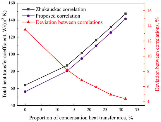
Figure 10.
Total heat transfer coefficients based on the Zhukauskas correlation [37] and the proposed correlation, and the deviation between them under different condensation heat transfer area ratios.
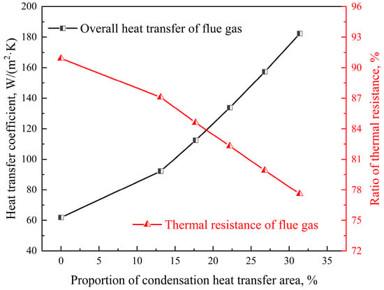
Figure 11.
Heat transfer coefficient of the flue gas side and the flue gas side thermal resistance under different condensation heat transfer area ratios.
In contrast to the trend of the calculation deviation, the intensity of flue gas heat transfer gradually increased with the increase in the proportion of the flue gas condensation heat transfer area, and the total heat transfer coefficient of the fluoroplastic steel heat exchanger also increased. When the proportion of the flue gas condensation heat transfer area increased from 0 to 31.4%, the total heat transfer coefficient of the fluoroplastic steel heat exchanger increased from 56.3 W/(m2·K) to 141.5 W/(m2·K).
5. Conclusions
In order to obtain a new heat transfer correlation of a fluid transverse tube bank suitable for smooth fluoroplastic surfaces, a test of convective heat transfer was carried out by the fluoroplastic steel heat exchanger in the flue gas waste heat recovery system of a 220 t/h circulating fluidized bed boiler unit. According to the test results, and referring to the common form of the convective heat transfer correlation, a new heat transfer correlation (Nu = 0.11Re0.72Pr0.36, 1900 < Re < 4100, Pr ≈ 0.8) of a fluid transverse tube bank suitable for smooth fluoroplastic surfaces was fitted, and it was recommended to calculate the average surface heat transfer coefficient of the tube bank with the number of tube rows greater than or equal to 16 along the direction of fluid flow. The proposed heat transfer correlation and the Zhukauskas correlation were then used to calculate the convective heat transfer coefficient of the flue gas side, and they were compared with the experimental value of the convective heat transfer coefficient of the flue gas side. The results showed that the calculation discrepancy of the proposed correlation was significantly reduced compared to the Zhukauskas correlation, and the average discrepancy dropped from 16.8% to 3.3%. The proposed heat transfer correlation effectively solved the heat transfer calculation problem of the fluid transverse tube bank with a smooth fluoroplastic surface.
Based on the proposed heat transfer correlation, the difference between the proposed heat transfer correlation and the Zhukauskas correlation in the heat transfer calculation under the conditions of different fluoroplastic film thickness, condensation intensity, and condensation heat transfer area ratio was analyzed theoretically. When the fluoroplastic film thickness decreased, the discrepancy between the total heat transfer coefficient based on the Zhukauskas correlation and that based on the proposed heat transfer correlation gradually increased. Therefore, the Zhukauskas correlation was not suitable for fluoroplastic steel heat exchangers with a thin fluoroplastic film, and the proposed heat transfer correlation should be used in the design calculation. However, the deviation between the Zhukauskas correlation and the proposed heat transfer correlation decreased as the condensation heat transfer area in the fluoroplastic steel heat exchanger increased. So, the Zhukauskas correlation could still be used for the heat transfer calculation when the fluoroplastic steel heat exchanger had a relatively large condensation heat transfer area. It was interesting to note that when there was only flue gas condensation in the fluoroplastic steel heat exchanger, the deviation between the Zhukauskas correlation and the proposed heat transfer correlation was reduced. However, the deviation between the Zhukauskas correlation and the proposed heat transfer correlation showed an increasing trend with the increase in condensation intensity. Therefore, it is still not recommended to use the Zhukauskas correlation to calculate the heat transfer of fluoroplastic steel condensers with a low inlet temperature of the cooling medium.
In conclusion, this paper improved the heat transfer correlation for a fluid transverse tube bank with smooth fluoroplastic surfaces and summarized the application characteristics of the proposed heat transfer correlation, providing tools and guidance for the design and performance calculation of fluoroplastic steel heat exchangers, and promoting the application of waste heat recovery and utilization technology.
Author Contributions
Conceptualization, K.L.; methodology, Z.M.; validation, Q.W.; investigation, K.L.; resources, K.L.; data curation, K.L.; writing—original draft preparation, K.L.; writing—review and editing, Y.W.; visualization, K.L.; supervision, X.G.; project administration, H.F. All authors have read and agreed to the published version of the manuscript.
Funding
This research was funded by the Jiaxing Science and Technology Project, grant number 2023AD40001.
Data Availability Statement
The original contributions presented in the study are included in the article, further inquiries can be directed to the corresponding author.
Conflicts of Interest
Authors Kai Li, Zhihao Meng, Hong Feng, Yihong Wang and Qi Wang were employed by the company Jiaxing New Jies Thermal Power Co., Ltd. The remaining author declares that the research was conducted in the absence of any commercial or financial relationships that could be construed as a potential conflict of interest.
References
- The State Council of the People’s Republic of China, Guiding Opinions of the State Council on Accelerating the Establishment and Improvement of a Green and Low-carbon Circular Development Economic System. 2021; (In Chinese). Available online: https://www.gov.cn/zhengce/content/2021-02/22/gcontent_5588274.htm (accessed on 19 November 2023).
- Li, X.; Zhou, T.; Chen, H.; Zhang, H. Study on heat transfer performance using ceramic membrane to recover moisture and waste heat from flue gas. Appl. Therm. Eng. 2023, 231, 120887. [Google Scholar] [CrossRef]
- Wang, C.; He, B.; Sun, S.; Wu, Y.; Yan, N.; Yan, L.; Pei, X. Application of a low pressure economizer for waste heat recovery from the exhaust flue gas in a 600 MW power plant. Energy 2012, 48, 196–202. [Google Scholar] [CrossRef]
- Terhan, M.; Comakli, K. Design and economic analysis of a flue gas condenser to recover latent heat from exhaust flue gas. Appl. Therm. Eng. 2016, 100, 1007–1015. [Google Scholar] [CrossRef]
- Xiong, Y.; Niu, Y.; Wang, X.; Tan, H. Pilot study on in-depth water saving and heat recovery from tail flue gas in lignite-fired power plant. Energy Procedia 2014, 61, 2558–2561. [Google Scholar] [CrossRef]
- Han, Y.; Xu, G.; Zheng, Q.; Xu, C.; Hu, Y.; Yang, Y.; Lei, J. New heat integration system with bypass flue based on the rational utilization of low-rade extraction steam in a coal–fired power plant. Appl. Therm. Eng. 2017, 113, 460–471. [Google Scholar] [CrossRef]
- Yan, M.; Zhang, L.; Shi, Y.; Zhang, L.; Li, Y.; Ma, C. A novel boiler cold-end optimisation system based on bypass flue in coal-fired power plants: Heat recovery from wet flue gas. Energy 2018, 152, 84–94. [Google Scholar] [CrossRef]
- Liu, J.; Zhu, F.; Ma, X. Industrial application of a deep purification technology for flue gas involving phase-transition agglomeration and dehumidification. Engineering 2018, 4, 416–420. [Google Scholar] [CrossRef]
- Li, K.; Wang, E.; Li, D.; Husnain, N.; Fareed, S. Numerical and experimental investigation on water vapor condensation in turbulent flue gas. Appl. Therm. Eng. 2019, 160, 114009. [Google Scholar] [CrossRef]
- Zhao, S.; Yan, S.; Wang, D.K.; Wei, Y.; Qi, H.; Wu, T.; Feron, P.H. Feron, Simultaneous heat and water recovery from flue gas by membrane condensation: Experimental investigation. Appl. Therm. Eng. 2017, 113, 843–850. [Google Scholar] [CrossRef]
- Klemes, J.J.; Arsenyeva, O.; Kapustenko, P.; Tovazhnyanskyy, L. Compact Heat Exchangers for Energy Transfer Intensifification: Low Grade Heat and Fouling Mitigation; CRC Press: Boca Raton, FL, USA, 2015. [Google Scholar]
- Ma, H.; Liang, N.; Liu, Y.; Luo, X.; Hou, C.; Wamg, G. Experimental study on novel waste heat recovery system for sulfide-containing flue gas. Energy 2021, 227, 120479. [Google Scholar] [CrossRef]
- Cao, R.; Tan, H.; Xiong, Y.; Mikulčić, H.; Vujanović, M.; Wang, X.; Duić, N. Improving the removal of particles and trace elements from coal-fired power plants by combining a wet phase transition agglomerator with wet electrostatic precipitator. J. Clean. Prod. 2017, 161, 1459–1465. [Google Scholar] [CrossRef]
- Xiong, Y.; Tan, H.; Wang, Y.; Xu, W.; Mikulčić, H.; Duić, N. Pilot-scale study on water and latent heat recovery from flue gas using fluorine plastic heat exchangers. J. Clean. Prod. 2017, 161, 1416–1422. [Google Scholar] [CrossRef]
- Yang, J.; Sun, Z.; Yuan, R.; Huang, H.; Hu, Y. Study of heat transfer and ash deposit characteristics of fluoroplastic steel air-preheater in power plant. J. Zhejiang Univ. (Eng. Sci.) 2018, 52, 577–583. (In Chinese) [Google Scholar]
- Li, K.; Zhang, P.; Gong, J.; Wu, B.; Tan, Q. Practice and analysis of flue gas waste heat recovery system in co-generation plant. J. Shanghai Univ. Electr. Power 2021, 67, 533–538. (In Chinese) [Google Scholar]
- Jin, Y.; Gao, N.; Zhu, T. Techno-economic analysis on a new conceptual design of waste heat recovery for boiler exhaust flue gas of coal-fired power plants. Energ. Convers. Manag. 2019, 200, 112097. [Google Scholar] [CrossRef]
- Xu, G.; Xu, C.; Yang, Y.; Fang, Y.; Li, Y.; Song, X. A novel flue gas waste heat recovery system for coal-fired ultra-supercritical power plants. Appl. Therm. Eng. 2014, 67, 240–249. [Google Scholar] [CrossRef]
- Tan, H.; Cao, R.; Wang, S.; Wang, Y.; Deng, S.; Duić, N. Proposal and techno-economic analysis of a novel system for waste heat recovery and water saving in coal-fired power plants: A case study. J. Clean. Prod. 2020, 281, 124372. [Google Scholar] [CrossRef]
- Xu, G.; Chen, Y.; Niu, C.; Man, X.; Wang, Y.; Ren, Y.; Xu, G. Optimization of heat transfer model and performance analysis of fluorine plastic heat exchangers. Proc. CSEE 2017, 37, 2297–2304. (In Chinese) [Google Scholar] [CrossRef]
- Jeong, K.; Kessen, M.J.; Bilirgen, H.; Levy, E.K. Analytical modeling of water condensation in condensing heat exchanger. Int. J. Heat Mass Tran. 2010, 53, 2361–2368. [Google Scholar] [CrossRef]
- Macháčková, A.; Kocich, R.; Bojko, M.; Kunčická, L.; Polko, K. Numerical and experimental investigation of flue gases heat recovery via condensing heat exchanger. Int. J. Heat Mass Tran. 2018, 124, 1321–1333. [Google Scholar] [CrossRef]
- Mohammadaliha, N.; Amani, M.; Bahrami, M. Thermal performance of heat and water recovery systems: Role of condensing heat exchanger material. Clean. Eng. Technol. 2020, 1, 100024. [Google Scholar] [CrossRef]
- Mohammadaliha, N.; Amani, M.; Bahrami, M. A Thermal-hydraulic assessment of condensing tube bank heat exchangers for heat and water recovery from flue gas. Appl. Therm. Eng. 2022, 215, 118976. [Google Scholar] [CrossRef]
- Yang, S.; Tao, W. Heat Transfer; Higher Education Press: Beijing, China, 2006; pp. 246–261. (In Chinese) [Google Scholar]
- Shen, D.W.; Jiang, Z.M.; Tong, J.G. Engineering Thermodynamics; Higher Education Press: Beijing, China, 2007; p. 379. (In Chinese) [Google Scholar]
- Moffat, R.J. Describing the uncertainties in experimental results. Exp. Therm. Fluid Sci. 1988, 1, 3–17. [Google Scholar] [CrossRef]
- Wang, E.; Li, K.; Mao, J.; Husnain, N.; Li, D.; Wu, W. Experimental study of flow and heat transfer in rotary air preheaters with honeycomb ceramics and metal corrugated plates. Appl. Therm. Eng. 2018, 130, 1549–1557. [Google Scholar] [CrossRef]
- Zschaeck, G.; Frank, T.; Burns, A.D. CFD modelling and validation of wall condensation in the presence of non-condensable gases. Nucl. Eng. Des. 2014, 279, 137–146. [Google Scholar] [CrossRef]
- Han, L.; Yang, K.; Yang, J.; Li, R.; Li, Y.; Deng, L.; Che, D. A thermal calculation model for tubular condensing heat exchanger. Appl. Therm. Eng. 2024, 244, 122701. [Google Scholar] [CrossRef]
- Colburn, A.P.; Hougen, O.A. Design of cooler condensers for mixtures of vapors with noncondensing gases. Ind. Eng. Chem. 1934, 26, 1178–1182. [Google Scholar] [CrossRef]
- Li, J.; Saraireh, M.; Thorpe, G. Condensation of vapor in the presence of noncondensable gas in condensers. Int. J. Heat Mass Tran. 2011, 54, 4078–4089. [Google Scholar] [CrossRef]
- Colburn, A.P. A method of correlating forced convection heat-transfer data and a comparison with fluid friction. Int. J. Heat Mass Tran. 1964, 7, 1359–1384. [Google Scholar] [CrossRef]
- Chilton, T.H.; Colburn, A.P. Mass transfer (absorption) coefficients prediction from data on heat transfer and fluid friction. Ind. Eng. Chem. 1934, 26, 1183–1187. [Google Scholar] [CrossRef]
- Jeong, K.; Levy, E.K. Theoretical prediction of sulfuric acid condensation rates in boiler flue gas. Int. J. Heat Mass Tran. 2012, 55, 8010–8019. [Google Scholar] [CrossRef]
- Lian, Z. Principle of Heat and Mass Exchange with Equipment; China Architecture & Building Press: Beijing, China, 2006; pp. 58–60. (In Chinese) [Google Scholar]
- Žukauskas, A. Heat Transfer from Tubes in Crossflow. Adv. Heat Transf. 1972, 8, 93–160. [Google Scholar]
Disclaimer/Publisher’s Note: The statements, opinions and data contained in all publications are solely those of the individual author(s) and contributor(s) and not of MDPI and/or the editor(s). MDPI and/or the editor(s) disclaim responsibility for any injury to people or property resulting from any ideas, methods, instructions or products referred to in the content. |
© 2024 by the authors. Licensee MDPI, Basel, Switzerland. This article is an open access article distributed under the terms and conditions of the Creative Commons Attribution (CC BY) license (https://creativecommons.org/licenses/by/4.0/).