Abstract
This paper introduces a robust proportional integral derivative higher-order sliding mode controller (PID-HOSMC) based on a double power reaching law (DPRL) to enhance large-signal stability in DC microgrids. The microgrid integrates a solar photovoltaic (SPV) system, an energy storage system (ESS), and DC loads. Efficient DC-DC converters, including bidirectional and boost converters, are employed to maintain a constant voltage level despite the lower SPV output power. An artificial neural network (ANN) generates the optimal reference voltage for the SPV system. The dynamical model, which incorporates external disturbances, is initially developed and based on this model, and the PID-HOSMC is designed to control output power by generating switching gate pulses. Afterwards, Lyapunov stability theory is used to demonstrate the model’s closed-loop stability, and theoretical analysis indicates that the controller can converge tracking errors to zero within a finite time frame. Finally, a comparative numerical simulation result is presented, demonstrating that the proposed controller exhibits a 58% improvement in settling time and an 82% improvement in overshoot compared to the existing controller. Experimental validation using processor-in-the-loop (PIL) confirms the proposed controller’s performance on a real-time platform.
1. Introduction
1.1. Background and Challenges
Wind power, solar photovoltaics (SPVs), fuel cells, and other distributed generators (DGs) are becoming increasingly popular choices to meet growing energy demands, reduce fossil fuel consumption, and tackle global climate change concerns [1]. However, it is always advisable to operate renewable energy sources (RESs) at high-efficiency levels due to the potentially high installation costs associated with RESs [2]. In this context, numerous studies recommend establishing microgrids, which are local grid systems comprising DGs, loads (both DC and AC), and energy storage systems (ESSs) to ensure high power reliability and efficiency [3]. Microgrid systems can be classified as either DC microgrids or AC microgrids, depending on the type of common bus voltage. However, DC microgrids are gaining preference over AC microgrids due to their ease of integrating RESs, which enhances flexibility and reliability [4]. Furthermore, controlling a DC microgrid is simpler than controlling an AC microgrid, as managing reactive power flows and frequency control are not significant challenges in a DC microgrid [4].
DC microgrids, despite its numerous advantages, face various technical and operational challenges that need resolution before they can gain widespread acceptance [5]. One of these challenges stems from the inherent variability in solar irradiance, leading to fluctuations in the output power of SPV systems. Therefore, ensuring a continuous power supply to the load becomes challenging due to the fluctuating DC-bus voltage. On the other hand, maintaining a consistent voltage is vital for preserving power balance. This challenge can be effectively addressed by integrating an ESS into the DC bus, where the ESS plays a pivotal role. When there is insufficient power from RESs to meet the load’s demands, the ESS supplements the power. Conversely, when there is surplus power surpassing the load requirements, the ESS stores the excess energy [6]. To fulfill this control objective, an ESS-integrated bidirectional DC-DC converter, capable of operating in either boost or buck mode depending on the DC-bus voltage status, is proposed. However, the inclusion of a DC-DC boost converter and a DC-DC bidirectional converter adds complexity and nonlinearity to microgrids. Therefore, implementing a controller becomes indispensable to ensure the smooth operation of a DC microgrid.
1.2. Literature Review
In [7], a multilevel converter was introduced that utilized an optimization approach to the energy management of a battery ESS (BESS)-based single-phase hybrid SPV distributed system. Though this converter effectively achieved its control objectives, its layered structure posed practical implementation challenges. To address this limitation, an alternative approach was presented in [8], involving the connection of the DC-bus to a BESS through a dual-active-based converter. However, though this method offers relative ease of construction, it did come with certain limitations when applied in DC microgrid applications. Droop control, extensively discussed in references [9,10], serves as an efficient control method to keep a constant DC-bus voltage while assuring equitable load sharing within microgrids. However, droop controllers have a drawback in that they can compromise the accuracy of load current sharing as result of voltage drop effects caused by line impedance. This issue was tackled by a fuzzy logic gain-scheduling controller, as referenced in [11,12]. Furthermore, another fuzzy logic control strategy was proposed in [13] to oversee the voltage of the DC-bus and equalize power distribution between loads and generators. However, one potential limitation of this approach is its potential inadequacy in representing the system’s dynamics, often due to the absence of dynamical models in the controller’s design methodology. Moreover, the controllers mentioned above were typically designed based on linearized models. Consequently, they may fall short of delivering the desired control performance when operating conditions change, as noted in [14]. In contrast, the DC microgrid, due to the presence of multiple power electronics converters, is inherently complex and nonlinear. Hence, there is a growing interest in exploring nonlinear control schemes to ensure consistent performance under diverse operating conditions.
A widely used nonlinear controller, the model predictive controller (MPC), is utilized to minimize a cost function and generate control signals for converters [15,16]. In [17], an MPC scheme was proposed to address the impact of pulse loads in a DC microgrid. Another MPC strategy was presented in [18] for improving the the DC microgrid’s stability. However, the practicality of this control technique is limited by issues, such as parameter accuracy and time-consuming optimization computations. To overcome this constraint, an alternative solution is offered by the nonlinear feedback linearization controller (FBLC), known for its successful application in DC microgrid scenarios. In [19], an FBLC approach was introduced for regulating DC-bus voltage while maintaining power balance within the DC microgrid. Additionally, Ref. [20] presented an adaptive FBLC, which employed adaptation laws to predict undisclosed parameters and ensure proper power distribution within the microgrid. However, though these control strategies contribute to improving the stability of DC-bus voltage, the precision of system factors plays a significant role in achieving the desired control objectives. In practical applications, obtaining accurate system parameter information can be challenging due to the rapid changes of parameters with variations in the operating conditions. Furthermore, this control approach often negates valuable nonlinear factors that have the potential to enhance the system’s transient stability. Therefore, switching to nonlinear backstepping control, instead of FBLC schemes, can lead to improved transient responses in the system without having exact parameter knowledge [21].
In [22], a nonlinear backstepping controller (BSC) was suggested to assess the dynamic stability of hybrid DC microgrids under varying conditions. Simulation results indicated successful voltage control and precise power balance. An adaptive version of the BSC was presented in [23] to improve power-sharing performance and maintain DC-bus voltage regulation, particularly when system parameters are unknown. However, practical limitations emerge due to the necessity for the derivative of virtual control at each step, particularly in the context of higher-order systems. Additionally, achieving satisfactory performance with this control method is contingent on accurately tuning user-defined gain levels, which introduces an additional layer of complexity [14,22].
As discussed in [24,25,26,27], nonlinear sliding mode controllers (SMCs) present effective solutions to overcome the limitations of BSC and FBLC schemes. An SMC was suggested in [28,29] to manage power flow in both directions between microgrid components and the DC-bus. However, these controllers required precise circuit parameters and might not handle system uncertainties well. In response to this limitation, an adaptive SMC was proposed in [30,31] to enhance the system’s resilience to parameter uncertainties. However, chattering remains an issue in practical applications, stemming from high-frequency fluctuations near the sliding surface. Recent solutions to the chattering problem include nonsingular fast terminal (NSFT) SMCs [32], super-twisting SMCs [33,34,35,36], and reaching law-based solutions [37,38,39,40]. Among these, the switching law-based approach, focusing on the reaching phase of SMC techniques, appears promising for effectively addressing the chattering problem. Based on the above discussion, a comparative analysis of various control techniques is presented in Table 1.
Table 1.
Analyzing and comparing various control techniques.
1.3. Motivation, Contributions, and Layout of This Paper
Taking into account the various limitations of previous approaches, this research aims to propose a novel solution that can not only enhance the stability of the DC-bus voltage but also facilitate the equitable distribution of power within the microgrid. To the author’s knowledge, this approach represents a novel advancement, as it has hitherto remained unexplored in the context of DC microgrid applications, where the twin challenges of the enhancement of DC-bus voltage and power balance maintenance converge. This endeavor hinges on the establishment of a comprehensive mathematical model for each microgrid component, underpinned by the employment of the proposed control technique, which generates a robust control signal. The utilization of the Lyapunov function theorem further ensures the closed-loop stability of the microgrid. Now, in comparison to existing methodologies, the contributions of this research can be succinctly summarized as follows:
- A novel ANN-MPPT-based PID-HOSMC approach is proposed for a PV-dominant DC microgrid, designed using the nonlinear model with external disturbances and integrating a DPRL to effectively address the chattering issues inherent in conventional SMC methods.
- Theoretical analysis demonstrates that the proposed controller’s convergence time is significantly less than traditional reaching law-based SMC methods. Additionally, a method for selecting the sliding surface coefficients is also presented.
- Simulation analysis and PIL results demonstrate the robustness of the PID-HOSMC in comparison to an existing SMC approach under sudden changes in load demands and solar irradiance.
These contributions collectively advance the state of the art in microgrid control and have the potential to significantly impact the field’s development and practical applications.
The remainder of this paper is structured as follows: In Section 2, an overview of the proposed DC microgrid, elucidating its various operating modes is presented. Section 3 is dedicated to developing dynamic models, shedding light on their behavior, interactions, and problem formulation. In Section 4, a comprehensive exploration of the design steps involved in crafting the proposed controller is presented. In Section 5, the numerical simulation results are presented, and a comparative analysis is undertaken to offer a deeper understanding of the outcomes. Finally, in Section 6, the discourse is brought to a conclusion, encapsulating the key insights and findings while also delving into the prospects for future research endeavors.
2. Overview on the Proposed DC Microgrid
In this section, a comprehensive explanation of the structure and the diverse operational modes of the proposed DC microgrids are presented.
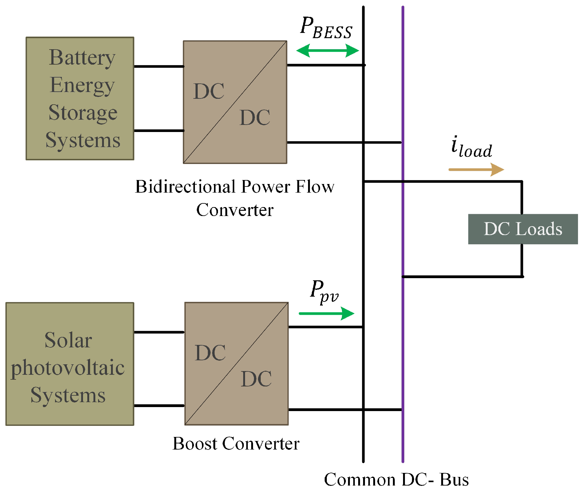
2.1. Configuration and System Description
Figure 1 illustrates the overall configuration of the proposed DC microgrid. This DC microgrid is comprised of essential components, including the SPV system, a BESS, and various DC loads, all intricately connected to the DC-bus via specialized converters. The SPV system assumes the central role as the primary power source, and its integration with the DC microgrid’s DC bus is efficiently facilitated by a dedicated DC-to-DC boost converter (DDBC). In order to maintain power equilibrium and ensure optimal operation of the DC microgrid, a BESS is seamlessly integrated, and it is integrated with a DC-DC bidirectional power flow converter (DDBPFC).
Figure 1.
Schematic representation of the proposed DC microgrid.
The DC microgrid’s net power, in accordance with its operational principles, can be mathematically expressed as follows:
In the above equation, each variable represents the following essential roles:
- symbolizes the net power of the system, representing the overall balance between power generation and power consumption.
- denotes the power output from the SPV system, serving as the primary power generation source.
- represents the power output from the BESS, which plays a crucial role in stabilizing the system and supplementing power as needed.
- stands for the power consumed by the various DC loads within the microgrid.
It is important to emphasize that the maintenance of a constant and steady-state DC-bus voltage is a critical requirement to achieve power balance between the power generation and loads. To ensure this requirement, the dynamic behavior of the DC-bus voltage must hold to the following relationship:
In Equation (2), the variable C represents the DC-bus capacitor. From Equation (2), it is obvious that when the DC-bus voltage remains constant, the net power in the system effectively balances power generation and consumption, resulting in a net power of zero. This state of equilibrium ensures that the microgrid operates efficiently. However, any surplus or deficit in power generation compared to power consumption leads to changes in the DC-bus voltage, which can be detrimental to the microgrid’s stability. In such scenarios, it becomes necessary to regulate the power flow from the BESS to maintain a constant DC-bus voltage. Therefore, this control action is crucial to ensure the stable operation of the microgrid. In the following, the operational modes of the DC microgrid are presented, with a particular focus on power balancing strategies.
2.2. Operational Modes
To ensure power balance within the DC microgrid under a range of operational conditions, it is vital to control the output power of each microgrid component, as mentioned earlier. This study focuses on two fundamental operating modes that have been developed to achieve this control objective. These operating modes are comprehensively explored in the following discussion.
Mode 1: In this specific operational mode, the SPV operates at a capacity that exceeds the cumulative demand of the total load, resulting in a surplus of generated power. This surplus prompts the need for a strategic approach in managing the excess energy efficiently. The effectiveness of this management is intricately tied to the current state of charge (SoC) of the battery within the system. The operational dynamics in this nuanced scenario are contingent on the responsiveness and status of the battery’s SoC. When the battery’s charge level permits it, the surplus power generated by the PV panel is intentionally directed towards the BESS. This directional flow is facilitated through the implementation of the buck mode of the converter—a specialized operation designed to efficiently channel the excess power into the BESS. The control operation within this mode can be elucidated through a stepwise process, providing a comprehensive understanding of the intricate mechanisms governing the dynamics of energy management. Hence, the expression for the charging power of the BESS can be formulated as follows:
Here, the negative sign of the battery current signifies that the battery is charging in the buck mode. Therefore, the net power in this mode can be expressed by the following equation:
Mode 2: This operational mode becomes active when the total load demand surpasses the power output generated by the SPV system. Under these circumstances, if the battery’s SoC is above the predefined minimum threshold, and the deficit between the aggregate load requirement and the SPV output power falls within the rated capacity of the battery, the BESS is deployed to fill the power gap. The control operation in this mode is detailed as follows:
Here, the positive sign of the battery current signifies that the battery is discharging in the boost mode. Therefore, the net power in this mode can be expressed by the following equation:
To precisely achieve the aforementioned operations, it is crucial to accurately control the output power of each microgrid component. Therefore, this necessitates a well-established dynamical model upon which the controller can be designed. Consequently, the following section delves into the development of the dynamical model for each unit of the DC microgrid.
3. Dynamical Modeling and Problem Formulation
In this section, a comprehensive model of DC microgrid units is developed, taking into account their unique features and constraints. Moreover, details on the model’s development along with the problem formulation are presented in the following subsections.
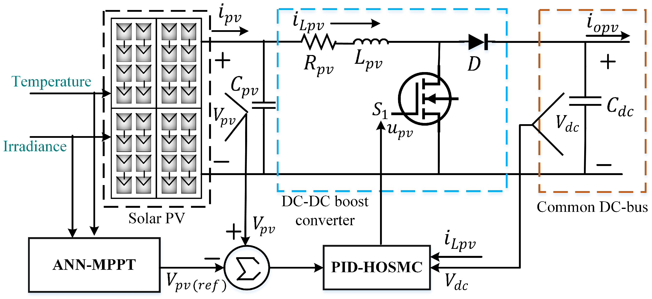
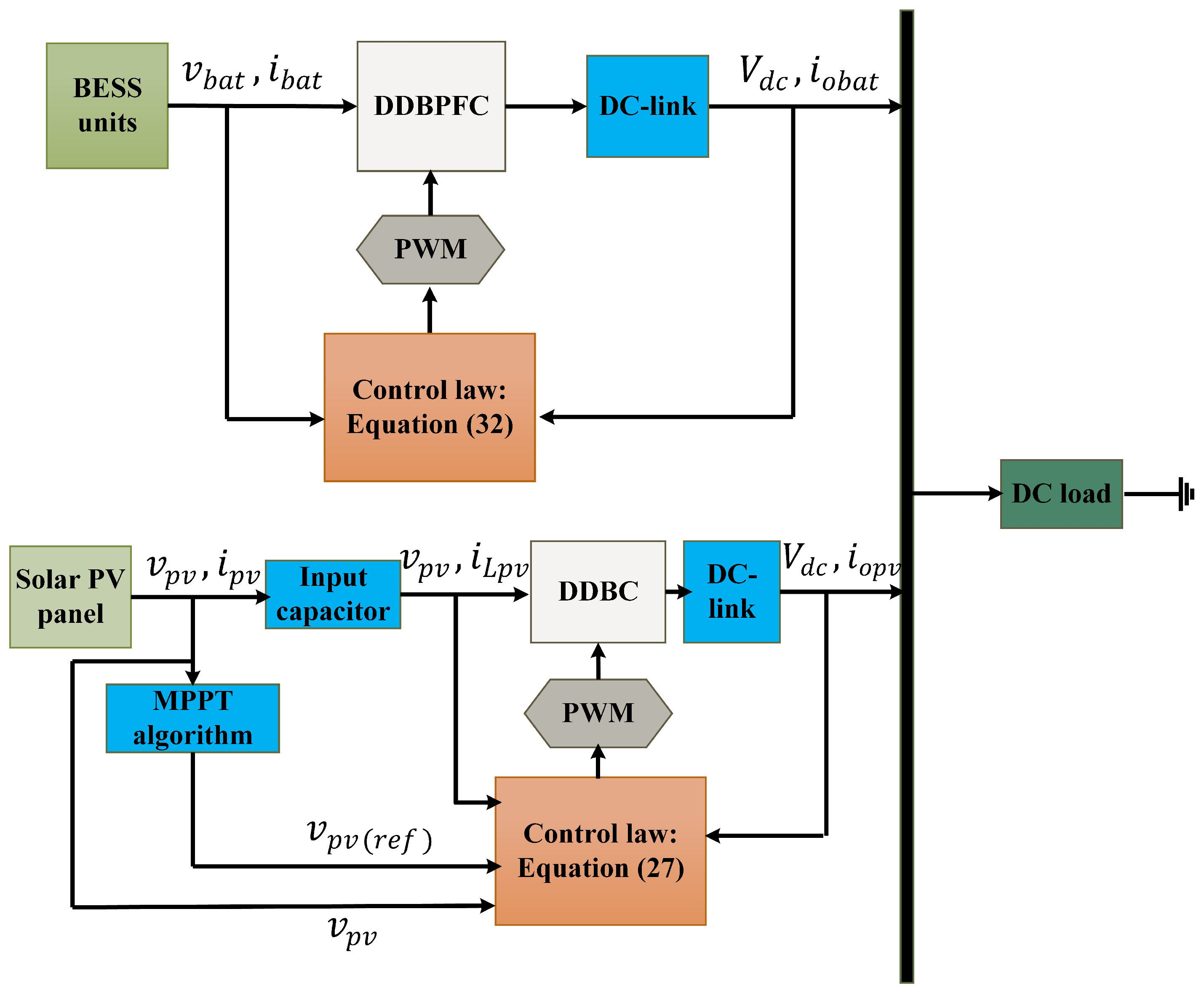
3.1. Modeling of a PV Unit with a DDBC
Figure 2 illustrates a schematic representation of a DDBC with the SPV system. The DDBC is integrated with the SPV system to match the output voltage with the DC-bus, as the output voltage is typically lower than the DC-bus voltage where the load is connected. To gain a comprehensive understanding of the system’s dynamics, Kirchhoff’s principles are applied to the components shown in Figure 2. This analysis leads to the establishment of the following dynamical model:
Figure 2.
Schematic diagram of SPV unit with a DDBC.
All the symbols’ definitions in the above equation can be found in [20].
3.2. Modeling of a BESS Unit with a DDBPFC
The schematic circuit diagram of the BESS, incorporating a DDBPFC, is presented in Figure 3. To derive the dynamical model, Kirchhoff’s principles are applied to the components depicted in Figure 3. Hence, this analysis establishes the following dynamical model:
Figure 3.
BESS unit incorporation of a DDBPFC.
The symbols in the above equation have their useful meanings, which are defined in [20].
3.3. Problem Formulation
All physical systems, in reality, exhibit both external and internal uncertainties. So, the proposed microgrid will encounter various uncertainties and complexities in practice. Therefore, this paper specifically focuses on external disturbances to demonstrate the robustness of the proposed control approach. By taking into account external disturbances, Equation (5) can be represented as:
where , , and are external disturbances.
Similarly, by incorporating external disturbances, Equation (6) can be expressed as follows:
where and are external disturbances.
To guarantee the successful and reliable operation of the DC microgrid, it is crucial to implement an efficient control strategy. Therefore, each microgrid unit is equipped with a nonlinear DPRL-based PID-HOSMC approach to acquire the necessary control input, which is presented in the following section.
4. Proposed PID-HOSMC Design
As previously discussed, a DC microgrid inherently exhibits high levels of nonlinearity. Moreover, real-world applications involve significant variations in the working point due to changing solar irradiation and load demands. In response to these challenges, this work introduces a nonlinear PID-SMC approach to ensure the stability of the DC microgrid. The following subsections outline the design steps of this proposed control approach, which aims to derive the control law for each unit within the microgrid. This approach is pivotal in addressing the complexities and fluctuations inherent in the DC microgrid.
4.1. PID-HOSMC Design for the Solar PV and BESS Units
In this section, the design procedure of a PID-HOSMC for the SPV and BESS units is outlined, with the goal of achieving the desired outcomes. The process commences with an examination of the selection of a suitable sliding surface, ensuring stability and dynamic performance. Following this, an explanation is provided regarding the control of the reaching phase, which involves incorporating an appropriate reaching algorithm to minimize chattering and maximize reaching time.
In order to design the proposed PID-HOSMC, which utilizes a DPRL, the following requirement must be satisfied:
where represents the sliding surface. To obtain the control signal while ensuring , the following steps are crucial.
Step 1: In light of the design criteria, the SPV output voltage tracking error is defined as follows:
where is the PV reference voltage, which will be obtained using an artificial neural network (ANN) algorithm. The derivative of along with the first equation of (7) is as follows:
In Equation (11), is the stabilizing function for stabilizing . To achieve this objective, we choose the Lyapunov control function (LCF) as follows:
Using Equation (11), the derivative of yields
At this point, the virtual control law of the stabilizing function, is selected as follows:
where is the user-defined constant. Now, combining Equations (13) and (14), yields
with . From Equation (15), it is obvious that will be negative-definite or semi-definite if the following condition is satisfied
Step 2: In this step, the tracking error between and can be defined as follows:
The derivative of can be expressed as:
where , , and . Now, the dynamic of Equation (18) can be expressed as:
At this stage, in terms of tracking errors, the PID-based sliding surface is chosen as follows:
where is a positive constant with . It should be emphasized that the chattering must be reduced while the finite time convergence is accelerated for better overall performance. To attain that control objective, a constant rate reaching law (CRRL), as described in [37], can be used construct the control law which fulfills :
where is the switching constant. Now, the reaching time for from Equation (21) can be obtained as follows:
where is the initial value of the sliding surface. It is obvious from Equation (22) that is inversely proportional to the convergence time. Hence, a faster convergence time depends on a higher value of , consequently increasing the chattering, which is not desirable. To overcome this limitation and increase system robustness while lowering chattering and offering a shorter reaching time, a DPRL is proposed in this work, which is presented as follows:
where , , , and . According to Equation (23), the reaching law will vary depending on the conditions of and . Hence, the DPRL guarantees rapid reaching, and the controller exhibits exceptional transient and dynamic characteristics during the reaching phase. Now, the derivative of Equation (20) can be expressed as follows:
Now, the control input from Equation (26) without external disturbances can be chosen as follows:
Remark 1.
From Equation (27), it can be seen that the control signal corresponds to the system is the first derivative. Consequently, to implement this control signal, an integrator will be incorporated into the system. The integrator will play a vital role in transforming the control signal into a more gradual and continuous form, thereby alleviating the issue of chattering often stemming from abrupt or discontinuous control inputs. In this way, the proposed controller significantly contributes to the improvement in system performance and the mitigation of the chattering problem.
At this point, the dynamic of the sliding surface can be written as:
where .
Assumption 1.
It is assumed that the lumped disturbances and its derivative are bounded, i.e., and , where and are known positive constants.
In this step, it is necessary to check the stability of the DDBC. To check this stability, the LCF is defined as follows:
Using Equation (23), the derivative of Equation (29) is expressed as follows:
with . Under Assumption 1, Equation (30) can be rewritten as follows:
Since , the SPV unit’s incorporation of the converter is stable.
To avoid repetition, the detailed design approach is not presented for the BESS unit, as it has already been discussed for the SPV unit. Therefore, the control law using the same approach as described above can be expressed as follows:
where , , and are positive constant parameters; , is the reference value of and can be calculated as with a proportional gain , ; and is the sliding surface.
Assumption 2.
For the BESS, it is also assumed that the lumped disturbances and its derivative are also bounded, i.e., and , where and are known positive constants.
4.2. Analysis of Convergence
Under the assumption of , the individual convergence times for and for are calculated first to obtain the total convergence time in this subsection.
First case: When , by ignoring the second term, Equation (23) can be rewritten as follows:
After some mathematical manipulation, Equation (33) can be rewritten as:
The required time can now be computed from Equation (34) as follows:
Second case: Similarly, when , the required time can be calculated as follows:
Total convergence time: The total convergence time, using Equations (35) and (36), can be expressed as follows:
According to Equation (37), the error value will reach to zero in the finite time using the proposed controller. Furthermore, the proposed DPRL reduces the convergence time while preserving the same gain. Therefore, it is noticeable that the developed controller can reduce chattering while maintaining the same gain, which is a major improvement over traditional reaching laws.
4.3. Determination of Sliding Surface Coefficients
It is widely understood that the intended performance of the proposed controller would be dependent on the right selection of the sliding coefficients, which will also assure the system’s dynamic stability. Therefore, these sliding surface coefficients are computed in this subsection. To calculate these coefficients, the sliding surface must be set to zero, i.e.,
From Equation (38), it can be written as:
This is an example of a second-order linear differential equation. The usual second-order linear system equation is
By comparing Equations (38) and (39), the parameters of Equation (20) can be expressed as and . Generally, the controller response bandwidth needs to be greater than the converter cut-off frequency , so
Using the value of , Equation (40) can be written as follows:
If the damping ratio of the system is designed as , then and the value of depends on the system steady-state response. The sliding surface coefficient values can also be chosen using the same method. Hence, the computation is omitted from this work. The next part presents simulation and experiment results to illustrate the utility of the proposed controller in a DC microgrid.
5. Controller Performance Evaluation
5.1. Test System Description
Figure 1 illustrates the proposed DC microgrid system, which is simulated in the MATLAB 2022b/Simulink environment to assess the effectiveness of the desired control approach. The DC-bus features a nominal voltage of 120 V, and the capacitor value is set at 1 mF. The solar PV system is designed to provide a maximum output power of 10 kW under normal weather conditions, while the highest expected load power is 15 kW. The BESS is a lithium-ion battery with a capacity of 150 Ah and a voltage of 48 V DC. During the simulation, each converter operates with a switching frequency of 5 kHz and a sampling frequency of 10 kHz.
The designed controller’s implementation block diagram is depicted in Figure 4. It is evident that the implementation of the controller is straightforward, despite the involvement of complex computations in the design process. Moreover, it is observed that the proposed law consistently integrates the measures of the desired outputs to generate the actual control signal. Finally, the control signal is transmitted to the converters of the BESS and SPV units through their respective pulse-width modulators (PWMs).
Figure 4.
Controller’s implementation block diagram.
Detailed parameters of the DC microgrid are provided in Table 2, and the control parameters of the proposed control algorithm can be found in Table 3.
Table 2.
Nominal parameters of the test system.
Table 3.
Proposed controller’s control parameters.
Remark 2.
The parameters listed in Table 2 have been chosen to meet the specific requirements of the test system. Conversely, Table 3 outlines the specific criteria for parameter selection discussed in Section 4.3, along with their corresponding values, to ensure rapid convergence and robust control performance. This guidance aims to assist control engineers in adeptly adjusting the PID-SMC’s parameters to optimize performance in real-world scenarios. Typically, larger values for these parameters result in a faster convergence rate; however, they also lead to a more significant induced control signal. Therefore, it is essential to carefully weigh the trade-off between the system’s output response and parameter selection, as excessively large parameters may result in control signal saturation. Consequently, the parameter values presented in Table 3 have been manually tuned using a trial-and-error approach to strike a balance between the system’s output response and the associated control signal.
Remark 3.
An important emphasis is placed on using an ANN algorithm instead of traditional maximum power point tracking (MPPT) algorithms to generate the PV reference voltage. This approach optimizes power extraction from the PV array, enabling it to adapt varying solar conditions, including temperature and irradiance fluctuations. Parameters such as voltage and current from PV arrays and environmental data like irradiance and temperature or their combined effects can serve as inputs to the ANN. In this paper, training data are generated by simulating the PV array, considering parameters such as solar irradiance and temperature, in the Matlab/Simulink environment. The neural network architecture comprises three key layers: the input layer, the hidden layer, and the output layer; a total of six neurons are used during the training process.
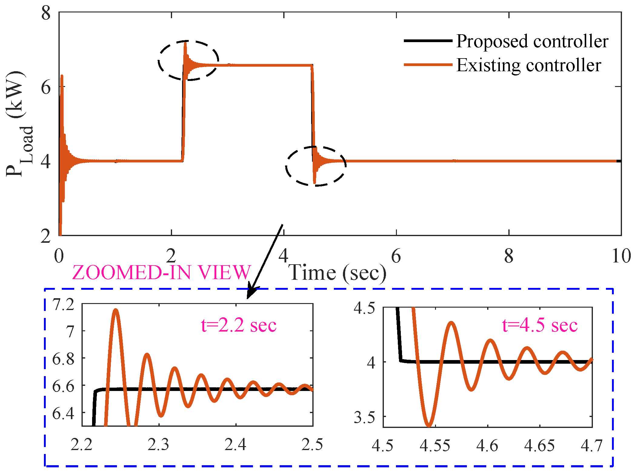
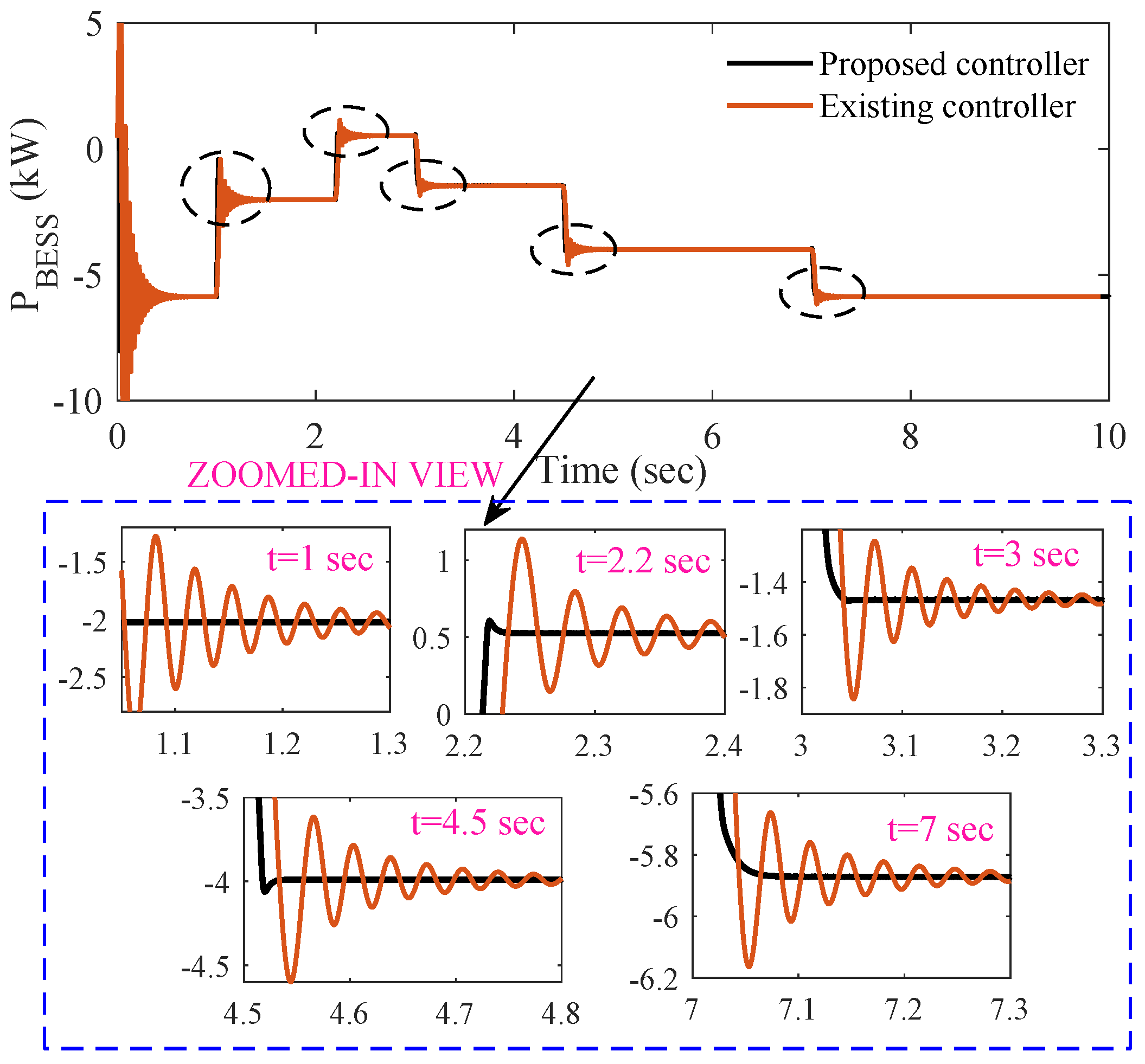
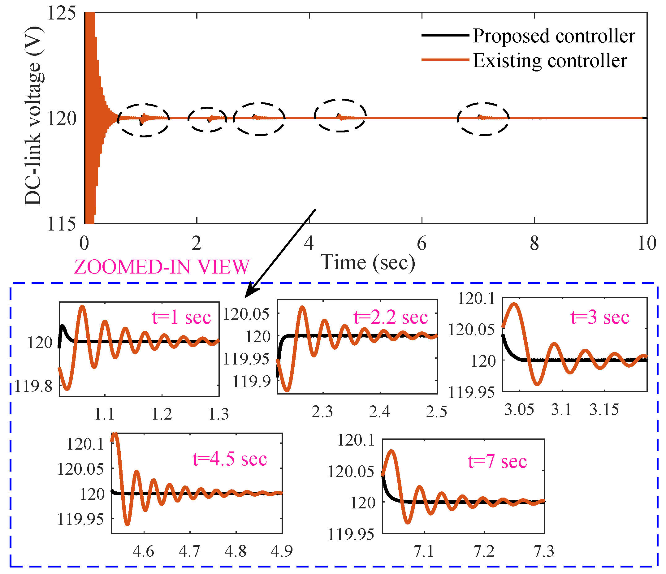
5.2. Simulation Results
The SPV unit and BESS are controlled using the designed DPRL-based PID-HOSMC. This controller plays a pivotal role in maintaining the microgrid’s power balance. When there is a shortage of power during microgrid operation, the battery steps in with the necessary power to meet the load demand, ensuring continuous and stable operation. Conversely, during times of reduced load demand, the battery efficiently absorbs any surplus power generated by the microgrid, thus optimizing energy utilization. To initiate the microgrid’s operation and establish the DC-bus voltage, a specific sequence is followed. First, the SPV system is activated, followed by the load and the BESS. This sequence ensures a smooth start and robust control over the microgrid’s power distribution and voltage levels. To assess the efficacy of this control strategy in delivering power to loads and regulating the DC-bus voltage, a series of operating scenarios are meticulously simulated. These scenarios test the system under various conditions and challenges to evaluate its overall performance. Furthermore, a comparative analysis is conducted to show the superiority of the proposed PID-HOSMC over an existing SMC technique, as proposed in [33]. This analysis highlights the advantages and effectiveness of the PID-SMC approach in optimizing the microgrid’s performance and power management.
During the initial period, from s to s, when the SPV system operates under typical atmospheric conditions, it generates an output power of kW. However, the total load demand during this first interval is only kW. In such situations, the surplus power generated by the SPV system is stored in the battery through the buck mode, taking into account the SoC of the battery. The responses of the system during these scenarios are depicted in Figure 5, Figure 6, Figure 7 and Figure 8. Figure 8 illustrates the stability of the DC-bus voltage, showing that its value remains constant at the reference level, except when there are changes in the operating conditions of the DC microgrid. However, when compared to the existing controller, it is evident that the proposed PID-HOSMC more effectively manages these transient conditions, ensuring the stability of the DC-bus voltage even in the face of changing circumstances.
Figure 5.
Dynamic response of the SPV power generation.
Figure 6.
Dynamic response of the DC load demand.
Figure 7.
Dynamic response of the BESS power.
Figure 8.
Dynamic stability of the DC-bus voltage.
Under consistent conditions with all other variables remaining unchanged, the SPV output experiences a decline from to kW at s. The corresponding response can be seen in Figure 7, which illustrates the decrease in the BESS’s charging power as the overall generation decreases. However, a pivotal shift occurs at s when the load power surges from to kW. At this point, the generated power falls significantly short of the load demand. Consequently, the battery switches to its boost mode, as evident in Figure 7, and starts to release power to maintain a power balance. This proactive response ensures that the microgrid continues to meet the increased demand without compromising its stability.
At s, the SPV system returns to its regular operation, with the load demand reduced to 4 kW from the previous kW. To ensure the power balance in this altered scenario, the battery must switch to its boost mode, during which it is actively charging. The dynamic shifts in the microgrid’s operational parameters over the simulation period introduce significant transient responses in both the power and DC-bus voltage, as illustrated in Figure 5, Figure 6, Figure 7 and Figure 8. However, it is worth noting that the PID-HOSMC excels in these dynamic conditions, effectively outperforming the existing SMC method. It successfully sustains the stability of the DC microgrid even amidst these fluctuations, ensuring consistent and reliable operation.
In addition, a detailed performance comparison between the proposed PID-HOSMC and an existing SMC approach is also conducted. This evaluation focuses on two key metrics which are extensively covered in this section: the percentage of overshoot and the settling time under various operating conditions. The comparative results are presented in Table 4, Table 5, Table 6 and Table 7, where each table specifies the settling time and percentage of overshoot for different components of DC microgrids during distinct transient periods. From these tables, it can be seen that the proposed controller shows a 58% improvement in settling time and a 82% improvement in overshoot compared to the existing controller.
Table 4.
Quantitative results of the PV panel.
Table 5.
Quantitative results of the DC load.
Table 6.
Quantitative results of the BESS.
Table 7.
Quantitative results of the DC-bus voltage.
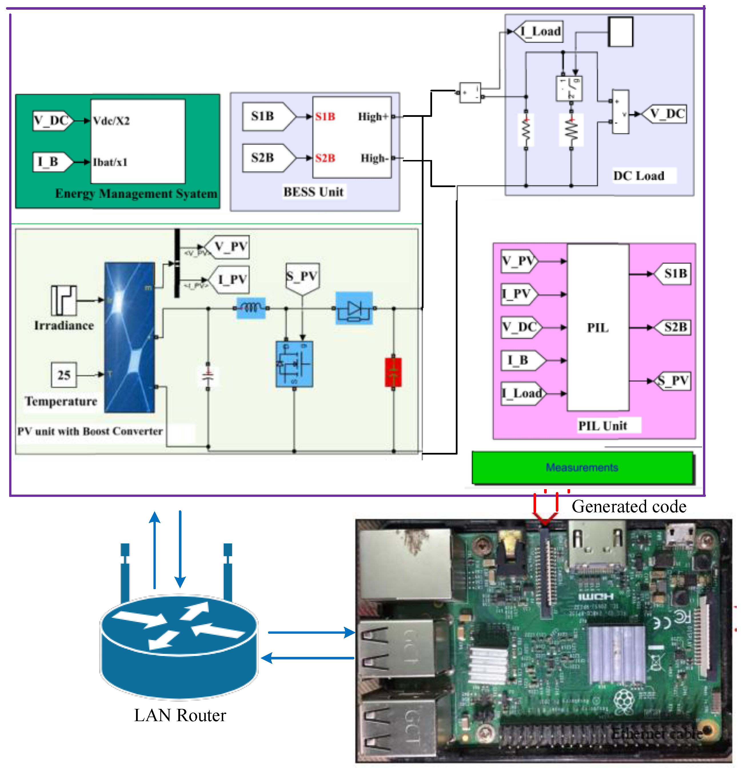
5.3. Experimental Results in PIL
The processor-in-the-loop (PIL) serves as an experimental platform to further validate the simulated results of the proposed controller. It utilizes a Rasberry Pi 3B quad-core 64-bit microprocessor (Raspberry Pi Ltd., Cambridge, UK) development board to generate control signals for driving the converter switches. Simultaneously, the MATLAB/Simulink platform functions as the physical system. The computer takes on the responsibility of analyzing all data and generating the actual control signals for each converter on the development board. Once the control signal has been processed on the microprocessor development board, the control inputs are transmitted back to the MATLAB/Simulink platform through a PIL block, as depicted in Figure 9. The switching pulse generator then converts this signal into an analog signal. As illustrated in Figure 9, data are exchanged between MATLAB/Simulink and the development board via an Ethernet connection. It is worth noting that the parameters used in this experiment match those employed in the previous simulations. In the following analysis, the performance of the controller is evaluated under varying load demands and fluctuations in SPV unit power generation.
Figure 9.
Proposed DC microgrid implementations in the PIL platform.
In the initial stage of the experiment, it is assumed that the SPV unit is operating under standard conditions, generating an output of 10.3 kW from to s, and there is a load demand of 3.13 kW until s. These conditions are illustrated in Figure 10 and Figure 11.
Figure 10.
Dynamic results in PIL platform of the SPV system.
Figure 11.
Dynamic results in PIL platform of the DC load demand.
As indicated in Figure 10 and Figure 11, there is an excess of 7.17 kW of power, which is stored in the BESS due to its SoC being below the maximum SoC limit.
At s, there is a sudden shift in solar insolation, leading to a rapid decrease in the SPV output power from 10.30 to 7.26 kW. On the other hand, all other units within the microgrid maintain their operating conditions during this period, and this change in power output persists until s. This transition is visually depicted in Figure 12. The consequence of this shift in power generation is the reduction in charging power for the BESS, as indicated in Figure 12, in response to the overall decrease in power generation. However, at s, there is a substantial increase in load demand, surging from 3.13 to 12.72 kW. The combined power responses highlight that, at this point, the total power generation is insufficient to meet the total load demand, creating a power deficit. Consequently, the BESS enters a discharge phase to ensure power balance, as illustrated in Figure 12. Then, at s, due to improved atmospheric conditions, the SPV unit’s power output experiences a significant increase, soaring from 7.259 to 9.33 kW. Nevertheless, even with this rise in power generation, the overall power generation within the DC microgrid system remains lower than the total load demand. To maintain power balance, the battery continues to discharge, as clearly demonstrated in Figure 12.
Figure 12.
Dynamic results in PIL platform of the BESS.
At s, there is a reduction in load demand, decreasing from 5.703 to 3.13 kW. With this change, the total power generation now exceeds the total load consumption. Consequently, the BESS shifts into a charging mode to store excess energy to keep the DC microgrid system balanced. However, at s, the SPV system returns to its regular operation, even though the load demand remains unchanged. In this scenario, the BESS utilizes the excess power generated by the SPV system to continue charging, ensuring that the DC microgrid system maintains a balanced power distribution. These responses clearly demonstrate the superior power balancing achieved by the proposed controller when compared to the existing controller, as evidenced by the stable DC-bus voltage response shown in Figure 13.
Figure 13.
Dynamic result in PIL platform of the DC-bus voltage.
The PIL results showcased above shed light on the dynamic nature of the microgrid’s operational points. These findings reveal that the microgrid experiences frequent changes in its operating conditions, resulting in notable transients in both the power responses and the DC-bus voltage, as depicted in Figure 10, Figure 11, Figure 12 and Figure 13. However, when we delve deeper into the assessment, specifically in terms of settling time and overshoot, it becomes abundantly clear that the controller we have designed outperforms the existing controller. It excels in effectively managing the transient stability of the DC microgrid, ensuring smoother transitions and minimizing overshoot, which are crucial factors in maintaining the reliability and robustness of the microgrid system.
6. Conclusions
In this work, a nonlinear PID-HOSMC based on a DPRL is developed. The primary objective of this controller is to maintain the voltage in the DC microgrid at a constant level, thus enabling efficient power sharing. The theoretical foundation of the designed PID-HOSMC is established through a control Lyapunov function analysis. To assess the effectiveness of the PID-HOSMC scheme, extensive evaluations are conducted under various operational scenarios, including situations with fluctuating solar irradiance and load demand fluctuations. The simulation results unequivocally demonstrate that the developed PID-HOSMC system excels at ensuring rapid transient and dynamic stability across a range of DC microgrid operational conditions. Furthermore, the theoretical and simulation results are also substantiated through experimental testing on a processor-in-loop platform. This experimental verification reaffirms the effectiveness of the proposed controller under the wide operating regime of a practical DC microgrid. The key findings of this research are summarized below:
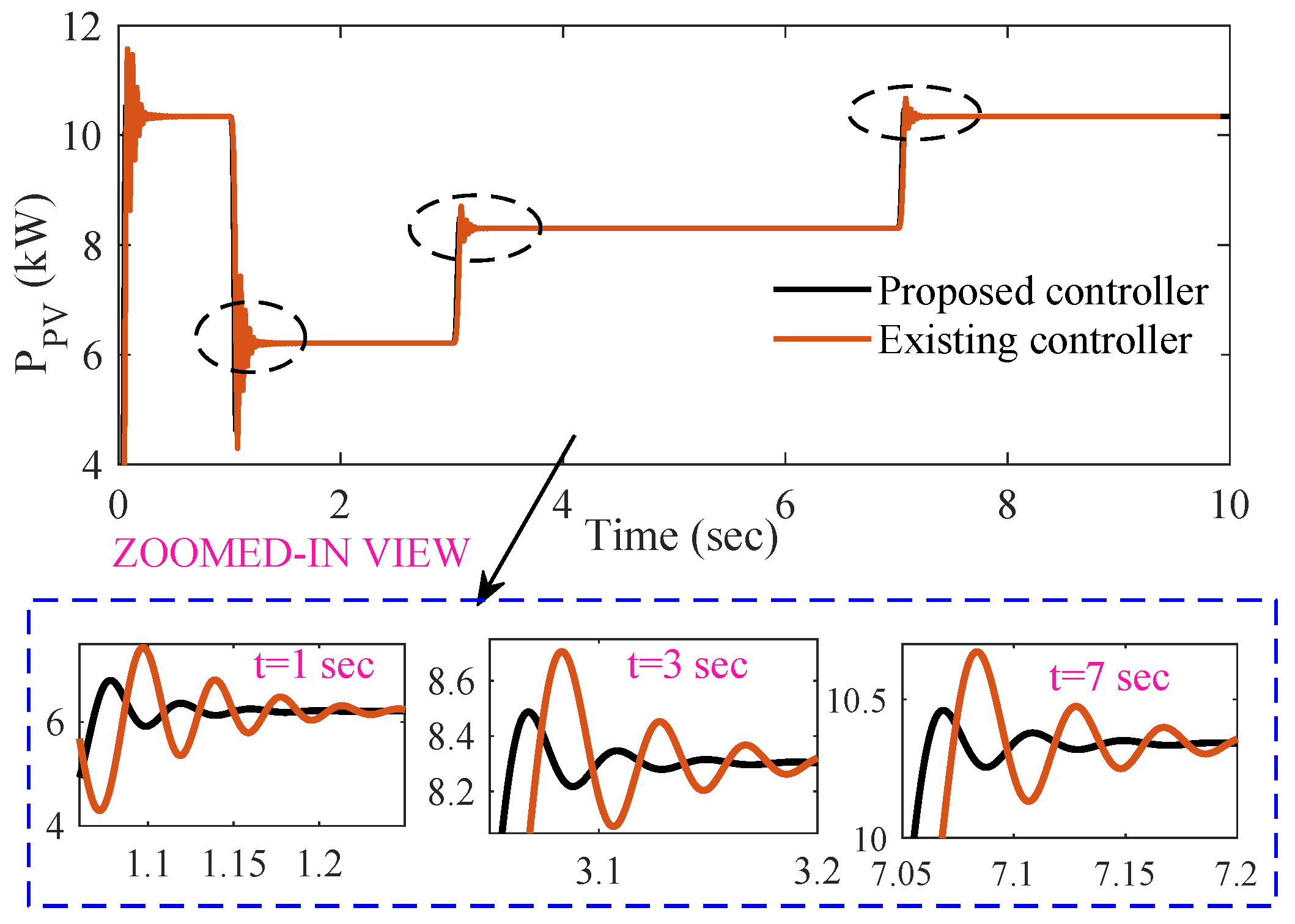
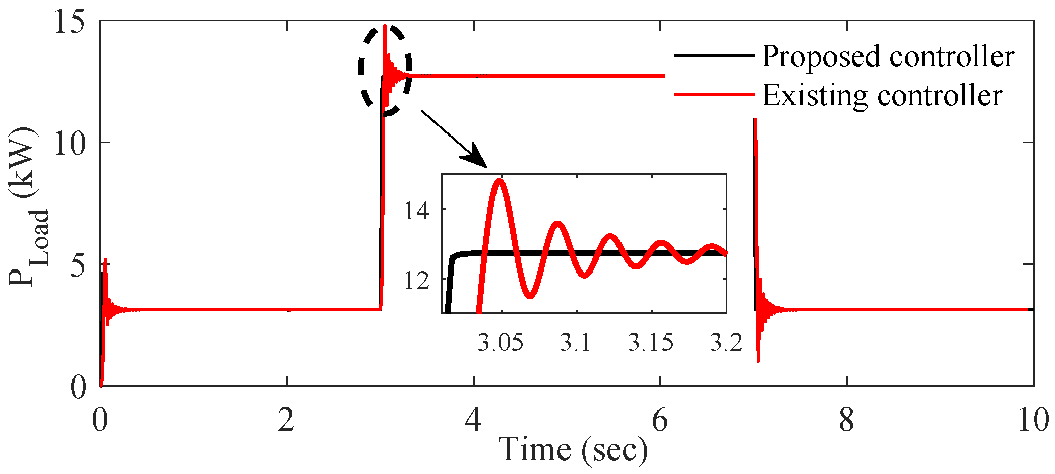
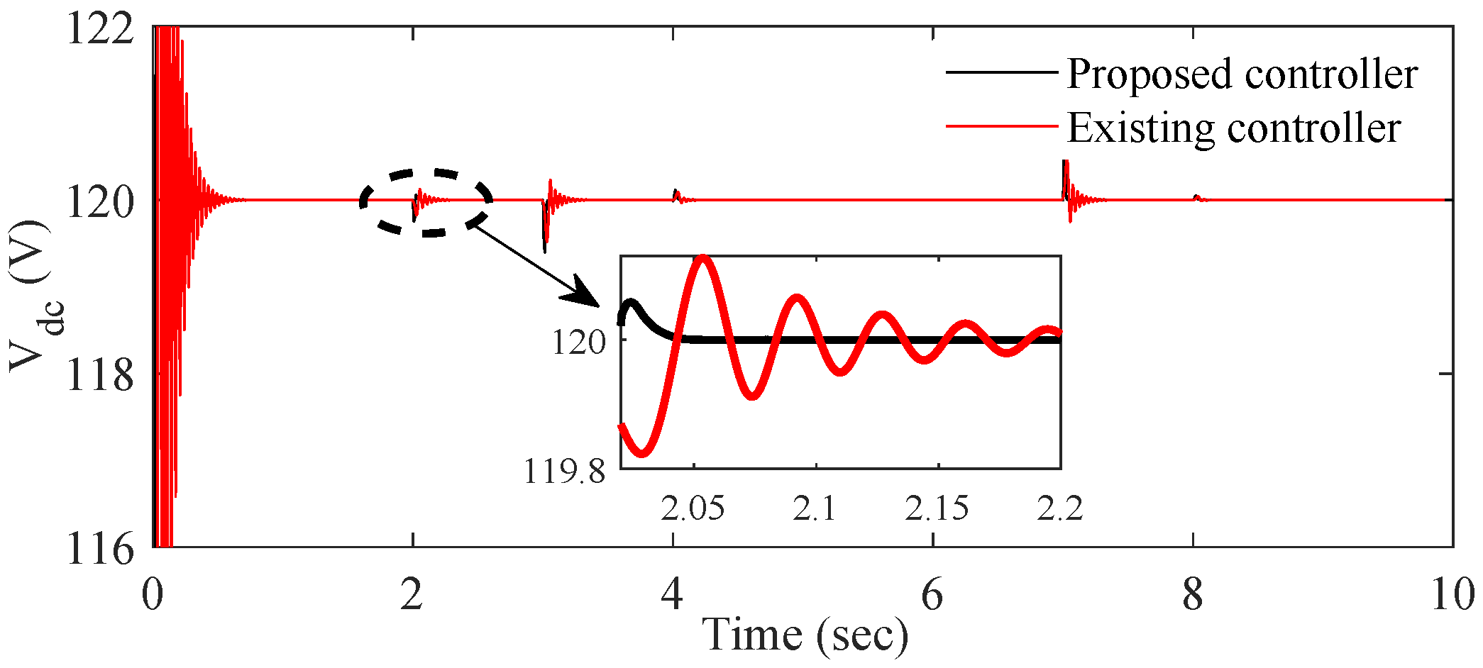
- The designed controller’s performance is far better compared to the existing controller in reducing transient and undesirable spikes and oscillations.
- In terms of quantitative (e.g., overshoot and settling time) analysis, the percentage of all responses is lowest when the proposed controller is used. It is obvious that the proposed controller shows a 58% improvement in settling time and a 82% improvement in overshoot compared to the existing controller.
In the future, an adaptive PID-HOSMC will be developed specifically tailored to address the challenges posed by uncertainties in system parameters. This advanced controller will be designed to dynamically adjust its control parameters and strategies in response to changing conditions, ensuring robust and effective performance in the face of variable and unpredictable factors. Moreover, a disturbance observer will be designed to observe external disturbances. This development will represent a significant step towards further improving the system’s resilience and adaptability in real-world applications.
Author Contributions
Conceptualization, T.K.R. and S.K.G.; methodology, T.K.R.; software, T.K.R. and S.K.G.; validation, T.K.R.; formal analysis, T.K.R.; investigation, T.K.R., S.K.G. and A.M.T.O.; resources, T.K.R.; writing—original draft preparation, T.K.R. and S.K.G.; writing—review and editing, T.K.R. and S.K.G.; supervision, T.K.R. and A.M.T.O.; project administration, A.M.T.O. All authors have read and agreed to the current version of the manuscript.
Funding
This research received no external funding.
Data Availability Statement
Data is contained within the article.
Conflicts of Interest
The authors declare no conflicts of interest.
Abbreviations
The following abbreviations are used in this manuscript:
| ANN | Artificial neural network |
| BESS | Battery energy storage system |
| BSC | Backstepping controller |
| CRRL | Constant rate reaching law |
| DPRL | Double power reaching law |
| DG | Distributed generator |
| DDBPFC | DC-DC converter bidirectional power flow converter |
| DDBC | DC-DC boost converter |
| ESS | Energy storage system |
| FBLC | Feedback linearization controller |
| LCF | Lyapunov control function |
| MPC | Model predictive controller |
| NSFT | Nonsingular fast terminal |
| PID-HOSMC | Proportional integral derivative higher-order sliding mode control |
| SPV | Solar photovoltaic |
| HOSMC | Higher-order sliding mode controller |
| SoC | State of charge |
References
- Ghosh, S.K.; Roy, T.K.; Pramanik, M.A.H.; Sarkar, A.K.; Mahmud, M.A. An energy management system-based control strategy for DC microgrids with dual energy storage systems. Energies 2020, 13, 2992. [Google Scholar] [CrossRef]
- Bayod-Rújula, Á.A.; Tejero-Gómez, J.A. Analysis of the hybridization of PV plants with a BESS for annual constant power operation. Energies 2022, 15, 9063. [Google Scholar] [CrossRef]
- Fan, L.; Miao, Z.; Shah, S.; Koralewicz, P.; Gevorgian, V. Solar PV and BESS plant-level voltage control and interactions: Experiments and analysis. IEEE Trans. Energy Convers. 2023, 38, 1040–1049. [Google Scholar] [CrossRef]
- Roy, T.K.; Pramanik, M.A.H.; Ghosh, S.K. Design of an integral terminal-based sliding mode controller for PV and BESS-based DC microgrids. Energy Nexus 2022, 7, 100130. [Google Scholar] [CrossRef]
- Roy, T.K.; Ghosh, S.K.; Saha, S. Stability enhancement of battery energy storage and renewable energy-based hybrid AC/DC microgrids using terminal sliding mode backstepping control approaches. ISA Trans. 2023, 142, 40–56. [Google Scholar] [CrossRef] [PubMed]
- Eghtedarpour, N.; Farjah, E. Distributed charge/discharge control of energy storages in a renewable-energy-based DC micro-grid. IET Renew. Power Gener. 2014, 8, 45–57. [Google Scholar] [CrossRef]
- Franzese, P.; Ribera, M.; Cervone, A.; Iannuzzi, D. Optimized control strategy for single-phase multilevel cascaded converter in a distributed PV-BESS system. Electr. Power Syst. Res. 2023, 214, 108818. [Google Scholar] [CrossRef]
- Ye, Q.; Mo, R.; Li, H. Low-frequency resonance suppression of a dual-active-bridge DC/DC converter enabled DC microgrid. IEEE J. Emerg. Sel. Top. Power Electron. 2017, 5, 982–994. [Google Scholar] [CrossRef]
- Lu, Z.; Wang, L.; Wang, P. Review of voltage control strategies for DC microgrids. Energies 2023, 16, 6158. [Google Scholar] [CrossRef]
- Sevostyanov, N.A.; Gorbunov, R.L. Control strategy to mitigate voltage ripples in droop-controlled DC microgrids. IEEE Trans. Power Electron. 2023, 38, 15377–15389. [Google Scholar] [CrossRef]
- Korompili, A.; Monti, A. Review of modern control technologies for voltage regulation in DC/DC converters of DC microgrids. Energies 2023, 16, 4563. [Google Scholar] [CrossRef]
- Massenio, P.R.; Tipaldi, M.; Rizzello, G.; Brescia, E.; Cascella, G.L.; Naso, D. Gain-scheduled structured control in DC microgrids. IEEE Trans. Control. Syst. Technol. 2023, 31, 2571–2583. [Google Scholar] [CrossRef]
- Vigneysh, T.; Kumarappan, N. Autonomous operation and control of photovoltaic/solid oxide fuel cell/battery energy storage based microgrid using fuzzy logic controller. Int. J. Hydrogen Energy 2016, 41, 1877–1891. [Google Scholar] [CrossRef]
- Roy, T.K.; Mahmud, M.A.; Oo, A.M.T.; Haque, M.E.; Muttaqi, K.M.; Mendis, N. Nonlinear adaptive backstepping controller design for islanded DC microgrids. IEEE Trans. Ind. Appl. 2018, 54, 2857–2873. [Google Scholar] [CrossRef]
- Basantes, J.A.; Paredes, D.E.; Llanos, J.R.; Ortiz, D.E.; Burgos, C.D. Energy management system (EMS) based on model predictive control (MPC) for an isolated DC microgrid. Energies 2023, 16, 2912. [Google Scholar] [CrossRef]
- Guo, Q.; Bahri, I.; Diallo, D.; Berthelot, E. Model predictive control and linear control of DC–DC boost converter in low voltage DC microgrid: An experimental comparative study. Control Eng. Pract. 2023, 131, 105387. [Google Scholar] [CrossRef]
- Mardani, M.M.; Khooban, M.H.; Masoudian, A.; Dragičević, T. Model predictive control of DC-DC converters to mitigate the effects of pulsed power loads in naval DC microgrids. IEEE Trans. Ind. Electron. 2018, 66, 5676–5685. [Google Scholar] [CrossRef]
- Dragičević, T. Dynamic stabilization of DC microgrids with predictive control of point-of-load converters. IEEE Trans. Power Electron. 2018, 33, 10872–10884. [Google Scholar] [CrossRef]
- Ansari, S.; Zhang, J.; Singh, R.E. A review of stabilization methods for DCMG with CPL, the role of bandwidth limits and droop control. Prot. Control Mod. Power Syst. 2022, 7, 2. [Google Scholar] [CrossRef]
- Mahmud, M.A.; Roy, T.K.; Saha, S.; Haque, M.E.; Pota, H.R. Robust nonlinear adaptive feedback linearizing decentralized controller design for islanded DC microgrids. IEEE Trans. Ind. Appl. 2019, 55, 5343–5352. [Google Scholar] [CrossRef]
- Roy, T.K.; Mahmud, M.A. Active power control of three-phase grid-connected solar PV systems using a robust nonlinear adaptive backstepping approach. Sol. Energy 2017, 153, 64–76. [Google Scholar] [CrossRef]
- Roy, T.K.; Mahmud, M.A. Dynamic stability analysis of hybrid islanded DC microgrids using a nonlinear backstepping approach. IEEE Syst. J. 2017, 12, 3120–3130. [Google Scholar] [CrossRef]
- Panda, S.K.; Subudhi, B. An extended state observer based adaptive backstepping controller for microgrid. IEEE Trans. Smart Grid 2024, 15, 171–178. [Google Scholar] [CrossRef]
- Mi, Y.; Zhang, H.; Fu, Y.; Wang, C.; Loh, P.C.; Wang, P. Intelligent power sharing of DC isolated microgrid based on fuzzy sliding mode droop control. IEEE Trans. Smart Grid 2018, 10, 2396–2406. [Google Scholar] [CrossRef]
- Zhang, G.; Tong, D.; Chen, Q.; Zhou, W. Sliding mode control against false data injection attacks in DC microgrid systems. IEEE Syst. J. 2023, 17, 6159–6168. [Google Scholar] [CrossRef]
- Wang, Y.; Duan, G.; Yu, J.; Yue, W.; Ning, J.; Liu, B. Harmonic analysis of sliding-mode-controlled buck converters imposed by onmodeled dynamics of hall sensor. Energies 2023, 16, 6124. [Google Scholar] [CrossRef]
- Ortiz-Castrillón, J.R.; Saldarriaga-Zuluaga, S.D.; Muñoz-Galeano, N.; López-Lezama, J.M.; Benavides-Córdoba, S.; Cano-Quintero, J.B. Optimal sliding-mode control of semi-bridgeless boost converters considering power factor corrections. Energies 2023, 16, 6282. [Google Scholar] [CrossRef]
- Liang, C.; Zhang, Y.; Ji, X.; Meng, X.; An, Y.; Yao, Q. DC bus voltage sliding-mode control for a DC microgrid based on linearized feedback. In Proceedings of the Chinese Automation Congress, Hangzhou, China, 22–24 November 2019; pp. 5380–5384. [Google Scholar]
- Esmaeli, A. RETRACTED: Stability analysis and control of microgrids by sliding mode control. Int. J. Electr. Power Energy Syst. 2016, 78, 22–28. [Google Scholar] [CrossRef]
- Kalla, U.K.; Singh, B.; Murthy, S.S.; Jain, C.; Kant, K. Adaptive sliding mode control of standalone single-phase microgrid using hydro, wind, and solar PV array-based generation. IEEE Trans. Smart Grid 2017, 9, 6806–6814. [Google Scholar] [CrossRef]
- Chaturvedi, S.; Fulwani, D.; Guerrero, J.M. Adaptive-SMC based output impedance shaping in DC microgrids affected by inverter loads. IEEE Trans. Sustain. Energy 2020, 11, 2940–2949. [Google Scholar] [CrossRef]
- Gudey, S.K.; Gupta, R. Recursive fast terminal sliding mode control in voltage source inverter for a low-voltage microgrid system. IET Gener. Transm. Distrib. 2016, 10, 1536–1543. [Google Scholar] [CrossRef]
- Kumar, V.; Mohanty, S.R.; Kumar, S. Event trigger super twisting sliding mode control for DC micro grid with matched/unmatched disturbance observer. IEEE Trans. Smart Grid 2020, 11, 3837–3849. [Google Scholar] [CrossRef]
- Amine, H.M.; Mouaz, A.K.; Messaoud, H.; Othmane, A.; Saad, M. The impacts of control systems on hybrid energy storage systems in remote DC-microgrid system: A comparative study between PI and super twisting sliding mode controllers. J. Energy Storage 2022, 47, 103586. [Google Scholar] [CrossRef]
- Khan, T.A.; Ullah, A.; Hafeez, G.; Khan, I.; Murawwat, S.; Ali, F.; Ali, S.; Khan, S.; Rehman, K. A fractional order super twisting sliding mode controller for energy management in smart microgrid using dynamic pricing approach. Energies 2022, 15, 9074. [Google Scholar] [CrossRef]
- Zeb, K.; Busarello, T.D.C.; Ul Islam, S.; Uddin, W.; Raghavendra, K.V.G.; Khan, M.A.; Kim, H.J. Design of super twisting sliding mode controller for a three-phase grid-connected photovoltaic system under normal and abnormal conditions. Energies 2020, 13, 3773. [Google Scholar] [CrossRef]
- Yeasmin, S.; Roy, T.K.; Ghosh, S.K. Design of robust integral terminal sliding mode controllers with exponential reaching laws for solar PV and BESS-based DC microgrids with uncertainties. Sustainability 2022, 14, 7802. [Google Scholar] [CrossRef]
- Xiang, C.; Cheng, Q.; Zhu, Y.; Zhao, H. Sliding mode control of ship DC microgrid based on an improved reaching law. Energies 2023, 16, 1051. [Google Scholar] [CrossRef]
- Armghan, H.; Yang, M.; Ali, N.; Armghan, A.; Alanazi, A. Quick reaching law based global terminal sliding mode control for wind/hydrogen/battery DC microgrid. Appl. Energy 2022, 316, 119050. [Google Scholar] [CrossRef]
- Abdalla, Y.S.; Ali, N.; Alanazi, A.; Alanazi, M.; Armghan, H.; Sharaf, M.A.; Boudabbous, A.R.; Armghan, A. Fast reaching law based integral terminal sliding mode controller for photovoltaic-fuel cell-battery-super capacitor based direct-current microgrid. J. Energy Storage 2022, 56, 105915. [Google Scholar] [CrossRef]
Disclaimer/Publisher’s Note: The statements, opinions and data contained in all publications are solely those of the individual author(s) and contributor(s) and not of MDPI and/or the editor(s). MDPI and/or the editor(s) disclaim responsibility for any injury to people or property resulting from any ideas, methods, instructions or products referred to in the content. |
© 2024 by the authors. Licensee MDPI, Basel, Switzerland. This article is an open access article distributed under the terms and conditions of the Creative Commons Attribution (CC BY) license (https://creativecommons.org/licenses/by/4.0/).