Abstract
The well-established practice of integrating heat pipes into thermosyphons is recognized for its efficacy in achieving energy savings. This integration facilitates heat transfer and fluid circulation without requiring additional pumps or energy input, resulting in reduced consumption, lowered operational costs, and an overall improvement in system efficiency. This research explores the energy-saving potential of closed-loop thermosyphons, with a specific focus on their integration in latent heat-based heat pipe technologies in industrial settings. The study systematically investigates the influence of thermosyphon orientation on energy efficiency through a combination of experiments and computational fluid dynamics (CFD) simulations. Thereby, it results in superior heat transfer rates in forced convection scenarios. A closed-loop thermosyphon heat exchanger undergoes evaluation in three panel installation configurations relative to the ground, taking into consideration factors including copper diameters, coolants (with or without R410a), and temperature conditions. CFD validation identifies an efficient thermosyphon design—a panel oriented perpendicularly to the ground and filled with R410a refrigerant at 90 °C. It utilizes a 19.05 mm copper tube for forced convection. This optimized design demonstrates a commendable heat transfer rate of 1485 W and a heat transfer coefficient of 1252 W/(m2·K), significantly enhancing thermal process efficiency and resulting in notable energy savings.
1. Introduction
Heat pipes are increasingly playing a significant role in various industrial applications, especially in the enhancement of thermal performance in heat exchangers and the augmentation of energy savings, both of which can be achieved without external energy input [1,2]. Thermosyphons are being employed by many researchers in rooftop solar collectors [3,4,5,6], both on the rooftop itself [7] and in photovoltaic systems, to conserve energy and reduce electrical costs [8]. Heat pipes have found extensive utility in diverse engineering applications, including heating, ventilation, and air-conditioning systems [9], ground source heat pumps [10], water heating systems [11], and electronics thermal management [12]. Their prevalence in these domains can be attributed to their straightforward structure, exceptional flexibility, high efficiency, compact design, and remarkable reversibility [13,14,15,16]. A heat pipe, known as a thermosyphon, consists of a sealed container lined with wicking material. This container is vacuum-sealed and filled with a specific volume of liquid, as depicted in Figure 1 (adapted from Figure 1 of [17]). A thermosyphon heat pipe comprises three principal components: the evaporating section, the adiabatic section, and the condensing section. These heat pipes are charged with a working fluid, such as water [18,19,20]. Thermosyphon systems operate through natural convection to circulate a fluid, typically a refrigerant, without the need for a pump. The selection of the working fluid is of great importance, as each heat pipe application requires specific temperature operating ranges. Consequently, when designing a heat pipe, careful consideration must be given to the intended temperature range through the selection of an appropriate working fluid. For low-temperature applications, working fluids such as ammonia, as well as various refrigerants like R134a [20,21,22,23], R22, and R410a [24], have been employed. These working fluids are used in conjunction with compatible metals such as copper, steel, and aluminum as shell materials [13,25]. The primary focus of this paper centers on R410a as the coolant for cases involving filled refrigerant. This selection is motivated by the environmentally friendly nature of R410a, making it a potential candidate for replacing R134a, which currently serves as the industrial standard. To obtain a comprehensive understanding of the distinctive attributes of R410a, refer to Table 1 [23].
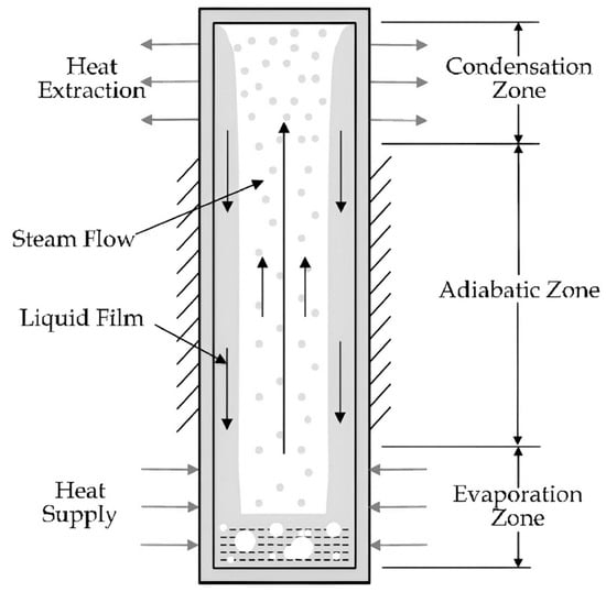
Figure 1.
Cross-sectional view of thermosyphon.

Table 1.
Characteristic properties of R410a [23].
Numerous factors influence the performance of a thermosyphon. Figure 2 provides a visual representation of the experimental studies conducted by various researchers. Experimental investigations regarding refrigerants in thermosyphons dominate, as they find application in multiple fields, including external influences, coated surfaces, and modified designs. The emission of refrigerants with high ozone depletion potential (ODP) and global warming potential (GWP) has substantial environmental consequences [26,27]. To attain an optimized closed-loop thermosyphon design, careful consideration must be given to the choice of fill liquid, the inclination angle relative to the horizontal (θ), and the length-to-diameter aspect ratio (AR). Ong et al. [28] have observed that both the fill ratio (FR) and inclination angle exert insignificant impacts on thermosyphon performance. The fill ratio (FR) denotes the liquid volume in relation to the evaporator’s volume, and it holds particular significance, as excessive liquid can lead to flooding, while insufficient liquid results in dryness. Both flooding and dryness are undesirable as they detrimentally affect thermosyphon performance. The inclination of the thermosyphon also influences its thermal performance by affecting the flow of condensate back to the evaporator section. Furthermore, proper system design and sizing are essential to ensure optimal operation, irrespective of the inclination angle. Engineering and thermodynamic considerations are pivotal in achieving energy savings within thermosyphon systems. Implementing a thermosyphon system within an industrial facility represents an effective approach to augmenting heat transfer and conserving energy, particularly in processes involving heat exchange and temperature regulation. The selection of the appropriate thermosyphon system necessitates careful consideration of several key factors that are pivotal for ensuring energy efficiency (see more details in Section 4 below).
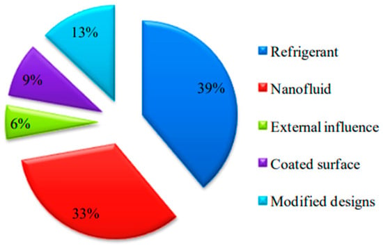
Figure 2.
Classification of experimental investigations based on various parameters.
In this research, the optimization of a closed-loop thermosyphon heat exchanger is investigated through a combination of experimental studies and simulations conducted with Ansys and Fluent software 2022. The oriented angle at which a thermosyphon system is installed significantly influences its energy-saving efficiency. To assess this, various adjustments are analyzed in closed-loop copper thermosyphons across three scenarios: (I) parallel with the ground, (II) perpendicular to the ground, and (III) changing the axis of the thermosyphon to be perpendicular to the ground. Additionally, a comparative analysis is performed on closed-loop thermosyphons under both free and forced convection conditions, taking into account variations in copper diameters (12.700, 15.875, and 19.050 mm), in coolants (presence or absence of R410a), and in temperatures (50, 60, 70, 80, and 90 °C). This exhaustive work aims to obtain the optimal setup solution, relying on three panel installation configurations, two types of coolants, five varying temperatures, and three sizes of copper tubes and encompassing both free and forced convection scenarios.
2. Theories
The copper thermosyphon tube is hermetically sealed at both ends and contains a specific quantity of working fluid, which varies according to the nature of the experiment. In this instance, the working fluid selected is R410a, which is prized for its low boiling point, facilitating efficient heat transfer. The heat transfer rate of the thermosyphon can be calculated by considering the heat transfer at the evaporation section, while taking into account the working fluid quantity and its specific heat (as detailed in Equation (1) of [17,29,30,31]):
where is the specific heat associated with the working fluid, is the water temperature difference between the inlet and the outlet and is the mass flow rate of the water (Equation (2) of [32]):
where is the water density, is the water velocity, and is the cross-sectional area of water flow.
Thermal resistances and an equivalent circuit are shown in Figure 3, as detailed in Figure 2.8 of [7]). Specifically, Z1 and Z9 represent the heat transfer resistances associated with heating a solid surface. Z2 and Z8 denote the thermal resistances pertaining to the heat pipe wall. Z3 and Z7 characterize the thermal resistances of the wick structure, while Z4 and Z6 signify the thermal resistance corresponding to the vapor–liquid surfaces. Z5 represents the thermal resistance of the saturated vapor, and Z10 corresponds to the axial conduction thermal resistance through the heat pipe wall. The heat transfer mechanism in the heat pipe involves the ingress of heat from a heat source and its egress through a heat sink, mediated by conduction, convection, or thermal radiation. Additionally, electron bombardment or eddy currents may be utilized to heat the heat pipe, and electron emission can serve for cooling, as outlined in [7]. This thermal process induces a temperature difference through the evaporator and condenser walls, with thermal resistance manifesting at both vapor and liquid surfaces. The evaluation of heat pipe performance hinges on a thorough consideration of the overall thermal resistance, which has been extensively discussed in [33,34,35]. Mathematical expressions defining the thermal resistance network can be found in Tables 2 and 3 of [7] as well as in the pertinent literature [36]. It is important to highlight that this analysis excludes the consideration of heat transfer between vapor and liquid phases (Z4, Z6), the pressure drop across the vapor–liquid interface (Z5), the longitudinal pipe resistance (Z10), and external surface heat resistance (Z1, Z9). The total thermal resistance is, therefore, determined as follows:
which can be expressed as the overall heat transfer coefficient:
where the heat transfer coefficients, inside of the condenser and evaporation, are as follows (Equations (10) and (11) of [37]):
and the inside of evaporation area is
where and are the inner radii and the length of copper tube. The percentage between sections filled and unfilled with R410a can be calculated by
which we will use below.
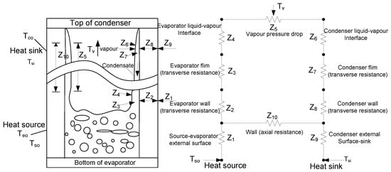
Figure 3.
Thermal-resistant circuit of thermosyphon heat pipe.
3. Methodology
In this paper, a thermosyphon is investigated through experiments and computational fluid dynamics under conditions involving both filled and unfilled R410a, considering free and forced convections. Further details are provided below.
3.1. Experimental Setup
In this section, experiments were conducted to validate the performance of the actual working fluid. The experiments encompassed temperature conditions at various locations on the thermosyphon panel, comparing the performance of three thermosyphon tube sizes, 12.700 mm, 15.875 mm, and 19.05 mm, both with and without the use of R410a refrigerant. The materials and equipment used in the experiment included (1) a heat transfer testing apparatus for free convection, employing a closed-loop thermosyphon and thermosyphon panel setups with copper tubes (as depicted in Figure 3), (2) heat dissipation fan equipment, (3) a data logger device, model MW 100, (4) a timer, (5) a precision scale, (6) air-conditioning equipment, (7) R410a refrigerant, and (8) a manifold gauge. To examine variations in closed-loop copper thermosyphon adjustments, three cases were considered: (I) perpendicular to the ground, (II) parallel to the ground, and (III) the axis changed to be perpendicular to the ground (see Figure 4). Additionally, thermosyphon performance was tested under different coolant temperatures (ranging from 50 °C to 90 °C) with a water flow rate of 2 GPM and a wind flow rate of 10.5 m/s. The inner and outer capillary tubes were tested with diameters of 2.16 mm and 3.16 mm.
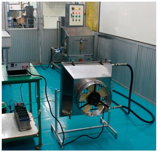
Figure 4.
Experimental setup for closed-loop thermosyphon.
The experimental operating conditions are shown in Table 2. The experimental procedure is divided into two main parts: an experiment conducted with and without R410a.
The steps of experimental preparation are as follows:
- Filling the water boiling tank with clean water, ensuring that the upper heater portion is submerged and the water level is appropriate for use;
- Setting up electrical equipment requiring a 220 V, 50 Hz power supply;
- Preparing a timer for experiment timing;
- Weighing the refrigerants used in the experiment using a precision scale;
- Connecting the data logger (Model MW 100) to the computer for data recording;
- Adjusting the room temperature to approximately 28 °C, as specified;
- Installing the closed thermosyphon panel setup for all three tube sizes, the fan system for heat dissipation with the thermosyphon panel setups, and the power converter to supply 12 V 28 A power to the heat dissipation fans.

Table 2.
Summary of experimental runs.
Table 2.
Summary of experimental runs.
| Run * | Case | Heat Transfer | R410a | Coolant Temperature (°C) | Size of Copper Tube (mm) |
|---|---|---|---|---|---|
| 1 | I | Free convection | Filled | 50, 60, 70, 80, 90 | 12.700, 15.875, 19.050 |
| 2 | II | 50, 60, 70, 80, 90 | 12.700, 15.875, 19.050 | ||
| 3 | III | 50, 60, 70, 80, 90 | 12.700, 15.875, 19.050 | ||
| 4 | I | Unfilled | 50, 60, 70, 80, 90 | 12.700, 15.875, 19.050 | |
| 5 | II | 50, 60, 70, 80, 90 | 12.700, 15.875, 19.050 | ||
| 6 | III | 50, 60, 70, 80, 90 | 12.700, 15.875, 19.050 | ||
| 7 | I | Forced convection | Filled | 50, 60, 70, 80, 90 | 12.700, 15.875, 19.050 |
| 8 | II | 50, 60, 70, 80, 90 | 12.700, 15.875, 19.050 | ||
| 9 | III | 50, 60, 70, 80, 90 | 12.700, 15.875, 19.050 | ||
| 10 | I | Unfilled | 50, 60, 70, 80, 90 | 12.700, 15.875, 19.050 | |
| 11 | II | 50, 60, 70, 80, 90 | 12.700, 15.875, 19.050 | ||
| 12 | III | 50, 60, 70, 80, 90 | 12.700, 15.875, 19.050 |
* Repeat 3 times per run.
3.2. Computational Fluid Dynamics (CFD)
In the field of fluid dynamics, encompassing heat and mass transfer, chemical reactions, and related phenomena, computational fluid dynamics (CFD) stands as a numerical technique used for solving the governing mathematical equations. It enables the prediction of approximate solutions. Addressing challenges related to heat and mass transfer and fluid flow involves three main, traditionally employed approaches: analytical, experimental, and computational methods [38,39,40,41,42]. For this study, Ansys Fluent was employed for modeling and analysis, thanks to a research-licensed version generously provided by King Mongkut’s University of Technology North Bangkok (KMUTNB).
In the research, a thermosyphon was examined, consisting of copper tubing, with three distinct sizes characterized by inner diameters of 12.70 mm, 15.875 mm, and 19.05 mm, each maintaining a consistent thickness of 2 mm. The total length of the thermosyphon extends to 2550 mm, and its schematic representation is displayed in Figure 5. Computational fluid dynamics (CFD) modeling was employed, utilizing deionized water (H2O) and the R-410a cooling agent as analyzed fluids. Comprehensive properties of the R-410a cooling agent can be found in Table 1. The influence of fluid temperature on the heat transfer rate was investigated by systematically varying the fluid inlet temperature, ranging from 50 °C to 90 °C. Analyses were performed under both free and forced convection conditions at the wall surface to determine the heat transfer rate, with the results subsequently being compared to experimental data. Further details regarding the boundary conditions imposed within the computational domain are available in Table 3.
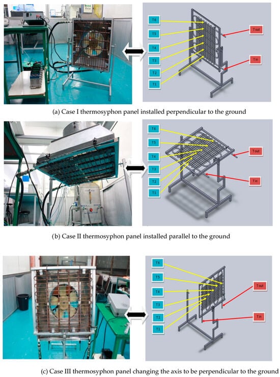
Figure 5.
The experimental apparatus of the closed-loop thermosyphon panel installation: (a) perpendicular, (b) parallel, and (c) changing axis to be perpendicular to the ground.
To further the study of heat pipes, it is necessary to introduce a CFD two-phase flow model to describe the heat and mass transfer mechanisms and involved evaporation and condensation processes.

Table 3.
Boundary conditions imposed on the computational domain.
Table 3.
Boundary conditions imposed on the computational domain.
| Boundary Surface | Boundary Condition |
|---|---|
| Inlet | The mass flow rate of study fluid is kept constant at 0.126 with varying inlet temperature. |
| Outlet | Outflow condition. |
| Wall surface | Free convection: the ambient air temperature is held constant at 28 °C.Forced convection: the airflow rate is forced at 10.5 m/s into the analysis model, which is situated at a distance of 1.5 m. |
Numerical simulations were performed by utilizing a CFD solver based on double precision. The analysis encompassed two equations: one related to energy and another for the standard k-epsilon model. The criteria for model convergence were met when the residuals within the computational domain registered values below 10−6. The exploration of grid independence was centered on the assessment of four distinct mesh densities, as illustrated in Figure 6: 88, 768; 231, 804; 352, 601; and 863, 300 hexahedral elements. It was noted that the solution exhibited consistent behavior, irrespective of variations in mesh resolution. Furthermore, the standard deviation was only 0.19, confirming that additional mesh refinement would have a negligible impact on the solution. Therefore, the decision was made to employ 88,768 grids in this model to enhance computational efficiency. Figure 7 provides details regarding the grid size and type.
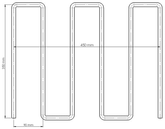
Figure 6.
Schematic of thermosyphon used to study in this research.
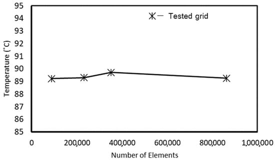
Figure 7.
Influence of grid density on the outlet temperature.
Temperature and Heat Transfer Rate Analysis
The heat and mass transfer mechanisms involved in evaporation and condensation processes in the thermosyphon are the subject of this study. Surface temperature distributions for a copper tube with a 12.7 mm diameter under free convection and a 19.05 mm diameter under forced convection conditions, with a fluid inlet temperature of 90 °C, reveal interesting insights, as shown in Figure 8 In both cases, thermal gradients confirm that forced convection results in a higher heat transfer rate () compared to free convection. It is worth noting that the temperature change (∆T) between regions T1 and T6 differs significantly, amounting to 0.64 °C for the 12.7 mm diameter copper tube under free convection and 2.42 °C for the 19.05 mm diameter copper tube under forced convection.
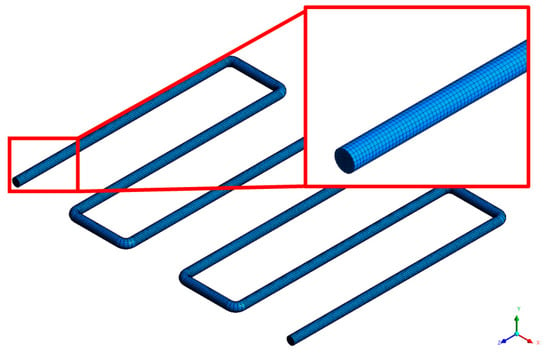
Figure 8.
Grid size and type used in this research.
Moving to the comparative analysis of the heat transfer rates () derived from both experimental and computational fluid dynamics (CFD) analyses, the results are presented in Figure 9. Notably, there is a close agreement between the experimental and CFD results, but deviations are apparent. These differences amount to roughly 10% for free convection conditions and 18% for forced convection conditions. The variations occurring in turbulent airflow patterns along the tube surfaces in both the experimental and CFD simulations can introduce temperature distribution fluctuations, leading to observable oscillations in the results.
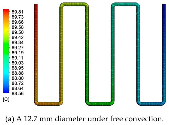
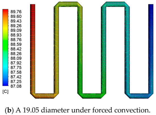
Figure 9.
Distribution of copper tube surface temperatures: (a) copper tube with a diameter of 12.7 mm under free convection conditions and (b) copper tube with a diameter of 19.05 mm under forced convection.
4. Results and Discussion
The experiment involved three thermosyphon configurations: parallel, perpendicular, and angled types, each employing copper tubes with diameters ranging from 12.700 mm to 19.050 mm. These configurations were tested under five different coolant temperatures, ranging from 50 °C to 90 °C, with variations that included both filled and unfilled R410a and assessments of free and forced convection (see Table 2).
From Table 4, Table 5 and Table 6, we see that heat transfer rates () reveal a linear increase in with both copper diameter and coolant temperature. Insights drawn from Table 4 highlight that the maximum heat transfer rate () is attained when using the thermosyphon panel setup with a 19.05 mm diameter, utilizing forced convection heat transfer with R410a at 90 °C. This achievement can be attributed to the extensive heat transfer surface area provided by the 19.05 mm tube and the elevated 90 °C temperature, which is the highest achieved within this study. When comparing the three thermosyphon installation cases for heat transfer rates, the hierarchy is as follows: Case I > Case III > Case II. This trend is corroborated by Figure 10, which further demonstrates that the heat transfer rate is at its peak with the 19.05 mm configuration under forced convection conditions and lowest with the 12.70 mm configuration under free convection conditions. These findings align with previous research by Ong and Lim [18,22], who identify the thermosyphon panel installed perpendicular to the ground (Case I) as the most efficient configuration. They also note that higher power input results in elevated thermosyphon wall temperatures. Similar experiments conducted by Ziyan et al. [20] involved a comparative analysis of heat transfer rates in thermosyphons working with water and R134a refrigerant.

Table 4.
Rate of heat transfer () for thermosyphon panel (Case I).

Table 5.
Rate of heat transfer () for thermosyphon panel (Case II).

Table 6.
Rate of heat transfer () for thermosyphon panel (Case III).
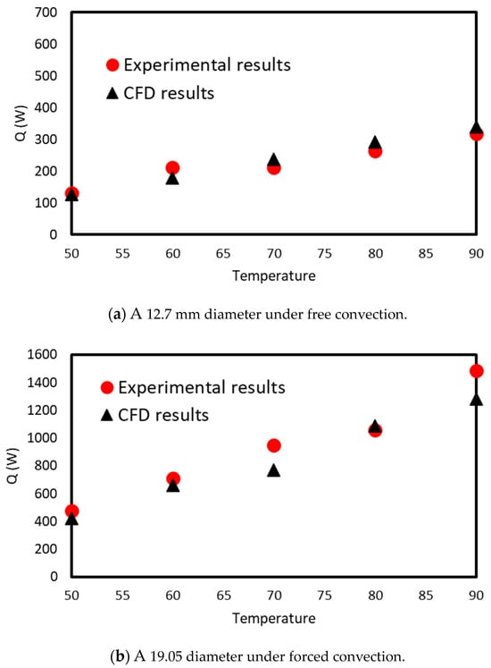
Figure 10.
The comparison of the heat transfer rate () coupled with both experimental and CFD analyses of the conditions: (a) a copper tube with a 12.7 mm diameter of under free convection and (b) a copper tube with a 19.05 mm diameter under forced convection.
Table 7, Table 8 and Table 9 further confirm that, in closed thermosyphon tubes using R410a for forced convection heat transfer, the heat transfer coefficient, , is superior to that of the unfilled configuration, as expected. Notably, the 19.05 mm tube size exhibited the highest heat transfer coefficient. Additionally, the ranking of heat transfer coefficients is as follows: Case I > Case II > Case III.

Table 7.
Heat transfer coefficients () for thermosyphon panel Case I.

Table 8.
Heat transfer coefficients () for thermosyphon panel Case II.

Table 9.
Heat transfer coefficients () for thermosyphon panel Case III.
Based on the data in Table 10, the greatest percentage disparity in heat transfer rates between thermosyphon tubes filled and unfilled with R410a at a temperature of 90 °C is observed in the case of a 19.05 mm tube setup installed with an axis perpendicular to the ground, yielding a maximum difference of 13.66%. Similarly, as shown in Table 11, the most significant percentage variation in heat transfer rates occurs between forced and free convection heat dissipation for a 19.05 mm tube setup installed parallel to the ground (Case II), with a notable maximum difference of 75.2%.

Table 10.
The percentage comparison of heat transfer rates between R410a-filled and unfilled systems at a coolant temperature of 90 °C in three thermosyphon installation cases with free convection.

Table 11.
The percentage comparison of heat transfer rates between filled and unfilled R410a at a coolant temperature of 90 °C for three thermosyphon installation cases with forced convection.
Technical and engineering challenges in this research include:
- (1)
- Precision in joining and bending copper pipes to prevent potential damage.
- (2)
- Challenges related to the installation and calibration of data measurement points within thermosyphon tubes.
- (3)
- Limitations in temperature control due to the accuracy of data acquisition equipment.
The selection of the appropriate thermosyphon system necessitates careful consideration of several key factors that are pivotal for ensuring energy efficiency.
(1) Working fluid selection: The choice of working fluid is paramount to achieving efficient heat transfer. The selected fluid must possess desirable thermophysical properties, notably a high latent heat of vaporization, while also being compatible with the system’s materials.
(2) System design and sizing: Precise design and sizing are imperative to guarantee the system’s efficient operation. Critical factors to contemplate include pipe diameter, length, and orientation, all of which exert influence on flow rates and heat transfer capacity.
(3) Heat source and heat sink integration: For optimal energy conservation, effective integration of the thermosyphon system with the heat source (e.g., industrial equipment) and the heat sink (e.g., cooling systems) is essential to maximize heat recovery.
(4) Insulation: Adequate insulation of thermosyphon pipes assumes significance in mitigating heat losses, particularly in applications where the maintenance of elevated temperatures holds great importance.
(5) Monitoring and control: Implementation of sensors and control mechanisms is necessary to monitor and manage the thermosyphon system, allowing for adjustments and optimizations to maintain peak operational efficiency.
(6) Safety measures: The inclusion of safety features is vital to avert system malfunctions, overheating, and overpressure conditions.
(7) Regular maintenance: Prescheduled maintenance activities are imperative to sustain the system’s operational integrity. This encompasses tasks such as leak detection, cleaning, and component replacement as dictated by requirements.
(8) System efficiency analysis: Routine analysis of energy savings realized by the thermosyphon system is essential. This analytical approach facilitates adjustments based on empirical data and operational feedback, thereby maximizing efficiency.
To optimize heat transfer efficiency, it is recommended to transition from a single-phase closed-loop system to a two-phase closed-loop thermosyphon [43]. Additionally, the introduction of a nanoparticle fluid, such as graphene–acetone [32], also has the potential to significantly enhance thermal efficiency and elevate the convective heat transfer coefficient when compared to traditional working fluids.
Based on an exhaustive review of prior research [27], we strongly endorse the integration of a solar photovoltaic system to power a two-phase closed thermosyphon. Despite the relatively prolonged payback period associated with this approach, it effectively reduces indirect emissions tied to fossil-fuel-based grid electricity generation. The utilization of two-phase closed thermosyphons over single-phase systems within this study presents a commendable challenge for potential researchers. This choice not only introduces a formidable endeavor but also unveils a multitude of opportunities for the development of environmentally sustainable, economically valuable, refrigerant-based, solar-operated two-phase closed-loop thermosyphons.
5. Conclusions
This research systematically explores the efficacy of closed-loop thermosyphons, a latent heat-based heat pipe technology, for energy conservation in industrial settings. Employing a comprehensive methodology that combines experimental investigations and computational fluid dynamics simulations, the study scrutinizes the impact of thermosyphon orientation on energy efficiency. Forced convection thermosyphons, particularly those oriented perpendicularly to the ground (Case I) with a 19.05 mm copper tube filled with R410a refrigerant at 90 °C, prove to be highly efficient in enhancing heat transfer, emphasizing their superiority through specific parameters. As validated by computational fluid dynamics, the optimal configuration is identified as a 19.05 mm tube filled with R410a at 90 °C. This designed thermosyphon exhibits a remarkable heat transfer rate of 1485 W and a heat transfer coefficient of 1252 W/(m2·K). Additionally, this paper underscores the significance of future research exploring various tilt angles for heat pipe performance, laying a crucial foundation for potential industrial implementation and advancing sustainable energy.
Author Contributions
N.R.: Conceptualization, Methodology, Investigation Writing—Original Draft Preparation. S.T.: Data Curation, Investigation. A.S.: Data Curation, Validation. B.D.: Validation, Reviewing and Editing. W.R. (corresponding author): Conceptualization, Supervision, Reviewing and Editing, Funding Acquisition, Project Administration. All authors have read and agreed to the published version of the manuscript.
Funding
This research has received funding support from the NSRF via the Program Management Unit for Human Resources & Institutional Development, Research and Innovation (grant number B01F650006).
Data Availability Statement
Our dataset was collected under laboratory conditions and is not au-thorized for publication.
Acknowledgments
The authors are grateful for the software license of Ansys Fluent, supported by King Mongkut’s University of Technology North Bangkok, and for the benefits derived from the substantial equipment resources provided by Rajamangala University of Technology Phra Nakhon.
Conflicts of Interest
The authors declare that they have no known competing financial interests or personal relationships that could have appeared to influence the work reported in this paper.
Nomenclature
| Roman symbols | |
| Area of evaporation, outside [m2] | |
| A | Cross-sectional area of water flow |
| Diameter, inner and outer [m] | |
| FR | Fill ratio |
| Heat capacity [kJ/kg·K) | |
| Heat conductivity [(W/m·K)] | |
| Heat transfer coefficient [W/m2.K] | |
| Heat transfer rate [kW] | |
| Le,Lc | Length, evaporator and condenser [m] |
| AR | Length/diameter aspect ratio |
| Mass flow rate [(kg/s)] | |
| Percentage difference of filled and unfilledcoolant of heat transfer rate [-] | |
| Radius [m] | |
| Z | Resistant in thermal circuit of thermosyphon |
| Te, Tc, Tsat | Temperature, evaporator, condenser and saturation [°C] |
| Greek symbols | |
| Density of the coolant at outside pipe (kg/m3) | |
| θ | Inclination to the horizontal |
| Temperature differences (K) | |
| Velocity of the coolant at outside pipe (m/s) | |
References
- Mantelli, M.B. Thermosyphon technology for industrial applications. In Heat Pipes and Solid Sorption Transformations: Fundamentals and Practical Applications; CRC Press: Boca Raton, FL, USA, 2013; pp. 411–464. [Google Scholar]
- Nadjahi, C.; Louahlia-Gualous, H.; Le Masson, S. Experimental study and analytical modeling of thermosyphon loop for cooling data center racks. Heat Mass Transf. 2019, 56, 121–142. [Google Scholar] [CrossRef]
- Ozsoy, A.; Corumlu, V. Thermal performance of a thermosyphon heat pipe evacuated tube solar collector using silver-water nanofluid for commercial applications. Renew. Energy 2018, 122, 26–34. [Google Scholar] [CrossRef]
- Azzolin, M.; Mariani, A.; Moro, L.; Tolotto, A.; Toninelli, P.; Del Col, D. Mathematical model of a thermosyphon integrated storage solar collector. Renew. Energy 2018, 128, 400–415. [Google Scholar] [CrossRef]
- Abreu, S.L.; Colle, S. An experimental study of two-phase closed thermosyphons for compact solar domestic hot-water systems. Sol. Energy 2004, 76, 141–145. [Google Scholar] [CrossRef]
- Jamil, M.M.; Sidik, N.A.C.; Yusof, S.N.A. Solar Collector Application using Nanofluid in Thermosyphon. J. Adv. Res. Mater. Sci. 2020, 65, 1–15. [Google Scholar] [CrossRef]
- Fadhl, B. Modelling of the Thermal Behaviour of a Two-Phase Closed Thermosyphon. Doctoral Dissertation, Brunel University London, London, UK, 2016. [Google Scholar]
- Akbarzadeh, A.; Wadowski, T. Heat pipe-based cooling systems for photovoltaic cells under concentrated solar radiation. Appl. Therm. Eng. 1996, 16, 81–87. [Google Scholar] [CrossRef]
- Kerrigan, K.; Jouhara, H.; O’donnell, G.; Robinson, A. Heat pipe-based radiator for low grade geothermal energy conversion in domestic space heating. Simul. Model. Pr. Theory 2011, 19, 1154–1163. [Google Scholar] [CrossRef]
- Jouhara, H.; Meskimmon, R. Experimental investigation of wraparound loop heat pipe heat exchanger used in energy efficient air handling units. Energy 2010, 35, 4592–4599. [Google Scholar] [CrossRef]
- Mathioulakis, E.; Belessiotis, V. A new heat-pipe type solar domestic hot water system. Sol. Energy 2002, 72, 13–20. [Google Scholar] [CrossRef]
- Weng, Y.-C.; Cho, H.-P.; Chang, C.-C.; Chen, S.-L. Heat pipe with PCM for electronic cooling. Appl. Energy 2011, 88, 1825–1833. [Google Scholar] [CrossRef]
- Jouhara, H. Economic assessment of the benefits of wraparound heat pipes in ventilation processes for hot and humid climates. Int. J. Low-Carbon Technol. 2009, 4, 52–60. [Google Scholar] [CrossRef]
- Parand, R.; Rashidian, B.; Ataei, A.; Shakiby, K. Modeling the Transient Response of the Thermosyphon Heat Pipes. J. Appl. Sci. 2009, 9, 1531–1537. [Google Scholar] [CrossRef]
- Ochsner, K. Carbon dioxide heat pipe in conjunction with a ground source heat pump (GSHP). Appl. Therm. Eng. 2008, 28, 2077–2082. [Google Scholar] [CrossRef]
- Du, J.; Bansal, P.; Huang, B. Simulation model of a greenhouse with a heat-pipe heating system. Appl. Energy 2012, 93, 268–276. [Google Scholar] [CrossRef]
- Wongtom, S.; Kiatsiriroat, T. Effect of inclined heat transfer rate on thermosyphon heat pipe under sound wave. Asian J. Energy Environ. 2009, 10, 214–220. [Google Scholar]
- Ong, K.S.; Lim, C. Performance of water filled thermosyphons between 30–150 degC. Front. Heat Pipe 2015, 6, 1–7. [Google Scholar]
- Jouhara, H.; Robinson, A.J. Experimental investigation of small diameter two-phase close thermosyphons charged with water, FC-84, FC-77 and FC-3283. Appl. Therm. Eng. 2010, 30, 201–211. [Google Scholar] [CrossRef]
- Abou-Ziyan, H.; Helali, A.; Fatouh, M.; El-Nasr, M. Performance of stationary and vibrated thermosyphon working with water and R134a. Appl. Therm. Eng. 2001, 21, 813–830. [Google Scholar] [CrossRef]
- Ong, K.S.; Hamlaoui, A. Experimental observations of water-filled and R134a-filled thermosyphones operating at low temperatures. J. Energy Heat Mass Transf. 2002, 24, 235–254. [Google Scholar]
- Ong, K.S. Effects of Inclination and FIll Ratio on R134a and R410A. J. Energy Heat Mass Transf. 2011, 33, 145–152. [Google Scholar]
- Esen, M.; Esen, H. Experimental investigation of a two-phase closed thermosyphon solar water heater. Sol. Energy 2005, 79, 459–468. [Google Scholar] [CrossRef]
- Ong, K.-S.; Tong, W.; Gan, J.; Hisham, N. Axial temperature distribution and performance of R410a and water filled thermosyphon at various fill ratios and inclinations. Front. Heat Pipes 2014, 5, 1–7. [Google Scholar] [CrossRef]
- Yau, Y.; Foo, Y. Comparative study on evaporator heat transfer characteristics of revolving heat pipes filled with R134a, R22 and R410A. Int. Commun. Heat Mass Transf. 2011, 38, 202–211. [Google Scholar] [CrossRef]
- Abas, N.; Kalair, A.R.; Khan, N.; Haider, A.; Saleem, Z.; Saleem, M.S. Natural and synthetic refrigerants, global warming: A review. Renew. Sustain. Energy Rev. 2018, 90, 557–569. [Google Scholar] [CrossRef]
- Huminic, G.; Huminic, A.; Morjan, I.; Dumitrache, F. Experimental study of the thermal performance of thermosyphon heat pipe using iron oxide nanoparticles. Int. J. Heat Mass Transf. 2011, 54, 656–661. [Google Scholar] [CrossRef]
- Incropera, F.P.; DeWitt, D.P.; Bergman, T.L.; Lavine, A.S. Fundamentals of Heat and Mass Transfer; Wiley: New York, NY, USA, 1996; Volume 6, p. 116. [Google Scholar]
- Bell, S.A. A Beginner’s Guide to Uncertainty of Measurement. National Physical Laboratory Teddington: Middlesex, UK, 2001. [Google Scholar]
- Sichamnan, S.; Chompookham, T.; Parametthanuwat, T. A case study on internal flow patterns of the two-phase closed thermosyphon (TPCT). Case Stud. Therm. Eng. 2020, 18, 100586. [Google Scholar] [CrossRef]
- Reay, D.; Kew, P. Heat Pipes: Theory, Design and Applications; Elsevier Science and Technology: London, UK, 2009; p. 367. [Google Scholar]
- ESDU. Heat pipes-general information on their use, operation and design. In ESDU Manual 80013; ESDU: London, UK, 1980. [Google Scholar]
- ESDU. Heat pipes-performance of capillary-driven designs. In ESDU Manual 79012; ESDU: London, UK, 1980. [Google Scholar]
- Nuntaphan, A.; Tiansuwan, J.; Kiatsiriroat, T. Enhancement of heat transport in thermosyphon air preheater at high temperature with binary working fluid: A case study of TEG–water. Appl. Therm. Eng. 2002, 22, 251–266. [Google Scholar] [CrossRef]
- Bejan, A.; Kraus, A.D. (Eds.) Heat Transfer Handbook; John Wiley and Sons: Hoboken, NJ, USA, 2003; Volume 1. [Google Scholar]
- Zikanov, O. Essential Computational Fluid Dynamics; John Wiley and Sons: Hoboken, NJ, USA, 2010; p. 302. [Google Scholar]
- Sayma, A. Computational Fluid Dynamics; Ventus Publishing ApS: Denmark, 2009; p. 133. [Google Scholar]
- Yao, H.; Guo, L.; Liu, H.; Wang, X.; Chen, H.; Wang, Y.; Zhu, Y. Characteristics of phase-change flow and heat transfer in loop thermosyphon: Three-dimension CFD modeling and experimentation. Case Stud. Therm. Eng. 2022, 35, 102070. [Google Scholar] [CrossRef]
- Wang, L. Dynamic response of pile group in two-layered soils under scour condition by FEM-ALEM approach. Appl. Math. Model. 2022, 112, 341–357. [Google Scholar] [CrossRef]
- Li, L.; Qi, H.; Yin, Z.; Li, D.; Zhu, Z.; Tangwarodomnukun, V.; Tan, D. Investigation on the multiphase sink vortex Ekman pumping effects by CFD-DEM coupling method. Powder Technol. 2019, 360, 462–480. [Google Scholar] [CrossRef]
- Aung, N.Z.; Li, S. Numerical investigation on effect of riser diameter and inclination on system parameters in a two-phase closed loop thermosyphon solar water heater. Energy Convers. Manag. 2013, 75, 25–35. [Google Scholar] [CrossRef]
- Anand, R.; Jawahar, C.; Solomon, A.B.; Bellos, E. A review of experimental studies on cylindrical two-phase closed thermosyphon using refrigerant for low-temperature applications. Int. J. Refrig. 2020, 120, 296–313. [Google Scholar] [CrossRef]
- Ong, K.S.; Goh, G.; Tshai, K.H.; Chin, W.M. Thermal resistance of a thermosyphon filled with R410A operating at low evaporator temperature. Appl. Therm. Eng. 2016, 106, 1345–1351. [Google Scholar] [CrossRef]
Disclaimer/Publisher’s Note: The statements, opinions and data contained in all publications are solely those of the individual author(s) and contributor(s) and not of MDPI and/or the editor(s). MDPI and/or the editor(s) disclaim responsibility for any injury to people or property resulting from any ideas, methods, instructions or products referred to in the content. |
© 2024 by the authors. Licensee MDPI, Basel, Switzerland. This article is an open access article distributed under the terms and conditions of the Creative Commons Attribution (CC BY) license (https://creativecommons.org/licenses/by/4.0/).