Article

Enhancing Ocean Thermal Energy Conversion Performance: Optimized Thermoelectric Generator-Integrated Heat Exchangers with Longitudinal Vortex Generators

Department of Mechanical and Mechatronic Engineering, National Taiwan Ocean University, Keelung 20224, Taiwan
*
Author to whom correspondence should be addressed.
Energies 2024, 17(2), 526; https://doi.org/10.3390/en17020526
Submission received: 4 December 2023 / Revised: 16 January 2024 / Accepted: 19 January 2024 / Published: 22 January 2024
(This article belongs to the Section I: Energy Fundamentals and Conversion)

Abstract

:
The effective utilization of renewable energy has become critical to technological advancement for the energetic transition from fossil fuels to clean and sustainable sources. Ocean Thermal Energy Conversion (OTEC) technology, which generates electricity by leveraging the temperature differential between surface and deep ocean waters, enables stable power generation around the clock. In this domain, the combination of thermoelectric generators (TEGs) and heat exchangers has exhibited immense potential for ameliorating the deficiencies of conventional OTEC. This study uses finite element numerical simulation of the COMSOL5.5 software to investigate the fluid dynamics characteristics of heat exchangers with flat fins and different types of longitudinal vortex generators (LVGs) under the same number of fins. This research encompasses heat exchangers with rectangular, triangular, and trapezoidal LVGs. Concurrently, the analysis examines how the vortices generated by the LVGs influence the thermoelectric performance of the TEGs. The results demonstrate that heat exchangers integrating flat fins and LVGs can enhance the power generation efficiency of TEGs. However, the pumping power required by the LVGs constrains the thermoelectric conversion efficiency. Compared to rectangular and triangular LVGs, trapezoidal LVGs achieve a superior balance between output and pumping power. Heat exchangers utilizing trapezoidal LVGs can attain the highest TEG thermoelectric conversion efficiency with a specific seawater flow velocity. Overall, these findings provide valuable reference information for applying TEGs and heat exchangers in OTEC design.

1. Introduction

1.1. The Critical Role of Renewable Energy in Sustainable Development

The efficient utilization of renewable energy is necessary to achieve a sustainable human footprint in the long term. Currently, the vast majority of energy is still derived from fossil fuels. According to relevant statistical data [1,2], 80% of energy consumption in the United States in 2019 originated from fossil fuels, including petroleum, coal, and natural gas. During the process of energy production through fossil fuels, substantial greenhouse gas emissions exacerbate the issues of global warming and climate change. To reduce carbon emissions and further achieve the goal of net-zero carbon dioxide emissions, the development and use of renewable energy have become important endeavors in current technological advancement.

1.2. The Significance of Ocean Thermal Energy Conversion Technology in Renewable Energy

The oceans cover approximately 70% of the Earth’s surface and constitute abundant sources of various forms of renewable energy, including waves, tides, currents, and ocean thermal gradients [3,4]. Ocean Thermal Energy Conversion (OTEC), a renewable energy form with immense potential and the capacity for stable round-the-clock power generation, generates electricity by leveraging temperature differences between surface and deep ocean waters [4]. In closed-cycle OTEC systems (CC-OTEC), a low-boiling working fluid circulates in a closed loop to drive a turbine for power generation [5]. The major components of such systems encompass complex apparatuses, including evaporators, condensers, and turbines, among others [6].

1.3. Application of TEG in Ocean Thermal Energy Conversion

In 1980, Bohn et al. [7] proposed combining thermoelectric generators (TEG) and OTEC heat exchangers for ocean thermal energy conversion, termed thermoelectric OTEC. This design incorporates a TEG with diverse thermoelectric materials that can directly convert thermal energy into electrical energy. TEG has experienced significant utilization in several waste heat recovery domains, including car engines, human body heat, and industrial waste heat [1,8,9,10], thereby establishing itself as a crucial renewable energy technology. In contrast to conventional CC-OTEC, thermoelectric OTEC exhibits numerous potential advantages. These include utilizing TEG and heat exchangers instead of intricate moving components like turbines, enhancing system reliability, ease of maintenance, and longevity. Additionally, the system uses water as the primary working fluid, thus mitigating any environmental concerns such as leakage-induced pollution.

1.4. Heat Exchanger Design for TEG Use

The power generation principle of TEG is based on the Seebeck effect, meaning that the more heat energy TEG absorbs, the more electrical energy it generates [11]. Hence, the heat exchanger design assumes a crucial role in TEG systems. Aside from using fins to improve thermal conductivity, another important way to improve the heat transfer efficiency of heat exchangers is to use vortex flows to disrupt the fluid’s boundary layer, making it thinner [12,13]. In order to induce vortex flows efficiently, installing vortex generators within the flow channel is necessary. These generators create transverse and longitudinal vortices, which subsequently impact the heat transfer properties of the channel [12]. The fluidic and thermal properties of vortex flows were examined and summed up by Jacobi and Shah (1995) and Fiebig (1995) [14,15]. Their research showed that longitudinal vortices are better at transferring heat than transverse vortices. Different kinds of longitudinal vortex generators (LVG) have been made to improve longitudinal vortex-dominant effects. LVGs can be categorized into two types based on the chord length or span of the winglet affixed to the wall surface: winglet-type LVGs and wing-type LVGs. The winglet pairs can be classified as common-flow-down (CFD) or common-flow-up (CFU) based on the distance between their leading and trailing edges. In 2009, Tian et al. [16] studied small winglet-type LVGs. They compared the performance of rectangle and delta winglet-type LVGs in both CFD and CFU settings. The LVGs’ performance was assessed based on the heat transmission and pressure drop ratio. The findings indicated that the inclusion of both rectangular and delta winglets led to a substantial improvement in heat transfer, accompanied by increased pressure drop. The performance of delta winglets was found to be superior in comparison to rectangular winglets. In contrast, rectangular winglets exhibited more sensitivity to CFD variations than CFU configurations. In a study by Liu et al. [12] in 2011, the researchers investigated the heat transfer properties of numerous pairs of rectangular LVG interfaces within microchannels. Microchannels with LVGs demonstrated improved heat transmission in turbulent flow conditions compared to smooth microchannels. Vortex effects in the turbulent flow contributed to this higher heat transfer, surpassing the heat transfer observed in laminar flow. At higher Reynolds numbers, more pairs of LVGs provided better heat transfer due to the increased heat transfer area. The heat transfer performance of flat plate fins with delta winglet-type LVGs in a channel flow was examined by Li et al. [17] in 2013. The research showed that the heat transfer performance of the flat plate fins was considerably affected by the gap distance and attack angle of the LVG trailing edges. When the gap distance was equal to the length of the flat plate fins, the fluid exhibited enhanced ease of flow into the fins. The experimental results indicate that an attack angle of 30 degrees yielded the most optimal heat transfer performance, resulting in a smaller pressure decrease. The CFU-type LVGs exhibited reduced heat resistance and pressure drop compared to the CFD-type LVGs. In a study conducted in 2018 [18], Skullong and colleagues investigated the impact of rectangular and trapezoidal small winglet-type LVGs on the heat transfer performance of solar collector tubes. The study’s findings indicated that the vortices produced by LVGs facilitated the mixing of fluids and disruption of the boundary layer, resulting in improved heat transmission efficiency. Trapezoidal LVGs and the incorporation of perforations can mitigate pressure drop induced by LVGs. The utilization of trapezoidal LVGs with perforations yielded the most optimal heat transmission performance. The heat transfer performance of curved winglet-type LVGs in rectangular channels was investigated by Berber et al. [19] in 2021. The study’s findings showed that when the attack angle, length of the curved winglets, and Reynolds number increased, there was a corresponding rise in heat transfer and pressure decrease within the channel. Furthermore, due to the vortex effects, the curved winglets exhibited a greater heat transfer increase than the pin fins.
In light of the enhanced heat transfer properties associated with various fin and LVG configurations, current scholars have conducted additional investigations into incorporating fins and LVGs into TEGs and heat exchangers. These endeavors aim to augment the thermoelectric conversion efficiency of TEGs. Investigating waste heat recovery techniques made especially for automotive exhaust systems was the primary goal of a study by Weng et al. [20] in 2013. The researchers implemented a configuration in which TEGs were positioned on the outer surface of the hexagonal cylinder heat exchangers while plate fins were inserted inside. The research showed that the implementation of plate fins significantly enhanced the heat transfer efficiency of the heat exchanger.
Furthermore, it was observed that the proximity of the TEGs to the heat exchanger inlet increased both the hot side temperature and the output power. In a study conducted in 2014 [21], Bai et al. examined the effects of six heat exchangers with varying internal structures on the utilization of TEGs in the context of automotive waste heat recovery. The researchers discovered that implementing a continuous plate fin design resulted in an elongated flow path for the fluid within the heat exchanger, enhancing heat transfer efficiency to the TEGs. The impacts of heat exchangers equipped with LVGs on the thermoelectric-hydraulic performance of TEGs were investigated by Ma et al. [22] in 2017. The findings indicated that the intricate vortices produced by LVGs amplified the pressure drop while concurrently augmenting heat transfer.
Consequently, this led to an enhancement in the conversion efficiency of the TEGs. The study conducted by Garud et al. [23] in 2021 examined the effects of various internal structure heat exchangers on TEG systems’ thermal, electrical, and structural performance. The researchers discovered that using inclined plate fins, independently or in conjunction with vertical plate fins, enhanced turbulent flows, leading to improved heat transfer, better net power production, and thermoelectric conversion efficiency. The literature suggests that LVGs have exhibited different advancements, demonstrating their effectiveness in enhancing boundary layer disturbance and heat transmission. Rectangular winglets, also known as inclined plate fins, have been integrated into heat exchanger configurations and have significantly enhanced the thermoelectric conversion performance of TEGs. While previous research has examined the effects of plate fin and pin fin heat exchangers on the performance of TEGs [24,25], there needs to be more specific studies on the impact of various winglet-type LVG shapes on the thermoelectric conversion efficiency of TEGs. Hence, the present study examines the effects of four distinct internal structure heat exchangers, plate fins, rectangular LVGs, delta LVGs, and trapezoidal LVGs, on the thermoelectric conversion efficiency of TEGs in OTEC systems.

2. Materials and Methods

This research utilizes finite element numerical simulation of the COMSOL software to analyze the impact of implementing fins and various shapes of LVGs within heat exchangers on the thermoelectric conversion performance of TEGs.

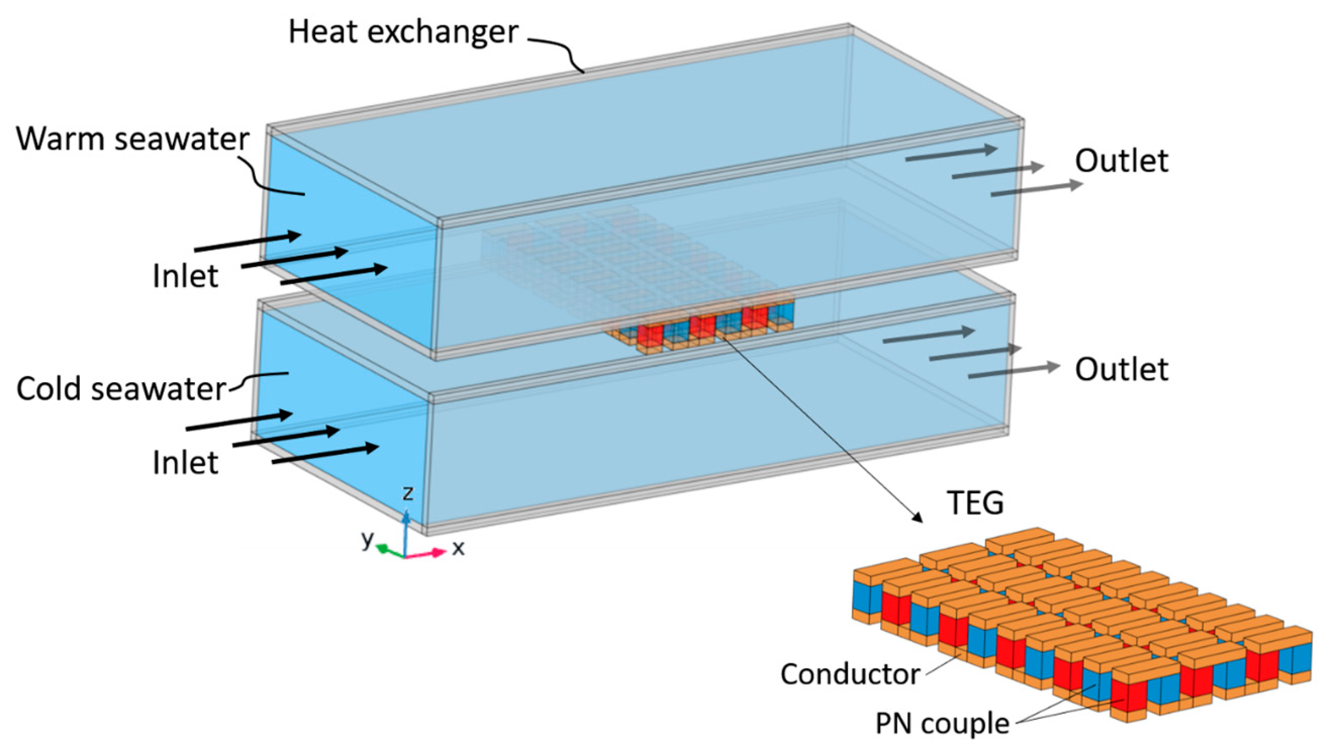
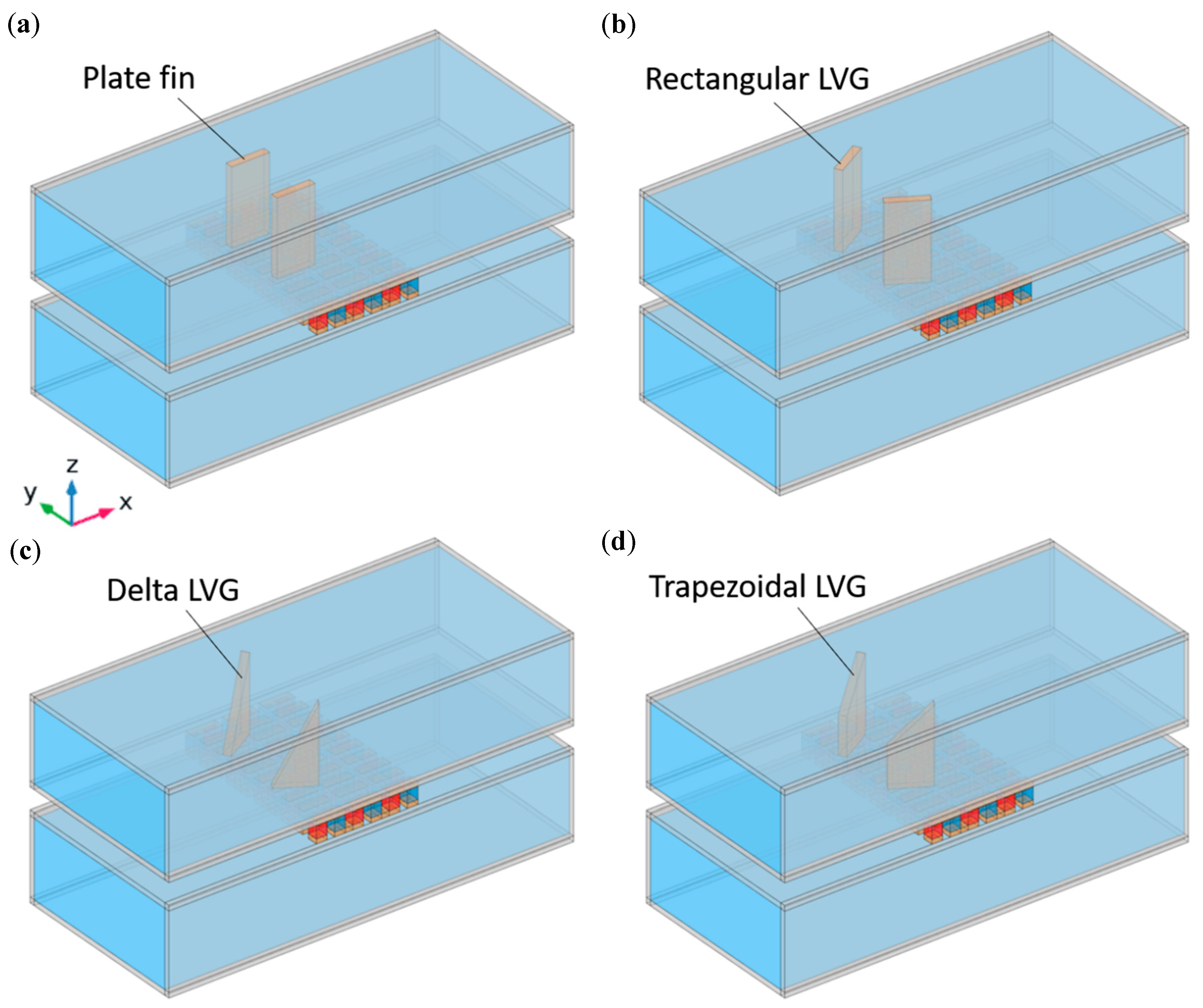
2.1. Structural, Material, and Dimensional

The schematic representation of the assembly comprising the TEG and heat exchangers is illustrated in Figure 1. The TEG is strategically located between two heat exchangers, with the upper heat exchanger serving to assist in the passage of warm surface seawater at 25 °C. In contrast, the lower heat exchanger conducts deep, cold saltwater at 4 °C. The heat exchangers are fabricated using alumina walls, featuring interior dimensions of 23 mm in width, 10 mm in height, 53.4 mm in length, and a thickness of 0.7 mm. The TEG consists of a total of 30 thermocouple units, wherein each unit is comprised of p-type semiconductors (specifically Bismuth Telluride, Bi2Te3), n-type semiconductors (also Bismuth Telluride, Bi2Te3), and connecting conductors made of copper. The p-type and n-type semiconductors have square cross-sectional dimensions measuring 1.4 mm × 1.4 mm and a height of 1.6 mm. The thermocouples have a separation of 1 mm between their legs, and the connecting conductor has a thickness of 0.6 mm. The material properties of the TEG and heat exchangers, such as the Seebeck coefficient, electrical conductivity, thermal conductivity, density, and heat capacity, have been obtained from the literature [26]. The material properties of saltwater, including thermal conductivity, dynamic viscosity, density, and heat capacity, are obtained from existing literature [27].
The present study examines the performance of heat exchangers, including four internal structures, namely flat-fin, rectangular LVG, triangular LVG, and trapezoidal LVG, compared to an empty cavity heat exchanger. Figure 2 presents schematic schematics of the internal structures of heat exchangers with integrated TEGs. To effectively transfer the thermal energy of the warm seawater to the TEG, fins and LVGs are positioned in the midstream area of the upper heat exchanger, directly above the TEG. Both the fins and LVGs are composed of copper. In order to conduct a comparative analysis of the effects of fins and LVGs, two specimens of each component were utilized. The rectangular LVGs have a length of 5 mm, a thickness of 1 mm, and a height equal to that of the heat exchanger. The leading edges of the LVGs are spaced 7 mm apart. In future investigations, the inclination angles of the LVGs (θ = 0, 30, 45, 60, 120, 135, and 150°) will be modified to examine the impact of vortex production on TEG performance. The flat-fin configuration corresponds to the rectangular LVG set at an inclination angle of 0°. This study investigates the effects of modifying the inclination angles and winglet shapes of the LVGs on fluid dynamics and TEG performance. Specifically, the rectangular winglets are replaced with triangular and trapezoidal shapes to examine the influence of alternative LVG configurations.

2.2. The Governing Equations

The assumptions underlying the numerical simulation in this study are as follows: The fluid introduced into the heat exchanger is characterized by a steady-state condition, meaning that its variables remain constant over time. Additionally, the fluid is incompressible and exhibits a fully developed flow, modeled using a turbulent flow model. The effects of heat radiation and convection in the vicinity of the heat exchanger and TEG are disregarded, along with the electrical and thermal resistances at the interface of the TEG materials.
The governing equations can be partitioned into distinct fluid and solid components. The equations governing mass conservation, momentum, and energy conservation for a fluid in a state of steady flow can be expressed as follows, as referenced in sources [11,22]:
ρ · u = 0
Navier-Stokes equation:
ρ u · u = p + μ 2 u
Energy conservation equation:
ρ c p u · T + · q = Q
In this context, ρ , μ , and c p represent the fluid’s density, dynamic viscosity coefficient, and specific heat, respectively, u is the velocity vector, p is the pressure, T is the temperature, and q represents the heat flux caused by conduction and radiation. In the absence of radiation effects, q = k f T , where k f is the thermal conductivity of the fluid; Q is the thermal energy generated by an internal heat source, and in the absence of an internal heat source,   Q is zero. By solving the mass conservation equation and the momentum equation, the fluid’s velocity and pressure can be determined. Then, the fluid’s temperature distribution can be calculated by substituting the velocity into the energy conservation equation.
Heat is transferred via thermal conduction to the heat exchanger tubes, fins, LVGs, and connecting conductors. The steady-state heat conduction equation is as follows:
· k s T = 0
where k s is the thermal conductivity.
For thermoelectric materials, the steady-state energy conservation equation can be written as [9,28,29]:
· q T E = Q J o u l e
The steady-state charge conservation equation can be written as:
· J = 0
where q T E is the heat flux on the surface of thermoelectric materials, and Q J o u l e is the Joule heat generated by the electric current passing through the thermoelectric materials, which can be written as Q J o u l e = J 2 / σ ; J is the electric current density, and σ is the electrical conductivity.
The coupled governing equations that dictate thermoelectric behavior [9,28,29] are:
q T E = S T J k T
J = σ E S T
where S , k , and σ represent the Seebeck coefficient, thermal conductivity, and electrical conductivity of the thermoelectric materials, respectively, and E is the electric field, which can be represented by the electric potential gradient V . Hence, the second constitutive equation can be rewritten as J = σ V + S T .
By substituting the thermoelectric coupled constitutive equations into the energy conservation and charge conservation equations, we can derive the following equations:
· S T J · k T = J 2 σ
· σ V + · σ S T = 0
These two equations represent the coupled relationship between electric potential and temperature. When a specific electric current is input, the electric potential and temperature distribution in the thermoelectric materials can be solved using these equations; similarly, when a specific temperature is input, the electric current and electric potential distribution in the thermoelectric materials can be determined.

2.3. Boundary Conditions

This study’s boundary conditions for the numerical simulations are as follows. The inlet of the heat exchanger is set as a fully developed flow, with a given average flow velocity and temperature of the input fluid. The outlet of the heat exchanger is set with zero pressure. The external surfaces of the heat exchanger are adiabatic, and for the TEG surfaces, apart from the hot-end and cold-end interfaces, all other surfaces are adiabatic. All solid walls are no-slip boundaries. In the TEG module, the leg of the first thermocouple on the far right is grounded, while all other boundaries of the TEG are set to be electrically insulated.

2.4. Performance Evaluation Parameters

This study defines the evaluation parameters related to the thermoelectric performance of TEGs [10,30,31] as follows. The internal resistance R p n of a thermocouple can be written as:
R p n = ρ p L p A p + ρ n L n A n
The thermal conductivity Κ of a thermocouple can be written as:
K = λ p A p L p + λ n A n L n
where ρ p and ρ n are the electrical resistivities of P-type and N-type thermoelectric materials, respectively, L p and L n are the lengths of P-type and N-type thermoelectric materials, respectively, A p and A n are the cross-sectional areas of P-type and N-type thermoelectric materials, respectively, and λ p and λ n are the thermal conductivities of P-type and N-type thermoelectric materials, respectively.
The Seebeck coefficient α p n of a thermocouple can be written as:
α p n = α p α n
where α p and α n are the Seebeck coefficients of P-type and N-type thermoelectric materials, respectively.
For TEG, the internal resistance R T E G and the open-circuit output voltage V o c can be written as:
R T E G = N R p n + 2 ρ c L c A c
V o c = N α p n T h T c
where N is the number of thermocouples in the TEG, ρ c , L c , and A c are the resistivity, length, and cross-sectional area of the connecting conductor, respectively, and T h and T c are the temperatures of the hot and cold ends of the TEG, respectively. To estimate the output power P of the TEG, an external load resistance R L is connected to form a closed-circuit current I , as follows:
I = V o c R T E G + R L
P = I 2 R L
From the above two equations, the output power can be written as:
P = V o c R T E G + R L 2 R L
When the external load resistance is equal to the internal resistance, the TEG has the maximum output power, P m a x , which can be written as:
P m a x = V o c 2 4 R T E G
The net power W n e t of the TEG is:
W n e t = P m a x W p u m p
where W p u m p is the pumping power required for the heat exchanger, which can be written as W p u m p = v i n A t u b e Δ p ; v i n is the input flow rate, A t u b e is the flow channel cross-sectional area of the heat exchanger, and Δ p is the pressure drop between the outlet and inlet. The heat absorbed by the hot end of the TEG Q h can be written as:
Q h = α p n I T h + Κ T h T c 1 2 I 2 R T E G
By comparing the net output power with the absorbed heat, the thermoelectric conversion efficiency η of the TEG can be estimated as:
η = W n e t Q h

2.5. Simulation Method

In this study, a three-dimensional physical model was established using the commercial software COMSOL, based on the finite element method (FEM) [32]. The modules utilized include the turbulent flow module, heat transfer module, electric current module, and thermoelectric effect. The governing equations were discretely solved using the finite element method. The k-ε turbulence model was employed to address turbulence issues for turbulent flow. Fluid dynamics were solved using the GMRES (generalized minimum residual) Iterative Solver. Heat transfer was managed using the PARADISO (parallel sparse direct solver) solver, and electric current issues were resolved with an algebraic multigrid iterative solver. The convergence criteria were set to a relative tolerance of less than 0.001.
Mesh configuration involved a physics-controlled mesh, with the overall computational domain constructed using a tetrahedral mesh. Near the heat exchanger walls, a five-layer boundary mesh was established. A two-dimensional view of the mesh is illustrated in Figure 3. The range of mesh counts used for the four different structures in this study was approximately 5.6 × 10⁵ to 5.7 × 10⁵. Detailed descriptions of mesh count convergence and model validation are provided in subsequent sections.

2.6. Convergence Test

The numerical simulation in this study was conducted using the finite element method (FEM) software COMSOL [32]. Prior to initiating the main analysis, convergence tests were performed on the structures under investigation to assess the impact of grid density on the FEM calculations. The outcomes of these tests are summarized in Table 1, which presents the relative inaccuracies observed in the computational results of the four configurations at different grid densities.
For this study, specific grid quantities were chosen for each configuration to strike an optimal balance between solution accuracy and computational cost. The details of the grid usage are as follows:
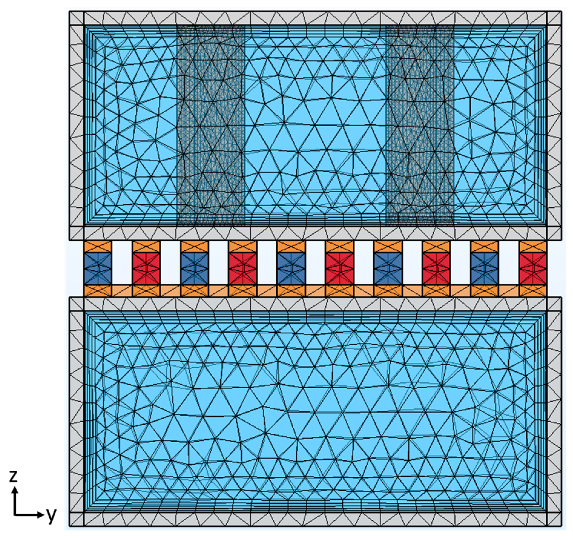
  • The TEG in the heat exchanger with flat fins utilized approximately 560,000 grids.
  • The heat exchangers with rectangular LVGs, triangular LVGs, and trapezoidal LVGs employed approximately 560,000, 590,000, and 570,000 grids, respectively.
The relative errors for the computational outcomes of the configurations with flat fins, rectangular LVGs, triangular LVGs, and trapezoidal LVGs were maintained below 4.4%, 2.1%, 2.6%, and 3.2%, respectively. This careful selection of grid densities ensures the simulation results are accurate and computationally efficient.

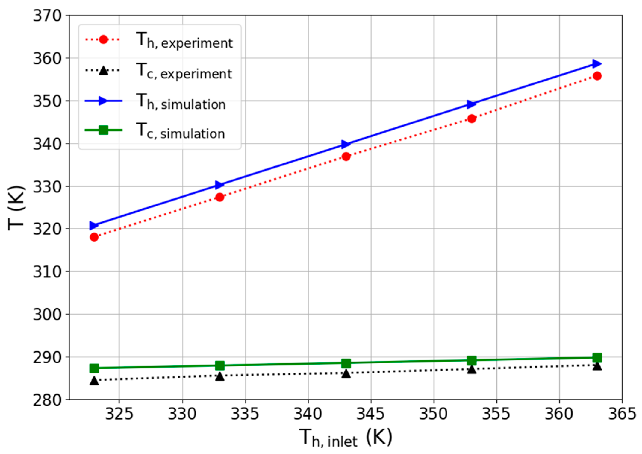
2.7. Model Validation

To ensure the reliability of the simulation method used in this study, we compared our simulation results with experimental data from the literature. Specifically, we referenced the measurements by Li et al. [33], who recorded the temperatures of a thermoelectric generator (TEG) installed between two heat exchangers. Figure 4 presents the temperature distribution at the hot and cold ends of the TEG. The operating conditions were set so that both heat exchangers received fluid at a constant flow rate of 1.3 m/s. The temperature of the fluid entering the cold end heat exchanger was fixed at 285 K, while the temperature of the fluid entering the hot end heat exchanger varied from 323 K to 363 K (in increments of 323 K, 333 K, 343 K, 353 K, and 363 K).
The results showed that the average temperatures at the hot and cold ends of the simulated TEG closely matched the experimental data, with relative errors within 1%. This verification demonstrates the reliability of the simulation methods used in our study.

3. Results and Discussion

To comprehend the impact of fins and LVGs with varying shapes on the thermoelectric conversion efficiency of TEGs within heat exchangers, the following analytical procedures were undertaken in this investigation:
First, the fluid properties of heat exchangers with flat fins, rectangular LVGs, triangular LVGs, and trapezoidal LVGs were analyzed, assuming a constant average inlet velocity. Subsequently, the average inlet velocity of the warm seawater entering the heat exchanger was varied to examine the impact of the structures above on the thermoelectric conversion performance of TEGs under different Reynolds number operating conditions.

3.1. Fluid Dynamics Analysis

Initially, the fluid characteristics of the four heat exchanger configurations were examined while maintaining a constant average inlet velocity at the inlet of the heat exchanger. The average velocity of the warm and cold seawater was 1 m/s.
The fluid velocity and streamline distributions in the heat exchanger with flat fins are depicted in Figure 5. To illustrate the impact of fins on the fluid flow, the velocity and streamline distribution data show outcomes pertaining only to the upper surface of the heat exchanger. Figure 5a shows that a well-defined velocity boundary layer adjacent to the tube wall is evident in the incoming flow region upstream of the heat exchanger. When the fluid encounters the fins within the heat exchanger, the flow velocity between the fins increases due to the reduced cross-sectional area. Additionally, the fins introduce flow resistance, decreasing velocity downstream.
Figure 5b shows that when fluid in the central region meets the fins, it maintains forward motion along the fin surfaces. This facilitates heat transfer from the fluid to the TEG below via conduction.
The fluid velocity distribution and streamline patterns in a heat exchanger equipped with rectangular LVGs are presented in Figure 6. Figure 6a shows the velocity distribution previously analyzed. Near the upstream pipe wall of the heat exchanger, a lower velocity indicates the presence of a boundary layer. As the fluid flows through the rectangular LVGs in the heat exchanger’s midsection, it undergoes a significant change in velocity due to flow resistance. The velocity is notably higher in the central region and along the lateral edges of the rectangular LVGs, whereas it is lower behind these generators.
The x–y cross-sectional analysis showed that the triangular LVG region created by the vortex generators significantly influences the velocity compared to flat plate fins. This change in velocity also disrupts the velocity boundary layer, thinning it near the pipe wall as the fluid moves past the rectangular LVGs.
Figure 6b illustrates the streamline distribution, highlighting how some streamlines form three-dimensional vortices in the presence of the rectangular LVGs. The observed streamline and velocity distributions show that vortices correspond to lower velocities, while regions without vortices display high velocities.
The vortices generated by the LVGs affect the flow in two main ways: (1) they alter the initial velocity boundary layer, and (2) they disturb the thermal boundary layer, thereby enhancing heat transfer [12]. These vortices transfer heat to the TEG below, affecting thermoelectric conversion efficiency.
Figure 7 demonstrates the flow rate and pattern of streamlines in a heat exchanger with three triangular LVGs. Figure 7a shows the velocity distribution, while Figure 7b displays the streamlines. A noticeable velocity change occurs as the fluid flows over the triangular LVGs in the central region of the heat exchanger. The velocity decreases downstream of the triangular vortex generators due to induced vortices.
The x–y cross-section analysis indicated that the velocity impact near the TEG pipe wall is significantly lower with triangular vortex generators than rectangular ones. This difference is attributed to the smaller surface area of the triangular vortex generators, which reduces the vortex generation region.
In the x–z plane, the streamlined distribution analysis showed that vortices induced by the triangular vortex generators are primarily concentrated in the lower triangle region and decrease in intensity towards the top.
Figure 8 shows the fluid velocity and streamline distributions in a heat exchanger fitted with trapezoidal LVGs. Figure 8a presents the velocity distribution, while Figure 8b illustrates the streamline distribution. The vortices induced by the trapezoidal LVGs significantly alter downstream velocities. The analysis of the velocity distribution’s x–y cross-sectional plane showed that the pipe wall velocity modification region near the TEG is more extensive with trapezoidal LVGs than triangular ones. Furthermore, the x–z plane’s streamline distribution showed that trapezoidal LVGs produce vortices over a greater area than triangular LVGs. This arises from the marginally larger surface area of trapezoidal versus triangular LVGs. The analysis of assorted LVG shapes’ flow velocities and streamlines demonstrated that geometry notably impacts velocity and vortex strength alterations.
Consequently, integrating various LVG shapes into heat exchangers can affect heat transfer efficiency. The following investigation assesses the impacts of heat exchangers equipped with different LVG configurations on TEG thermoelectric conversion performance.
The temperature unevenness at the TEG surfaces can cause thermoelectric mismatch effects, which affect TEG performance [34]. In this study, the operating temperature of the warm seawater is close to room temperature, at approximately 300 K. Simulation results indicated that the temperature difference at the TEG’s hot end is less than 0.4 K. Consequently, in the parameter calculations of this study, the thermal mismatch effect is not considered. The TEG’s hot and cold ends are characterized by their average temperatures. This approach simplifies the analysis and is justified by the minimal temperature differential observed in the simulation, suggesting a negligible impact of thermoelectric mismatch under these specific conditions.

3.2. TEG Performance Analysis

To examine the impact of fluid Reynolds numbers on the thermoelectric conversion efficiency of a TEG, this study varied the average velocity of warm inlet seawater, thereby manipulating the Reynolds number. Initially, laminar conditions were not emphasized due to enhanced heat transfer effects in turbulent flow [12]. Considering the discrepancy in channel flow Reynolds numbers between turbulent and laminar regimes [35], the velocity range studied was 0.2–1.0 m/s, yielding Reynolds numbers of 2940.2 to 14,701. TEG performance metrics included maximum output power, pumping power requirements, net power, and thermal conversion efficiency.
Heat exchangers were modeled with flat fins, rectangular LVGs, and triangular LVGs, as shown in Figure 9. The black line denotes the empty cavity heat exchanger. Colored lines signify triangular LVGs at various angles θ (30–150°). Dashed lines indicate rectangular LVGs at several angles θ (0–150°), where θ = 0° represents flat fins. Figure 9a shows that TEG output power rises with increasing Reynolds numbers. Additionally, rectangular and triangular LVG heat exchangers boosted output versus the empty cavity. Through a comparison of geometries at equal angles, θ showed that reduced vortex extent for triangular LVGs disturbs boundary layers less effectively, consistent with prior analyses of flow velocities and streamlines, thereby exhibiting lower output power.
Figure 9b indicates minimal pressure drop changes at lower Reynolds numbers. However, intensifying changes at higher Reynolds numbers require substantially more pumping power. At identical θ, lower resistance in triangular LVGs reduces pressure drops and pumping requirements more than rectangular LVGs. Flat fins and empty cavities require the least pumping power.
Figure 9c,d exhibit comparable TEG net output and conversion efficiency trends, respectively. Although rectangular LVGs elevate output, associated pumping power prompts sharp declines in efficiency with rising Reynolds numbers. Conversely, modest pumping needs for triangular LVGs minimize efficiency reductions at lower Reynolds numbers than rectangular types.
In summary, at 0.2 m/s (Reynolds number 2940.2), TEG efficiency for rectangular and triangular LVG heat exchangers is substantially higher than that of empty cavities. Configurations that optimize efficiency feature flat fins with 30° rectangular LVGs or 45–60° triangular LVGs. Thus, triangular LVGs mitigate the substantial pumping requirements of rectangular LVGs, but limited output power restricts exceeding the peak efficiency of optimized rectangular LVG designs. The ideal enhancement would enhance vortex intensity to elevate output power while preserving minimal fluid resistance and pumping energy.
Figure 10 depicts the thermoelectric conversion parameters of thermoelectric generators (TEGs) installed in heat exchangers with flat fins, rectangular LVGs, and trapezoidal LVGs. The black solid line represents an empty cavity heat exchanger, while colored solid lines indicate trapezoidal generators at various inclination angles (θ = 30, 45, 60, 120, 135, and 150°). The dashed lines signify rectangular generators at different angles (θ = 0, 30, 45, 60, 120, 135, and 150°), where θ = 0° corresponds to flat fins. Figure 10a illustrates the TEG output power. Compared to triangular generators in Figure 9a, trapezoidal ones demonstrate enhanced output capacity due to a larger surface area and more robust vortex effects. However, the slightly higher drag of the trapezoidal design necessitates additional pumping power, as shown in Figure 10b. Figure 10c,d depict the TEG net output power and thermoelectric conversion efficiency, respectively. Trapezoidal LVGs achieve superior conversion efficiency at equal inclination angles over rectangular LVGs.
To comprehensively assess the influence of inclination angle on the thermoelectric conversion performance of TEGs with various LVG shapes, our investigation primarily focused on the operational state exhibiting maximum thermoelectric conversion efficiency. This corresponds to a flow velocity of 0.2 m/s with a Reynolds number of 2940.2. The analysis focused on the impacts of inclination angle on rectangular, triangular, and trapezoidal LVGs at this flow velocity, as depicted in Figure 11. The dashed line denotes flat fins, while solid lines represent the three LVG configurations: rectangular, triangular, and trapezoidal. Figure 11a,b illustrate output and pumping power values, respectively. The findings demonstrate that for both slight (θ = 30, 45, 60°) and steep (θ = 120, 135, 150°) inclination angles, output power and pumping power escalate as the angle approaches 90°. Additionally, shallow angles (θ = 30, 45, 60°) confer greater output power than steep angles (θ = 120, 135, 150°), enhancing TEG conversion efficiency. A comparison of the different shapes shows that triangular generators have the lowest output and pumping power, while rectangular ones exhibit the highest without achieving maximum efficiency. Alternatively, the trapezoidal design balances output and pumping power more effectively than rectangular and triangular configurations. Consequently, trapezoidal LVGs inclined at 30° demonstrate superior conversion efficiency over conventional flat fins.

4. Conclusions

The LVGs produce vortices that disrupt boundary layers and enhance heat transfer. Furthermore, integrating LVGs and heat exchangers can improve the thermoelectric conversion efficiency of TEGs beyond their applications in thermal fluid systems. The primary objective of this study was to examine the influence of various geometries of winglet-type LVGs on the thermoelectric conversion efficiency of TEGs implemented in OTEC systems.
Using a numerical simulation, this study aimed to evaluate the impact of different heat exchanger designs—including flat fins, rectangular, triangular, and trapezoidal LVGs—on the thermoelectric conversion performance of TEGs. Fluid dynamic characteristics were examined for heat exchangers with four internal structures, focusing on fluid velocity and streamline distributions. Moreover, by installing TEGs in the four heat exchangers, thermoelectric conversion performance was assessed across various Reynolds numbers based on critical metrics such as maximum output power, pumping power, net output power, and conversion efficiency.
The key findings are summarized as follows:
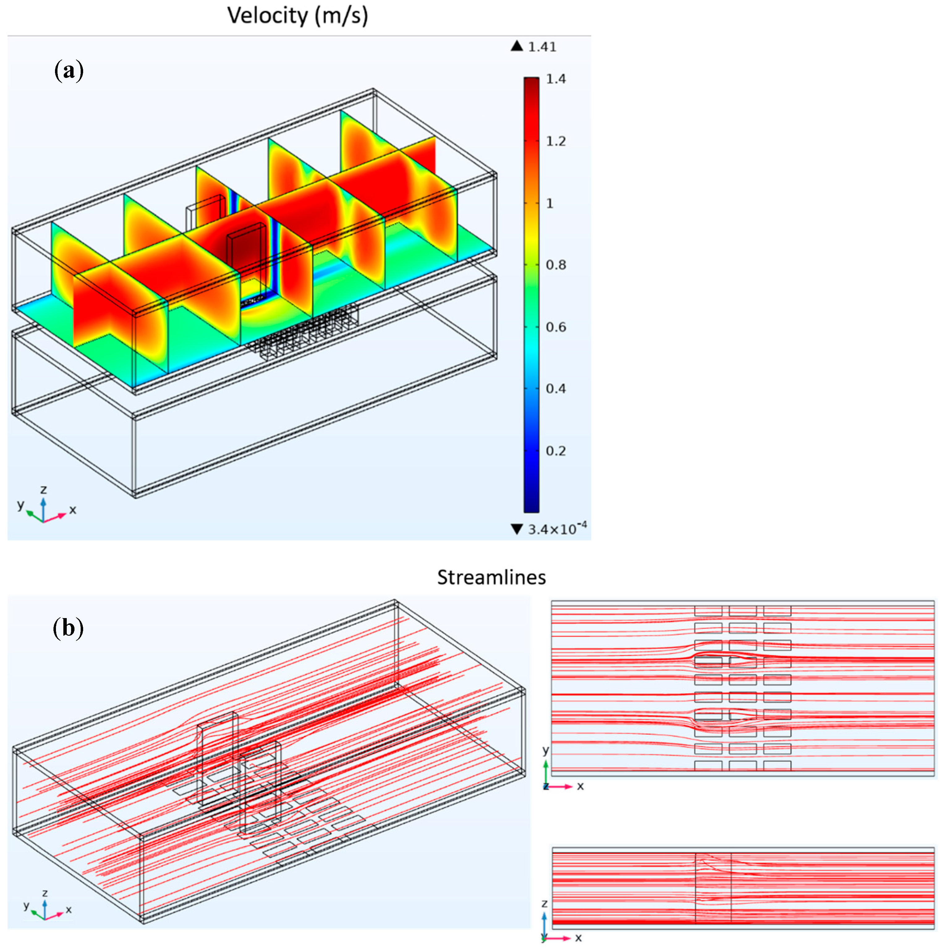
  • An analysis of flow velocity distributions and streamlines showed that flow velocities notably decrease in heat exchanger areas influenced by LVGs while faster speeds persist in vortex-free regions. The vortices can disrupt the original boundary layer thickness, enabling heat transfer to the TEGs below through vortex effects, thereby impacting TEG thermoelectric conversion performance.
  • An analysis of heat exchangers with LVGs of varying geometries showed that vortex generator shape significantly impacts flow velocity changes and vortex strength. Rectangular vortex generators affect a much wider area than flat fins, markedly thinning the boundary layer as fluid flows past them near the pipe wall.
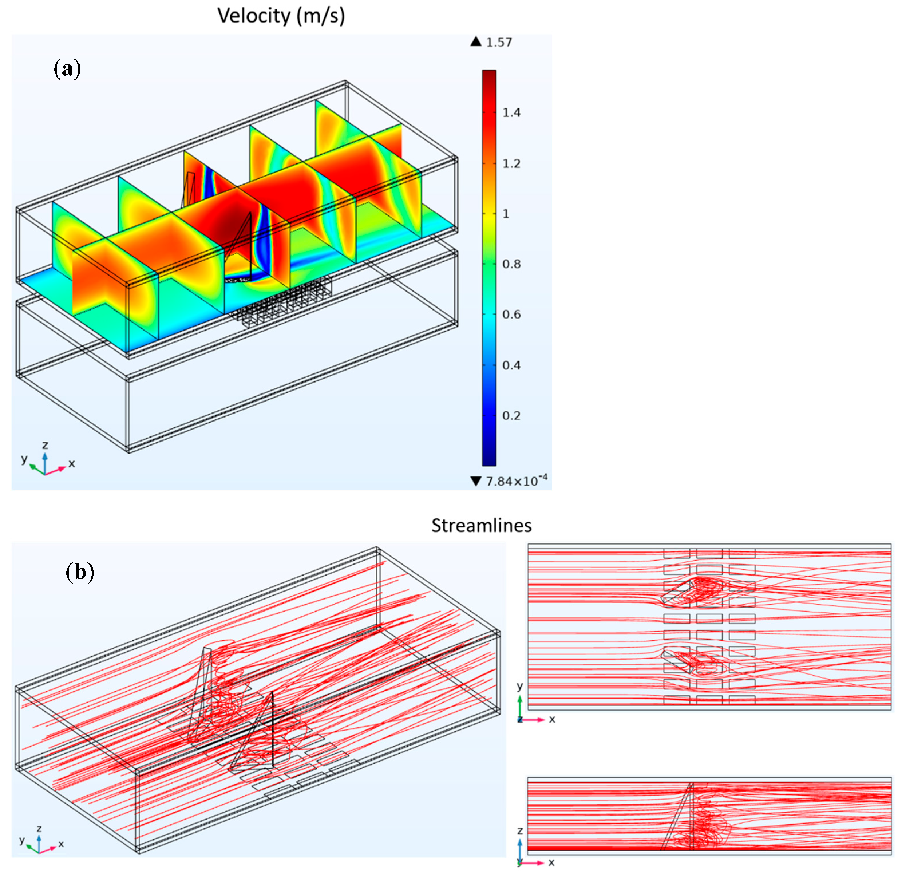
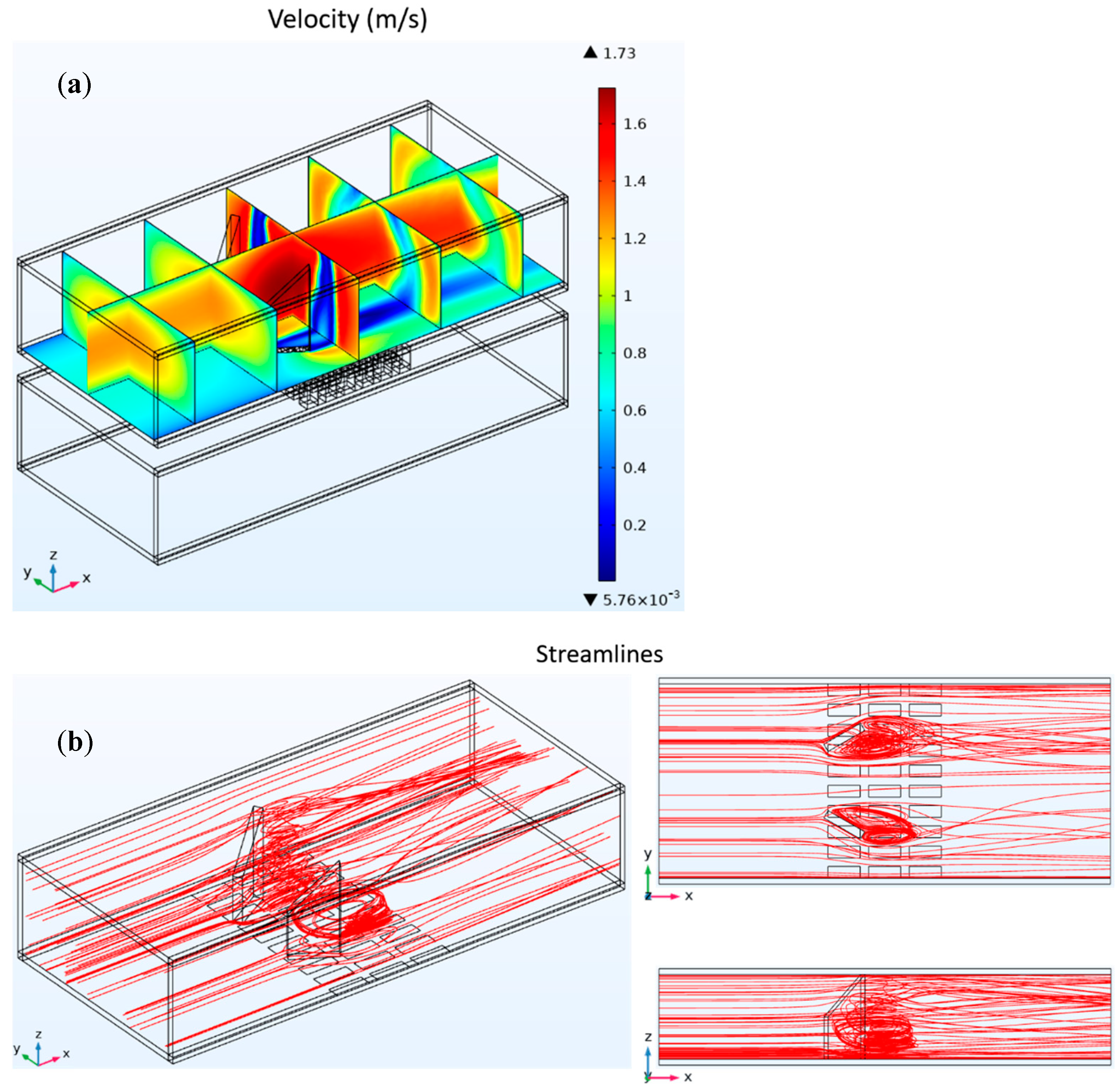
  • Due to their smaller surface area, triangular vortex generators produce vortices over a smaller region versus rectangular ones, concentrated in the lower half, with weakening vorticity approaching the upper end. Having a slightly greater area, trapezoidal vortex generators influence flow velocities and vortex generation over a broader area than triangular ones.
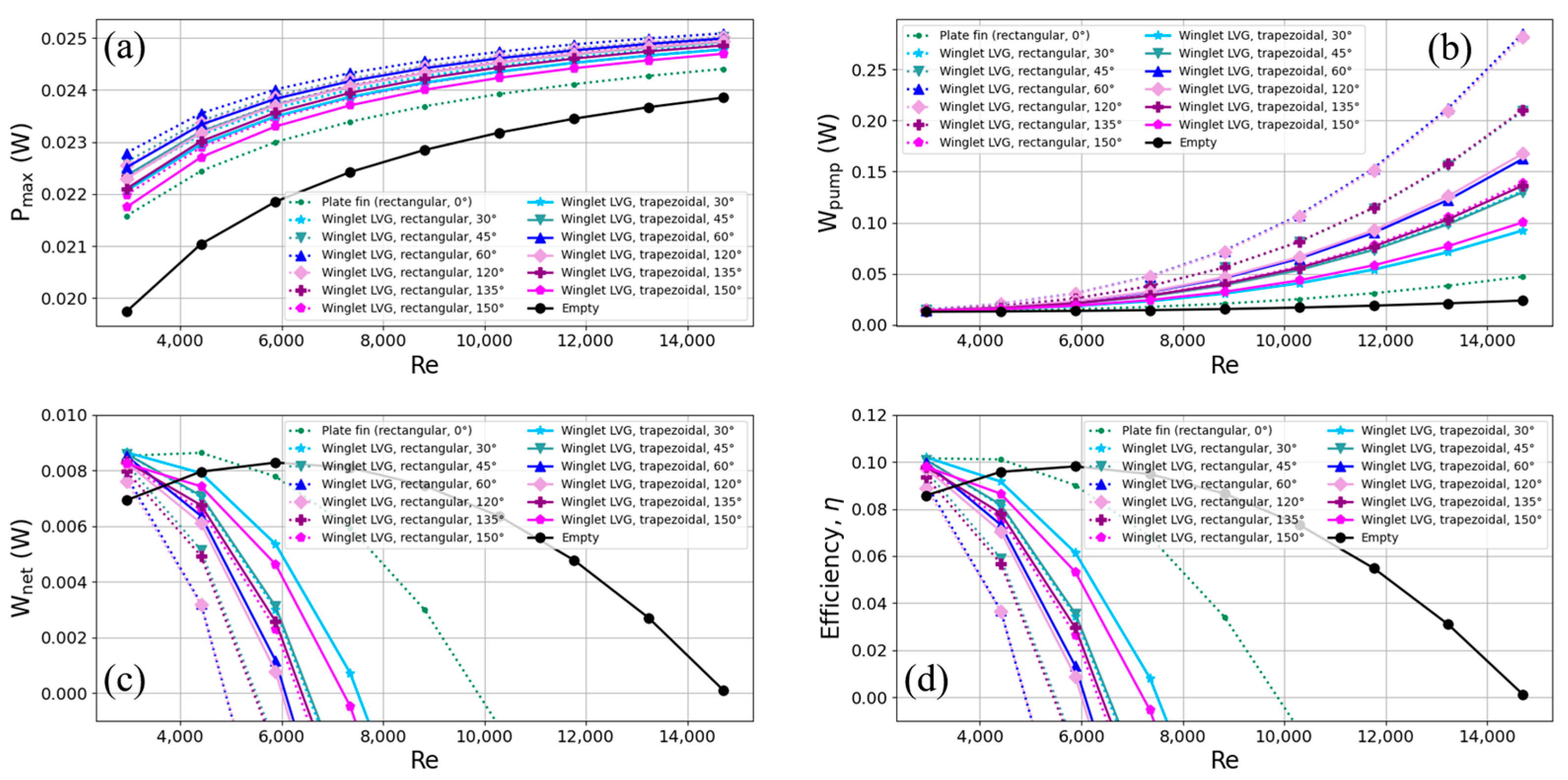
  • All four heat exchanger internal structures—flat fins, rectangular, triangular, and trapezoidal LVGs—enabled higher TEG output power over the empty cavity type. However, the greater pumping power required with vortex generators causes TEG conversion efficiency to sharply decline with rising Reynolds numbers.
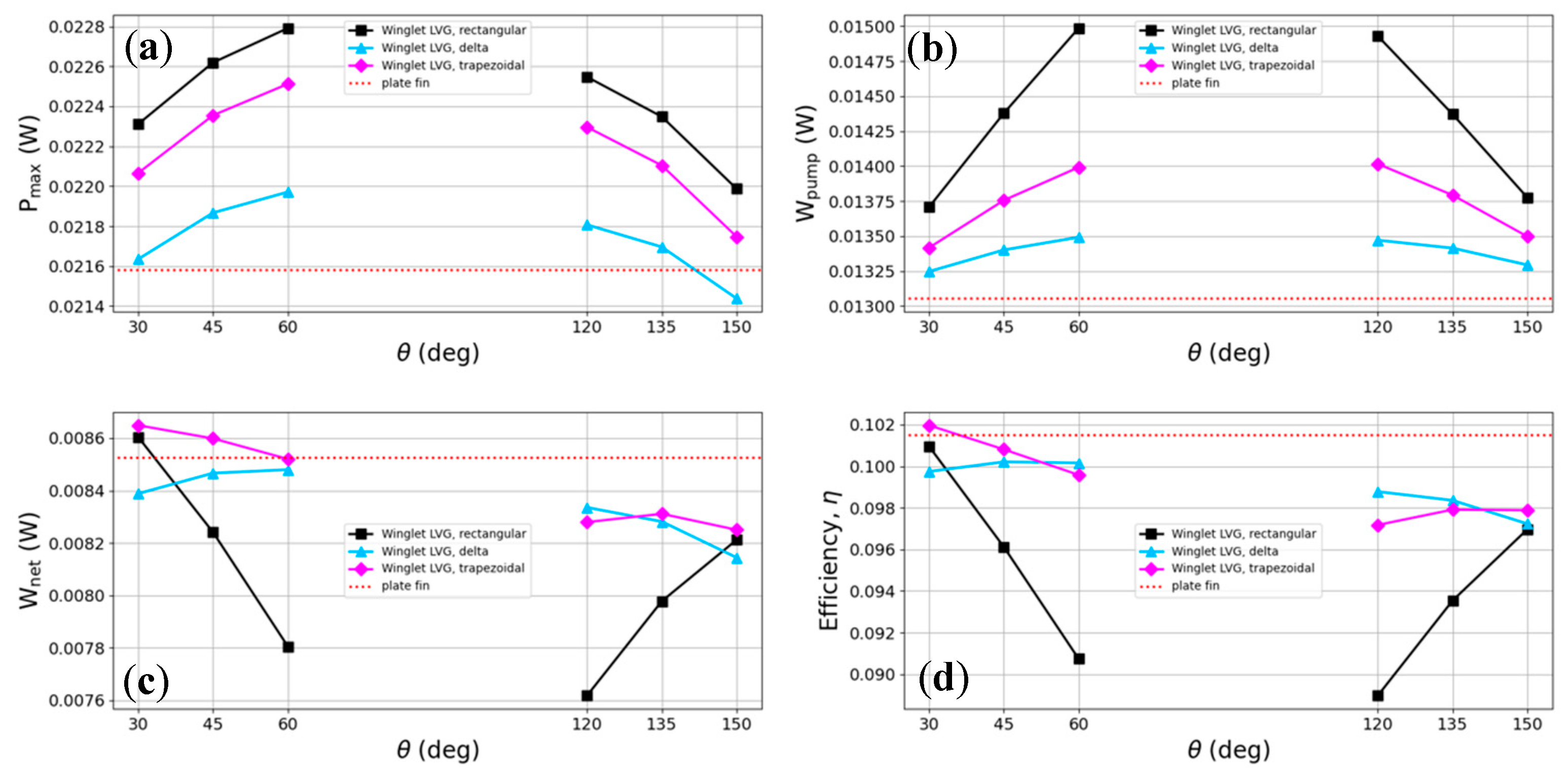
  • While triangular vortex generators mitigate the high pumping power of rectangular ones, insufficient output power prevents them from exceeding the efficiency of flat fins or 30° rectangular vortex generators. Compared to triangular generators, trapezoidal ones improve output power and achieve superior conversion efficiency at the same inclination angles as rectangular vortex generators.
  • At 0.2 m/s flow velocity (Re = 2940.2), TEG conversion efficiency achieved higher levels with LVG heat exchangers over the empty cavity type. Increasing the inclination angle toward 90° boosts both output and pumping power. Moreover, shallow angles (θ = 30, 45, and 60°) confer greater output power over steep angles (θ = 120, 135, and 150°) for improved TEG conversion efficiency.
  • In conclusion, trapezoidal LVGs attain a better balance between output and pumping power than rectangular and triangular configurations. Hence, trapezoidal vortex generators inclined at 30° attain maximum conversion efficiency, exceeding flat fins.
  • This study neglected the thermal mismatch effect due to the relatively low operating temperatures. However, it is essential to note that the uneven temperature distribution causing thermal mismatch could become more pronounced as operating temperatures increase. This issue is significant for thermoelectric components in numerical computations and practical applications. It is believed that considering the impact of thermal mismatch on thermoelectric performance represents a worthwhile direction for future research. This aspect could yield crucial insights for developing and optimizing thermoelectric systems, especially in high-temperature environments.

Author Contributions

Conceptualization, C.-I.W. and Y.-C.C.; methodology, C.-I.W. and Y.-C.C.; software, Y.-C.C.; validation, Y.-C.C.; formal analysis, C.-I.W. and Y.-C.C.; investigation, C.-I.W. and Y.-C.C.; resources, C.-I.W.; data curation, Y.-C.C.; writing—original draft preparation, C.-I.W. and Y.-C.C.; writing—review and editing, C.-I.W.; visualization, Y.-C.C.; supervision, C.-I.W.; project administration, C.-I.W.; funding acquisition, C.-I.W. All authors have read and agreed to the published version of the manuscript.

Funding

This research was funded by the National Science and Technology Council of Taiwan, grant number 111-2221-E-019-060.

Data Availability Statement

The original contributions presented in this study are included in the article; further inquiries can be directed to the corresponding author.

Conflicts of Interest

The authors declare no conflicts of interest.

References

  1. Hooshmand Zaferani, S.; Jafarian, M.; Vashaee, D.; Ghomashchi, R. Thermal Management Systems and Waste Heat Recycling by Thermoelectric Generators—An Overview. Energies 2021, 14, 5646. [Google Scholar] [CrossRef]
  2. Energy Flow Charts. Available online: https://flowcharts.llnl.gov/commodities/energy (accessed on 17 October 2023).
  3. Hasan, A.; Dincer, I. An ocean thermal energy conversion based system for district cooling, ammonia and power production. Int. J. Hydrogen Energy 2020, 45, 15878–15887. [Google Scholar] [CrossRef]
  4. Khan, N.; Kalair, A.; Abas, N.; Haider, A. Review of ocean tidal, wave and thermal energy technologies. Renew. Sustain. Energy Rev. 2017, 72, 590–604. [Google Scholar] [CrossRef]
  5. Kim, A.S.; Kim, H.-J.; Lee, H.-S.; Cha, S. Dual-use open cycle ocean thermal energy conversion (OC-OTEC) using multiple condensers for adjustable power generation and seawater desalination. Renew. Energy 2016, 85, 344–358. [Google Scholar] [CrossRef]
  6. Faizal, M.; Ahmed, M.R. Experimental studies on a closed cycle demonstration OTEC plant working on small temperature difference. Renew. Energy 2013, 51, 234–240. [Google Scholar] [CrossRef]
  7. Bohn, M.S.; Benson, D.K.; Jayadev, T.S. Thermoelectric ocean thermal energy conversion. J. Sol. Energy Eng. 1980, 102, 119–127. [Google Scholar] [CrossRef]
  8. Champier, D. Thermoelectric generators: A review of applications. Energy Convers. Manage. 2017, 140, 167–181. [Google Scholar] [CrossRef]
  9. Zhang, Q.-H.; Bai, S.-Q.; Chen, L.-D. Technologies and Applications of Thermoelectric Devices: Current Status, Challenges and Prospects. J. Inorg. Mater. 2019, 34, 279–293. [Google Scholar] [CrossRef]
  10. Jaziri, N.; Boughamoura, A.; Müller, J.; Mezghani, B.; Tounsi, F.; Ismail, M. A comprehensive review of Thermoelectric Generators: Technologies and common applications. Energy Rep. 2020, 6, 264–287. [Google Scholar] [CrossRef]
  11. Yan, S.-R.; Moria, H.; Asaadi, S.; Sadighi Dizaji, H.; Khalilarya, S.; Jermsittiparsert, K. Performance and profit analysis of thermoelectric power generators mounted on channels with different cross-sectional shapes. Appl. Therm. Eng. 2020, 176, 5455. [Google Scholar] [CrossRef]
  12. Liu, C.; Teng, J.-t.; Chu, J.-C.; Chiu, Y.-l.; Huang, S.; Jin, S.; Dang, T.; Greif, R.; Pan, H.-H. Experimental investigations on liquid flow and heat transfer in rectangular microchannel with longitudinal vortex generators. Int. J. Heat Mass Transfer 2011, 54, 3069–3080. [Google Scholar] [CrossRef]
  13. Liu, S.; Sakr, M. A comprehensive review on passive heat transfer enhancements in pipe exchangers. Renew. Sustain. Energy Rev. 2013, 19, 64–81. [Google Scholar] [CrossRef]
  14. Jacobi, A.M.; Shah, R.K. Heat transfer surface enhancement through the use of longitudinal vortices: A review of recent progress. Exp. Therm Fluid Sci. 1995, 11, 295–309. [Google Scholar] [CrossRef]
  15. Fiebig, M. Embedded vortices in internal flow: Heat transfer and pressure loss enhancement. Int. J. Heat Fluid Flow 1995, 16, 376–388. [Google Scholar] [CrossRef]
  16. Tian, L.-T.; He, Y.-L.; Lei, Y.-G.; Tao, W.-Q. Numerical study of fluid flow and heat transfer in a flat-plate channel with longitudinal vortex generators by applying field synergy principle analysis. Int. Commun. Heat Mass Transfer 2009, 36, 111–120. [Google Scholar] [CrossRef]
  17. Li, H.-Y.; Chen, C.-L.; Chao, S.-M.; Liang, G.-F. Enhancing heat transfer in a plate-fin heat sink using delta winglet vortex generators. Int. J. Heat Mass Transfer 2013, 67, 666–677. [Google Scholar] [CrossRef]
  18. Skullong, S.; Promthaisong, P.; Promvonge, P.; Thianpong, C.; Pimsarn, M. Thermal performance in solar air heater with perforated-winglet-type vortex generator. Sol. Energy 2018, 170, 1101–1117. [Google Scholar] [CrossRef]
  19. Berber, A.; Gürdal, M.; Yetimoğlu, M. Experimental study on the heat transfer enhancement in a rectangular channel with curved winglets. Exp. Heat Transfer 2021, 35, 797–817. [Google Scholar] [CrossRef]
  20. Weng, C.-C.; Huang, M.-J. A simulation study of automotive waste heat recovery using a thermoelectric power generator. Int. J. Therm. Sci. 2013, 71, 302–309. [Google Scholar] [CrossRef]
  21. Bai, S.; Lu, H.; Wu, T.; Yin, X.; Shi, X.; Chen, L. Numerical and experimental analysis for exhaust heat exchangers in automobile thermoelectric generators. Case Stud. Therm. Eng. 2014, 4, 99–112. [Google Scholar] [CrossRef]
  22. Ma, T.; Lu, X.; Pandit, J.; Ekkad, S.V.; Huxtable, S.T.; Deshpande, S.; Wang, Q.-W. Numerical study on thermoelectric–hydraulic performance of a thermoelectric power generator with a plate-fin heat exchanger with longitudinal vortex generators. Appl. Energy 2017, 185, 1343–1354. [Google Scholar] [CrossRef]
  23. Garud, K.S.; Seo, J.-H.; Patil, M.S.; Bang, Y.-M.; Pyo, Y.-D.; Cho, C.-P.; Lee, M.-Y. Thermal–electrical–structural performances of hot heat exchanger with different internal fins of thermoelectric generator for low power generation application. J. Therm. Anal. Calorim. 2021, 143, 387–419. [Google Scholar] [CrossRef]
  24. Chen, W.-H.; Wang, C.-M.; Huat Saw, L.; Hoang, A.T.; Bandala, A.A. Performance evaluation and improvement of thermoelectric generators (TEG): Fin installation and compromise optimization. Energy Convers. Manage. 2021, 250, 4858. [Google Scholar] [CrossRef]
  25. Hassan, M.A.; Samanta, R. Heat Exchanger Assisted Exhaust Heat Recovery with Thermoelectric Generator in Heavy Vehicles. Energy Technol. 2021, 9, 37. [Google Scholar] [CrossRef]
  26. Prasad, A.; Thiagarajan, R.C. Multiphysics Modeling and Multilevel Optimization of Thermoelectric Generator for Waste Heat Recovery. In Proceedings of the COMSOL Conference, Bangalore, India, 9–10 August 2018; pp. 1–7. [Google Scholar]
  27. The Engineering ToolBox. Seawater—Properties. Available online: https://www.engineeringtoolbox.com/sea-water-properties-d_840.html (accessed on 17 October 2023).
  28. Chen, W.-H.; Lin, Y.-X.; Wang, X.-D.; Lin, Y.-L. A comprehensive analysis of the performance of thermoelectric generators with constant and variable properties. Appl. Energy 2019, 241, 11–24. [Google Scholar] [CrossRef]
  29. Sandoz-Rosado, E.J. Investigation and Development of Advanced Models of Thermoelectric Generators for Power Generation Applications; Rochester Institute of Technology: Rochester, NY, USA, 2009. [Google Scholar]
  30. Tian, H.; Sun, X.; Jia, Q.; Liang, X.; Shu, G.; Wang, X. Comparison and parameter optimization of a segmented thermoelectric generator by using the high temperature exhaust of a diesel engine. Energy 2015, 84, 121–130. [Google Scholar] [CrossRef]
  31. Kumar, S.; Heister, S.D.; Xu, X.; Salvador, J.R.; Meisner, G.P. Thermoelectric Generators for Automotive Waste Heat Recovery Systems Part I: Numerical Modeling and Baseline Model Analysis. J. Electron. Mater. 2013, 42, 665–674. [Google Scholar] [CrossRef]
  32. COMSOL Multiphysics. Available online: https://www.comsol.com/ (accessed on 17 October 2023).
  33. Li, W.; Peng, J.; Xiao, W.; Wang, H.; Zeng, J.; Xie, J.; Huang, Q.; Mao, K.; Zhang, L. The temperature distribution and electrical performance of fluid heat exchanger-based thermoelectric generator. Appl. Therm. Eng. 2017, 118, 742–747. [Google Scholar] [CrossRef]
  34. Sanin-Villa, D.; Monsalve-Cifuentes, O.D.; Henao-Bravo, E.E. Evaluation of thermoelectric generators under mismatching conditions. Energies 2021, 14, 8016. [Google Scholar] [CrossRef]
  35. Nguyen, N.-T.; Wereley, S.T. Fundamentals and Applications of Microfluidics, 2nd ed.; Artech House: Norwood, MA, USA, 2006. [Google Scholar]
Figure 1. Schematic of TEG installation in heat exchangers.
Energies 17 00526 g001
Figure 2. Schematic diagrams of TEG installations in heat exchangers with (a) flat-fin, (b) rectangular LVG, (c) triangular LVG, and (d) trapezoidal LVG.
Energies 17 00526 g002
Figure 3. Two-dimensional perspective view of the grid in the entire computational domain.
Energies 17 00526 g003
Figure 4. Temperature distribution at the hot and cold ends of the TEG: a comparison of experimental measurements [33] and simulation results.
Energies 17 00526 g004
Figure 5. Fluid velocity distribution chart (a) and streamline distribution chart (b) for heat exchangers with flat fins.
Energies 17 00526 g005
Figure 6. Fluid velocity distribution chart (a) and streamline distribution chart (b) for heat exchangers with rectangular LVGs.
Energies 17 00526 g006
Figure 7. Fluid velocity distribution chart (a) and streamline distribution chart (b) for heat exchangers with triangular LVGs.
Energies 17 00526 g007
Figure 8. Fluid velocity distribution chart (a) and streamline distribution chart (b) for heat exchangers with trapezoidal LVGs.
Energies 17 00526 g008
Figure 9. Trends in changes in (a) maximum output power, (b) pumping power, (c) net output power, and (d) thermoelectric conversion efficiency with Reynolds numbers for TEGs installed in heat exchangers with flat fins, rectangular LVGs, and triangular LVGs.
Energies 17 00526 g009
Figure 10. Trends in changes in (a) maximum output power, (b) pumping power, (c) net output power, and (d) thermoelectric conversion efficiency with Reynolds numbers for TEGs installed in heat exchangers with flat fins, rectangular LVGs, and trapezoidal LVGs.
Energies 17 00526 g010
Figure 11. Effects of different inclination angles of rectangular LVGs, triangular LVGs, and trapezoidal LVGs on (a) maximum output power, (b) pumping power, (c) net output power, and (d) thermoelectric conversion efficiency.
Energies 17 00526 g011
Table 1. Convergence test for four structures.
TypeNumber of ElementsRelative Errors
Pmax (W)Qh (W)p (Pa)Wnet (W)
Plate fin240,458−0.77%−0.33%−11.56%−12.59%
557,552−0.61%−0.26%−4.33%−3.88%
1,622,522
Rectangular LVG240,875−0.55%−0.23%−3.63%−3.14%
559,387−0.48%−0.21%−2.01%−1.75%
1,641,377
Delta LVG237,358−0.43%−0.18%−6.44%−5.98%
585,168−0.42%−0.18%−2.58%−2.12%
1,716,857
Trapezoidal LVG238,511−0.47%−0.20%−6.10%−5.72%
574,060−0.42%−0.18%−3.17%−2.91%
1,759,335
Disclaimer/Publisher’s Note: The statements, opinions and data contained in all publications are solely those of the individual author(s) and contributor(s) and not of MDPI and/or the editor(s). MDPI and/or the editor(s) disclaim responsibility for any injury to people or property resulting from any ideas, methods, instructions or products referred to in the content.

