Article

Retrofitting Biomass Combined Heat and Power Plant for Biofuel Production—A Detailed Techno-Economic Analysis †

School of Business, Society and Engineering, Mälardalen University, P.O. Box 883, 721 23 Västerås, Sweden
*
Author to whom correspondence should be addressed.
This paper is an extended version of our paper published in the 64th International Conference of Scandinavian Simulation Society, SIMS, 2023, titled “Retrofitting Biomass Combined Heat and Power Plant for Biofuel Production”.
Energies 2024, 17(2), 522; https://doi.org/10.3390/en17020522
Submission received: 28 December 2023 / Revised: 15 January 2024 / Accepted: 17 January 2024 / Published: 22 January 2024

Abstract

:
Existing combined heat and power plants usually operate on part-load conditions during low heating demand seasons. Similarly, there are boilers designated for winter use that remain inactive for much of the year. This brings a concern about the inefficiency of resource utilization. Retrofitting existing CHP plants (especially for those with spare boilers) for biofuel production could increase revenue and enhance resource efficiency. This study introduces a novel approach that combines biomass gasification and pyrolysis in a polygeneration process that is based on utilizing existing CHP facilities to produce biomethane, bio-oil, and hydrogen. In this work, a detailed analysis was undertaken of retrofitting an existing biomass combined heat and power plant for biofuel production. The biofuel production plant is designed to explore the polygeneration of hydrogen, biomethane, and bio-oil via the integration of gasification, pyrolysis, and renewable-powered electrolysis. An Aspen Plus model of the proposed biofuel production plant is established followed by a performance investigation of the biofuel production plant under various design conditions. An economic analysis is carried out to examine the profitability of the proposed polygeneration system. Results show that the proposed polygeneration system can achieve 40% carbon efficiency with a payback period of 9 years and an internal rate of return of 17.5%, without the integration of renewable hydrogen. When integrated with renewable-power electrolysis, the carbon efficiency could be significantly improved to approximately 90%; however, the high investment cost associated with the electrolyzer system makes this integration economically unfavorable.

1. Introduction

Climate change has emerged as a significant issue globally, attracting increasing attention among researchers, policymakers, and the general public. To mitigate the impacts of climate change, the International Energy Agency (IEA) proposed a net zero emissions scenario by 2025, intended to guide the clean energy transition process [1]. Various clean energy technologies, such as utilization of renewable energy, energy efficiency enhancement, and carbon capture and storage, are encouraged to facilitate the energy transition process to achieve the net-zero emissions goal [2].
Biomass has been acknowledged as a premier renewable energy resource in the EU [3], aimed at supplementing the diminishing reserves of fossil fuels. According to the prediction of the IEA, it is estimated that by 2050, up to 27% of the world’s transportation fuel can be produced through the sustainable provision of biomass and waste resources [4]. Among various biomass conversion pathways, thermochemical processes, such as gasification and pyrolysis, are capable of converting diverse feedstocks into biofuels, including forest residuals, agricultural waste products, food waste, and municipal solid waste. This flexibility of utilizing those theoretically low-cost feedstocks makes the thermochemical conversion of biomass more economically viable for biofuel production [5].
As a thermochemical pathway for biomass conversion, fast pyrolysis has the potential to be integrated into existing combined heat and power (CHP) plants [6], thereby enhancing its cost competitiveness for biofuel production. Karvonen et al. performed an environmental assessment on the integration of fast pyrolysis into a CHP plant [7]. This integration was achieved by using the heat from char and non-condensing gas combustion to enhance heat and power generation in a CHP plant. The results indicated that the efficiency of stand-alone pyrolysis was improved from 59% to 71% upon integration into a CHP plant. A study on the integration of biomass fast pyrolysis with a municipal waste CHP plant was conducted by Kohl et al. [8]. The heat required in the biomass pyrolysis process was supplied by the hot flue gas from the CHP plant in this work, aiming to improve the pyrolysis product yield and retain the district heat load simultaneously. It is noted that the operational hours of the CHP plant could be potentially increased by 57%, which makes this integration economically viable. Onarheim et al. performed a techno-economic analysis of a fast pyrolysis bio-oil production process with integration into an existing fluid bed boiler CHP plant [9]. The sand heated in the CHP plant was sent to support the endothermic reaction in the pyrolysis reactor. Sensitivity analysis on different feedstocks and varying heat and electricity prices was also implemented in this study. The results showed that the economic advantages of this integration highly depend on the cost of heat and the cost of feedstocks. Zetterholm et al. completed a comprehensive evaluation of fast-pyrolysis value-chain configurations considering different types of locations, emissions, feedstocks, and final products [10]. The results showed that the production cost for crude pyrolysis liquid is in the range of 36–60 EUR/MWh, and 61–90 EUR/MWh for upgrading to diesel and petrol. It was also found that the integration of existing industrial infrastructure helps to mitigate the production cost.
Daraei et al. investigated the integration of energy technologies, including hydrotreated pyrolysis oil production with existing CHP plants [11]. The results indicate the potential of the proposed integration to increase the system’s flexibility. Björnsson et al. evaluated the energy and greenhouse gas (GHG) performance of integrating fast pyrolysis into existing CHP plants for bio-oil production, showing that this integration could produce bio-oil with a low carbon footprint, 1.7–4.0 g CO2eq/MJLHV, and makes it attractive for the transport biofuel market [12]. A recent study by Pettersson et al. also indicates that integrating fast pyrolysis into existing CHP plants could reduce GHG emissions by up to 0.24 MtCO2-eq per year, by replacing fossil fuels in the transport sector with pyrolysis bio-oil [13]. Yang et al. carried out a techno-economic analysis of an integrated intermediate pyrolysis and CHP plant, emphasizing that particular attention should be given to the factors with significant impacts on profitability [14]. However, there are still some challenges for large commercialization of employing fast pyrolysis for biofuel production. The challenges such as the high oxygen content, instability, and corrosiveness of crude bio-oils are highlighted in a review conducted by Mostafazadeh et al. [15]. Stefanidis et al. explored the potential of co-processing bio-oil in refinery processes and highlighted the operational challenges of co-processing raw bio-oil and the need for reactor modifications for commercial-scale applications [16]. Raud et al. also emphasized the importance of enhancing production efficiency, lowering costs, and tackling issues related to feedstock variability as key steps in the commercialization of fast pyrolysis for biofuel production [17].
Various gasification technologies are also considered in the biofuel production process since they provide excellent synergies. As an energy-intensive process, biomass gasification can benefit from the integration of existing CHP plants. Piazzi et al. performed an experimental study to investigate the feasibility of retrofitting existing small-scale gasifiers from CHP production to hydrogen and biofuel generation [18]. The co-production of syngas and biofuel by using the dual fluidized bed gasifier has been examined by Gustavsson et al., showing a substantial enhancement in system efficiency [19]. The economic feasibility of complementing existing CHP plants for hydrogen production was investigated by Naqvi et al., where the estimated cost for hydrogen production is 0.125–0.75 EUR/kg [20]. Thunman et al. conducted an economic analysis of the GoBiGas plant, which is the first industrial installation for biomethane production with gasification [21]. This study found that the economic performance could be improved if integrated with existing infrastructure and low-grade feedstocks. Holmgren et al. examined the performance of gasification-based biofuel production systems with the integration of a district heating system [22]. It is concluded that the profitability of this system is strongly dependent on specific production technologies and on reference power production. The integration of existing CHP plants and the gasification process for dimethyl ether or methanol production was analyzed by Salman et al. [23]. The results showed that the profitability could be notably improved by integrating gasification with the CHP plant for biofuel production as compared with only heat and electricity generation.
Brynda et al. presented the operational results of a fixed-bed multi-stage gasifier (GP750) for decentralized CHP and biochar production, which achieved a low-tar production gas suitable for internal combustion engines and a gross electric efficiency between 29.1 and 32.9% [24]. Butera et al. explored a solution for coupling gasification with solid oxide cells (SOCs) for flexible methanol production from biomass. The study evaluated various plant configurations and operational modes, highlighting the efficiency and carbon conversion in biofuel production [25]. A study conducted by Costa et al. showed that the integration of gasification and solid oxide fuel cells (SOFCs) for CHP production was a good option due to the high efficiency and low environmental impact, though challenges remain, particularly with syngas cleaning and conditioning [26]. A detailed performance investigation was conducted by Herdem to examine the effects of various operating parameters on the performance of non-combustion biomass gasifiers. The results provided useful information for the further development of non-combustion heat-carrier biomass gasifiers [27]. Samadi et al. developed a stoichiometric equilibrium model for predicting energy production from gasification and evaluated the effects of operating conditions on performance, highlighting the challenges in optimizing gasification processes [28]. Ramadhani et al. reviewed challenges in tar formation and its removal, emphasizing the need for less toxic, inexpensive, and regenerative catalyst alternatives [29]. This review carried out by Situmorang et al. discussed challenges in the development and application of small-scale biomass gasification systems, such as the need for lowering investment costs and supportive policies [30]. These studies showed that biomass gasification technologies have shown significant progress in efficiency, environmental benefits, and technological advancements in recent years. However, challenges in economic viability and operational stability related to biomass collection and processing, producer gas cleaning costs, and the need for cost-efficient gas upgrading processes remain [31].
Recently, an increasing interest was found in the literature for incorporating electrolysis into the biofuel production process, which could make biomass fast pyrolysis serve as a long-term energy storage solution for renewable energy. Mignard et al. explored a combined gasification and electrolysis process for enhanced biomethanol production, indicating that the conversion from biomass to methanol could be increased by up to 30% [32]. A novel approach has been proposed and analyzed by Dossow et al. to improve the carbon efficiency of the biomass-to-liquid process by using oxygen and hydrogen from electrolysis; the results showed that this integration could improve the carbon efficiency by up to 67–97% [33]. Salman et al. performed another techno-economic analysis of integrating CHP plants for drop-in fuel production with onsite hydrogen generation [34]. It is concluded that the drop-in fuel production through a thermochemical process integrated into the CHP plant could significantly benefit from onsite hydrogen generation.
Further reducing production costs is important to accelerate the commercialization of biofuel production through biomass conversion technologies like gasification and pyrolysis. Leveraging existing energy infrastructure, such as CHP plants, could significantly reduce the capital investment for biofuel production. Many CHP plant operators are currently exploring solutions for energy storage to address climate change challenges. This also provides opportunities to retrofit existing CHP plants (especially for those with spare boilers) for biofuel production. Many studies have been conducted to explore the possibility of integrating existing CHP plants into the biofuel production process by using gasification and pyrolysis [7,8,9,10,11,12,13,14,22,23,24]. However, most of them focus on taking the heat and power from the CHP plant to support the thermochemical processes [8,9,11,12,13,14,19,23,24]. A few studies explored the solutions of retrofitting existing biomass CHP plants mainly for biofuel production [18,20].
This study introduces a novel approach that combines biomass gasification and pyrolysis in a polygeneration process that is based on utilizing existing CHP facilities to produce biomethane, bio-oil, and hydrogen. The innovative retrofitting of the G-valve in the biomass circulating fluid bed boiler for pyrolysis allows the pyrolysis and bio-oil upgrading process to utilize the heat and hydrogen generated from gasification. Concurrently, pyrolysis byproducts like biochar are repurposed in the boiler, supplying essential heat for the gasification process. This integration enhances energy utilization in the polygeneration process and augments the system’s flexibility in fuel production. Additionally, the study explores the generation of onsite hydrogen through renewable-powered electrolysis, presenting new possibilities for synergy with renewable energy sources. A detailed economic analysis is also conducted to examine the profitability of the polygeneration system. The proposed system is anticipated not only to lower the investment costs in biofuel production but also to provide an integrated solution for energy storage and transportation, facilitating the integration of renewable energy.

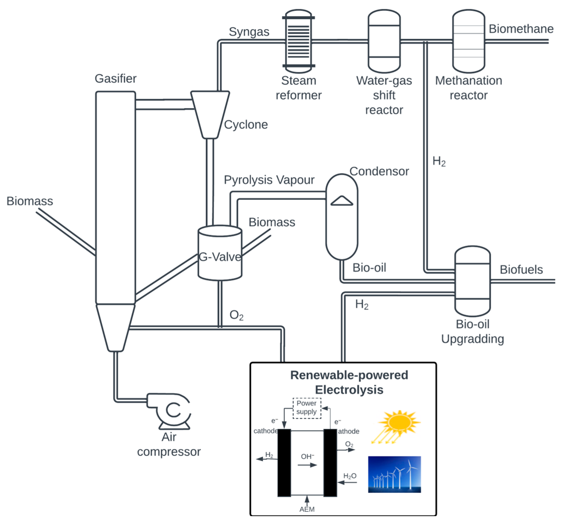
2. System Description

The proposed pilot plant is designed to explore the polygeneration of hydrogen, biomethane, and bio-oil via the integration of biomass gasification, pyrolysis, and electrolysis by utilizing renewable energy. The primary component of the pilot plant is a circulating fluidized boiler (CFB) with biomass as feedstock. The G-valve, typically used for sand and char recycling in the CFB, is retrofitted to fit the biomass pyrolysis reaction for bio-oil production. Centering on the biomass CFB, the plant is also outfitted with an electrolysis process for hydrogen generation, a cooling and distillation process for bio-oil production, and a membrane reactor system for biomethane production.
The schematic diagram of the facility is presented in Figure 1. During operation, ambient air is preheated to approximately 600 °C before being fed into the CFB, where the air transports and heats the feeding biomass to enable the gasification process to occur downstream.
The syngas generated from biomass gasification is then separated from the solids (uncombusted biomass, char, and sand) in the cyclone. The solids, which still carry heat, are directed to the G-Valve (pyrolyzer), where the sensible heat of the solids is used to support the endothermic pyrolysis reaction and to generate pyrolysis vapor. After the cooling process within a condenser, the pyrolysis vapor becomes liquid bio-oil, which will be further upgraded to biogasoline or biodiesel within the hydrotreatment reactors in the presence of hydrogen. Meanwhile, the syngas, after the cyclone, will go through a reformer and a two-stage water–gas shift reactor to enhance hydrogen generation. Then, the existing carbon monoxide and dioxide in the syngas, together with the generated hydrogen, will be sent to the methanation reactor for biomethane generation. The production of hydrogen through electrolysis, powered by renewable energy, is proposed to support the bio-oil hydrotreatment process and enhance biofuel production by facilitating the generation of biomethane. Furthermore, the oxygen from electrolysis is used to partially replace the air necessary for gasification, thereby improving the purity of syngas concentration.

3. Process Modeling

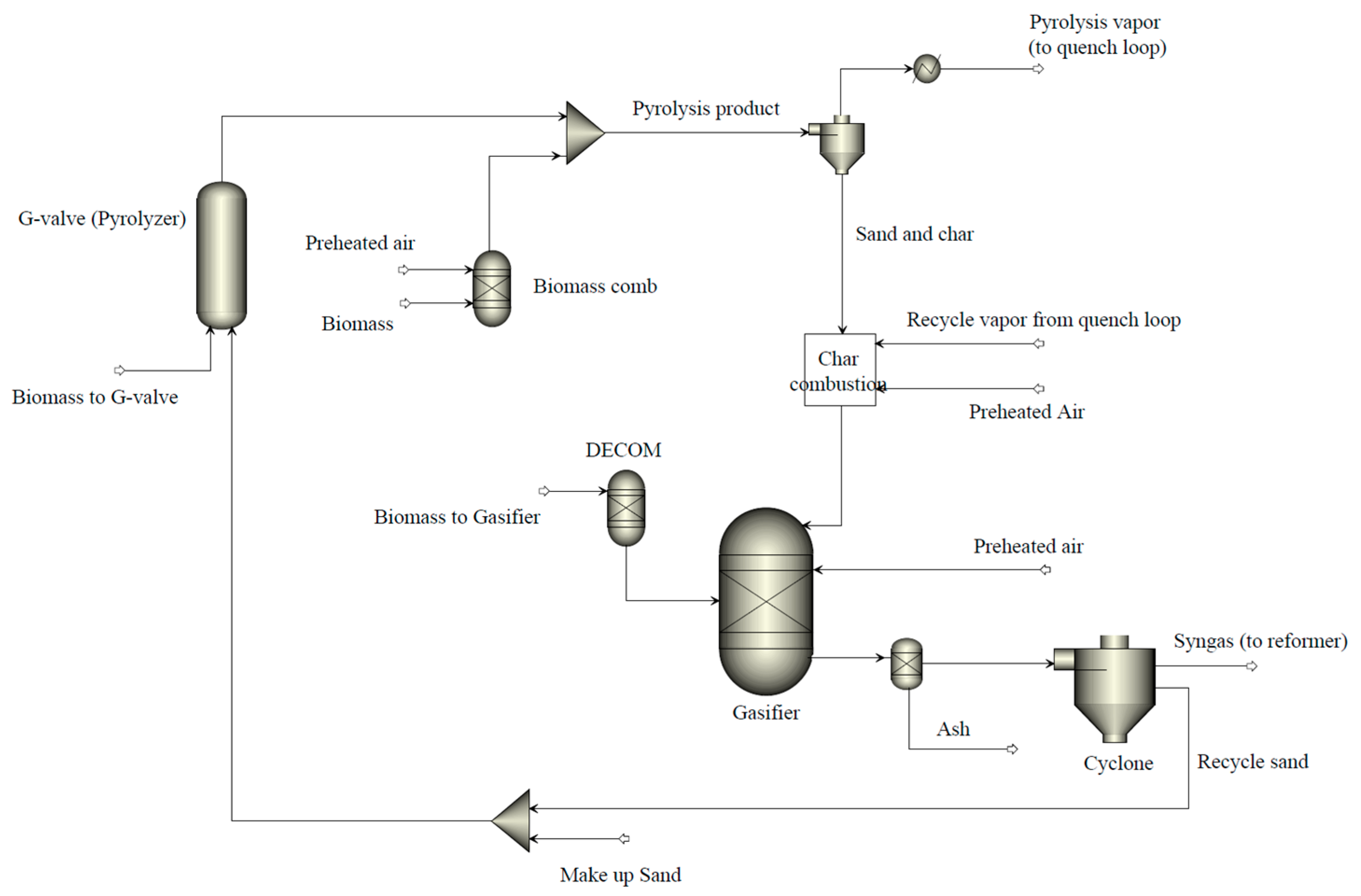
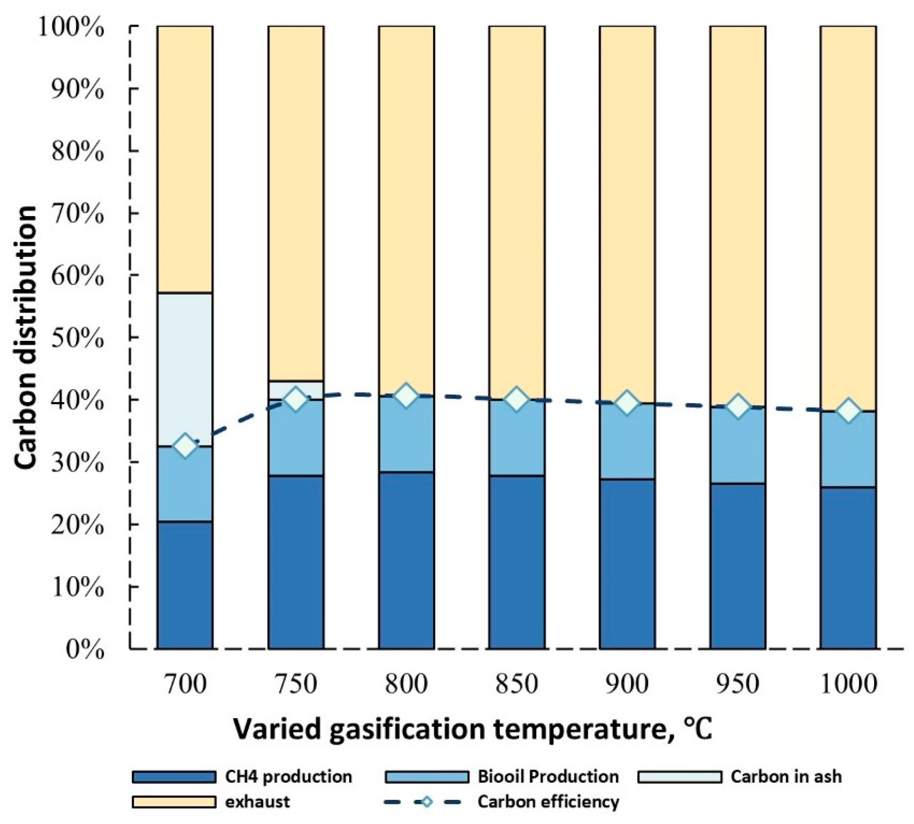
3.1. Biomass Pyrolysis Integrated with Gasification

The process model for the entire biofuel production pilot plant was established in Aspen Plus to evaluate the system performance. Figure 2 illustrates the flowsheet for incorporating the pyrolysis process into the biomass CFB gasifier in Aspen Plus. The gasification was simulated using two blocks, namely the DECOM block (RYield reactor) and the Gasifier block (Gibbs Reactor). Biomass is first converted into conventional components (C, H2, O2, N2, S, and ash) in the DECOM block, in which the product yield is calculated by an external Fortran code based on mass balance. The Gasifier block mixes the products from the DECOM block with air and simulates the gasification process by computing the thermodynamic chemical equilibrium state given by the operating parameters.
A RYield reactor (Pyrolyzer block in Figure 2) is also used to conduct the pyrolysis process in the G-Valve. It is worth noting that pyrolysis products vary from different feedstocks, operating parameters, and reactor designs; experimental investigation is required to analyze the actual pyrolysis products in real applications. In this study, the bio-oil yield was taken from the experimental data provided by Lisa et al. [35] with the pyrolysis temperature fixed at 480 °C, as shown in Table 1. To express the organics as library components for the flowsheet simulation, a set of model components, used to mix the mock bio-oil, is taken from Happs et al. [36]. More details about the simulation of fast pyrolysis with the RYield block in Aspen Plus can be found in the Aspen example document [37]. Char and ash generated from pyrolysis, along with recycled sand, are then directed into the Char Combustor block, where the solid char will be combusted. If needed, additional air will also be injected into the Biomass Comb block to supply heat for the pyrolysis. Part of the preheated air is also injected into the gasifier to support the endothermic gasification reaction. The normalized feedstock ultimate analysis is also given in Table 1, data taken from Ref. [37].

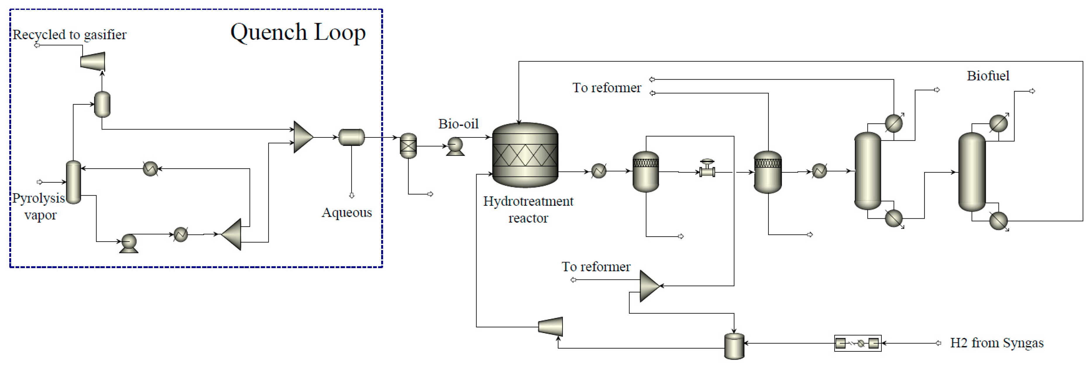
3.2. Bio-Oil Production and Upgrading with Onsite Hydrogen Generation

The pyrolysis vapor generated from the G-valve (Pyrolyzer) needs to be condensed to form bio-oil. To achieve this, a quench loop, depicted in Figure 3, is implemented to facilitate the condensation of the pyrolysis vapor into a liquid phase. Part of the pyrolysis vapor after the quench loop is sent back to the Char Combustion block (shown in Figure 2) to support the heat for gasification.
After the quench loop, bio-oil is separated with the aqueous phases from the pyrolysis product. To enhance the stability and heating value of the bio-oil, a hydrotreatment process is employed after the quench loop. Hydrotreating is a complicated process in the oil refinery process. Pyrolysis oil derived from biomass usually contains higher oxygen content compared to crude oil, which results in higher energy and hydrogen consumption [38]. In this work, the hydrotreatment parameters and reactions involved in the simulation of the pyrolysis hydrotreating process are primarily taken from the report published by the U.S. National Energy Technology Laboratory [39]. However, the outcomes can differ in actual applications due to the varying compositions of bio-oil and the operating conditions of the reactor. The hydrotreatment reactions and operating parameters employed in the Hydrotreatment Reactor block are enumerated in Table 2. The product resulting from the hydrotreatment process is directed to the distillation column, where biofuel is separated and produced. It is worth noting that the hydrogen required for bio-oil upgrading is from the gasification and renewable-powered electrolyzer process, which enables onsite self-sufficient hydrogen generation.

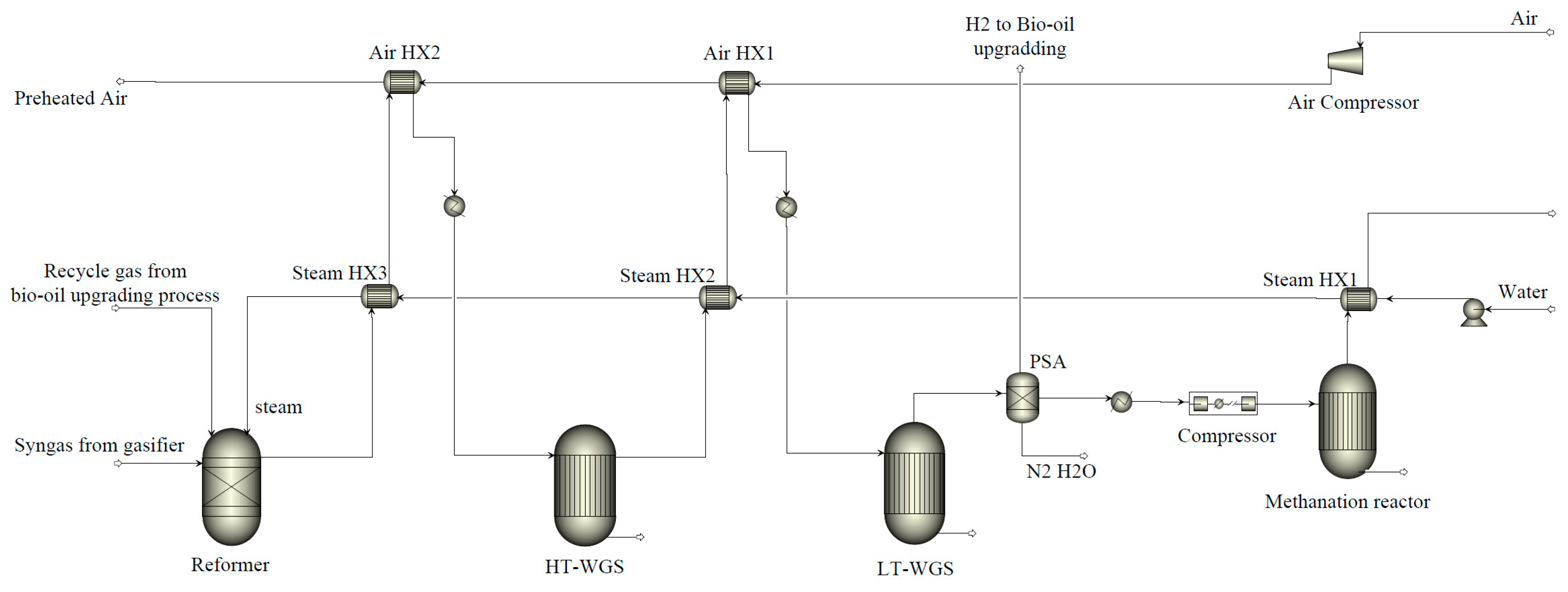
3.3. BioMethane Generation with Renewables Integration

As presented in Figure 4, to enhance the biofuel production of the pilot plant, syngas produced from the gasification process is mixed with the recycled gas from the bio-oil upgrading process and directed into the steam reformer to increase hydrogen production. To further increase hydrogen generation, a two-stage water–gas shift reactor (high-temperature water–gas shift reactor, HT-WGS, and low-temperature water–gas shift reactor, LT-WGS) is incorporated after the reformer. Subsequently, in the pressure swing adsorption (PSA) process, a portion of the hydrogen is diverted to the bio-oil upgrading process. At the same time, the remaining gas (primarily composed of H2, CO, and CO2) is compressed and channeled to the methanation reactor to produce biomethane, aiming for enhanced biofuel production and carbon capture and utilization. Additionally, air preheating and high-temperature steam generation are also implemented into the process to improve the thermal efficiency of the entire pilot plant.
Table 3 presents a summary of the operating conditions for the steam reformer, high-temperature water–gas shift reactor, low-temperature water–gas shift reactor, and methanation reactor. Note that the simulation of components in the biomethane generation process is primarily based on chemical equilibrium calculations, examining the component performance from a systematic perspective. A detailed design and simulation of those components may require the employment of kinetic models and dynamic simulations, which is beyond the scope of this study.

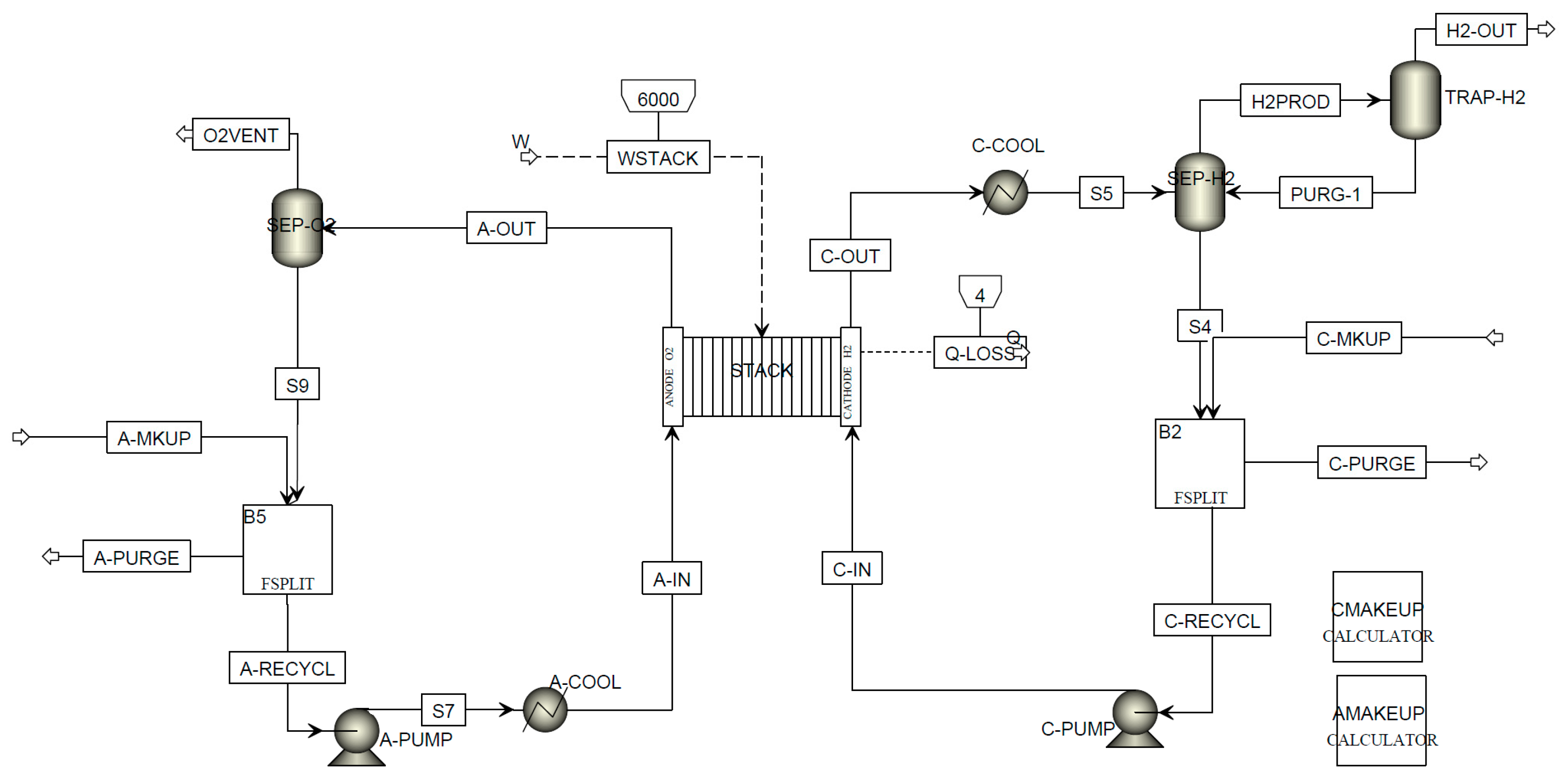
3.4. Polymer Electrolyte Membrane Electrolysis

A polymer electrolyte membrane (PEM) electrolyzer stack is employed in this work for the renewable-powered hydrogen production process. An Aspen custom modeler (ACM) model (based on the work published by Colbertaldo et al. [40] and further expanded by Botsis [41]), shown in Figure 5, is integrated with the process model of the polygeneration system. Detailed simulation and validation work for the PEM electrolyzer stack can be found in the Aspen Plus example document. It is noteworthy that this is a steady-state 0-D model, which is enough to perform system studies for this work. However, it may not be able to capture the dynamic behaviors of the electrolyzer system, which is beyond the scope of this work.
The complete process flowsheet for the entire polygeneration system model implemented in Aspen Plus is provided in Figure A1 in the Appendix A.

4. Modeling Results

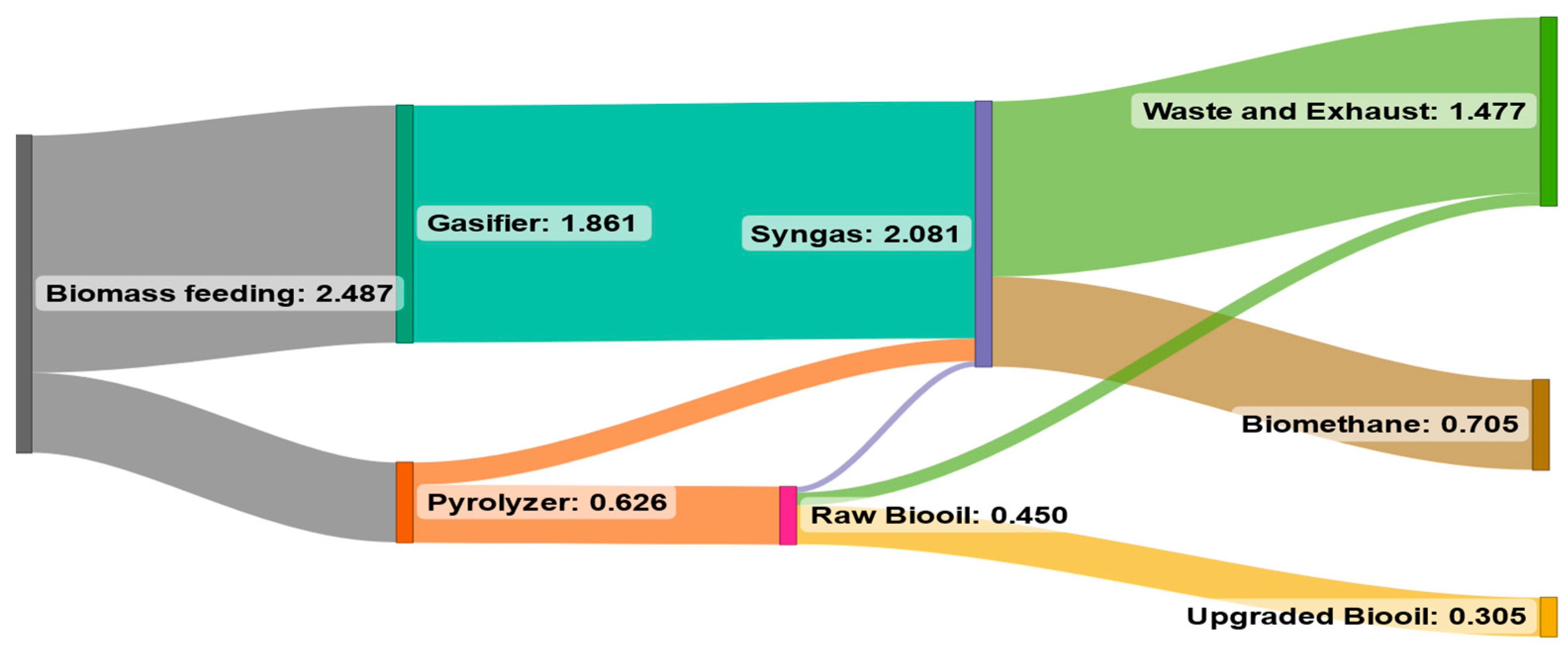
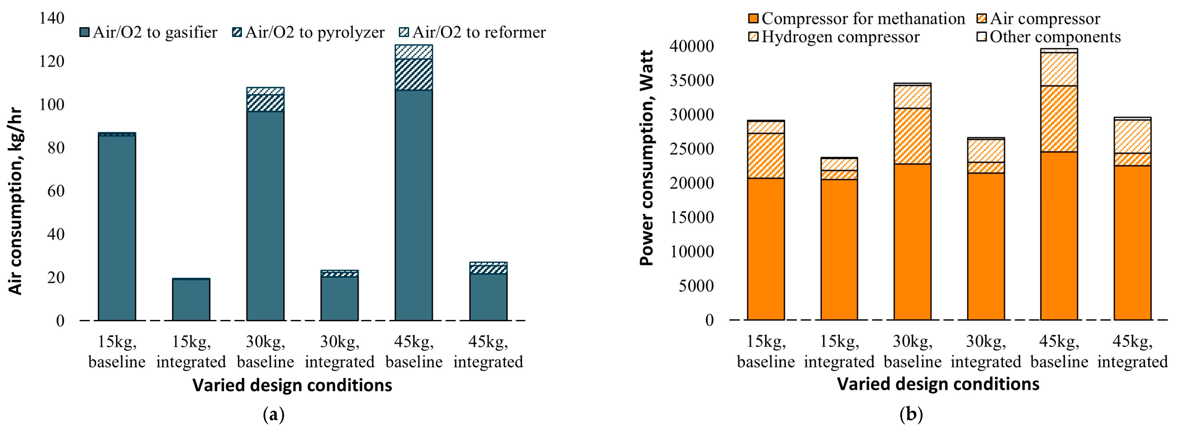
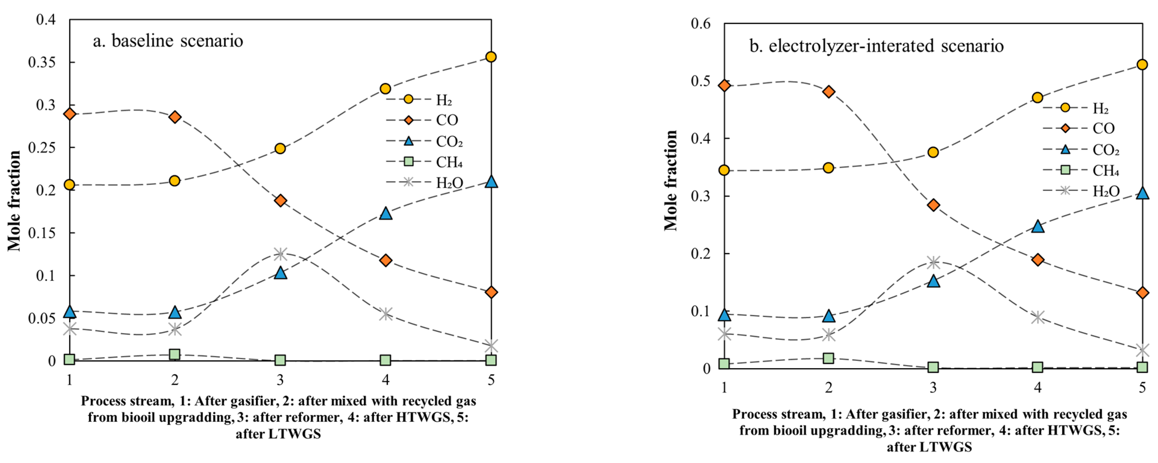
4.1. Baseline Scenario

The goal of the process modeling is to determine the optimal parameters for the plant design to improve fuel production and profitability. In this baseline scenario, the electrolyzers are not integrated with the polygeneration system, and the mass flowrates of biomass feeding into the gasifier and pyrolyzer (G-Valve) are fixed at 45 kg/h and 15 kg/h, respectively, based on the capacity of the pilot plant that is under construction at Malardalen University, Sweden.
As aforementioned, the pyrolysis and gasification processes are coupled in the polygeneration plant by taking the heat from the recycling sand to support the endothermic pyrolysis process. The uncombusted solid left from the pyrolysis is then recycled back to the gasifier to participate in the gasification process. Therefore, the operating conditions of the gasifier have a major impact on the downstream processes, such as bio-oil production and hydrogen and biomethane generation. A sensitivity analysis is then performed in this work to investigate the impacts of the operating temperature of the gasifier on the hydrogen and methane production of the proposed system. Figure 6 shows the methane production (after the methanation reactor) and hydrogen yield (after the LT-WGS reactor) when the gasification temperature varies from 700 to 1000 °C. As illustrated in Figure 6, CH4 and H2 production increases when the gasification temperature rises from 700 to 800 °C, after which the CH4 and H2 yields start to drop if the gasification temperature is further increased from 800 to 1000 °C. While gasification benefits from the higher temperature, a larger portion of air is required to support the higher operating temperature through combustion, thus resulting in reduced CO, H2, and CH4 in the syngas composition, and eventually causing a drop in H2 and CH4 production after the WGS reactor and methanation reactor.
Air and power consumption of the polygeneration system under varied operating gasification temperatures are summarized in Figure 7. As we discussed before, more air is injected into the gasifier to maintain a higher gasification temperature, which contributes to the increase in air consumption. As also shown in Figure 7a, in the case of gasification temperatures lower than 800 °C, the heat carried by the recycled sand is not enough to support the endothermic reaction; therefore, part of the air is feeding into the pyrolyzer to support the pyrolysis process. The same happens in the steam reformer reactor; part of the air is injected into the reformer to supply the heat (so-called auto-thermal reforming) when the gasification temperature is lower than 80 °C. Figure 7b demonstrates the power consumption of the polygeneration plant under different operating conditions. As shown in Figure 7b, more than half of the power consumption comes from gas compression for the methanation. The methanation reactor operates at high pressures above 30 bars (as shown in Table 3), which consumes a large amount of power to pressurize the syngas before feeding into the methanation reactor. The second largest power consumption in the system is from the hydrogen compressor, as shown in Figure 7b. A hydrogen compressor is employed to compress the hydrogen (generated from the gasification, reforming, and water–gas shifting process) to the operating pressure (40 bar) of the bio-oil hydrotreatment reactor, therefore resulting in a large proportion of power consumption.
Heat requirements and the heat produced in the polygeneration plant are described in Figure 8. The heat demand comes mainly from the bio-oil upgrading processes, such as the hydrotreatment process, water separation, and distillation process, which are about 2.8 kW. The operating conditions of the gasifier hardly affect the bio-oil production process, thus resulting in the nearly constant heat requirement with varied gasification temperatures, as shown in Figure 8a. Figure 8b shows the changes in heat production in the polygeneration plant; as more combustion is required to support the higher operating gasifier operating temperature, more heat is released from the system, approximately 9–10 kW, which provides an opportunity for use as district heating.
Figure 9 shows the carbon distribution and carbon efficiency of the polygeneration system under varied gasification temperatures. Carbon efficiency represents the proportion of carbon that has been converted into biofuels from the feedstock. As shown in Figure 9, approximately 40% of the carbon from the biomass could be captured in biomethane and bio-oil. The optimal gasification temperature in terms of the highest carbon efficiency (approximately 40%) is 800 °C. It is also worth noting that a large proportion of carbon is left in the ash when the operating temperature of the gasifier is lower than 750 °C, which is not favorable.
Figure 10 illustrates the carbon flows in the polygeneration system in the case of the 800 °C gasification temperature. More than half of the carbon is still released into the atmosphere through waste and exhaust in this case.

4.2. Electrolyzers-Integrated Scenario

In this scenario, a PEM electrolyzer stack is integrated into the polygeneration plant to provide extra hydrogen for the fuel generation process. The optimal gasification temperature determined in the baseline simulation (800 °C) is fixed in this case. Since the capacity of the pyrolyzer (G-Valve) could be relatively easy to scale up, a sensitivity analysis of the pyrolyzer capacity (varied biomass feeding mass flowrates from 15 kg/h to 45 kg/h) is performed in this work with and without the integration of the electrolyzers. The size of the electrolyzer stack is varied under different conditions to maximize the fuel production of the entire system.
Figure 11 shows the air/oxygen consumption of the entire system with different pyrolyzer capacities under the baseline scenario and electrolyzer-integrated scenario. Generally, increasing the pyrolyzer capacity results in the increased demand for air/oxygen in the polygeneration system because more air/oxygen is required to burn the combusted char left from the pyrolysis process. The oxygen generated from the electrolyzer could be used to replace the air in the system. As shown in Figure 11a, the mass flow rate of the required oxygen (electrolyzers integrated scenario) is much lower than that of the required air. This also helps to reduce the power consumption caused by air compression, as shown in Figure 11b. Thanks to the oxygen generated from the electrolyzers, the composition of the effective gas species in the syngas increases significantly without the diluting effects from the nitrogen, as illustrated in Figure 12.
Figure 13 shows the heat released from the system with varied pyrolyzer capacities for different baseline and electrolyzer-integrated scenarios. As shown in Figure 13a, the heat demand of the system increases linearly with the increase in pyrolyzer capacity. However, the heat released from the polygeneration system improves exponentially in the electrolyzers-integrated scenario (shown in Figure 13b) because of the large amount of heat generated from the methanation process and water electrolysis process, which indicates that there is an excellent opportunity for such systems to integrate with the district heating network.
Figure 14 presents the carbon distribution in the final products of the system in the baseline and electrolyzer-integrated scenarios. As shown in Figure 14, the carbon efficiency of the entire system benefits from the increase in capacity of the pyrolyzer in the baseline scenario, in which the highest carbon efficiency is approximately 45%. When integrated with the renewable-powered electrolyzers, hydrogen generated from the renewable-powered electrolyzers could capture most of the carbon in the gasification process through methanation, thus improving the carbon efficiency of the polygeneration system dramatically. As shown in Figure 14, the carbon efficiency of the system reaches approximately 90% when integrated with the electrolyzers, which demonstrates a significant improvement in fuel production and emissions reduction.
Figure 15 illustrates the carbon flows in the system when operating the gasifier at 800 °C with 45 kg/h of biomass feeding into the pyrolyzer. When integrated with renewable-powered electrolysis, the biomethane yield increases significantly along with the obvious reduction in carbon emissions.
Table 4 summarizes the fuel productions and carbon efficiencies of the polygeneration system under baseline and electrolyzer-integrated scenarios.

5. Economic Analysis

The system capacity is scaled up to the size of an existing CHP boiler in Västerås (Sweden), which has a capacity of 170 MW based on biomass LHV. Accordingly, the capacity of the pyrolyzer (G-valve) is set to be one-third of the boiler, that is 57 MW based on biomass LHV. The process model developed above is employed to simulate the scaled-up polygeneration system, delivering data for economic analysis.
A detailed economic analysis has been carried out to examine the profitability of the proposed polygeneration system by using the method from Ref. [39]. The base year selected to conduct economic analysis is 2022. The total direct cost (TDC) is first evaluated by calculating the equipment cost, balance of plant (BOP) cost, and installation cost. The capacity scaling factor and the base cost shown in Table 5 are introduced to estimate the equipment costs for each piece of equipment in the proposed system [23]. The equipment cost for each piece of equipment in the proposed system is estimated by using Equation (1):
C o s t e q u i p = C o s t b a s e C a p a c i t y e q u i p C a p a c i t y b a s e s c a l e _ f a c t o r
where Costbase is associated with the equipment cost at a base capacity, Capacitybase. The Capacityequip is the capacity of the equipment in the proposed system. A capacity scaling factor (normally within the range of 0.6–0.8) is applied to estimate the equipment cost (Costequip) in the proposed system. The Chemical Engineering Plant Cost Index (CEPCI) is implemented to estimate the cost at a specific year to take inflation into account [23], by using Equation (2):
C o s t y e a r   A = C o s t y e a r   B C E P C I y e a r   A C E P C I y e a r   B
The Installation cost and BOP cost for each main piece of equipment is estimated by applying installation factors and BOP factors to each piece of equipment. The sum of the equipment costs of main components, BOP cost, and installation/construction costs are defined as the total direct cost (TDC).
In this study, indirect cost is estimated as a fraction of the TDC. The sum of direct and indirect costs is defined as the fixed capital investment (FCI). Working capital, retrofitting cost, and operation and maintenance (O&M) costs are estimated based on FCI. The total capital investment (TCI) is then calculated based on all the costs mentioned above. The prices of crude bio-oil and upgraded bio-oil are calculated by adjusting the price on the same energy content basis as crude oil/gasoline. The assumptions and some critical inputs employed in the economic analysis are summarized in Table 6. Biomethane price and upgraded bio-oil price are evaluated from natural gas price and gasoline price, respectively, on an LHV basis.
Three economic performance indicators (net present value (NPV), payback period (PBP), and internal rate of return (IRR) are investigated as well in this study. The basic formulas to calculate NPV, PBP, and IRR are shown below:
N P V = t = 0 n C F t ( 1 + r ) t    
P B P = T C I i n i t i a l N A P
t = 0 n C F t ( 1 + I R R ) t = 0
where CFt is the cash flow at time t, r is the discount rate, n denotes a project lifetime of 20 years, TCIinitial is the initial capital investment, and NAP denotes the net annual profit.
Figure 16 shows the trend in the NPV of the polygeneration system during the project life. At the end of the project, the net present value can reach approximately 96 million EURs, with an IRR of 17.5%. It is also shown in Figure 16 that the proposed polygeneration system provides a payback period of about 9 years, proving the economic feasibility of such systems. This is mainly due to the utilization of existing CHP infrastructure, which saves a proportion of the initial investment. It is also worth noting that the natural gas price increased significantly in 2022, benefiting the economic performance of the biomethane production system.
For the electrolyzer-integrated scenario, even though the technology analysis shows that it can improve carbon efficiency and increase biomethane production, the system is not economically viable based on the economic analysis. More specifically, it requires a 454 MW electrolyzer plant to achieve a 90% carbon efficiency, which results in an investment of 1816 million EURs for the electrolyzer system for a 20-year project (considering that the current lifetime of the electrolyzer is approximately 5 years). The large cost that comes from the electrolyzer system makes the electrolyzer-integrated scenarios economically unfavorable.
A set of key input variables including biofuel selling cost, biomass cost, loan interest rate, TCI, and operating hours for the plant are selected in the sensitivity analysis with values changed by a factor of ±25% [53]. The results of sensitivity analysis on the effects of important parameters on net present value are illustrated in Figure 17. The sensitivity analysis results show that the biofuel selling price has the most significant impact on the profitability of the system. Similarly, operating hours and biomass prices also have an obvious influence on the economic performance of such systems, while the loan interest has a lesser impact on the profitability of the polygeneration system. The sensitivity analysis results also imply the importance of uncertainty analysis in future work.

6. Discussion

Retrofitting existing CHP plants for biofuel production through the integration of biomass gasification and pyrolysis technologies is investigated in this study. For the standalone polygeneration system (without the integration of renewable-powered electrolysis), the overall carbon efficiency (from biomass to fuel) of this system was found to be approximately 33–40%. This efficiency is higher than the 30% reported by the GoBiGas project [54], the world’s first commercial biomethane production plant using gasification in Sweden. The reasons for the higher efficiency observed in our study include the simulation of gasification, reforming, and methanation processes primarily under equilibrium conditions, implying longer residence times for maximum conversion, resulting in greater carbon efficiency. Additionally, the integration of fast pyrolysis in the polygeneration process contributes to this increased efficiency, as fast pyrolysis typically achieves higher carbon efficiency (approximately 44%, as noted in Dutta et al. [39]).
Introducing renewable hydrogen into the polygeneration process significantly improves the carbon efficiency in biofuel production, which is also demonstrated by other studies [55,56,57]. Due to the high investment associated with the electrolyzer system and the short lifespan of the electrolyzer, the economic analysis shows that this integration is not favorable. However, the demand for carbon-neutral fuel is anticipated to rise in the foreseeable future [58]. Additionally, the price of electrolyzer systems is anticipated to decrease significantly, due primarily to the development of technology and the increasing size of the market [59]. Those advantages could improve the profitability of such integrated systems and may require reevaluations in the future. It is also noteworthy that the economic analysis in this work relies primarily on data sourced from the literature. Conducting optimization under uncertainties (using sampling methods) [60,61] could provide deeper insights into the effects of cost fluctuations on the profitability of these systems.
It is worth noting that implementing gasification and pyrolysis technologies on a large commercial scale presents several technical challenges. These include the formation of tar, the need for thorough syngas cleaning and upgrading, and the handling of corrosive gases, as well as the hydrotreating and hydrocracking of bio-oil. For example, tar formation poses a significant challenge for the biomass gasification process. Fortunately, very small amounts of tar have been formed in our previous experiments, mainly due to the massive turbulence providing good mixing [20]. But it also requires further experimental investigations in the future to address these critical challenges.
Currently, operators of CHP plants, such as Mälarenergi AB in Sweden, are exploring energy storage solutions like battery storage and hot water storage to mitigate climate change challenges [62,63]. These approaches are expected to further reduce operational hours for auxiliary boilers typically used during peak loads. Adapting existing CHP facilities for biofuel production could not only generate additional revenue for the CHP industry but also enhance resource efficiency and contribute to a sustainable economy. This study, along with our ongoing efforts to establish a pilot plant demonstrating the proposed concept, is poised to enhance the flexibility of the CHP industry in Sweden and globally, aiding in addressing the challenges posed by the energy transition.

7. Conclusions

A polygeneration system of retrofitting existing biomass CHP plants for biofuel production was proposed and analyzed in this work. The process modeling of the polygeneration system, which integrates biomass gasification, pyrolysis, and water electrolysis processes to generate biofuels (bio-oil and biomethane), is performed in Aspen Plus. Sensitivity analysis of the key design parameters, such as gasification temperature and pyrolyzer capacity, was conducted to investigate the impacts on system performance. In addition, two scenarios with and without the integration of renewable-powered electrolyzers were simulated to explore the potential opportunities for renewable energy storage and fuel production.
The retrofitting of existing CHP plants for biofuel production provides good opportunities for sustainable fuel generation and surplus renewable energy storage. By integrating gasification and pyrolysis, the uncombusted char left from pyrolysis could be used to support the endothermic gasification process, and the hydrogen generated from gasification could be used to upgrade the bio-oil through hydrotreatment, thus improving the fuel production and profitability of such systems. The carbon efficiency of the entire system could reach up to 40% without the integration of renewable energy and electrolysis. When integrated with renewable energy, the polygeneration system could benefit from the oxygen and hydrogen produced by renewable-powered electrolysis, which increases biomethane production significantly and provides the system the potential to reach high carbon efficiency above 90%.
Economic analysis shows that the baseline scenario system (without the integration of electrolysis) could achieve a net present value of 96 million EURs with a 20-year project lifetime, which provides a payback period of approximately 9 years, demonstrating the economic feasibility of retrofitting existing CHP plants for biofuel production. Even though the technology analysis shows that integrating the electrolysis process can improve carbon efficiency and increase biomethane production, the integrated system is not economically viable, mainly due to the high costs associated with the electrolyzer system and the relatively short lifetime of the electrolyzer. However, with the development of electrolysis technologies and the increase in the price of carbon-neutral fuels, such systems may become more economically feasible in the future.

Author Contributions

Conceptualization, investigation, writing—original draft preparation, H.C.; writing—review and editing, E.D.; writing—review and editing, and funding acquisition, K.K. All authors have read and agreed to the published version of the manuscript.

Funding

This work was carried out under the IFAISTOS project (Intelligent electroFuel production for An Integrated STOrage System), which is funded under the framework of the joint programming initiative ERA-Net Smart Energy Systems. The initiative has received funding from the European Union’s Horizon 2020 research and innovation programme under grant agreements no. 646039 and no. 755970.

Data Availability Statement

Data are contained within the article.

Conflicts of Interest

The authors declare no conflicts of interest.

Appendix A

Figure A1. The entire process flowsheet of the process model of the polygeneration system in Aspen Plus.
Energies 17 00522 g0a1

References

  1. IEA. Global Energy and Climate Model; IEA: Paris, France, 2022. Available online: https://www.iea.org/reports/global-energy-and-climate-model (accessed on 27 December 2023).
  2. Fragkos, P.; van Soest, H.L.; Schaeffer, R.; Reedman, L.; Köberle, A.C.; Macaluso, N.; Evangelopoulou, S.; De Vita, A.; Sha, F.; Qimin, C.; et al. Energy system transitions and low-carbon pathways in Australia, Brazil, Canada, China, EU-28, India, Indonesia, Japan, Republic of Korea, Russia and the United States. Energy 2020, 216, 119385. [Google Scholar] [CrossRef]
  3. Scarlat, N.; Dallemand, J.; Taylor, N.; Banja, M. Brief on Biomass for Energy in the European Union; Sanchez Lopez, J., Avraamides, M., Eds.; Publications Office of the European Union: Luxembourg, 2019; ISBN 978-92-79-77235-1. [Google Scholar] [CrossRef]
  4. IEA. Technology Roadmap—Biofuels for Transport; License: CC BY 4.0; IEA: Paris, France, 2011; Available online: https://www.iea.org/reports/technology-roadmap-biofuels-for-transport (accessed on 27 December 2023).
  5. Van Dyk, S.; Su, J.; Mcmillan, J.D.; Saddler, J. Potential synergies of drop-in biofuel production with further co-processing at oil refineries. Biofuels Bioprod. Biorefin. 2019, 13, 760–775. [Google Scholar] [CrossRef]
  6. Kohl, T.; Laukkanen, T.P.; Järvinen, M.P. Integration of biomass fast pyrolysis and precedent feedstock steam drying with a municipal combined heat and power plant. Biomass Bioenergy 2014, 71, 413–430. [Google Scholar] [CrossRef]
  7. Karvonen, J.; Kunttu, J.; Suominen, T.; Kangas, J.; Leskinen, P.; Judl, J. Integrating fast pyrolysis reactor with combined heat and power plant improves environmental and energy efficiency in bio-oil production. J. Clean. Prod. 2018, 183, 143–152. [Google Scholar] [CrossRef]
  8. Kohl, T.; Teles, M.; Melin, K.; Laukkanen, T.; Järvinen, M.; Park, S.W.; Guidici, R. Exergoeconomic assessment of CHP-integrated biomass upgrading. Appl. Energy 2015, 156, 290–305. [Google Scholar] [CrossRef]
  9. Onarheim, K.; Lehto, J.; Solantausta, Y. Technoeconomic Assessment of a Fast Pyrolysis Bio-oil Production Process Integrated to a Fluidized Bed Boiler. Energy Fuels 2015, 29, 5885–5893. [Google Scholar] [CrossRef]
  10. Zetterholm, J.; Wetterlund, E.; Pettersson, K.; Lundgren, J. Evaluation of value chain configurations for fast pyrolysis of lignocellulosic biomass—Integration, feedstock, and product choice. Energy 2018, 144, 564–575. [Google Scholar] [CrossRef]
  11. Daraei, M.; Campana, P.-E.; Avelin, A.; Jurasz, J.; Thorin, E. Impacts of integrating pyrolysis with existing CHP plants and onsite renewable-based hydrogen supply on the system flexibility. Energy Convers. Manag. 2021, 243, 114407. [Google Scholar] [CrossRef]
  12. Björnsson, L.; Pettersson, M.; Börjesson, P.; Ottosson, P.; Gustavsson, C. Integrating bio-oil production from wood fuels to an existing heat and power plant—Evaluation of energy and greenhouse gas performance in a Swedish case study. Sustain. Energy Technol. Assess. 2021, 48, 101648. [Google Scholar] [CrossRef]
  13. Pettersson, M.; Olofsson, J.; Börjesson, P.; Björnsson, L. Reductions in greenhouse gas emissions through innovative co-production of bio-oil in combined heat and power plants. Appl. Energy 2022, 324, 119637. [Google Scholar] [CrossRef]
  14. Yang, Y.; Wang, J.; Chong, K.; Bridgwater, A.V. A techno-economic analysis of energy recovery from organic fraction of municipal solid waste (MSW) by an integrated intermediate pyrolysis and combined heat and power (CHP) plant. Energy Convers. Manag. 2018, 174, 406–416. [Google Scholar] [CrossRef]
  15. Mostafazadeh, A.K.; Solomatnikova, O.; Drogui, P.; Tyagi, R.D. A review of recent research and developments in fast pyrolysis and bio-oil upgrading. Biomass Convers. Biorefin. 2018, 8, 739–773. [Google Scholar] [CrossRef]
  16. Stefanidis, S.D.; Kalogiannis, K.G.; Lappas, A.A. Co-processing bio-oil in the refinery for drop-in biofuels via fluid catalytic cracking. Wiley Interdiscip. Rev. Energy Environ. 2018, 7, e281. [Google Scholar] [CrossRef]
  17. Raud, M.; Kikas, T.; Sippula, O.; Shurpali, N. Potentials and challenges in lignocellulosic biofuel production technology. Renew. Sustain. Energy Rev. 2019, 111, 44–56. [Google Scholar] [CrossRef]
  18. Piazzi, S.; Menin, L.; Antolini, D.; Patuzzi, F.; Baratieri, M. Potential to retrofit existing small-scale gasifiers through steam gasification of biomass residues for hydrogen and biofuels production. Int. J. Hydrogen Energy 2021, 46, 8972–8985. [Google Scholar] [CrossRef]
  19. Gustavsson, C.; Hulteberg, C. Co-production of gasification based biofuels in existing combined heat and power plants—Analysis of production capacity and integration potential. Energy 2016, 111, 830–840. [Google Scholar] [CrossRef]
  20. Naqvi, M.; Dahlquist, E.; Yan, J. Complementing existing CHP plants using biomass for production of hydrogen and burning the residual gas in a CHP boiler. Biofuels 2017, 8, 675–683. [Google Scholar] [CrossRef]
  21. Thunman, H.; Gustavsson, C.; Larsson, A.; Gunnarsson, I.; Tengberg, F. Economic assessment of advanced biofuel production via gasification using cost data from the GoBiGas plant. Energy Sci. Eng. 2019, 7, 217–229. [Google Scholar] [CrossRef]
  22. Holmgren, K.M.; Berntsson, T.S.; Andersson, E.; Rydberg, T. Comparison of integration options for gasification-based biofuel production systems—Economic and greenhouse gas emission implications. Energy 2016, 111, 272–294. [Google Scholar] [CrossRef]
  23. Salman, C.A.; Naqvi, M.; Thorin, E.; Yan, J. Gasification process integration with existing combined heat and power plants for polygeneration of dimethyl ether or methanol: A detailed profitability analysis. Appl. Energy 2018, 226, 116–128. [Google Scholar] [CrossRef]
  24. Brynda, J.; Skoblia, S.; Pohořelý, M.; Beňo, Z.; Soukup, K.; Jeremiáš, M.; Moško, J.; Zach, B.; Trakal, L.; Šyc, M.; et al. Wood chips gasification in a fixed-bed multi-stage gasifier for decentralized high-efficiency CHP and biochar production: Long-term commercial operation. Fuel 2020, 281, 118637. [Google Scholar] [CrossRef]
  25. Butera, G.; Jensen, S.H.; Ahrenfeldt, J.; Clausen, L.R. Techno-economic analysis of methanol production units coupling solid oxide cells and thermochemical biomass conversion via the TwoStage gasifier. Fuel Process. Technol. 2021, 215, 106718. [Google Scholar] [CrossRef]
  26. Costa, P.; Pinto, F.; André, R.N.; Marques, P. Integration of Gasification and Solid Oxide Fuel Cells (SOFCs) for Combined Heat and Power (CHP). Processes 2021, 9, 254. [Google Scholar] [CrossRef]
  27. Herdem, M.S. Performance investigation of a non-combustion heat carrier biomass gasifier for various reforming methods of pyrolysis products. Int. J. Green Energy 2022, 19, 62–71. [Google Scholar] [CrossRef]
  28. Samadi, S.H.; Ghobadian, B.; Nosrati, M. Prediction and estimation of biomass energy from agricultural residues using air gasification technology in Iran. Renew. Energy 2020, 149, 1077–1091. [Google Scholar] [CrossRef]
  29. Ramadhani, B.; Kivevele, T.; Kihedu, J.H.; Jande, Y.A.C. Catalytic tar conversion and the prospective use of iron-based catalyst in the future development of biomass gasification: A review. Biomass Convers. Biorefin. 2020, 12, 1369–1392. [Google Scholar] [CrossRef]
  30. Situmorang, Y.A.; Zhao, Z.; Yoshida, A.; Abudula, A.; Guan, G. Small-scale biomass gasification systems for power generation (<200 kW class): A review. Renew. Sustain. Energy Rev. 2020, 117, 109486. [Google Scholar] [CrossRef]
  31. Pio, D.; Tarelho, L. Industrial gasification systems (>3 MWth) for bioenergy in Europe: Current status and future perspectives. Renew. Sustain. Energy Rev. 2021, 145, 111108. [Google Scholar] [CrossRef]
  32. Mignard, D.; Pritchard, C. On the use of electrolytic hydrogen from variable renewable energies for the enhanced conversion of biomass to fuels. Chem. Eng. Res. Des. 2008, 86, 473–487. [Google Scholar] [CrossRef]
  33. Dossow, M.; Dieterich, V.; Hanel, A.; Spliethoff, H.; Fendt, S. Improving carbon efficiency for an advanced Biomass-to-Liquid process using hydrogen and oxygen from electrolysis. Renew. Sustain. Energy Rev. 2021, 152, 111670. [Google Scholar] [CrossRef]
  34. Salman, C.A.; Thorin, E.; Yan, J. Opportunities and limitations for existing CHP plants to integrate polygeneration of drop-in biofuels with onsite hydrogen production. Energy Convers. Manag. 2020, 221, 113109. [Google Scholar] [CrossRef]
  35. Iisa, K.; French, R.J.; Orton, K.A.; Dutta, A.; Schaidle, J.A. Production of low-oxygen bio-oil via ex situ catalytic fast pyrolysis and hydrotreating. Fuel 2017, 207, 413–422. [Google Scholar] [CrossRef]
  36. Happs, R.M.; Iisa, K.; Iii, J.R.F. Quantitative 13C NMR characterization of fast pyrolysis oils. RSC Adv. 2016, 6, 102665–102670. [Google Scholar] [CrossRef]
  37. Aspen Plus. Biomass Pyrolysis Modeling—Simplified Conversion with Excel and RYield. 2021. Available online: https://knowledgecenter.aspentech.com/item/kb/kA04P000000jEgSSAU?idx=4&AT_EPReference=Aspen%20Plus&AT_EVReference=12 (accessed on 27 December 2023).
  38. Spadaro, L.; Palella, A.; Frusteri, F.; Arena, F. Valorization of crude bio-oil to sustainable energy vector for applications in cars powering and on-board reformers via catalytic hydrogenation. Int. J. Hydrogen Energy 2015, 40, 14507–14518. [Google Scholar] [CrossRef]
  39. Dutta, A.S.; Sahir, A.H.; Tan, E.; Humbird, D.; Snowden-Swan, L.J.; Meyer, P.A.; Ross, J.; Sexton, D.; Yap, R.; Lukas, J. Process Design and Economics for the Conversion of Lignocellulosic Biomass to Hydrocarbon Fuels: Thermochemical Research Pathways with in Situ and ex Situ Upgrading of Fast Pyrolysis Vapors (No. PNNL-23823); Pacific Northwest National Laboratory (PNNL): Richland, WA, USA, 2015. [Google Scholar]
  40. Colbertaldo, P.; Aláez, S.L.G.; Campanari, S. Zero-dimensional dynamic modeling of PEM electrolyzers. Energy Procedia 2017, 142, 1468–1473. [Google Scholar] [CrossRef]
  41. Botsis, V. Development of a Stationary and a Preliminary Dynamic Model for Proton Exchange Membrane (PEM) Electrolyzer; Politecnico di Milano: Milan, Italy, 2019. [Google Scholar]
  42. Liu, G.; Larson, E.D.; Williams, R.H.; Kreutz, T.G.; Guo, X. Making Fischer−Tropsch Fuels and Electricity from Coal and Biomass: Performance and Cost Analysis. Energy Fuels 2011, 25, 415–437. [Google Scholar] [CrossRef]
  43. Holmgren, K.M.; Berntsson, T.S.; Andersson, E.; Rydberg, T. Perspectives on investment cost estimates for gasification-based biofuel production systems. Chem. Eng. Trans. 2015, 45, 427–432. [Google Scholar]
  44. Heyne, S.; Harvey, S. Impact of choice of CO2 separation technology on thermo-economic performance of Bio-SNG production processes. Int. J. Energy Res. 2014, 38, 299–318. [Google Scholar] [CrossRef]
  45. Kotowicz, J.; Węcel, D.; Jurczyk, M. Analysis of component operation in power-to-gas-to-power installations. Appl. Energy 2018, 216, 45–59. [Google Scholar] [CrossRef]
  46. Turton, R.; Bailie, R.C.; Whiting, W.B.; Shaeiwitz, J.A. Analysis, Synthesis and Design of Chemical Processes; Pearson Education: London, UK, 2008. [Google Scholar]
  47. Salkuyeh, Y.K.; Adams, T.A., II. A new power, methanol, and DME polygeneration process using integrated chemical looping systems. Energy Convers. Manag. 2014, 88, 411–425. [Google Scholar] [CrossRef]
  48. Peters, M.S.; Timmerhaus, K.D.; West, R.E. Plant Design and Economics for Chemical Engineers; McGraw-Hill: New York, NY, USA, 2003; Volume 4. [Google Scholar]
  49. Swedish Energy Agency—Wood Fuel and Peat Prices; Data Taken from 2022Q3. Available online: https://pxexternal.energimyndigheten.se/pxweb/sv/ (accessed on 27 December 2023).
  50. District Heating Prices—Swedish District Heating; [Data Taken from District Heat Price at Mälarenergi, Västerås 2022]. Available online: https://www.energiforetagen.se/statistik/fjarrvarmestatistik/fjarrvarmepriser/ (accessed on 27 December 2023).
  51. Gas Prices for Household Consumers—Bi-Annual Data (from 2007 Onwards), Eurostat. data taken from 2022-S1. Available online: https://ec.europa.eu/eurostat/databrowser/view/nrg_pc_202/default/table?lang=en (accessed on 27 December 2023).
  52. Trading Economics. Sweden Gasoline Prices. Available online: https://tradingeconomics.com/sweden/gasoline-prices (accessed on 1 July 2022).
  53. Salman, C.A.; Naqvi, M.; Thorin, E.; Yan, J. Impact of retrofitting existing combined heat and power plant with polygeneration of biomethane: A comparative techno-economic analysis of integrating different gasifiers. Energy Convers. Manag. 2017, 152, 250–265. [Google Scholar] [CrossRef]
  54. Larsson, A.; Gunnarsson, I.; Tengberg, F. The GoBiGas project-demonstration of the production of biomethane from biomass via gasification. Göteb. Energi 2018, 10, 1–101. [Google Scholar]
  55. Poluzzi, A.; Guandalini, G.; Guffanti, S.; Elsido, C.; Moioli, S.; Huttenhuis, P.; Rexwinkel, G.; Martelli, E.; Groppi, G.; Romano, M.C. Flexible Power & Biomass-to-Methanol plants: Design optimization and economic viability of the electrolysis integration. Fuel 2022, 310, 122113. [Google Scholar] [CrossRef]
  56. Onarheim, K.; Hannula, I.; Solantausta, Y. Hydrogen enhanced biofuels for transport via fast pyrolysis of biomass: A conceptual assessment. Energy 2020, 199, 117337. [Google Scholar] [CrossRef]
  57. Hillestad, M.; Ostadi, M.; Serrano, G.A.; Rytter, E.; Austbø, B.; Pharoah, J.; Burheim, O. Improving carbon efficiency and profitability of the biomass to liquid process with hydrogen from renewable power. Fuel 2018, 234, 1431–1451. [Google Scholar] [CrossRef]
  58. Long, S.P. Bioenergy—The slope of enlightenment. Global Change Biology. Bioenergy 2020, 12, 462–463. [Google Scholar]
  59. International Renewable Energy Agency. Green Hydrogen Cost Reduction: Scaling Up Electrolysers to Meet the 1.5 °C Climate Goal; International Renewable Energy Agency: Abu Dhabi, United Arab Emirates, 2020. [Google Scholar]
  60. Chen, H.; Yang, C.; Deng, K.; Zhou, N.; Wu, H. Multi-objective optimization of the hybrid wind/solar/fuel cell distributed generation system using Hammersley Sequence Sampling. Int. J. Hydrogen Energy 2017, 42, 7836–7846. [Google Scholar] [CrossRef]
  61. Zhang, T.; Yang, C.; Chen, H.; Sun, L.; Deng, K. Multi-objective optimization operation of the green energy island based on Hammersley sequence sampling. Energy Convers. Manag. 2020, 204, 112316. [Google Scholar] [CrossRef]
  62. Mälarenergi, A.B. Mälarenergi Cooperates with Mine Storage for Energy Storage. Blog—The Journey to Zero. 2 February 2022. Available online: https://blogg.malarenergi.se/malarenergi-samarbetar-med-mine-storage-for-energilagring/ (accessed on 27 December 2023).
  63. Northvolt. Northvolt & Mälarenergi Partner to Deploy Battery Energy Storage for EV Charging. 26 November 2019. Available online: https://northvolt.com/articles/northvolt-malarenergi-partner/ (accessed on 27 December 2023).
Figure 1. Schematic diagram of biomass pyrolysis, gasification, and electrolysis integrated polygeneration system.
Energies 17 00522 g001
Figure 2. Process flowsheet of biomass pyrolysis integrated with gasification process in Aspen Plus.
Energies 17 00522 g002
Figure 3. Process flowsheet of bio-oil production and upgrading process in Aspen Plus.
Energies 17 00522 g003
Figure 4. Process flowsheet of hydrogen and biomethane production process in Aspen Plus.
Energies 17 00522 g004
Figure 5. ACM model for PEM electrolyzer stack in Aspen Plus.
Energies 17 00522 g005
Figure 6. CH4 and H2 production after methanation reactor and LT-WGS, respectively.
Energies 17 00522 g006
Figure 7. Air consumption (a) and power consumption (b) in the polygeneration system, baseline scenario.
Energies 17 00522 g007
Figure 8. Heat demand (a) and the heat produced in the polygeneration system (b), baseline scenario.
Energies 17 00522 g008
Figure 9. Carbon distribution in the final products and carbon efficiency of the polygeneration system, baseline scenario.
Energies 17 00522 g009
Figure 10. Carbon flows (kmol/h) in the polygeneration system with 800 °C gasification temperature, the baseline scenario.
Energies 17 00522 g010
Figure 11. Air consumption (a) and power consumption (b) in the baseline and electrolyzers-integrated scenarios.
Energies 17 00522 g011
Figure 12. Molar concentration at varied locations in the process line for the baseline (a) and electrolyzer-integrated (b) scenarios.
Energies 17 00522 g012
Figure 13. Heat demand (a) and the heat produced (b) in the baseline and electrolyzer-integrated scenarios.
Energies 17 00522 g013
Figure 14. Carbon distribution in the final products and carbon efficiency in the baseline and electrolyzer-integrated scenarios.
Energies 17 00522 g014
Figure 15. Carbon flows (kmol/h) in the polygeneration system under the electrolyzer-integrated scenario (800 ℃ gasification temperature and 45 kg/h biomass feeding into the pyrolyzer).
Energies 17 00522 g015
Figure 16. The net present value of the polygeneration system (baseline scenario) during the project life.
Energies 17 00522 g016
Figure 17. Sensitivity analysis on the change in net present value of the polygeneration system (baseline scenario).
Energies 17 00522 g017
Table 1. Ultimate analysis of the feedstock and product yield for the pyrolysis.
Ultimate Analysis of the FeedstockProduct Yield for the Pyrolysis
Carbon49.66%H20.0000
Hydrogen6.31%CO0.0582
Oxygen43.55%CO20.0603
Nitrogen0.10%CH40.0028
Sulfur0.08%C2H40.0028
Ash0.30%Acetic Acid, C2H4O20.1107
Acetone, C3H6O0.1272
LHV17.3 MJ/kgM-Cresol, C7H8O0.0398
Coniferyl Aldehyde, C10H10O30.0068
Guaiacol, C7H8O20.2680
Levoglucosan, C6H10O50.0440
Furfural, C5H4O20.0294
Water, H2O0.1480
Char0.0968
Table 2. Reactions and operating parameters in the hydrotreatment reactor.
Operating Parameters of the Hydrotreatment Reactor
Temperature400 °C
Pressure105 bar
Chemical reactions considered in the Hydrotreatment reactor
1Acetic Acid+ 2 H2 = Ethanol+ H2O
2Furfural + 3 H2 = Tetrahydrofurfuryl alcohol
3Levoglucosan + H2 + H2O = Sorbitol
4H2 + M-Cresol = Toluene + H2O
54 H2 + M-Cresol = Methylcyclohexane + H2O
6Guaiacol + 6 H2 = Cyclohexane + 2 H2O+ CH4
7Guaiacol + 3 H2 = 2 H2O+ CH4+ Benzene
8Benzene + 3 H2 = Cyclohexane
9Coniferyl Aldehyde + 2 H2 = Toluene + 2 CO+ CH4+ H2O
10Toluene + 3 H2 = Methylcyclohexane
11Coniferyl Aldehyde + 3 H2 = Ethylbenzene + CO2+ CH4+ H2O
Table 3. Specifications used for reformer, water–gas shift reactor, and methanation reactor.
Block NameSpecifications
Steam reformer (RGibbs)Pressure−0.20 bar
Temperature800 °C
HT-WGS (REquil)Pressure drop−0.35 bar
Inlet temperature340 °C
ReactionsCO + H2O = CO2 + H2
LT-WGS (REquil)Pressure drop−0.35 bar
Inlet temperature220 ℃
ReactionsCO + H2O = CO2 + H2
Methanation reactor (REquil)Pressure30 bar
Temperature360 °C
ReactionsCO + H2 = CH4 + H2O
CO2 +4 H2 = CH4 + 2H2O
CO + H2O = CO2 + H2
Table 4. Fuel productions and carbon efficiencies of the polygeneration system under baseline and electrolyzer-integrated scenarios (*).
Biomass to Pyrolyzer (kg/h)Bio-Oil Production
(kg/h)
Lower Heating Value of Biomethane (kWh/kg)Biomethane ProductionCarbon Efficiency (%)Required PEM Stack Size (kW)
Baseline scenario
154.810.111.340.6/
309.510.112.543.9/
4514.210.113.545.7/
Electrolyzers-integrated scenario
154.810.133.395.7672
309.610.137.793.8795
4514.410.142.492.9923
(*) the operating temperatures of the pyrolyzer and the gasifier are fixed at 480 °C and 800 °C, respectively, and the mass flow rate of biomass feeding into the gasifier is 45 kg/h in all cases.
Table 5. Base capital costs for main equipment in the pyrolysis system for biofuel production.
EquipmentBase
Capacity
Base Cost
(Million €)
Base YearCapacity
Scaling Factor
BOP
Cost Factor
Installation
Cost Factor
Indirect Cost
(% of TDC)
Ref.
Biomass preparation198.1 ton/h (biomass)3.520070.620.16included32[42]
Biomass dryer204,131 lb/h (biomass)0.120110.8included1.060[39]
Fast pyrolysis reactor2000 ton (biomass)
/day
6.920110.53.62.160[39]
Condensation and Separation310,342 lb/h (pyrolysis vapor)1.120130.64.80.9260[39]
Hydrotreating56,010 lb/h (crude bio-oil)4.820131.01.00.6760[39]
Oil fractionation46,446 lb/h (upgraded oil)0.520130.72.81.560[39]
Steam reformer31,000 kmol/h (syngas at exit)93.720070.9includedincludedincluded[42]
WGS reactor
(two stages)
815 MW (dried biomass LHV)8.420070.670.16includedincluded[42]
PSA5218 Lb/h0.9820130.6included1.860[39]
Compressor
(H2 and methane)
10 MW6.320070.67includedincluded32[43]
Gasifier (CFB)483 MW biomass LHV17320070.5includedincludedIncluded[42]
MEA CO2 removal0.5 kg/s CO2 removal5.220100.7includedincluded20[44]
Gas drying21 kg/h H2O removal0.07420040.67includedincluded20[44]
Electrolyzer1 MW1.020181.0includedincludedincluded[45]
Table 6. Assumptions and key inputs in economic analysis.
ParametersValueRef.
Project economic life, years20Assumed
Construction period, years3[46]
Equity, % of TCI60Assumed
Loan interest, %10[47]
Loan term, years10[23]
Discount rate, %10[23]
Retrofitting cost, % of FCI20Assumed
Working capital, % of FCI15[48]
O&M cost, % of FCI4[46]
Operating hours, h/year7884[39]
Prices (exclude tax)
Biomass price, €/MWh20[49]
Electricity, €/MWh82[50]
Natural gas price, €/MWh75[51]
Gasoline price, €/L1.37[52]
Disclaimer/Publisher’s Note: The statements, opinions and data contained in all publications are solely those of the individual author(s) and contributor(s) and not of MDPI and/or the editor(s). MDPI and/or the editor(s) disclaim responsibility for any injury to people or property resulting from any ideas, methods, instructions or products referred to in the content.

