Article

A Multi-Source Power System’s Load Frequency Control Utilizing Particle Swarm Optimization

1
School of Electrical Engineering, Yanshan University, Qinhuangdao 066004, China
2
Key Laboratory of Power Electronics for Energy Conservation and Drive Control of Hebei Province, Yanshan University, Qinhuangdao 066004, China
3
Department of Electric Power Station and Automation of Power Systems, The Institute of Energy, Peter the Great Saint-Petersburg Polytechnic University, 195251 Saint Petersburg, Russia
*
Author to whom correspondence should be addressed.
Energies 2024, 17(2), 517; https://doi.org/10.3390/en17020517
Submission received: 20 November 2023 / Revised: 24 December 2023 / Accepted: 11 January 2024 / Published: 20 January 2024
(This article belongs to the Section F: Electrical Engineering)

Abstract

:
Electrical power networks consist of numerous energy control zones connected by tie-lines, with the addition of nonconventional sources resulting in considerable variations in tie-line power and frequency. Under these circumstances, a load frequency control (LFC) loop gives constancy and security to interconnected power systems (IPSs) by supplying all consumers with high-quality power at a nominal frequency and tie-line power change. This article proposes employing a proportional–integral–derivative (PID) controller to effectively control the frequency in a one-area multi-source power network comprising thermal, solar, wind, and fuel cells and in a thermal two-area tie-line IPS. The particle swarm optimization (PSO) technique was utilized to tune the PID controller parameters, with the integral time absolute error being utilized as an objective function. The efficacy and stability of the PSO-PID controller methodology were further tested in various scenarios for proposed networks. The frequency fluctuations associated with the one-area multi-source power source and with the two-area tie-line IPS’s area 1 and area 2 frequency variations were 59.98 Hz, 59.81 Hz, and 60 Hz, respectively, and, in all other investigated scenarios, they were less than that of the traditional PID controller. The results clearly show that, in terms of frequency responses, the PSO-PID controller performs better than the conventional PID controller.

1. Introduction

With the widespread use of smart grid technology and a variety of renewable energy sources (RESs), current power systems are changing rapidly. The components of an integrated power system are loads, distribution, transmission, and generation. In a larger integrated electrical power system, a tie-line connects many geographically separated service zones. As modern power systems continue to grow in size and complexity, the challenges and difficulties that they may encounter are expected to increase [1,2]. Power production varies proportionately with load demand to ensure the stability of system performance. Rapid increases in power demand affect the stability of the entire power unit in a system or any linked system [3,4].
The energy generation in each area needs to be regulated in order to sustain a planned power exchange among different areas. In an interconnected power system (IPS), load frequency control (LFC) schemes generate and provide power consistently and reliably while maintaining acceptable frequency limitations. In an electrical power network, the load is constantly variable. The frequency of the system changes in a highly unfavorable way due to the difference between generating power and load demand, due to which oscillations occur and the equilibrium state floats; when this equilibrium is disturbed, the frequency is restored to another level. This leads to extreme instability in the electrical network and significant damage to expensive equipment. The variation in frequency can be managed by modifying the active power demands via the LFC control loop’s speed governor action. Maintaining the equilibrium of active capabilities requires control. Therefore, in order to solve this issue of unpredictable variations in load and keep the frequency at acceptable rated levels, a control system is necessary. The best control greatly depends on the controller’s precise tuning scheme design. This paper aims to optimize the controller gain parameters of a proportional–integral–derivative (PID) controller by utilizing a metaheuristic algorithm, particle swarm optimization (PSO), to effectively control the system frequency for a one-area multi-source power network and a two-area tie-line IPS [5,6]. The proposed power networks were designed in a MATLAB/Simulink 2020a environment; the proposed networks with PID controllers were tested by changing the system parameters ±50% for different cases in both networks, along with load variations in different cases for the two-area tie-line IPS. The PSO technique was utilized to tune the PID controller parameters, with an integral time absolute error (ITAE) being utilized as the objective function. The PID controller with the used algorithm successfully optimized the frequency responses and tie-line power deviations in the proposed networks. These results clearly indicate that the PSO-PID controller is superior to conventional PID controllers in terms of undershoot, overshoot, pre-shoot, and frequency responses. The outcomes of the PID controller and optimization approach that we tested and used for the proposed networks are covered in the sections below.

1.1. Literature Review

The author [7] solved the LFC problem of linked thermal power systems by optimizing the parameters of PID control utilizing the PSO technique. When contrasting the HC- and GA-tuned controllers’ performance with that of the recommended PSO-PID controller, it was clear which one performed better. In [8], for a self-sustaining nuclear power station’s LFC, the author employed the ACO algorithm using the PID controller. A trial-and-error methodology was utilized to compare the responses. In [9], the author optimized the parameters of a PID controller utilizing the ARA technique for two-area non-reheat multi-area power systems (MAPSs). In [10], a photovoltaic (PV) model and a wind farm were combined into an LFC power system. In [11], LFC approaches were utilized to adjust the frequency as well as multi-source electricity from generators powered by diesel, photovoltaics, and wind generators, which were all considered to be components of a power system with several sources. In [12], the LFC renewable power system’s ideal PID parameter values were found using a nonconventional quasi-oppositional dragonfly approach. Within LFC power networks, prolonged significant variations in tie-line power exchange and system frequency can be detrimental to appliances, cause operational instability, shorten the lifespan of linked devices, or even cause the power system to crash. An analysis was conducted on LFC in a multi-source power network using a tuned parameter-based controller with a differential evolution algorithm [13]. The gain value for the PI controller designed for one-area power network frequency management was adjusted via stochastic PSO.
The connected power network LFC, which comprised thermal and PV networks, was intended to be solved utilizing the PSO approach used via a BF-tuned PID controller [14]. The LFC of grid-connected electrical power networks, using the PSO-associated MARL technique, was put into practice [15]. In [16], the FPA technique was used to improve the PID controller parameters of linked power grids’ LFC issues. The efficiency of the proposed FPA technique was confirmed by comparing its outcomes to those of GA-PID and PSO-PID controllers. In [17], the authors explored a PSO-tuned PID controller in a one-area power network LFC problem. A PID controller designed LFC for an isolated power network utilizing the PSO approach through four different cost functions. In [4], an FOFPID regulator was designed for LFC. In this case, the controller parameters were adjusted using the BBO method. On the other hand, the integral term performed weakly in terms of oscillation and frequency fluctuation in a steady state. The author in [18] suggested an innovative optimization method to achieve automated LFC. Specifically, the optimization technique managed a multi-source power system’s frequency variation. However, the results obtained were not optimal and the technique also resulted in a sluggish convergence.
The literature review effectively indicates that unpredictable load demands within the power-generating unit cause oscillations and impact power system performance. This means that LFC/AGC problems could arise in the electrical system. By utilizing different optimization strategies in various controllers to enhance their gain under various conditions and criteria, these problems can be resolved [4,7,8,10,11,12,13,14,15,16,17,18,19,20,21,22]. Table 1 provides an overview of the studied literature.
In recent years, numerous control techniques that utilize soft computing methodologies have been developed to balance tie-line power and frequency at a rated value. Table 1 shows the literature that is relevant to the proposed work and demonstrates how many approaches adjust the controller parameter values utilizing the PSO approach. This article compares its results with the results of ordinary PID controllers for a number of case studies to demonstrate PSO-PID superiority.
This article suggests a PSO-PID controller utilizing the objective function ITAE. By examining various scenarios in the proposed system with regard to system parameter variations and load changes in an interlinked two-area power network, outcomes provided by the PSO-PID controller within the proposed system are contrasted with the ordinary PID controller to analyze frequency response. This study’s major objective is to enhance the suggested system’s efficiency and preserve network balance in crucial circumstances so that all customers can receive high-quality power.

1.2. Main Contribution and Highlights

In this article, the suggested system is a one-area multi-source power network, including solar, wind, thermal, and fuel cells, and a two-area tie-line IPS. An ITAE objective function is considered in the design and investigation for the proposed work by examining the efficiency of the proposed controller and optimization technique in the studied electrical network with system parameter modifications and load changes. An extensive analysis was conducted to ascertain the exact superiority of the proposed tuned controller.
  • This study employs a flexible, sustainable power system model, taking into account the impact and unpredictability resulting from RESs. It is possible to solve the LFC problem quite quickly using thorough explanations of several mathematical representations of renewable energy.
  • To design a model of a one-area power network with multiple sources, this research included a fuzzy-based MPPT solar power system and PMSG-based wind power system using P & O MPPT technique and a model of the fuel cell.
  • A model of a double-area power network interlinked via tie line is designed.
  • The PSO approach is utilized to optimize the parameter values of the PID controller.
  • The steady-state error is brought to zero after load variation.
  • By varying system values throughout a range of around ±50% and variations in load for double-area tie-line IPS, the efficiency of the PSO-PID controller for multi-source one-area and dual-area tie-line IPS is analyzed in various scenarios.
  • It is dependable and generates better results than a conventional PID control system. In every situation this research examines, the suggested system control technique has less undershoot, overshoot, and settling time than the traditional PID controller model.

1.3. Structure of Article

The manuscript is structured in the following way: the literature on the subject of present research and a variety of controller optimization techniques is reviewed in Section 1. Section 2 explains the mathematical model and state space functions that form the core of LFC power systems. Section 3 discusses a potential control method using a PSO-PID controller and related Simulink models and data. Section 4 discusses the outcomes that are obtained. An overview of the key results of the study and suggestions for further studies are given in Section 5.

2. Proposed Power Structure Modeling

The following section provides the mathematical modeling for the suggested power structure.

2.1. Thermal Power System Mathematical Modeling

Thermal power system components.

2.1.1. Governor

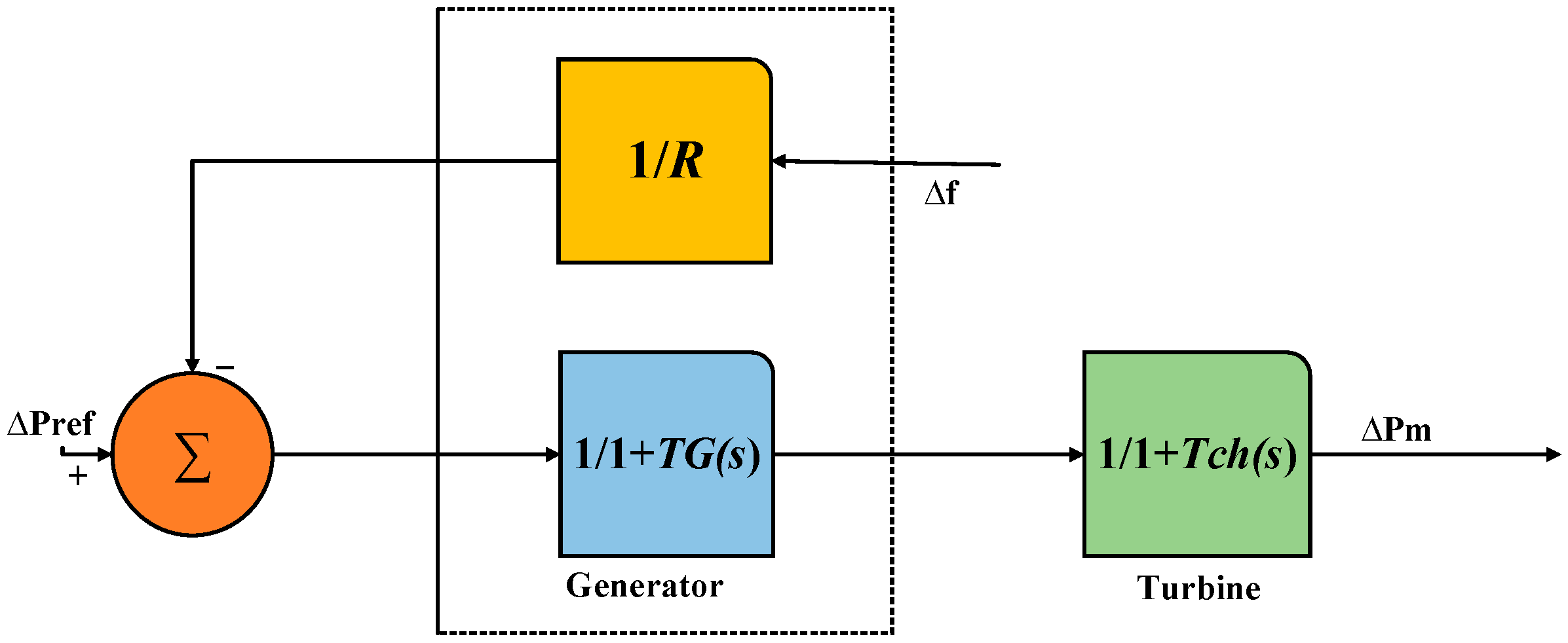
A governor is a mechanical device that measures and controls the speed of a machine engine. The role of the governor is to adjust the median speed for an engine while the load varies. Figure 1 represents the power system’s speed governor block diagram. In Figure 1, transient droop correction Gc(s) with governor time constant TG is included in the speed governing representation. TM denotes the mechanical starting time of the generator, D system damping ratio, R droop gain, Tr turbine time constant, Δf frequency change, ΔP variation in the generator output power, ΔPm variation in the turbine’s mechanical output power, and ΔPL variation in the load power.

2.1.2. Turbine

A turbine is a mechanical device that rotates and converts fluid flow energy, such as steam gas, water, or air, into useful work. Figure 2 shows the turbine model transfer function. In Figure 2, Tch is the time lag in the valve and the switching position that produces the turbine torque.

2.1.3. Load

The electrical grid has several sorts of loads. The load mathematical model block structure is represented in Figure 3, with H representing the generator inertia constant and ΔPe signifying the change in electrical power.
Governor = 1 1 + s T s g
Reheater = 1 + s K r T r 1 + s T r
Steam   generator = 1 1 + s T t
whereas Tsg, Tr, and Tt signify time constants for governor, reheater, and steam turbine. A block diagram for a one-area thermal electrical network is modeled mathematically, as shown in Figure 4.

2.2. Mathematical Modeling of Wind Power System

One of the main nonconventional energy sources is wind power. A wind turbine generator (WTG) of capacity is integrated with an existing power system through the wind power system [29]. The WTG’s dynamic model is given as:
Δ P W T G = 1 T W T G Δ P ω 1 T W T G Δ P W T G
While ΔPWTG represents the output power change of WTG, indicates wind power and TWTG represents the time constant of WTG.
The rotor of a turbine, which is fitted with blades, transforms wind energy into mechanical energy. The rotor’s extracted wind power can be represented mathematically using the following equations [30]:
P r o t o r = 1 2 ρ A V 3 C p
where ρ indicates wind density, A represents the sweeping area, V signifies wind speed (velocity), and Cp represents power coefficient. The following can be used to illustrate the link between input wind speed and active power:
P G W = ρ a 2 V ω 3 C p 2 ( T S R , β )
where β denotes the angle of the blade, TSR tip speed ratio, a area density and swept, Vω wind speed, and rotor efficacy Cp, which is expressed as:
C p = T S R 0.022 β 2 5.6 2 e 0.17 T S R T S R = r p m π D 60 V
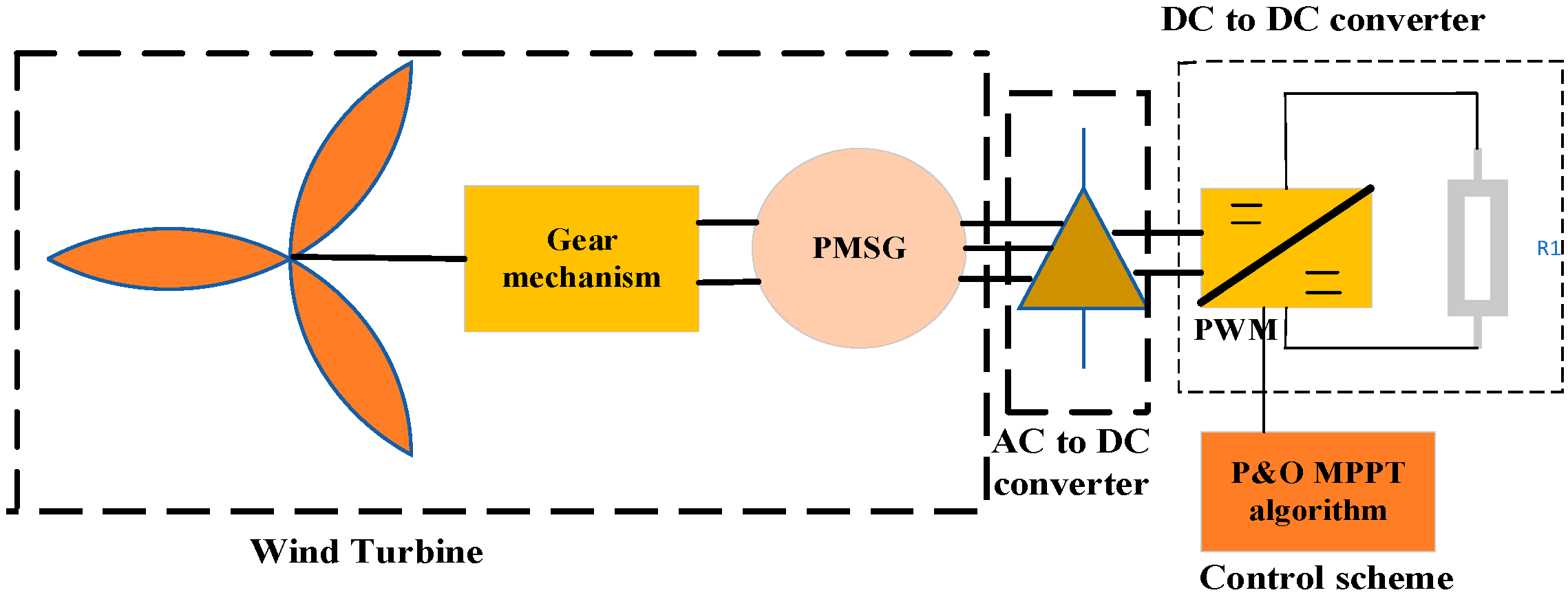
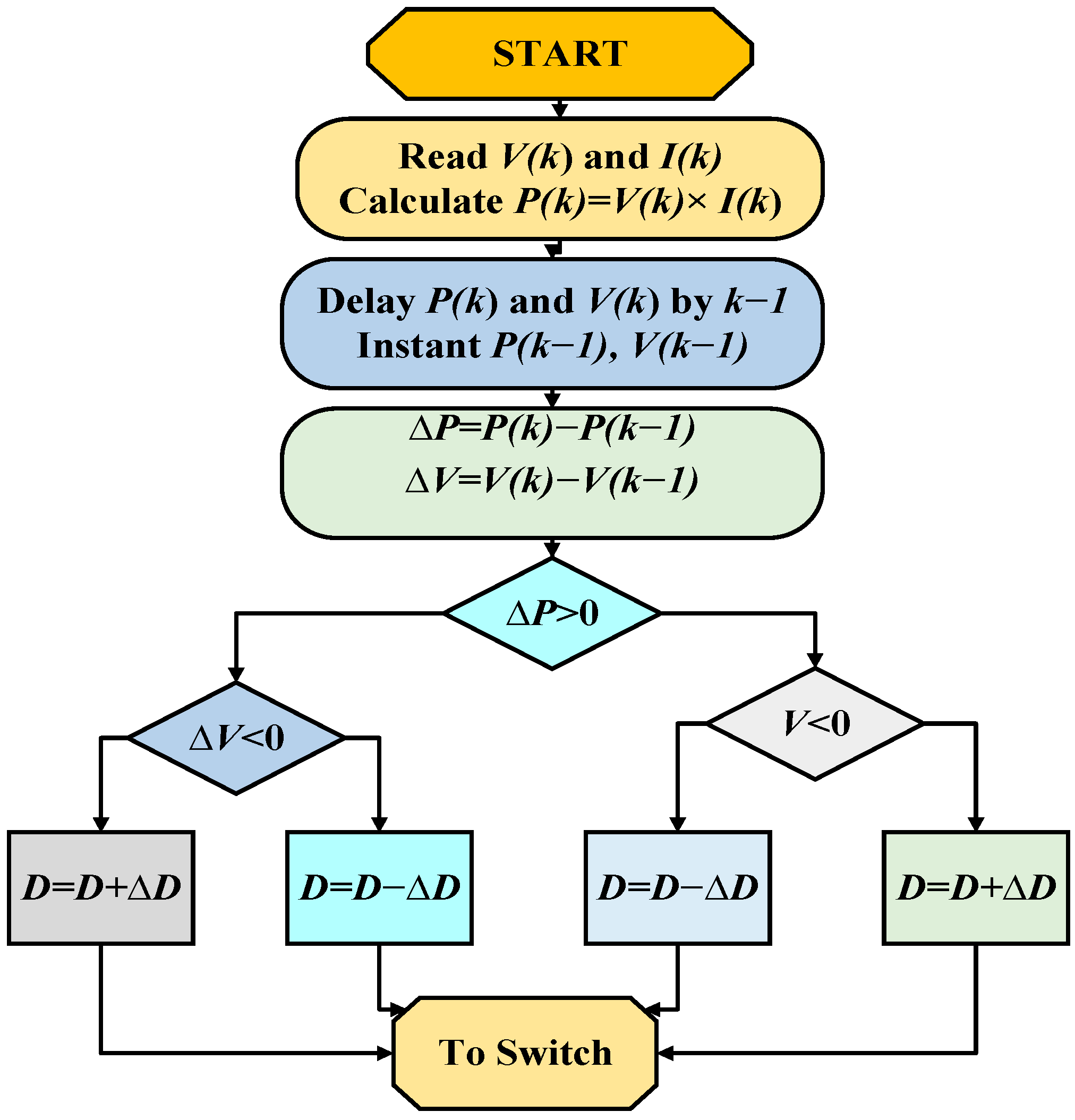
In this article, a permanent magnet synchronous generator (PMSG) is used as the generating output of a wind generator. A block diagram of a wind turbine with PMSG used P & O MPPT with DC-DC boost converter, represented in Figure 5 and Figure 6. This control strategy of a wind turbine with PMSG is designed in MATLAB/Simulink, which will be discussed in Section 3. Mathematically, PMSG wind turbine is represented by the following equations [31,32]. The rotor torque and the generator’s electromechanical torque operate as inputs and produce the output of the mathematical model, which is the rotation speeds.
d w g e n d t = 1 2 H g e n P e l e c w g e n + w 0 D t g ( w g e n w r o t ) k t g Δ θ m
d w r o t d t = 1 2 H r o t P m e c h w r o t + w 0 + D t g ( w g e n w r o t ) + k t g Δ θ m
d ( Δ θ m ) d t = w b a s e ( w g w t )
where wgen represents generator speed, Pelec electrical power, w0 initial speed, wrot turbine speed, and Pmech mechanical power; the steady state occurs when wgen = wrot, so d(Δθ)/dt = 0 and Pelec = Pmech. Dtg, Ktg, and wbase are constants. Where the mass’s geometrical distribution determines the inertial constant, the inertial moment is computed using:
H r o t o r = J r o t o r w r o t o r 2 2 P n ; H g e n = J g e n w g e n 2 2 P n
Regarding the wind rotor, its inertia may be generally calculated using:
J r o t o r = 1 8 m r R 2
mr signifies the mass of the rotor and the R radius of the rotor. Accordingly, the generator’s stator output voltages, d-q, are expressed as:
V d = R d I + L d d I d d t ω g e n L q I q
V q = R q I q + L q d I q d t + ω g e n ( L d I d + φ f )
L denotes inductance of the generator, R resistance, I current in axes d and q, φf permanent magnetic flux, and ωgen rotation speed of PMSG.
ω g e n = P p ω r e f
Pp implies a number of pairs of poles. Electromechanical torque, Tgen, is expressed as:
T g e n = 3 2 P p ω r e f ( L q L d ) i d i q + φ f i q
In Figure 6, V represents voltage, I current, P power, D duty ratio, ΔD change duty ratio, ΔV change in voltage, ΔP change in power, P(K − 1) delay in power, and V(K − 1) delay in voltage.

2.3. Mathematical Modeling of Solar Power System

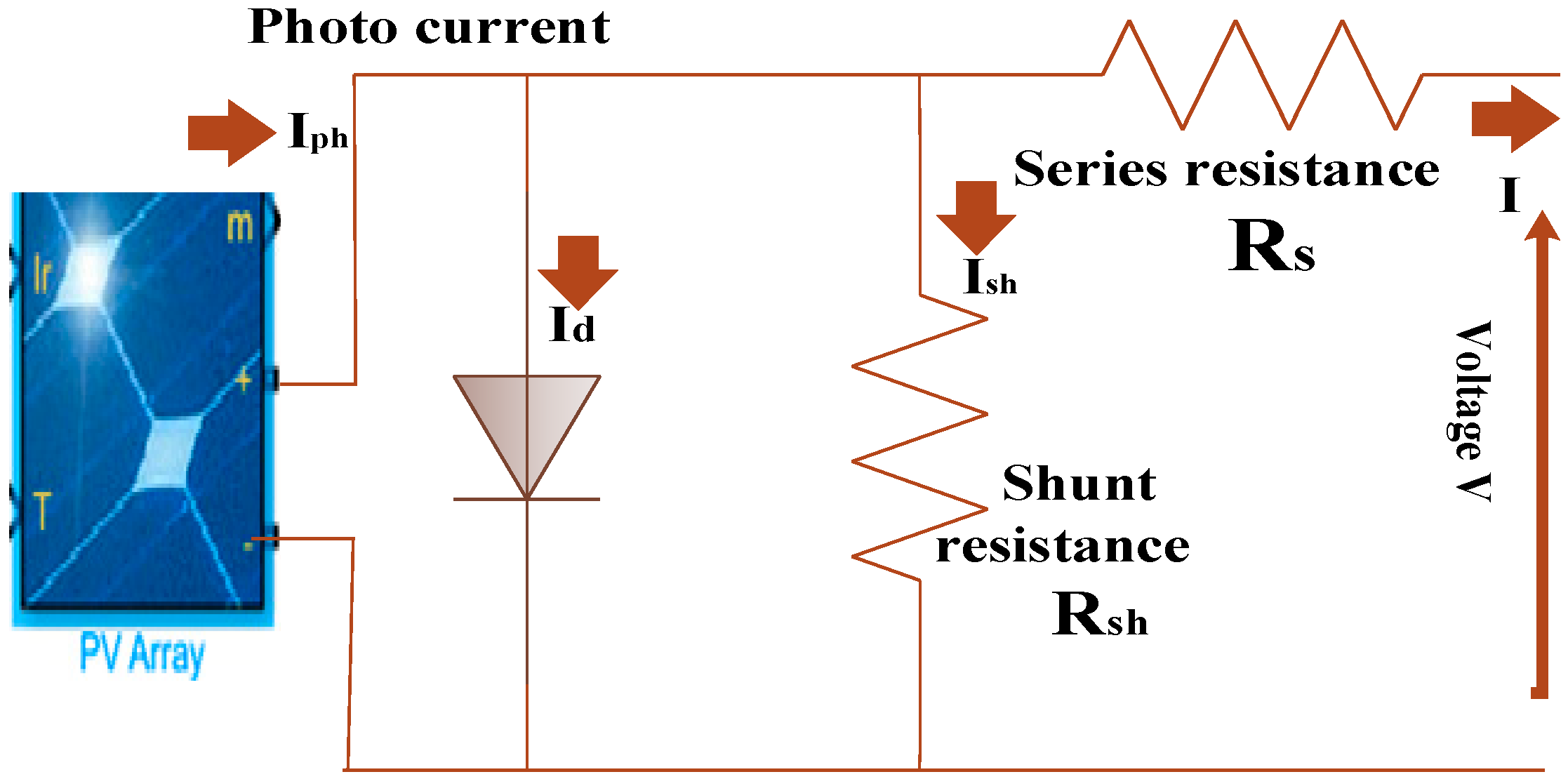
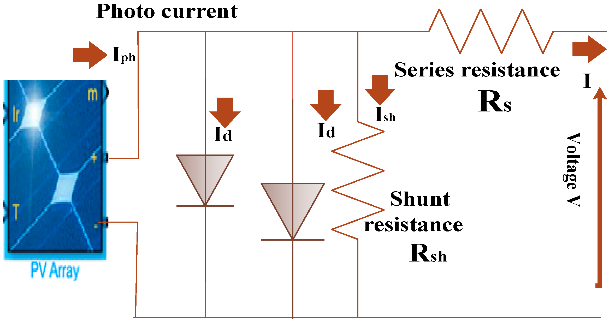
Solar energy is another significant and widely used nonconventional energy source. This energy is transformed into current, which is carried over conductors using photovoltaic panels. By taking into account the relationships between different electronic components, a simplified model of a photovoltaic panel can be created in order to investigate the solar energy employed in power systems [10,33]. Figure 7 depicts the comparable circuit model of a single-diode photovoltaic module. Iph signifies photocurrent, Id diode current, Ish shunt current, Rsh shunt resistance, and Rs series resistance.
The following equations are used to define PV current.
I = I P h I d I R s h
Iph, Id, and IRsh denote photocurrent, diode current, and shunt resistance current. A PV generates a photocurrent at a specific temperature when exposed to solar. Iph has been given as:
I P h = I S C ( S 1000 ) + K t ( T T R )
S indicates solar irradiance, ISC short-circuit current, Kt temperature coefficient, T PV temperature, and TR reference temperature. Id has been given as:
I d = I o exp ( V + I R s n J T ) 1
Terminal voltage is V, Rs is series resistance, I current, n diode ideality factor, and J Boltzmann’s constant. Io saturation current has been given as:
I o = I d ( T T R ) 3 exp q E g n J ( T T R T R T )
Id is diode reverse current, Eg bandgap energy of the cell, and q electron charge. IR has been given as follows:
I R = V + I R s R h
For PV–grid interaction, the first-order transfer function is [33,34]:
Δ P v = K p v 1 + s T p v Δ P s o l a r
Kpv represents the PV gain chosen (one) and Tpv is photovoltaic temperature. Most of the mathematical relationships in one-diode PV systems and two-diode PV systems are the same [35]. Figure 8 depicts an equivalent circuit of a two-diode photovoltaic system.
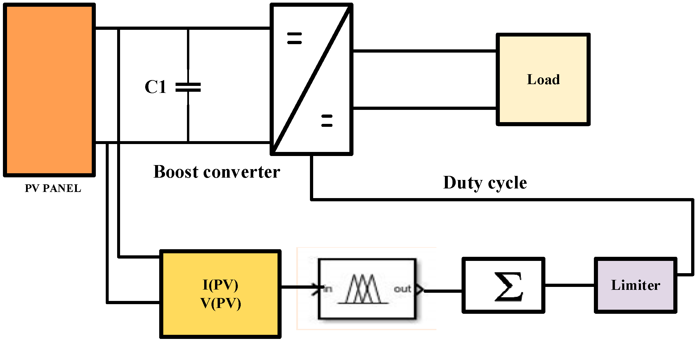
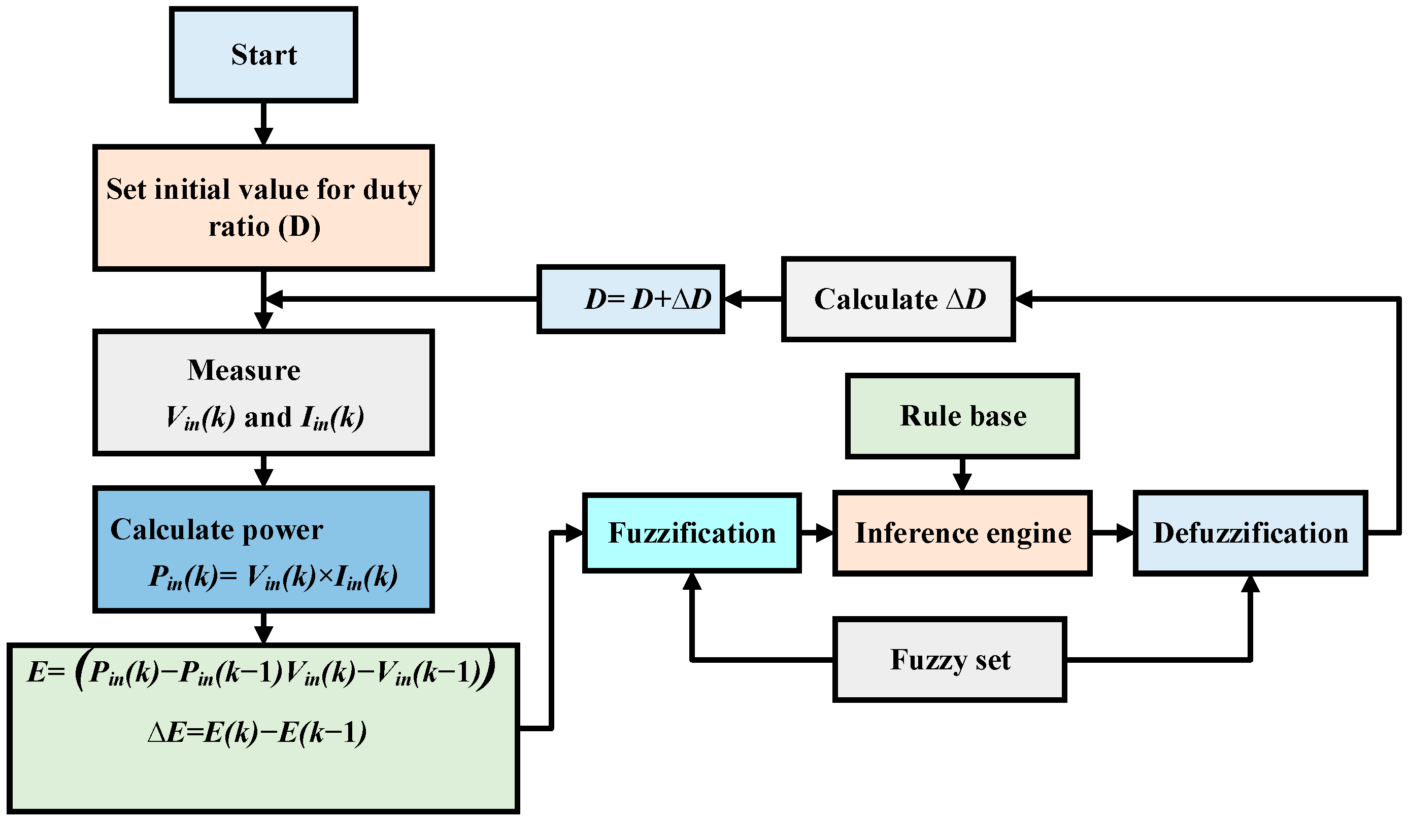
This article is about fuzzy-based MPPT solar PV with a DC-DC boost converter connected with a battery simulated in MATLAB/Simulink. The block diagram and fuzzy MPPT algorithm of this control approach are shown in Figure 9 and Figure 10. This control approach with its Simulink model will be discussed in Section 3. Figure 9 C represents the capacitor, Ipv photovoltaic current, and Vpv photovoltaic voltage. In Figure 10, Iin(k) represents current, Vin(k) voltage, Pin(k) power, Pin (k − 1) previous power, Vin (k − 1) previous voltage, and E instantaneous and previous value of voltage and power.

2.4. Fuel Cell Dynamic Modeling

A fuel cell is an intricate system made up of variables related to fluid, heat, and electrochemistry. The expression for the proportionate relationship between the partial pressure of a gas and its flow through a valve is:
Q H 2 p H 2 = L a n M H 2 = L H 2
QH2 denotes hydrogen molar fluid, PH2 stack hydrogen partial pressure, Lan constant for anode valve, MH2 hydrogen molar mass, and LH2 molar constant for hydrogen valve.
Q H 2 O p H 2 O = L a n M H 2 O = L H 2 O
QH2O signifies water molar fluid, PH2O water vapor partial pressure, MH2O water molar mass, and LH2O molar constancy water valve. Three major contributions influence hydrogen molar flow for hydrogen.
d d t p H 2 = R T V a n ( Q H 2 i n Q H 2 o u t Q H 2 r )
The fundamental electrochemical connection between stack current and hydrogen flow is expressed as:
Q H 2 r = N I 2 F = 2 K r I f c
N denotes the stack’s number of series fuel cells, Ifc fuel cell current, F Faraday’s constant, and Kr modeling constant. Applying Laplace transformation on (23) and (27), the partial pressure of hydrogen is rewritten in the s domain as:
p H 2 = 1 / L H 2 1 + τ H 2 s ( Q H 2 i n 2 K r I f c )
τ H 2 = V a n L H 2 R T
τH2 implies hydrogen time constant, Van anode volume, T stack temperature, and R universal gas constant. Fuel cell output voltage is expressed as:
V c e l l = E + η a c t + η o h m
When expressed with regard to gas molarities, Nernst voltage is:
E = N E 0 + R T 2 F log p H 2 p O 2 0.5 p H 2 O
E signifies Nerst’s voltage, E0 cell open voltage, Vcell cell voltage, and ηact ohm overvoltage.

2.5. Two-Area Tie-Line Modeling

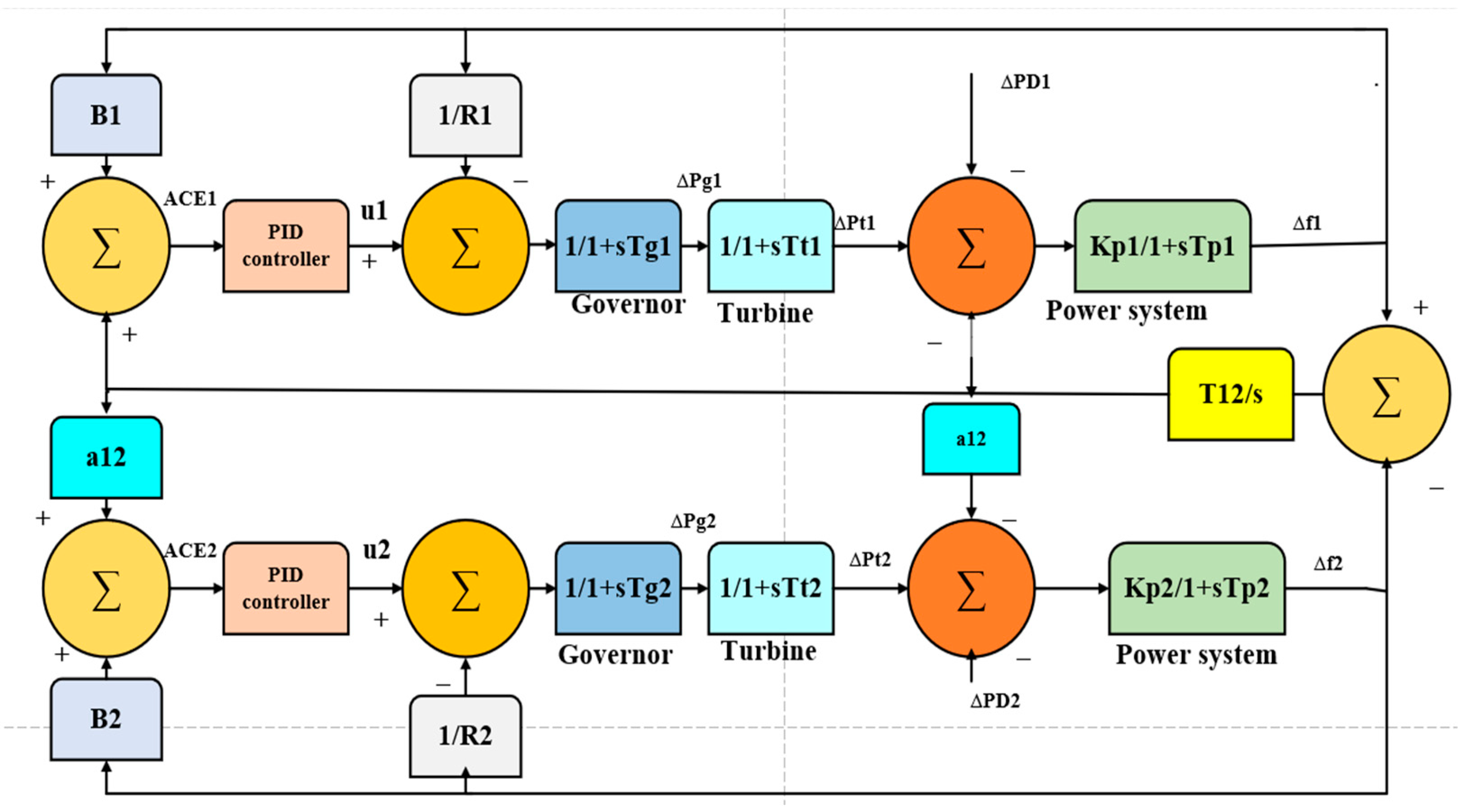
As seen in Figure 11, the electrical network proposed in this study comprises a two-area thermal power network. Each region’s turbine, generator, and speed-regulating device, which have two outputs and three inputs, make up the main components. Figure 11 shows the block diagram of two-area tie-line IPS. Consequently, a PID controller is applied to both of the model’s components. In Figure 11, input control signals are denoted by u1 and u2, power change in demands ΔPD1 and ΔPD2, ΔPg is the power change in the generator, ΔPt power change in the turbine, output area control errors ACE1 and ACE2, frequency bias coefficients B1 and B2, and deviation in system frequencies Δf1 and Δf2.
When a two-area power network is used, frequency bias coefficients B1 and B2 are determined using:
B 1 = 1 R 1 + D 1
B 2 = 1 R 2 + D 2
A C E 1 = B 1 Δ f 1 + Δ P t i e 1
A C E 2 = B 2 Δ f 2 + Δ P t i e 2
The proposed networks are designed using transfer functions and suggested block schemes with techniques; the Simulink models are developed for investigation utilizing MATLAB/Simulink environment for frequency control. The PID controller parameters are optimized and implemented by writing a separate PSO technique—coding mfile. The nominal values for the proposed networks are given in Appendix A, Appendix B and Appendix D.

3. Proposed Control Strategy

This section will explain the proposed study, the proposed study in this article being a one-area thermal power system connected with a PMSG wind turbine using P & O MPPT algorithm with DC-DC boost converter, a fuzzy-based MPPT solar PV connected with a battery through DC-DC boost converter and fuel cell, and a dual-area tie-line IPS. The PSO approach is utilized to tune PID controller values. The proposed control study is simulated using MATLAB/Simulink for investigation and regulation of frequency.

3.1. PID Controller

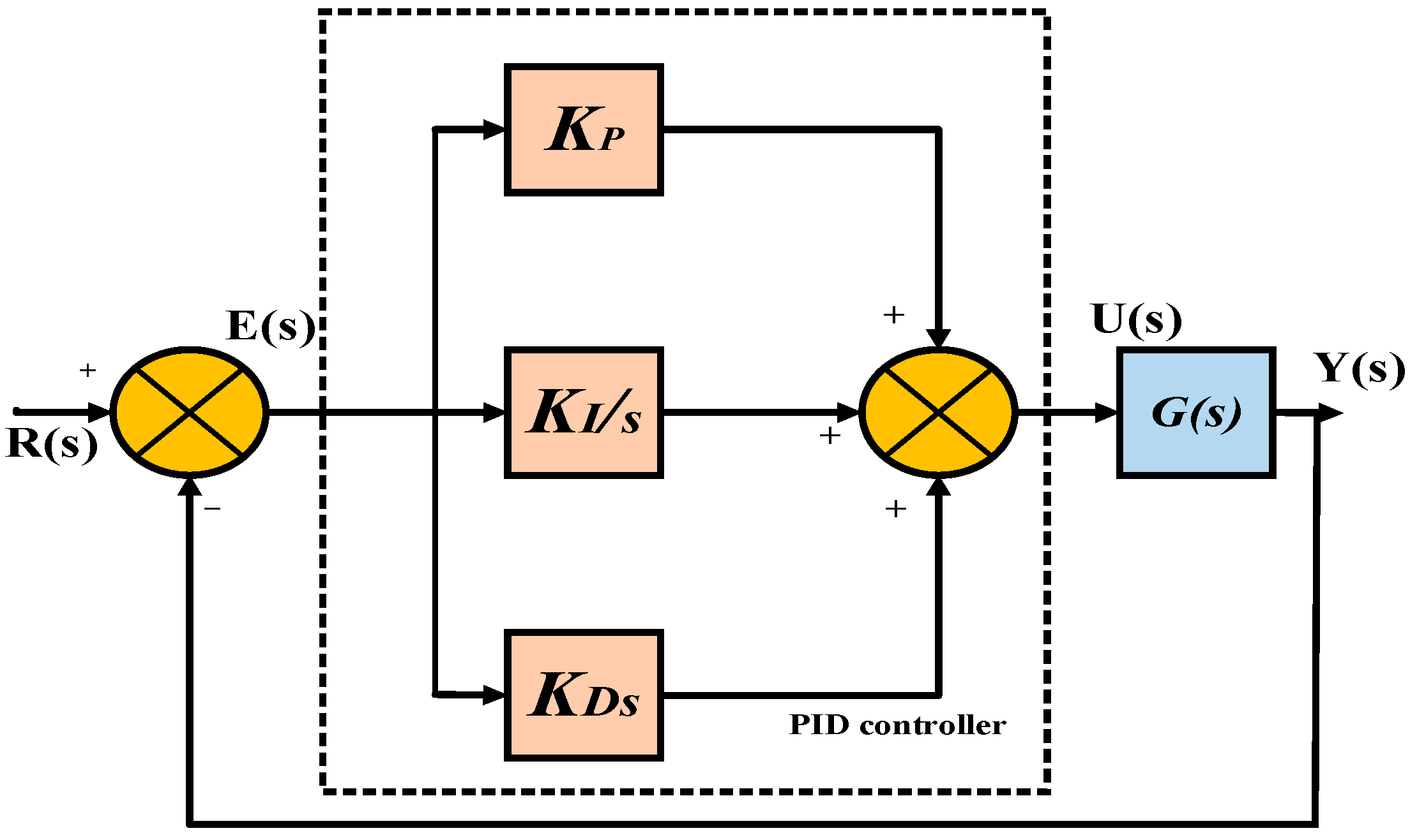
Finding the right combination of controls to allow the system to attain the desired state with the fewest potential deviations continuously is a controller’s main goal. PID controllers are widely utilized in control and automation fields because of their improved features and tried-and-true design processes [36]. The output it produces is the total of the derivatives and proportionately integral controller outputs. The PID controller’s basic configuration is depicted in Figure 12. In Figure 12, R(s) represents the input signal, E(s) is the error signal, U(s) is a control signal, and Y(s) denotes the output signal.
Mathematically:
u ( t ) e ( t ) + e ( t ) + d d t e ( t )
The transfer function is:
U ( s ) E ( s ) = K P + K I s + K D s
KP KI, and KD imply controller constants. By simplification, the transfer function is:
K P 1 + K I K P s + K D K P s K P 1 + 1 T i s + T D s T i = K P K I & T D = K D K p
PID controller considers errors from the past, present, and future while determining its control value. The two-area tie-line IPS and single-area multi-source electrical network is combined with the recommended PID controller in an effort to keep the system operating at its desired frequency and reduce power fluctuations.

3.2. Objective Function

The objective function is a scale that can help in optimizing the controller gain settings. This article uses ITAE as the objective function to adjust the gain values of the PID controller. It can be represented mathematically as [8]:
I T A E = t = 0 t = f i n a l Δ f × t × d t
The following discusses the models for simulation of the recommended approach tunings using the PSO algorithm utilizing ITAE as a cost function.

3.3. Multi-Source Single-Area Power Network

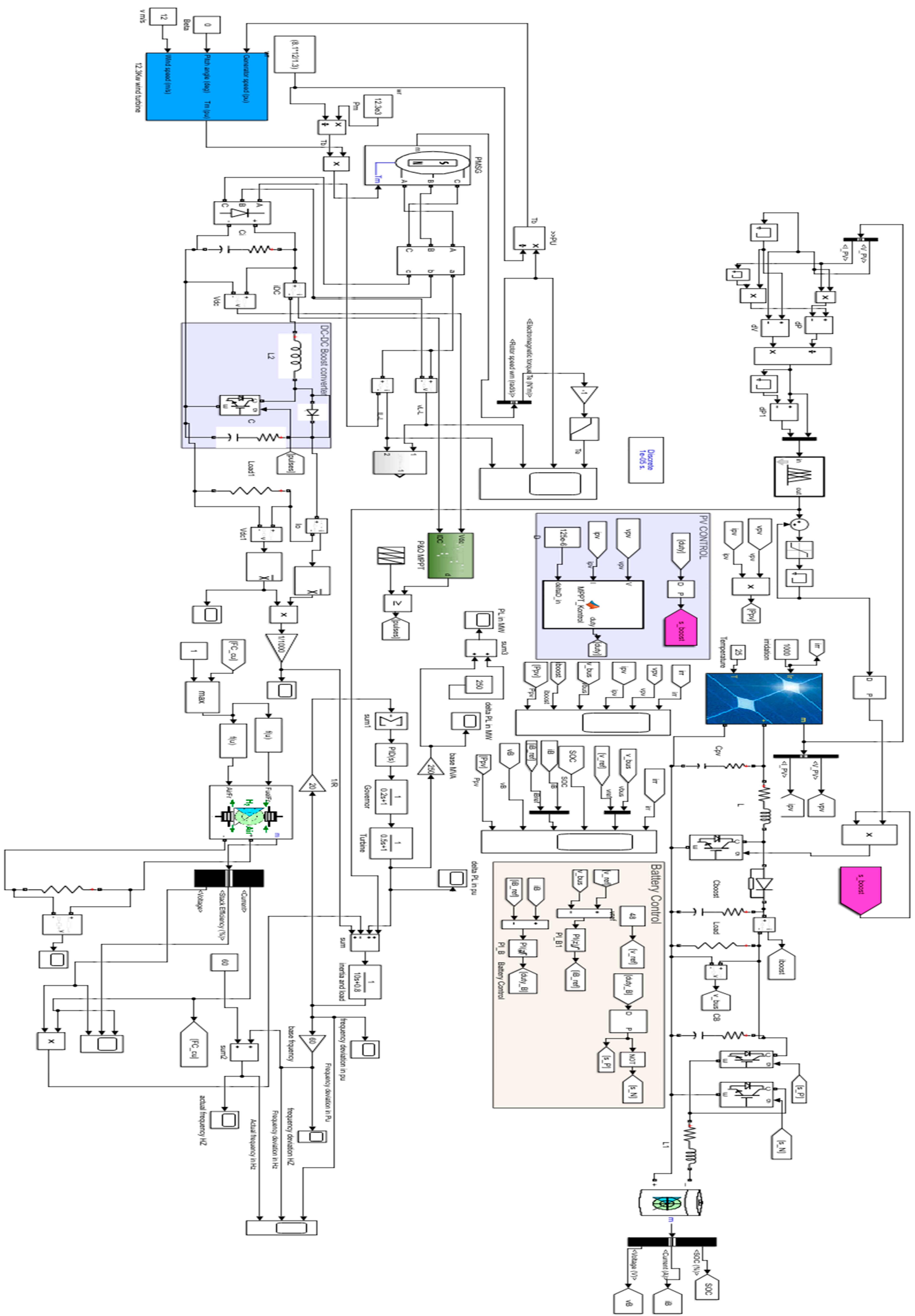
The PSO code was created in (.m file), and a single area of the electrical system model connected with RESs was designed in Simulink program surroundings. Figure 13 shows the Simulink model for a single-area multi-source power network.
Appendix A represents parameter values of a one-area thermal power network, whereas Appendix B presents the parameter values and electrical characteristics of wind, fuel cell, and solar power sources.
A diagram of solar PV fuzzy-based MPPT algorithm and a wind turbine with PMSG-based P & O MPPT algorithm is given above in Section 2. Table 2 and Table 3 below show the fuzzy rule solar PV MPPT and fuzzy rule ranges, membership functions, and their types, respectively. In Table 2, NB represents the negative big, NS negative small, ZE zero, PS positive small, and PB positive big.
PSO approach operators are utilized to find optimal values of the PID controller. Appendix C represents PSO operators and Table 4 represents optimal gain PID controller parameters.

3.4. LFC in an Interlined Dual-Area Tie-Line Power Network

Power is growing more and more necessary for the commercial, industrial, and residential sectors. Integration of renewable energy is a better choice because it lessens reliance. By deregulating the power grid, the standard operating conditions can be altered. Because of this, distributed generation in two-area energy networks has garnered significant interest. In order to accommodate an excessive load, the majority of the contemporary power system consists of several control zones with different generating sources along with nonidentical capabilities. Any difference between demand and supply leads to an unintentional deviation of area frequency from a predefined level, which, in turn, results in power-sharing with neighboring control areas.
The two-area power network tie-line linked model (AGC) employed for the investigation comprises two thermal units. Electric power can be transmitted across the interlinked sectors through tie lines. When unfavorable conditions arise, such as severe load interruptions, the control unit keeps an eye on variations in tie-line power and frequency attempts to restore the system to normal. Consequently, ITAE is thought of as a goal function and is expressed as:
I T A E = 0 t ( Δ f 1 + Δ f 2 + Δ P t i e ) × t × d t
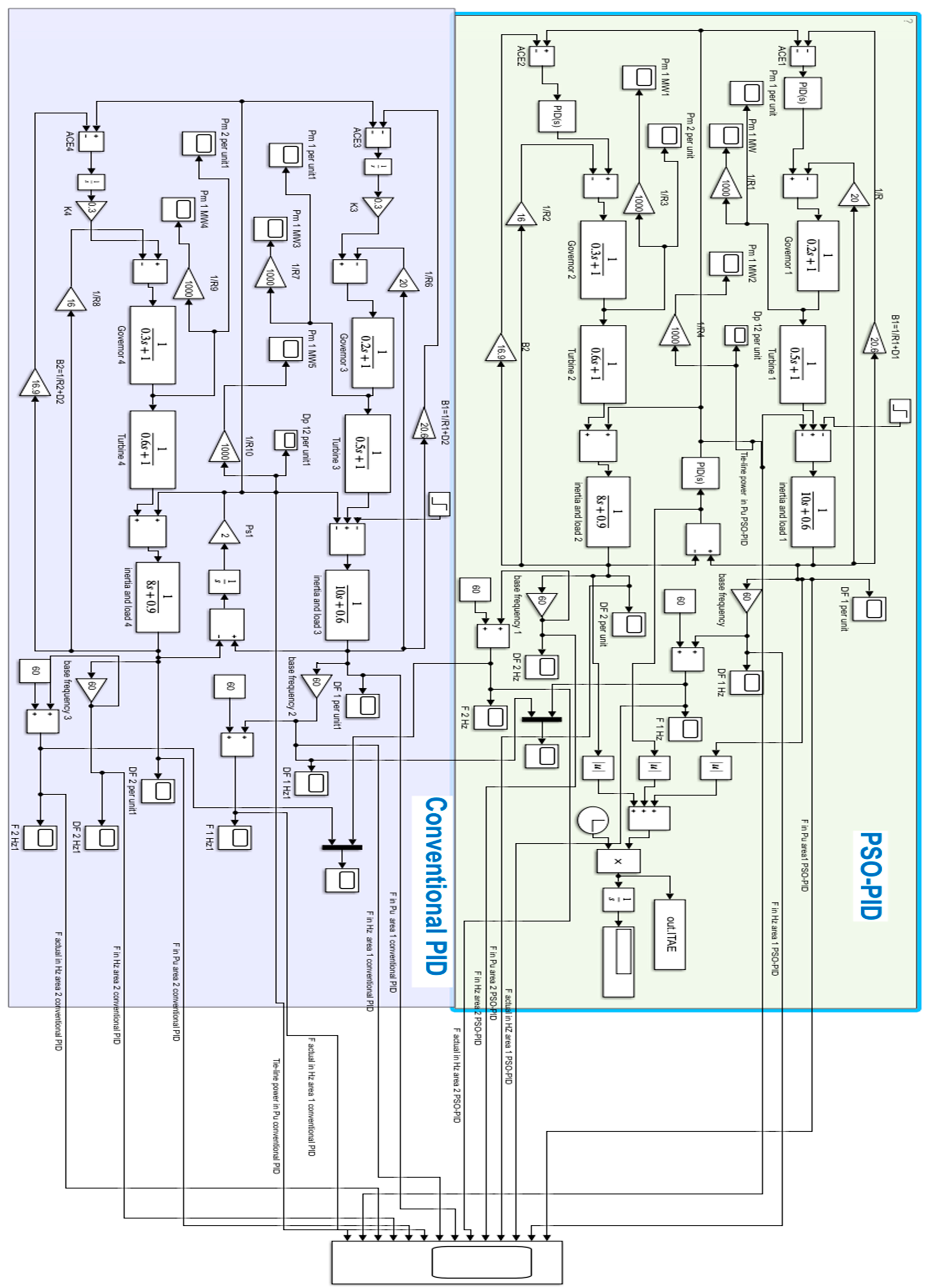
where Δf1 and Δf2 represent change in frequency in area 1 and area 2 and ΔPtie is tie-line frequency variation, respectively. A diagram of this control strategy with the mathematical model is given in Section 2. Appendix D provides the pertinent model values for a two-area power network. The MATLAB/Simulink model of this proposed strategy is shown in Figure 14.
The PSO’s parameters are configured as indicated in Appendix E, and Table 5 shows the optimized values of the PSO-PID controller.

3.5. Proposed Algorithm Particle Swarm Optimization (PSO)

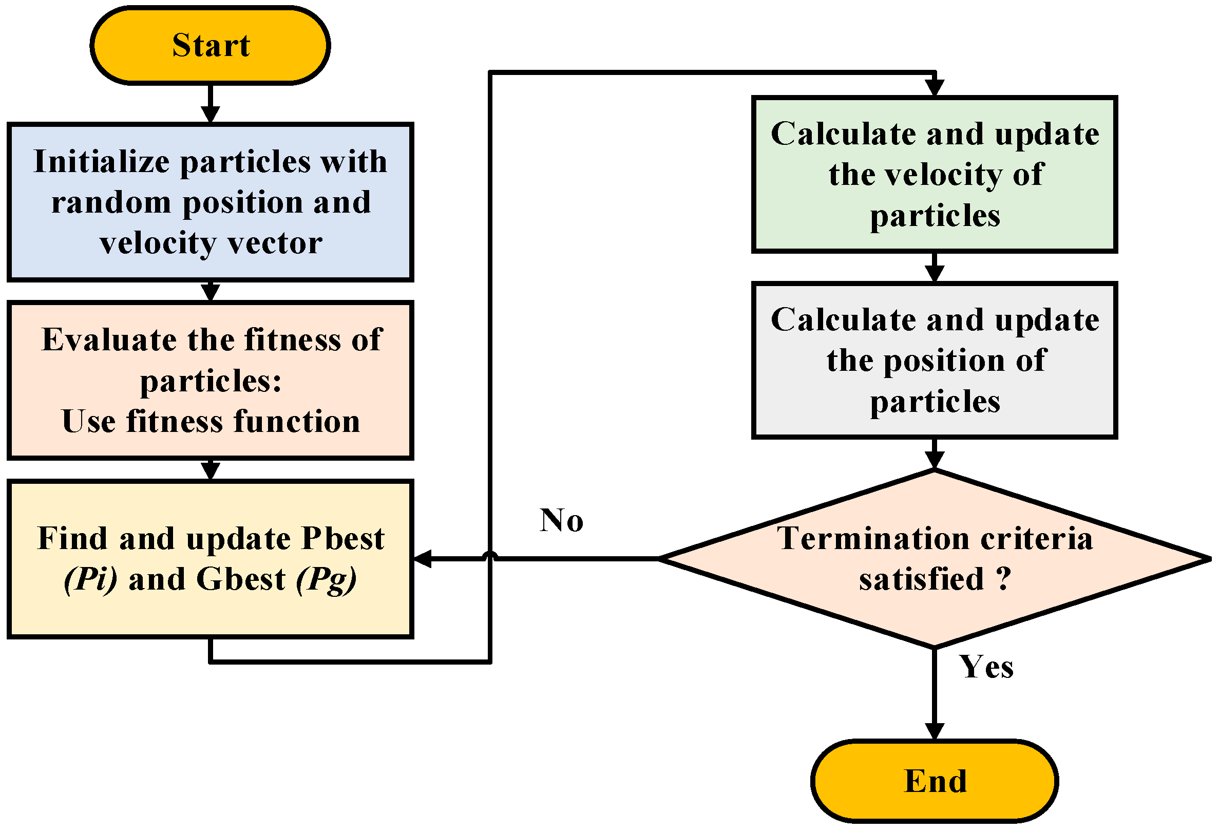
Dr. Kennedy and Eberhart developed the PSO algorithm in 1995, drawing inspiration from the community behavior observed in the fish schooling and bird flocking processes. In the PSO technique, every solution is referred to as a “particle” in the search field. The goal function’s fitness values determine the tuning procedure. The trajectory of the particle is guided by its momentum as it searches the space for the optimal values, both globally and individually. The swarm is first assembled from a collection of random particles, and iterations are changed to search for optimization. Global best and personal best principles are applied to each particle to attain optimal gain values. The best answer, known as the local best, has been reached after each cycle. The ultimate best value that is obtained after optimizing each local best value is referred to as the global best [7].
In the D-dimensional search space, the population contains N particles, and the position of the i t h particle is presented as X i = ( x i 1 , x i 2 x i D ) in the D-dimensional space, with velocity V i = ( v i 1 , v i 2 v i D ) , i = 1 , 2 N . The next generation of particles’ optimal values, both individually and collectively, are determined while updating the particles’ positions and velocities using an iteration algorithm. The progression diagram for the PID controller tuning process is shown in Figure 15.
V i d ( k + 1 ) = w V i d ( k ) + c 1 r 1 ( P i d ( k ) X i d ( k ) ) + c 2 r 2 ( P g d ( k ) X i d ( k )
X i d ( k + 1 ) = X i d ( k ) + V i d ( k + 1 )
w denotes inertia factor, r1 and r2 random numbers in [0, 1], c1 and c2 learning factors, and Pi and Pg are both the current iteration’s individual ideal position as well as the global optimal position.

4. Simulation Results

This section demonstrates the superiority of the proposed control method by discussing the results of employing a PSO-PID controller and comparing it with a conventional PID controller. From results carried out using MATLAB 2020a, the suggested power system is examined in two scenarios:
  • System parameter variations in one-area multi-source power network and dual-area tie-linked power system.
  • Load variations are in double-area tie-line linked power systems only.

4.1. Multi-Source One-Area Power Network

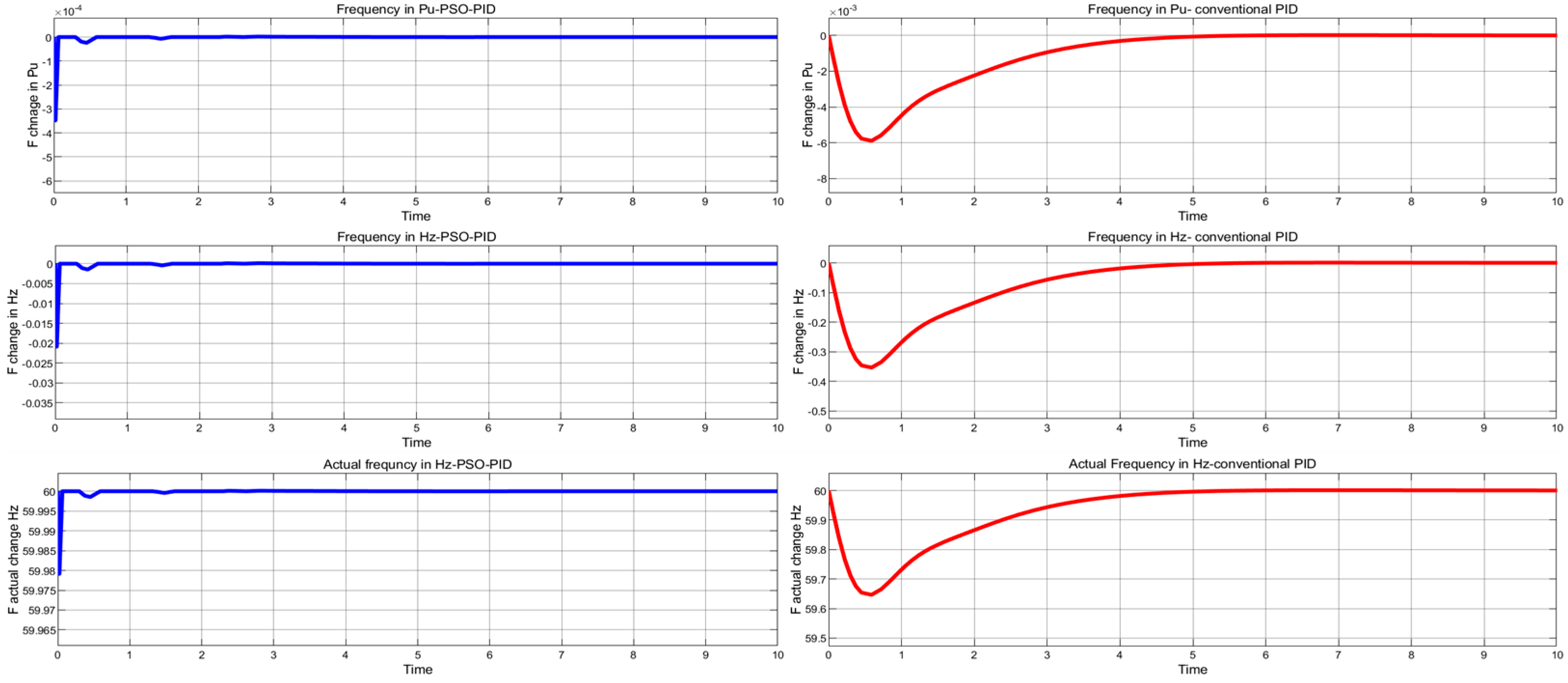
The result obtained with the PSO-PID controller is presented in Figure 16. Blue lines show PSO-PID controller responses to frequency and red lines show conventional PID control system frequency outputs. The proposed one-area multi-source power network exhibits significantly better transient responses in terms of actual frequency, frequency deviation in Hz, and frequency variation in Pu. As we notice, the PSO algorithm has tuned the parameters of PID controllers and generated optimum responses in terms of extremely minimal undershoot and very short response time compared to conventional PID controllers.

Robustness Evaluations (Case Study 1)

Constant fluctuations in system parameters can significantly harm the performance of closed-loop systems. Experiments are therefore conducted to explore the effects of parametric uncertainty on the system. Each system parameter is changed by around ±50% from its original value to achieve this. A one-area multi-source power network model is taken into consideration for two alternative scenarios of parameter uncertainty, as shown in Table 6.
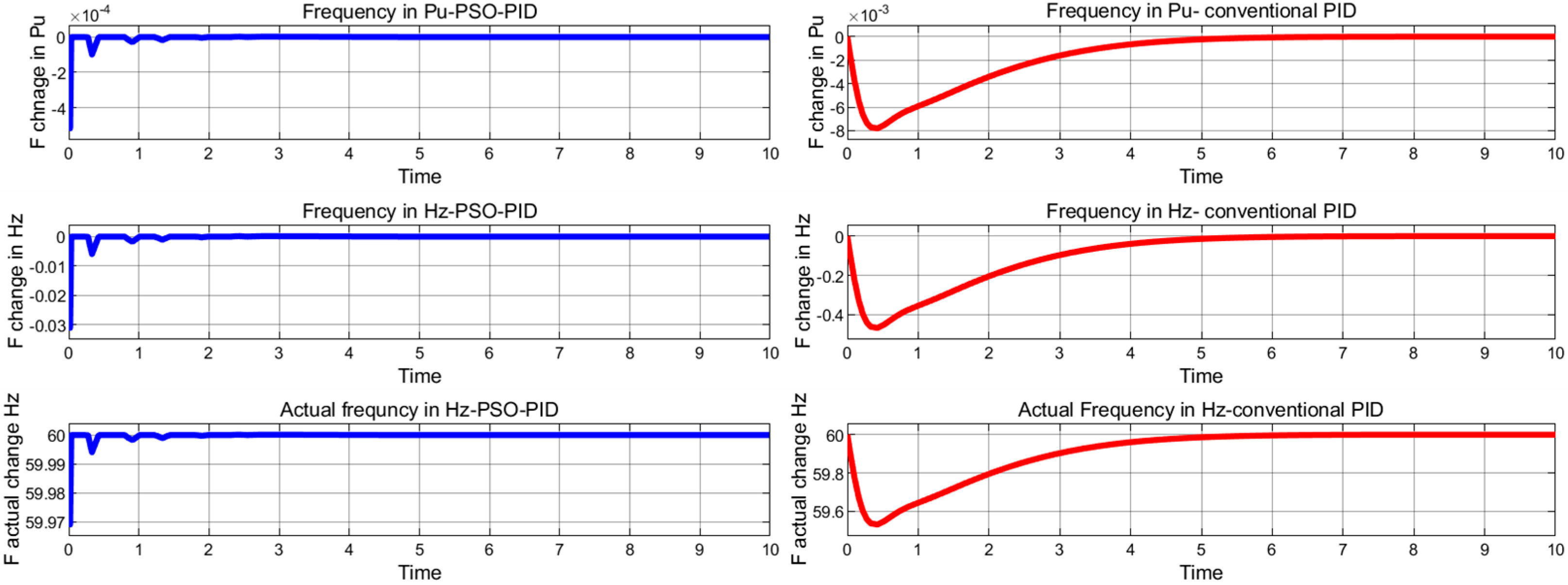
Figure 17 and Figure 18 show the frequency outputs of the single-area multi-source electrical system under parametric uncertainty. A PSO-PID controller frequency exhibits superiority over the standard PID controller’s frequency response, with reduced overshoot and undershoot and a remarkably short settling time. Table 7 shows the frequency response signal parameters of the one-area multi-source power system.

4.2. Two-Area Tie-Line Interconnected Power System

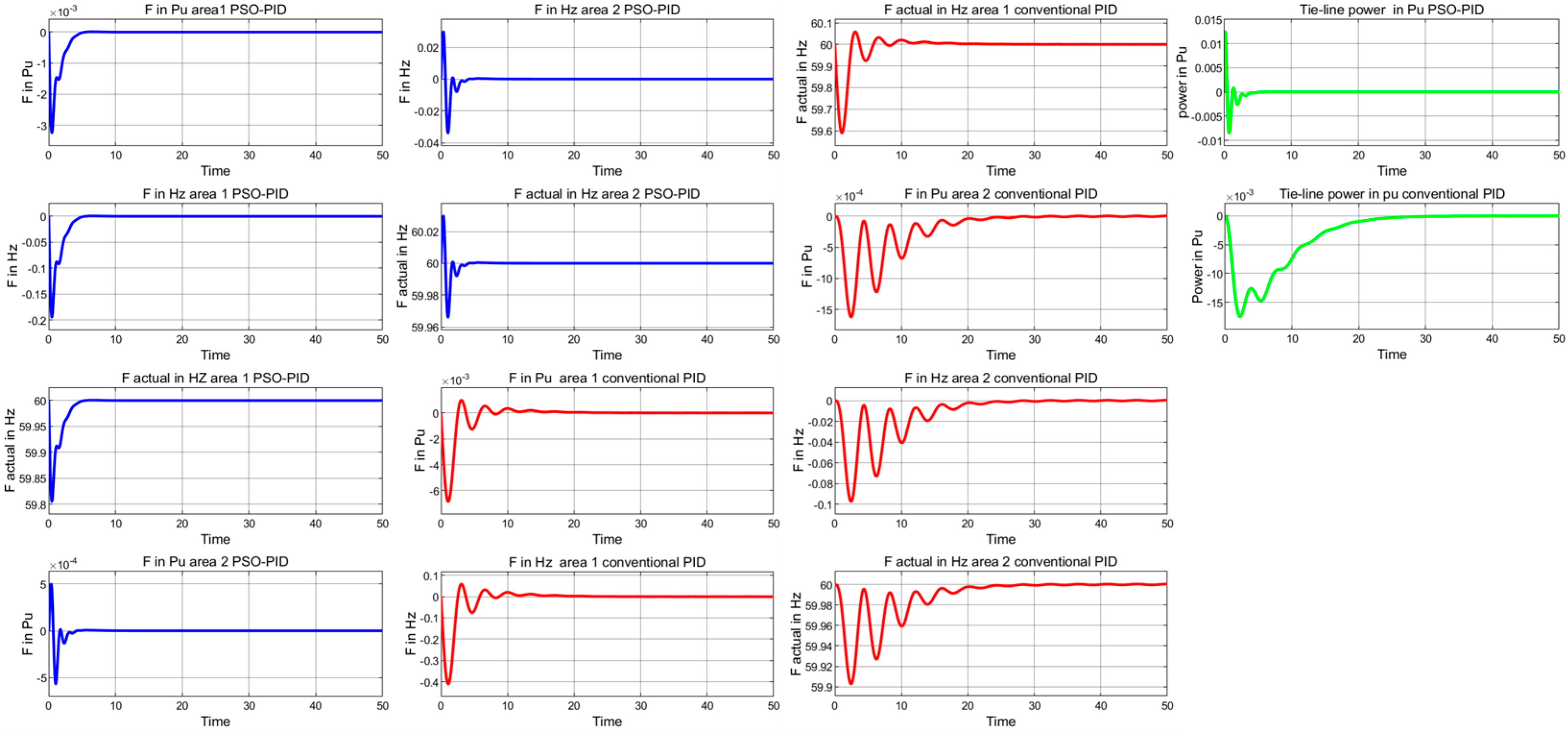
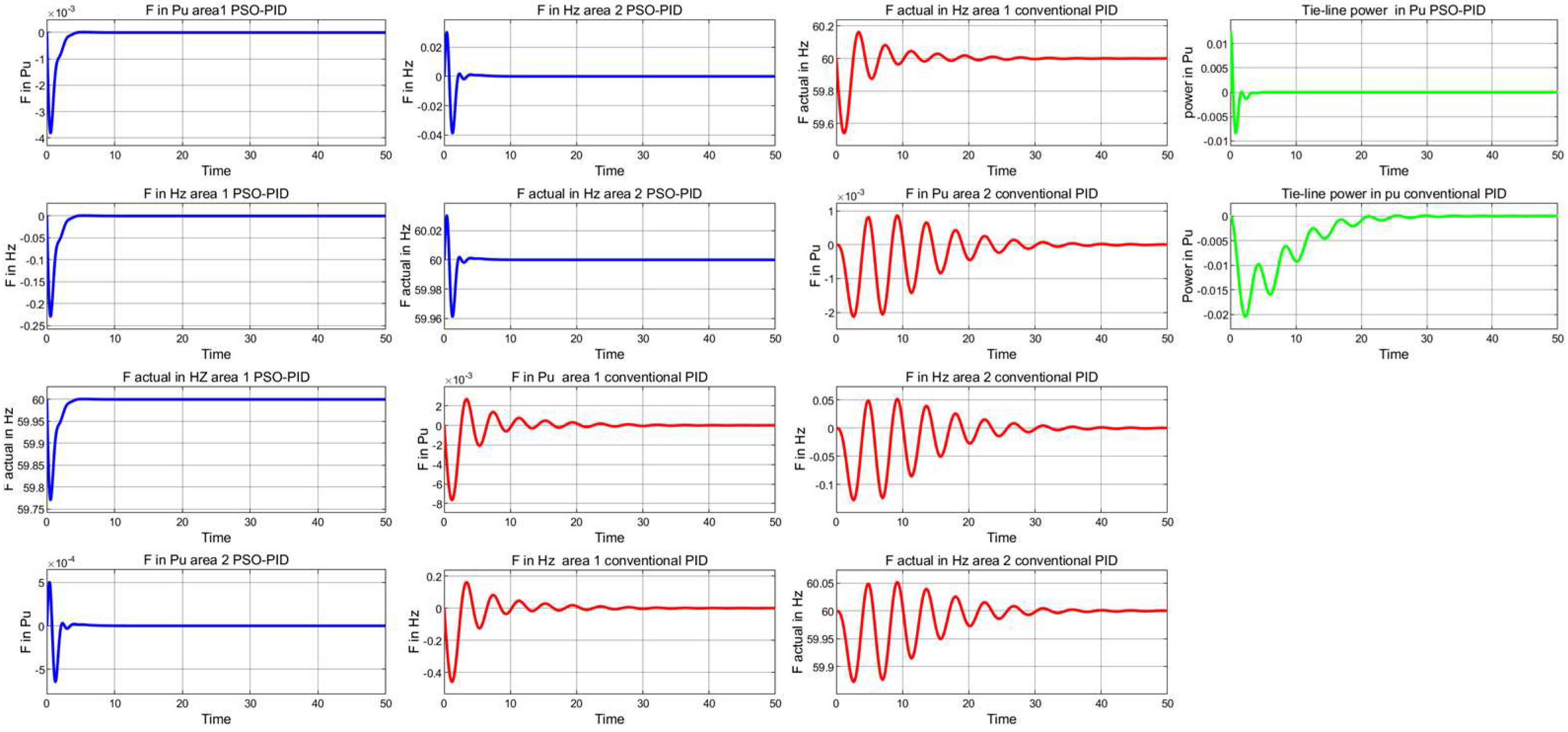
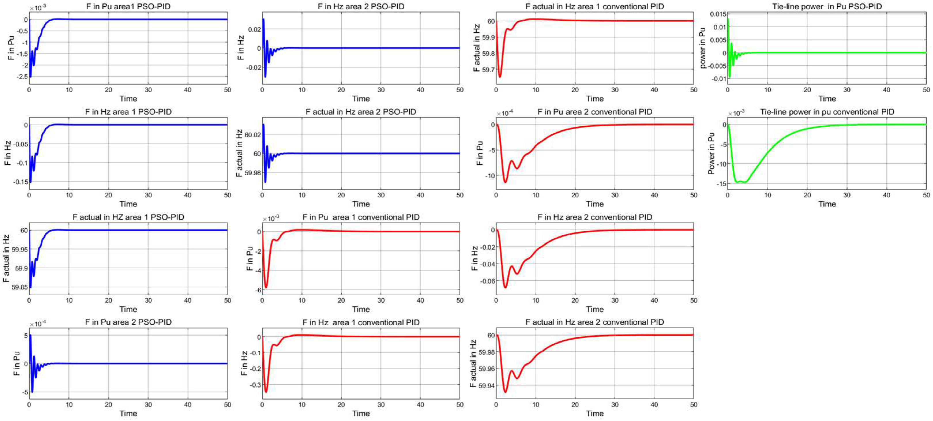
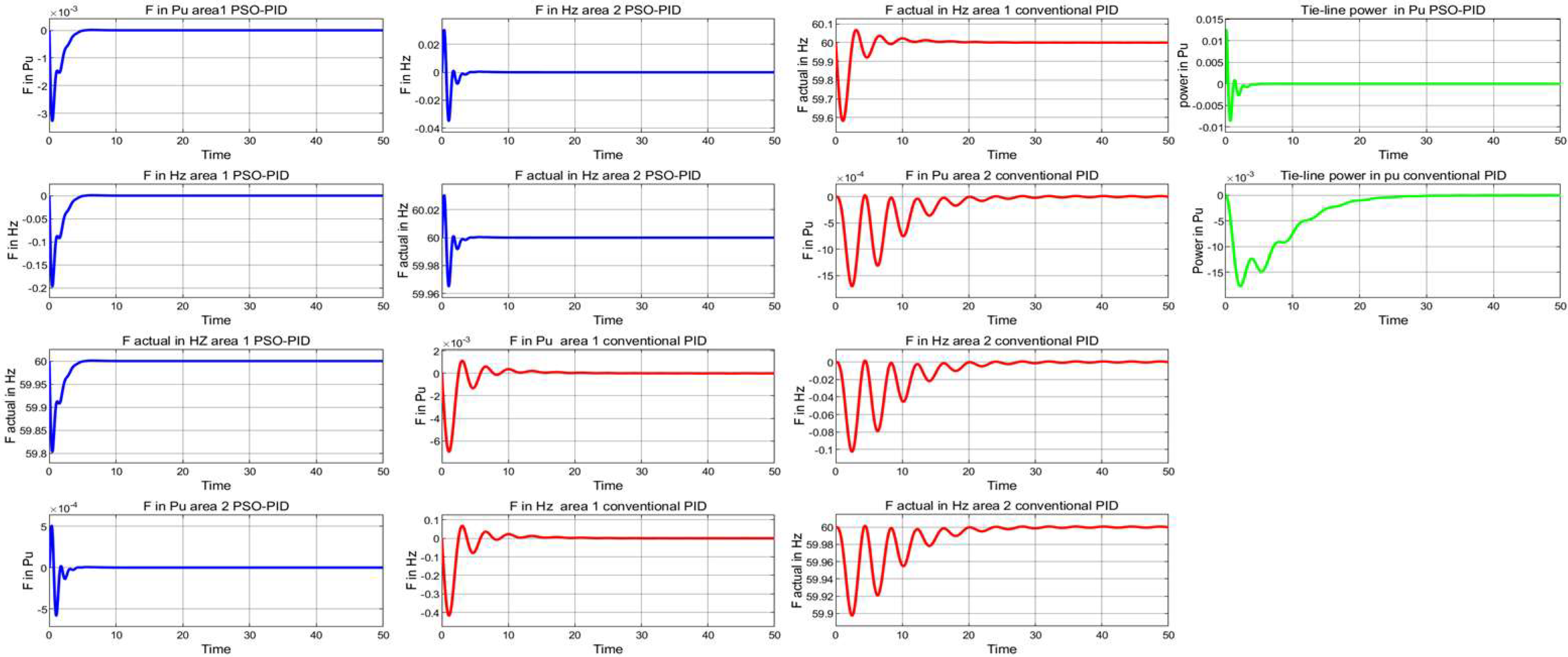
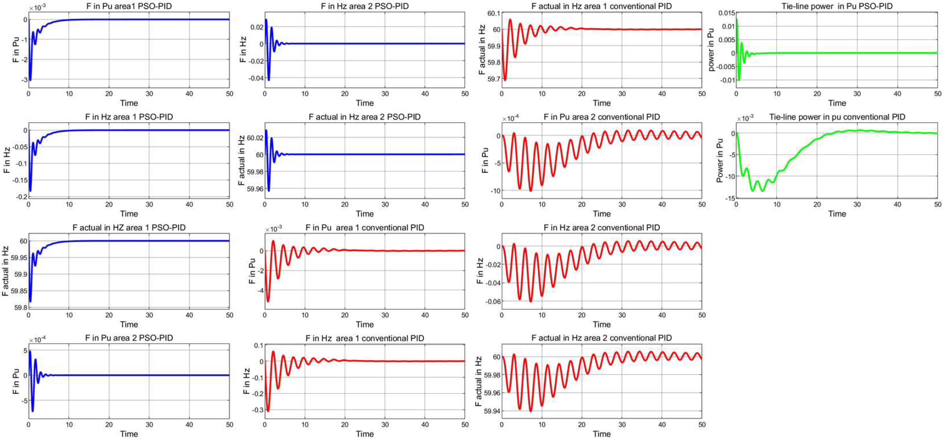
Results achieved with the PSO-PID controller are shown in Figure 19. Blue lines represent PSO-PID controller frequency responses in areas 1 and 2, red lines represent conventional PID controller frequency responses in areas 1 and 2, while green lines represent tie-line power variations in areas 1 and 2 with and without PSO-PID controller, respectively. The proposed two-area tie-line linked power network exhibits much better transient responses in terms of actual frequency, tie-line power deviation, deviation of frequency in Pu, and frequency deviation in Hz. As we see, the PSO algorithm optimized the PID controller’s parameters. It generated the optimum response in terms of extremely minimal undershoot and very short response time compared with the conventional PID controller.

4.2.1. Robustness Evaluations (Case Study 1)

The stability of a system is impacted by fluctuation. In order to achieve an appropriate level of resilience, the LFC system must have necessary control action against parameter uncertainties in a controlled system.
As a result, 13 scenarios for parameter uncertainties of the testbed network are taken in order to evaluate the resilience of the suggested PSO-PID control configuration tuned by PSO as an LFC network within a double-area interlinked power network. Each system parameter is independently varied by (+ and −) 50% from its nominal value to begin this examination.
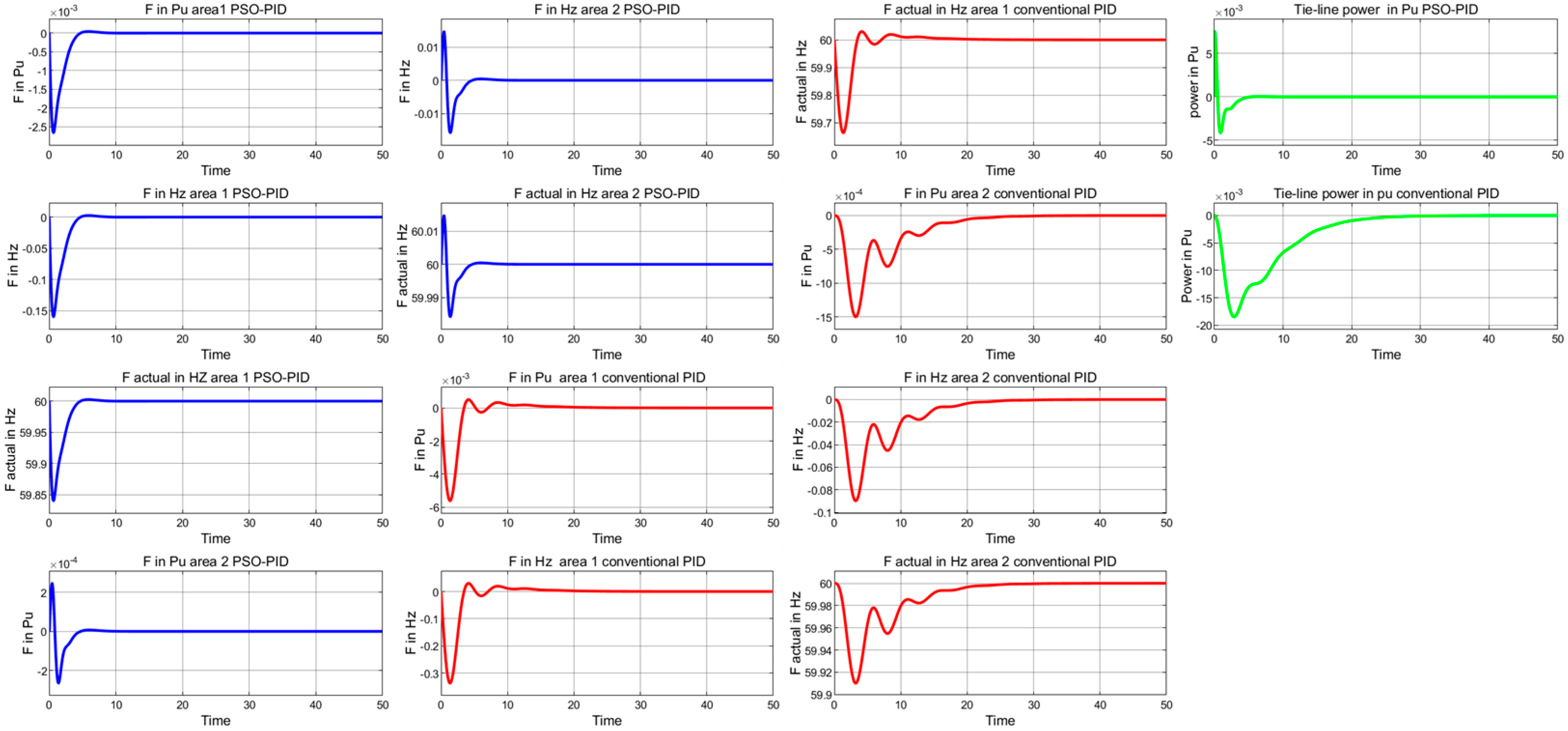
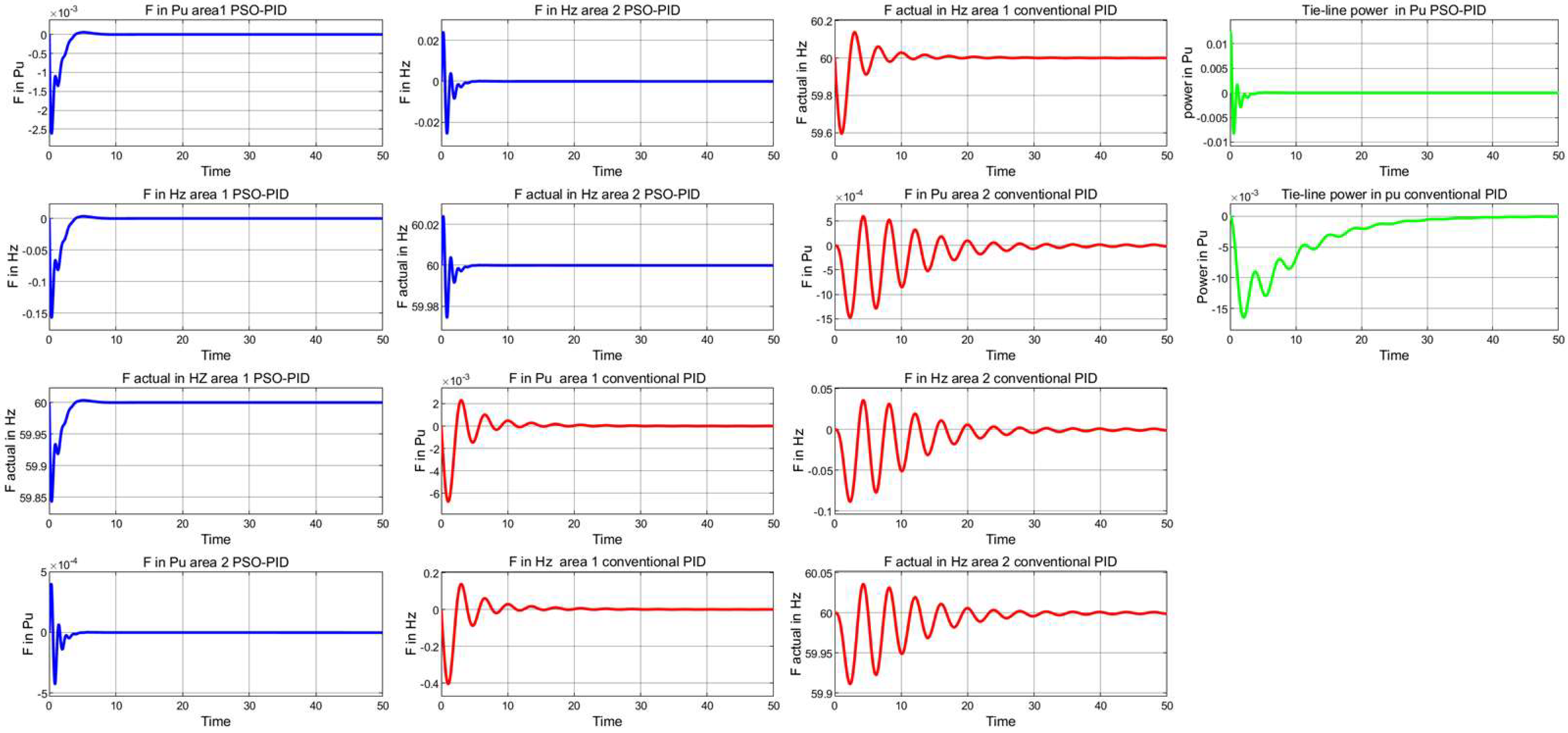
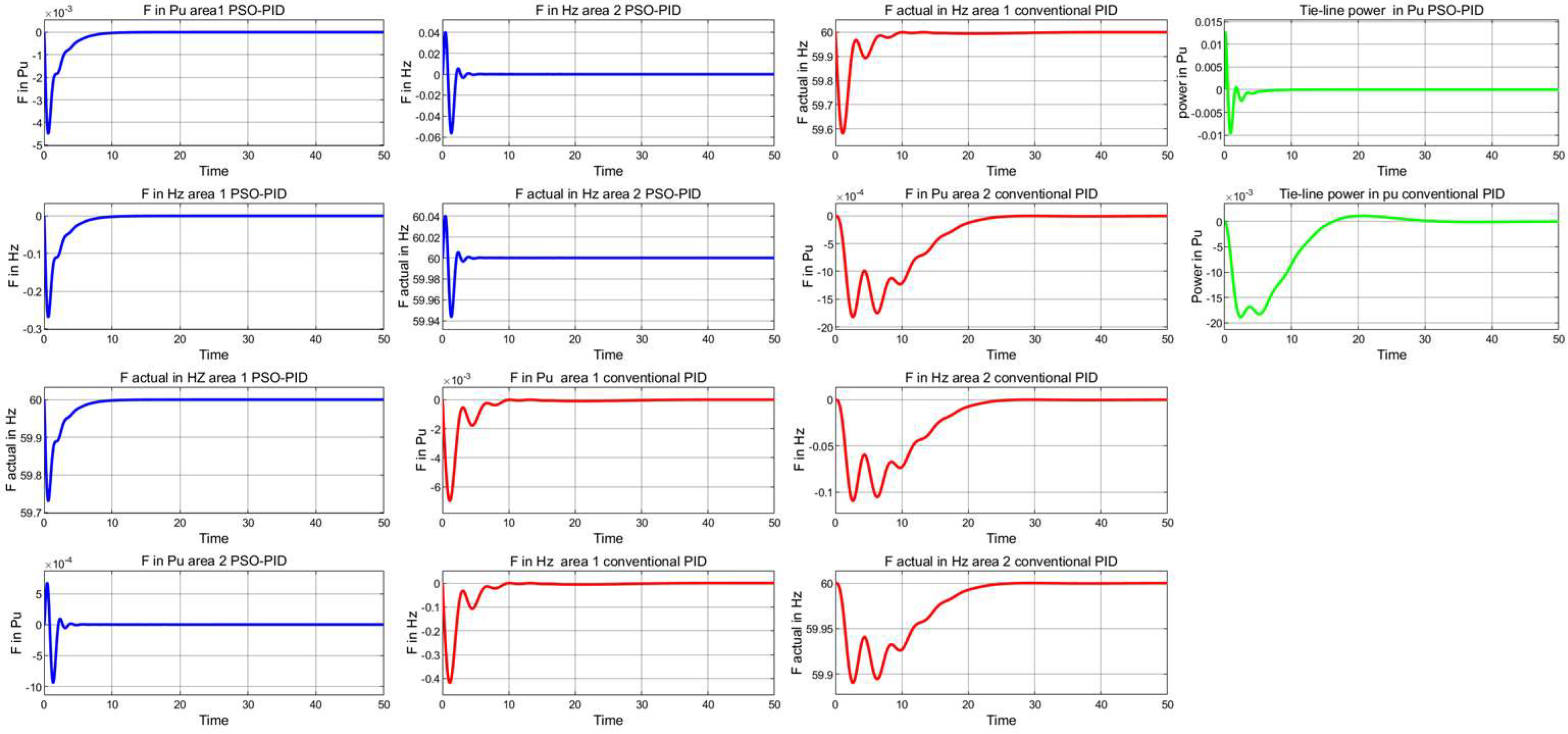
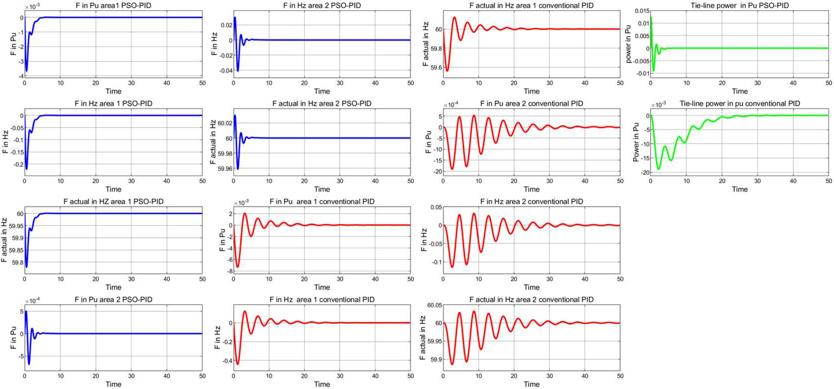
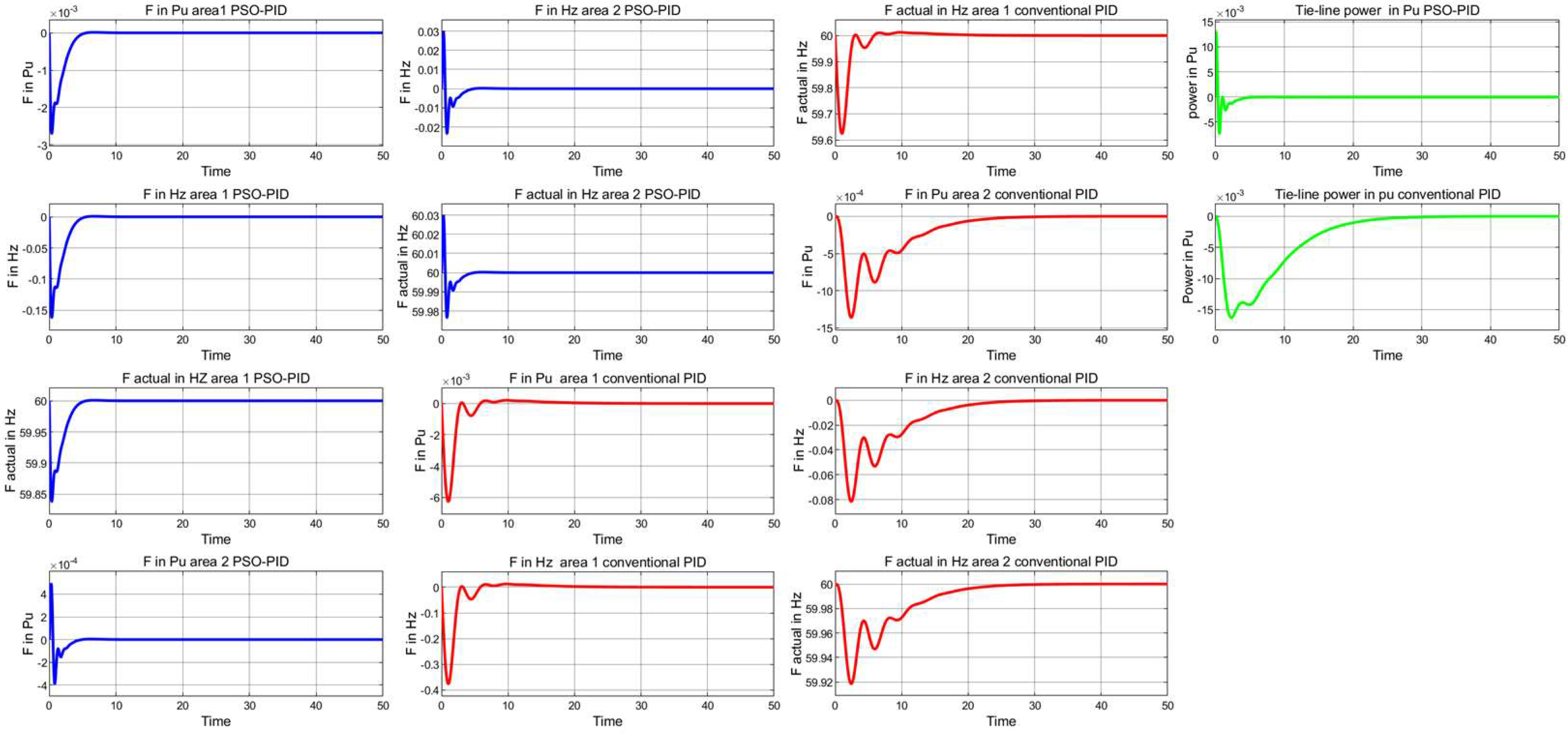
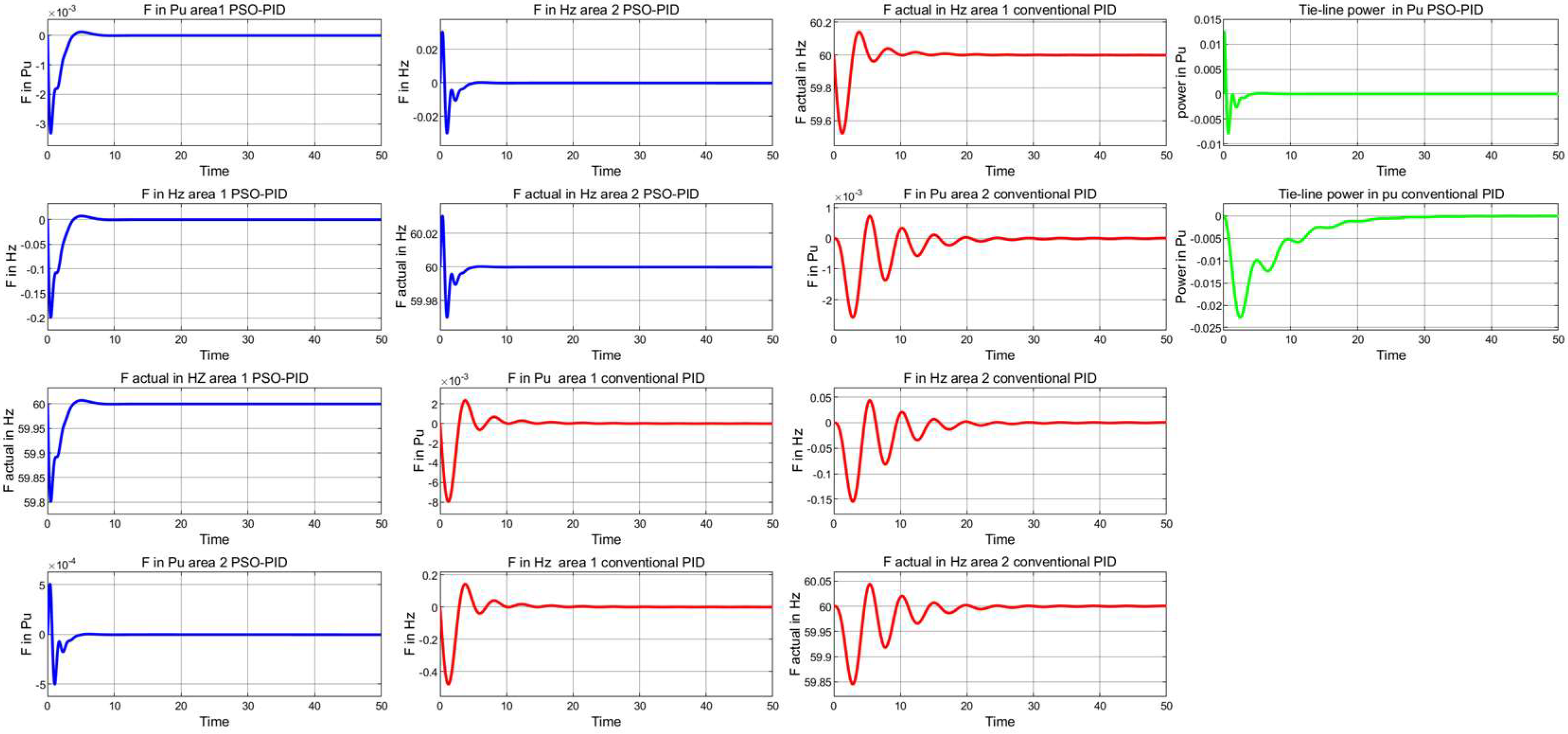
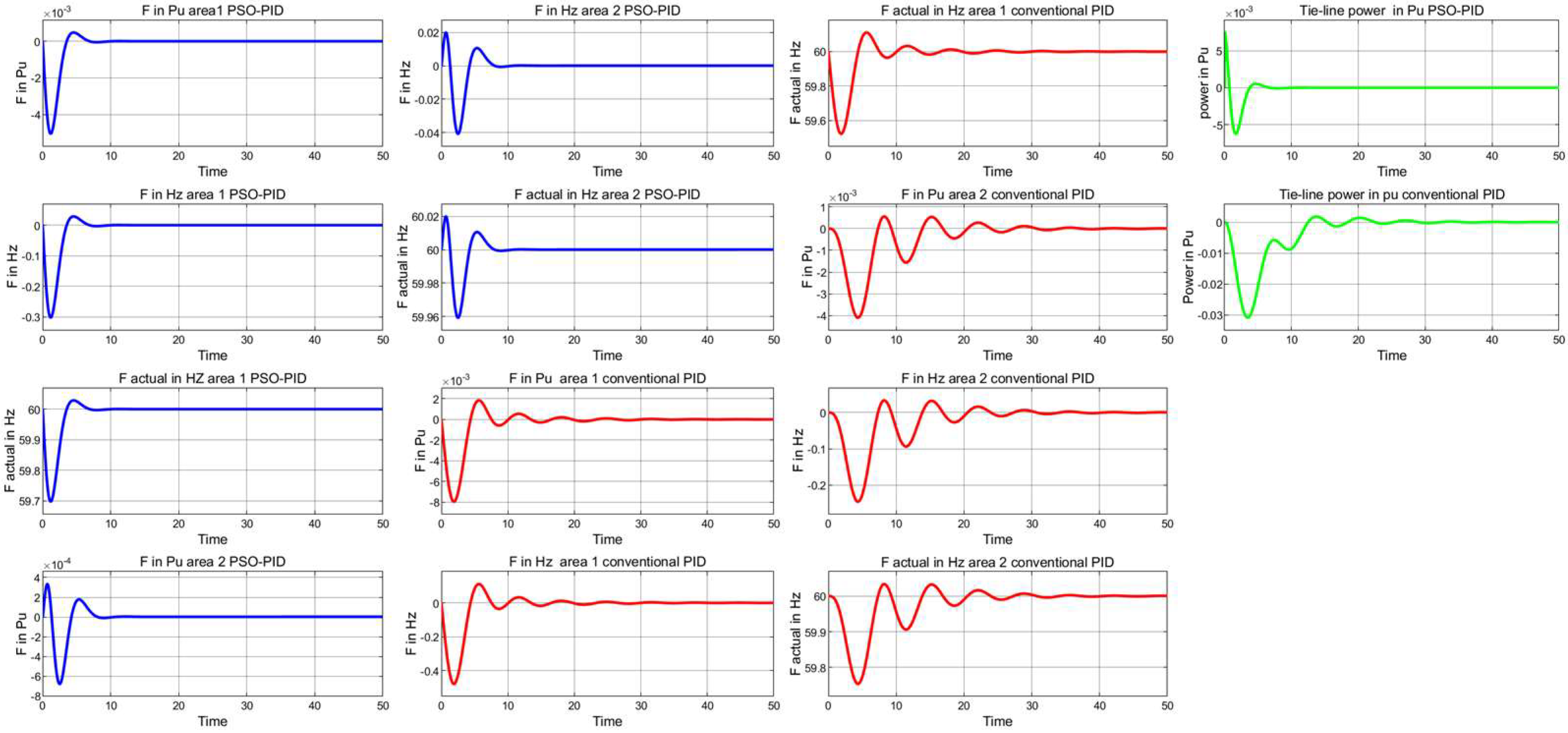
Just a single parameter is altered one time by +50%/−50% from its actual value in scenario 1 to scenario 12; in scenario 13, specification Tg, Tt, H, and R are altered by +50% in both areas, as shown in Table 8. At the same time, B and D were altered by a factor of −50%. Dynamic results of a double-area tie-line linked power network with PSO-PID controller and conventional PID controller under parametric ambiguity conditions are shown in Figure 20, Figure 21, Figure 22, Figure 23, Figure 24, Figure 25, Figure 26, Figure 27, Figure 28, Figure 29, Figure 30, Figure 31 and Figure 32. Table 9 shows the frequency response signal parameters of two-area tie-line IPS, while Ush represents undershoot, Osh overshoot, Psh pre-shoot, and H/L high and low frequency.

4.2.2. Load Variations (Case Study 2)

Three cases are taken into account against load variations, as shown in Table 10, to check the system’s flexibility.
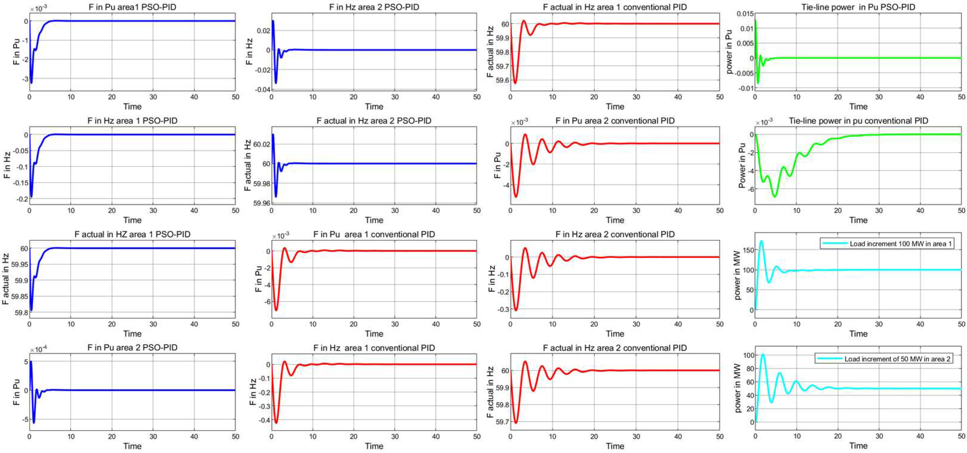
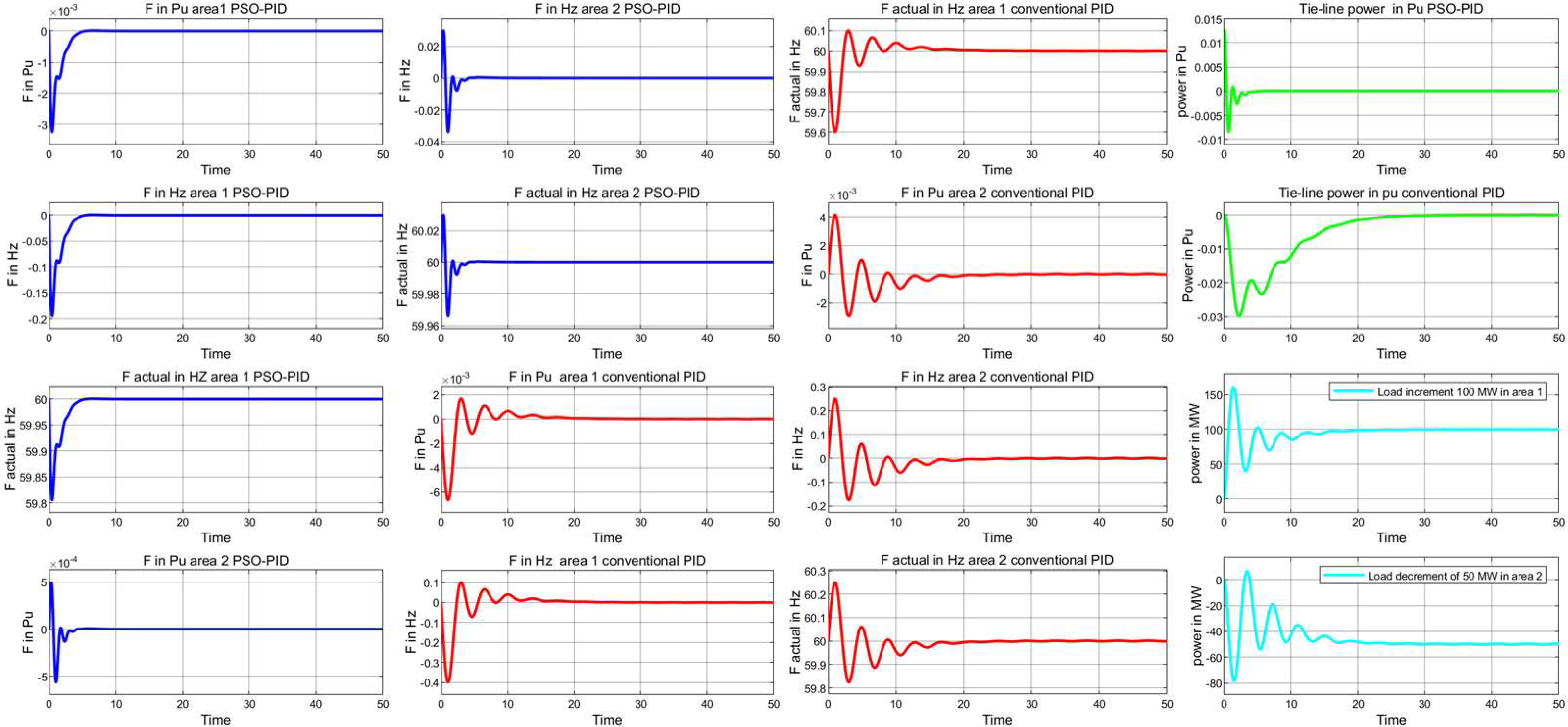
The results achieved for two-area tie-line IPS under load variations are shown in Figure 33, Figure 34 and Figure 35. Blue lines represent PSO-PID controller frequency responses in areas 1 and 2; red lines represent conventional PID controller frequency responses in areas 1 and 2; green lines represent tie-line power change between areas 1 and 2 with and without PSO-PID controller, while cyan color lines represent power shared by area 1 and 2. Table 11 shows the frequency responses of two-area tie-line IPS signal parameters under load variation for different cases.
The sensitivity investigation of the PSO-PID controller is executed in this proposed study by adjusting the system parameters of both networks in different cases throughout a range of ±50% from their nominal values and load variations in two-area tie-line IPS under different scenarios while maintaining the PSO-PID controller optimal parameters. Figure 16, Figure 17, Figure 18, Figure 20, Figure 21, Figure 22, Figure 23, Figure 24, Figure 25, Figure 26, Figure 27, Figure 28, Figure 29, Figure 30, Figure 31 and Figure 32 show the results achieved by adjusting the parameters in the proposed networks. The system parameters’ transient responses are almost equal to their nominal values, representing the robustness of the PSO-PID controller. Table 7 and Table 9 show the transient analysis based on undershoot, overshoot, pre-shoot, frequency, and fall time for various investigated scenarios under system parameter variations. Figure 33, Figure 34 and Figure 35 show the results achieved by changing load variations in two-area tie-line IPS. The load variation transient responses are almost equal to their variable loads. Table 11 shows the transient analysis based on undershoot, overshoot, pre-shoot frequency, and fall time for investigated scenarios under load variations. Finally, results demonstrate that, as compared to conventional PID controllers, PSO-PID controllers utilizing the ITAE cost function provide better results in terms of frequency responses under load changes and system parametric uncertainties for various examined cases.

5. Conclusions and Future Directions

5.1. Conclusions

This research presents an extensive performance evaluation of LFC for a one-area multi-source power network using a PID controller and dual-area tie-line interconnected power network. The PID controller’s parameters are optimized utilizing the PSO algorithm. The proposed networks with a PID controller have been tested by changing the system parameters ±50% for different cases in both networks and load variations in different cases for two-area tie-line IPS. Analyzing the simulation model results indicates clearly that the proposed method effectively reduced the frequency fluctuation and tie-line power deviations in the proposed networks. The frequency fluctuation associated with the one-area multi-source and the two-area tie-line IPS’s area 1 and area 2, respectively, are 59.98 Hz, 59.81 Hz, and 60 Hz and, in all other examined cases, are all less than the traditional PID controller. As a result, the utilized approach is superior to traditional PID controllers.

5.2. Future Directions

Currently, it is important to note the stability issue with connected power systems for renewable energy. Integrating and optimizing various renewable energy sources is a significant challenge for future studies. Furthermore, there is a lot of promise for resolving LFC-related issues in the development of revolutionary technologies like big data, cloud computing, and artificial intelligence. Below is a discussion of the present research difficulties and future directions.
  • Renewable energy: a number of previously unusable renewable energy sources have gradually been produced for power systems as a result of ongoing research into renewable energy. The power system’s connected renewable energy sources have a variety of power outputs, which adds uncertainty and complexity to the fluctuation of power generation. This poses difficulties for LFC power systems that are combined with RESs in terms of stabilization. Furthermore, integrating various renewable energy sources necessitates the employment of additional electrical equipment. LFC power systems will inevitably have obstacles related to ensuring device matching, efficient information transfer, and other matters.
  • Flexibility: Since renewable energy sources require significant penetration and networking requirements, an extremely flexible and secure integrated power system is required. A higher percentage of RESs can facilitate the transformation of the current energy production mix. This will increase the flexibility and dependability of multi-area power systems and lead to the creation of new intelligent algorithms for control, storage, and market strategies.

Author Contributions

Conceptualization, Z.Q.; supervision, W.Y.; writing—original draft preparation, Y.W., and P.M.G.; validation and formal analysis, Z.Q.; review—writing and editing. All authors have reviewed and approved the paper. All authors have read and agreed to the published version of the manuscript.

Funding

This research received no external funding.

Data Availability Statement

Data are available on request from the corresponding author.

Conflicts of Interest

The authors declare no conflict of interest.

Abbreviations

RESsRenewable energy sources
LFCLoad frequency control
IPSInterconnected power system
HCHill climbing
GAGenetic algorithm
ACOAnt colony optimization
PVPhotovoltaic
MARLMulti-agent reinforcement learning
FPAFlower pollination algorithm
FOFPIDFractional order fuzzy PID
ARAArtificial rabbits algorithm
MAPSMulti-area power systems
BESSOBald eagle sparrow search optimization
BBOBiogeography-based optimization
GBOGradient-based optimizer
TIDTilt integral derivative
AGCAutomatic generation control
RGovernor speed droop characteristics
HInertia constant
DCoefficient of damping
ACEArea control error
ΔPDPower change in the demand
BFactor of frequency bias
uInput for governor control
TgConstant governor time
ΔPgVariations in the governor’s valve position
TtConstant turbine time
WTGWind turbine generator
ΔPLChanges in load power
ΔPmChanges in mechanical power
ΔPtVariations in turbine output power
KP, KI & KDPID controller gains
ΔfChange in system frequency
ΔPtieTie-line power change
a12Constant

Appendix A

Table A1. Single-area thermal power system parameter values.
System ParameterParameter Value
Time Constant Turbine0.5 s
Time Constant Governor0.2 s
Generator Constant of Inertia5 s
Governor’s Speed Regulation0.05 per unit
Turbine power rating250 MW
Frequency60 hertz
Duty ratio D0.8

Appendix B

Table A2. Parameter values and electrical characteristics of wind, fuel cell, and solar units.
Electrical Characteristics of 1Soltech 1STH-215-P Solar Module
strings in parallel50
Modules connected in series for each string50
Maximum output power213.15 W
Voltage of open circuit36.3 V
Voltage at the point of maximum power29 V
Coefficient of temperature for open circuit voltage−0.36099
Each module’s cells60
Current on short circuit7.84 A
Current at the point of maximum power7.35 A
Temperature coefficient0.102
Specified temperature25 °C, 1000 (W/m2)
Ideality factor of diode0.98117
Resistance of shunt313.3991 Ohms
resistance in series0.39383 Ohms
PMSG wind turbine specifications
The mechanical output power nominally100 Kw
The electrical generator’s base power100 Kw/0.9
Maximum power (Pu of nominal mechanical power) at base wind speed0.85
Rotational base speed (Pu of the generator speed at base)1.2
PMSG’s stator phase resistance0.0485 ohms
Wind speed12 m/s
Fuel cell parameters
Function 1: 1.36908036 atomic mass units60,000 × 8.3145 × (273 + 95) × 400 × u (1)/(2 × 96,485 × (3 × 101,325) × 0.919 × 0.995)
Function 2: 5.89420573 atomic mass units60,000 × 8.3145 × (273 + 95) × 400 × u (1)/(4 × 96,485 × (3 × 101,325) × 0.5057 × 0.21)
Stack power (Watts)25,200
Fuel cell resistance (ohms)4.2142
Nerst voltage of one cell (V)0.9835
Exchange current (A)0.27591
Exchange coefficient0.78812
System temperature (K)1133
Fuel supply pressure (bar)1.2
Air supply pressure (bar)1

Appendix C

Table A3. PSO approach operators for a single-area multi-source power network.
Operator Operator Value
Solverode23s (stiff/Mod.Rosenbrock)
Fitness functionITAE
Number of variables3
Number of iterations100
Number of particles15
Limit0.1000
c1= c22
wmax1
wmin0.1

Appendix D

Table A4. The two-area tie-line linked the power system’s parameters.
System ParametersArea 1Area 2
Speed regulation R0.050.0625
Duty ratio D0.60.9
Inertia constant H54
Base power1000 MVA1000 MVA
Gt0.2 s0.3 s
Tt0.5 s0.6 s

Appendix E

Table A5. Operators of PSO approach for two-area tie-line interconnected power system.
Operator Operator Value
Solverode23s (stiff/Mod.Rosenbrock)
Fitness functionITAE
Number of variables9
Number of iterations100
Number of particles15
Limit0.1000
c1= c22
wmax1
wmin0.1

References

  1. Arya, Y.; Dahiya, P.; Çelik, E.; Sharma, G.; Gözde, H.; Nasiruddin, I. AGC performance amelioration in multi-area interconnected thermal and thermal-hydro-gas power systems using a novel controller. Eng. Sci. Technol. Int. J. 2021, 24, 384–396. [Google Scholar] [CrossRef]
  2. Elkasem, A.H.; Khamies, M.; Hassan, M.H.; Agwa, A.M.; Kamel, S. Optimal design of TD-TI controller for LFC considering renewables penetration by an improved chaos game optimizer. Fractal Fract. 2022, 6, 220. [Google Scholar] [CrossRef]
  3. Ameli, A.; Hooshyar, A.; El-Saadany, E.F.; Youssef, A.M. Attack detection and identification for automatic generation control systems. IEEE Trans. Power Syst. 2018, 33, 4760–4774. [Google Scholar] [CrossRef]
  4. Mohammadikia, R.; Aliasghary, M. A fractional order fuzzy PID for load frequency control of four-area interconnected power system using biogeography-based optimization. Int. Trans. Electr. Energy Syst. 2019, 29, e2735. [Google Scholar] [CrossRef]
  5. Ali, T.; Malik, S.A.; Hameed, I.A.; Daraz, A.; Mujlid, H.; Azar, A.T. Load frequency control and automatic voltage regulation in a multi-area interconnected power system using nature-inspired computation-based control methodology. Sustainability 2022, 14, 12162. [Google Scholar] [CrossRef]
  6. Ali, T.; Malik, S.A.; Daraz, A.; Aslam, S.; Alkhalifah, T. Dandelion optimizer-based combined automatic voltage regulation and load frequency control in a multi-area, multi-source interconnected power system with nonlinearities. Energies 2022, 15, 8499. [Google Scholar] [CrossRef]
  7. Jagatheesan, K.; Anand, B.; Samanta, S.; Dey, N.; Ashour, A.S.; Balas, V.E. Particle swarm optimisation-based parameters optimisation of PID controller for load frequency control of multi-area reheat thermal power systems. Int. J. Adv. Intell. Paradig. 2017, 9, 464–489. [Google Scholar] [CrossRef]
  8. Dhanasekaran, B.; Siddhan, S.; Kaliannan, J. Ant colony optimization technique tuned controller for frequency regulation of single area nuclear power generating system. Microprocess. Microsyst. 2020, 73, 102953. [Google Scholar] [CrossRef]
  9. El-Sehiemy, R.; Shaheen, A.; Ginidi, A.; Al-Gahtani, S.F. Fractional. Proportional-Integral-Derivative Controller Based-Artificial Rabbits Algorithm for Load Frequency Control in Multi-Area Power Systems. Fractal Fract. 2023, 7, 97. [Google Scholar] [CrossRef]
  10. Abou El-Ela, A.A.; El-Sehiemy, R.A.; Shaheen, A.M.; Diab, A.E.-G. Design of cascaded controller based on coyote optimizer for load frequency control in multi-area power systems with renewable sources. Control Eng. Pract. 2022, 121, 105058. [Google Scholar] [CrossRef]
  11. Alayi, R.; Zishan, F.; Seyednouri, S.R.; Kumar, R.; Ahmadi, M.H.; Sharifpur, M. Optimal load frequency control of island microgrids via a PID controller in the presence of wind turbine and PV. Sustainability 2021, 13, 10728. [Google Scholar] [CrossRef]
  12. Vedik, B.; Kumar, R.; Deshmukh, R.; Verma, S.; Shiva, C.K. Renewable energy-based load frequency stabilization of interconnected power systems using quasi-oppositional dragonfly algorithm. J. Control Autom. Electr. Syst. 2021, 32, 227–243. [Google Scholar] [CrossRef]
  13. Mohanty, B.; Panda, S.; Hota, P. Controller parameters tuning of differential evolution algorithm and its application to load frequency control of multi-source power system. Int. J. Electr. Power Energy Syst. 2014, 54, 77–85. [Google Scholar] [CrossRef]
  14. Panwar, A.; Sharma, G.; Bansal, R.C. Optimal AGC design for a hybrid power system using hybrid bacteria foraging optimization algorithm. Electr. Power Compon. Syst. 2019, 47, 955–965. [Google Scholar] [CrossRef]
  15. Bharti, K.K.; Singh, V.P.; Singh, S. PSO-based: MARL approach for frequency regulation of multi-area power system. J. Electr. Eng. Technol. 2020, 15, 1529–1539. [Google Scholar] [CrossRef]
  16. Jagatheesan, K.; Anand, B.; Samanta, S.; Dey, N.; Santhi, V.; Ashour, A.S.; Balas, V.E. Application of flower pollination algorithm in load frequency control of multi-area interconnected power system with nonlinearity. Neural Comput. Appl. 2017, 28, 475–488. [Google Scholar] [CrossRef]
  17. Kumarakrishnan, V.; Vijayakumar, G.; Boopathi, D.; Jagatheesan, K.; Saravanan, S.; Anand, B. Optimized PSO technique based PID controller for load frequency control of single area power system. Solid State Technol. 2020, 63, 7979–7990. [Google Scholar]
  18. Gupta, D.K.; Jha, A.V.; Appasani, B.; Srinivasulu, A.; Bizon, N.; Thounthong, P. Load frequency control using hybrid intelligent optimization technique for multi-source power systems. Energies 2021, 14, 1581. [Google Scholar] [CrossRef]
  19. Ram Babu, N.; Bhagat, S.K.; Saikia, L.C.; Chiranjeevi, T.; Devarapalli, R.; García Márquez, F.P. A comprehensive review of recent strategies on automatic generation control/load frequency control in power systems. Arch. Comput. Methods Eng. 2023, 30, 543–572. [Google Scholar] [CrossRef]
  20. Naderipour, A.; Abdul-Malek, Z.; Davoodkhani, I.F.; Kamyab, H.; Ali, R.R. Load-frequency control in an islanded microgrid PV/WT/FC/ESS using an optimal self-tuning fractional-order fuzzy controller. Environ. Sci. Pollut. Res. 2023, 30, 71677–71688. [Google Scholar] [CrossRef]
  21. Hu, C.; Bi, L.; Piao, Z.; Wen, C.; Hou, L. Coordinative optimization control of microgrid based on model predictive control. Int. J. Ambient. Comput. Intell. 2018, 9, 57–75. [Google Scholar] [CrossRef]
  22. Bhattacharya, H.; Chattopadhyay, S.; Chattopadhyay, M.; Banerjee, A. Storage and bandwidth optimized reliable distributed data allocation algorithm. Int. J. Ambient. Comput. Intell. 2019, 10, 78–95. [Google Scholar] [CrossRef]
  23. Choudhary, R.; Rai, J.; Arya, Y. Automatic generation control for single area power system using GNA tuned PID controller. In Journal of Physics: Conference Series; IOP Publishing: Bristol, UK, 2020; Volume 1478, p. 012011. [Google Scholar]
  24. Raj, T.D.; Kumar, C.; Kotsampopoulos, P.; Fayek, H.H. Load Frequency Control in Two-Area Multi-Source Power System Using Bald Eagle-Sparrow Search Optimization Tuned PID Controller. Energies 2023, 16, 2014. [Google Scholar] [CrossRef]
  25. Dhanasekaran, B.; Kaliannan, J.; Baskaran, A.; Dey, N.; Tavares, J.M.R. Load Frequency Control Assessment of a PSO-PID Controller for a Standalone Multi-Source Power System. Technologies 2023, 11, 22. [Google Scholar] [CrossRef]
  26. Ali, T.; Malik, S.A.; Daraz, A.; Adeel, M.; Aslam, S.; Herodotou, H. Load frequency control and automatic voltage regulation in four-area interconnected power systems using a gradient-based optimizer. Energies 2023, 16, 2086. [Google Scholar] [CrossRef]
  27. Debnath, M.K.; Agrawal, R.; Tripathy, S.R.; Choudhury, S. Artificial neural network tuned PID controller for LFC investigation including distributed generation. Int. J. Numer. Model. Electron. Netw. Devices Fields 2020, 33, e2740. [Google Scholar] [CrossRef]
  28. Kumarakrishnan, V.; Vijayakumar, G.; Jagatheesan, K.; Boopathi, D.; Anand, B.; Kanendra Naidu, V. PSO optimum design-PID controller for frequency management of single area multi-source power generating system. In Contemporary Issues in Communication, Cloud and Big Data Analytics; Springer: Berlin/Heidelberg, Germany, 2022; pp. 373–383. [Google Scholar]
  29. Wang, Z.; Liu, Y.; Yang, Z.; Yang, W. Load frequency control of multi-region interconnected power systems with wind power and electric vehicles based on sliding mode control. Energies 2021, 14, 2288. [Google Scholar] [CrossRef]
  30. Eisa, S.A. Modeling dynamics and control of type-3 DFIG wind turbines: Stability, Q Droop function, control limits and extreme scenarios simulation. Electr. Power Syst. Res. 2019, 166, 29–42. [Google Scholar] [CrossRef]
  31. Eisa, S.A.; Wedeward, K.; Stone, W. Wind turbines control system: Nonlinear modeling, simulation, two and three time scale approximations, and data validation. Int. J. Dyn. Control. 2018, 6, 1776–1798. [Google Scholar] [CrossRef]
  32. Eisa, S.A. Nonlinear modeling, analysis and simulation of wind turbine control system with and without pitch control as in industry. In Advanced Control and Optimization Paradigms for Wind Energy Systems. Power Systems; Springer: Berlin/Heidelberg, Germany, 2019; pp. 1–40. [Google Scholar]
  33. Sobhy, M.A.; Abdelaziz, A.Y.; Hasanien, H.M.; Ezzat, M. Marine predators algorithm for load frequency control of modern interconnected power systems including renewable energy sources and energy storage units. Ain Shams Eng. J. 2021, 12, 3843–3857. [Google Scholar] [CrossRef]
  34. Khooban, M.H.; Gheisarnejad, M. A novel deep reinforcement learning controller based type-II fuzzy system: Frequency regulation in microgrids. IEEE Trans. Emerg. Top. Comput. Intell. 2020, 5, 689–699. [Google Scholar] [CrossRef]
  35. Ginidi, A.; Ghoneim, S.M.; Elsayed, A.; El-Sehiemy, R.; Shaheen, A.; El-Fergany, A. Gorilla troops optimizer for electrically based single and double-diode models of solar photovoltaic systems. Sustainability 2021, 13, 9459. [Google Scholar] [CrossRef]
  36. Kouba, N.E.Y.; Menaa, M.; Hasni, M.; Boudour, M. LFC enhancement concerning large wind power integration using new optimised PID controller and RFBs. IET Gener. Transm. Distrib. 2016, 10, 4065–4077. [Google Scholar] [CrossRef]
Figure 1. An illustrative representation of the speed governor system.
Energies 17 00517 g001
Figure 2. Turbine model transfer function.
Energies 17 00517 g002
Figure 3. Mathematical model schematic block diagram for load.
Energies 17 00517 g003
Figure 4. Isolated single-area thermal power system’s block diagram.
Energies 17 00517 g004
Figure 5. Block schematic of a PMSG wind power system featuring an MPPT-powered DC-DC boost converter.
Energies 17 00517 g005
Figure 6. P & O MPPT algorithm for PMSG wind turbine model.
Energies 17 00517 g006
Figure 7. Circuit model for a single-diode photovoltaic module.
Energies 17 00517 g007
Figure 8. Equivalent circuit two-diode PV system.
Energies 17 00517 g008
Figure 9. Block diagram of fuzzy-based MPPT solar PV model.
Energies 17 00517 g009
Figure 10. MPPT technique using fuzzy logic for solar PV model.
Energies 17 00517 g010
Figure 11. Block diagram for a two-area connected power system.
Energies 17 00517 g011
Figure 12. Basic design of a PID controller.
Energies 17 00517 g012
Figure 13. Simulink model of one-area multi-source power network.
Energies 17 00517 g013
Figure 14. Two-area tie-line interlinked power system Simulink model.
Energies 17 00517 g014
Figure 15. Diagram illustrating the PSO technique for PID controller adjusting parameters.
Energies 17 00517 g015
Figure 16. Frequency responses of one-area power network with multiple sources.
Energies 17 00517 g016
Figure 17. Single-area multi-source frequency responses in scenario 1.
Energies 17 00517 g017
Figure 18. Single-area multi-source frequency responses in scenario 2.
Energies 17 00517 g018
Figure 19. Transient frequency responses of two-area tie-line IPS.
Energies 17 00517 g019
Figure 20. Frequency responses of two-area tie-line IPS in case 1.
Energies 17 00517 g020
Figure 21. Frequency responses of two-area tie-line IPS in case 2.
Energies 17 00517 g021
Figure 22. Frequency responses of two-area tie-line IPS in case 3.
Energies 17 00517 g022
Figure 23. Frequency responses of two-area tie-line IPS in case 4.
Energies 17 00517 g023
Figure 24. Frequency responses of two-area tie-line IPS in case 5.
Energies 17 00517 g024
Figure 25. Frequency responses of two-area tie-line IPS in case 6.
Energies 17 00517 g025
Figure 26. Frequency responses of two-area tie-line IPS in case 7.
Energies 17 00517 g026
Figure 27. Frequency responses of two-area tie-line IPS in case 8.
Energies 17 00517 g027
Figure 28. Frequency responses of two-area tie-line IPS in case 9.
Energies 17 00517 g028
Figure 29. Frequency responses of two-area tie-line IPS in case 10.
Energies 17 00517 g029
Figure 30. Frequency responses of two-area tie-line IPS in case 11.
Energies 17 00517 g030
Figure 31. Frequency responses of two-area tie-line IPS in case 12.
Energies 17 00517 g031
Figure 32. Frequency responses of two-area tie-line IPS in case 13.
Energies 17 00517 g032
Figure 33. Two-area tie-line IPS frequency responses in scenario 1.
Energies 17 00517 g033
Figure 34. Two-area tie-line IPS frequency responses in scenario 2.
Energies 17 00517 g034
Figure 35. Two-area tie-line IPS frequency responses in scenario 3.
Energies 17 00517 g035
Table 1. Review of the literature that has been studied.
Technique for Optimization/Secondary ControllerPower SourceWorkReference
PSO/PIDGenerating source thermalCompared outcomes with GA and HC [7]
ARA/PIDTwo-area non-reheat thermal systemsCompared results with PSO, DE, JAYA optimizer[9]
GA/PIDSource of thermal generationPerformance of PI and PID with and without GRC[23]
BESSO/PIDHydro, Gas, and thermalAnalyzed the controller efficacy and compared the findings with conventional PID controller[24]
PSO/PIDThermal, Hydro, and GasResults compared with DE and GA[25]
DE/PIDThermal, Hydro, and GasAnalyzed controller efficiency utilizing I, PI, and PID[13]
HBFOA/PIDThermal and PVPSO and BFO results examined[14]
GBO/PIDGas, Thermal, Hydro, Solar, and WindResults compared with GBO-I-PD, GBO-TID, and GBO-I-P[26]
ANN/PIDDistributed power sources (WTG, DEG, AE, FC)The superiority of the proposed approach was achieved by applying the Grasshopper optimization algorithm.[27]
PSO/PIDPV, Nuclear, Hydro, Gas, and ThermalComparison of PSO-PID and ordinary PID controller outcomes[17]
PSO/PIDThermal, Solar, and WindPerformance comparison of standard I, PI, and PID controllers[28]
Table 2. The fuzzy rule solar PV MPPT.
ΔVpv × (o/p)ΔVpv(i/p)
ΔPpv(i/p) NBNSZEPSPB
NBPSPBNBNBNS
NSPSPSNSNSNS
ZEZEZEZEZEZE
PSNSNSPSPSPS
PBNSNBPBPBPS
Table 3. The fuzzy rule ranges, membership functions, and their types.
Input/OutputNo. of Membership FunctionRange of Membership FunctionType of Membership Function
Input 15 membership functionsRange (−8.5 to 8.5)Triangular mf
Input 25 membership functionsRange (−1.6 to 1.6)Triangular mf
Output5 membership functionsRange (−1.6 to 1.6)Triangular mf
Table 4. PID controller gain values for single-area multi-source power network.
PID Gain ParametersKPKIKD
Conventional-PID103050
PSO-PID211
Table 5. PSO-PID gain parameters of a two-area tie-line interconnected power system.
Area 1 Area 2 Tie-Line
PSO-PIDPIDPIDPID
0.807440.78184−0.331670.39749−0.604380−0.9389180.488144.40 × 10−05−0.040155
Table 6. The two scenarios’ respective parameter variation ranges.
ScenariosSpecificationsValue at NominalRange of VariationNew Value after Variation
Scenario 1Tg0.2+50%0.3
H5+50%10
D0.8−50%0.4
R0.05−50%0.025
Scenario 2Tg0.2−50%0.1
H5−50%2.5
D0.8+50%1.2
R0.05+50%0.075
Table 7. Frequency responses of single-area multi-source signal parameters.
Frequency Responses
ControllerUndershoot
%
Overshoot
%
Settling Time sFall Time
ms
ErrorPre-Shoot %High/Low
Hz
Conventional PID0.5051.5766327.3390.27970.24160/59.65
PSO-PID0.505−0.5050.007516.9620.0008−0.1160/59.98
Scenario 1
PSO-PID0.532−0.5320.008516.8690.02110.03360/59.99
Conventional PID0.5051.7353.3370.1980.25250.29160/59.80
Scenario 2
PSO-PID0.505−0.5050.007914.7770.00050.03960/59.97
Conventional PID42.1430.3254.2128.5020.30040.64060/59.67
Table 8. Investigated cases of system parameter changes.
Case NumberParametersNominal ValuesVariation RangeNew Values
Area 1Area 2Area 1Area 2
1H54+50%7.56
2H54−50%2.52
3Tt0.50.6+50%0.750.9
4Tt0.50.6−50%0.250.3
5B20.616.9+50%30.925.35
6B20.616.9−50%10.38.45
7D0.60.9+50%0.91.35
8D0.60.9−50%0.30.45
9Tg0.20.3+50%0.30.45
10Tg0.20.3−50%0.10.15
11R0.050.0625+50%0.0750.0937
12R0.050.0625−50%0.0250.0312
13B20.616.9−50%10.38.45
H54+50%7.56
R0.050.0625+50%0.0750.0937
D0.60.9−50%0.30.45
Tt0.50.6+50%0.750.9
Tg0.20.3+50%0.30.45
Table 9. Frequency responses of two-area tie-line IPS signal parameters.
Frequency Responses Area 1Frequency Responses Area 2Tie-Line Power (Pu) Response
ControllerUsh
%
Osh
%
Psh %H/L
Hz
Ush
%
Osh
%
Psh %H/L
Hz
Ush
%
Osh
%
Psh %Fall Time ms
PSO-PID0.501.050.1160/59.81137.04−5.3174.5660/6068.64−7.400.84207.96
Conventional PID0.571.82−0.1160/59.5950.7592.900.1160/59.9436.302.160.61895.73
Case no 1
PSO-PID7.060.41−0.1060/59.850.980.2095.0960/59.9855.461.190.78282.64
Conventional PID0.541.760.2360/59.6691.341.190.9660/59.9536.300.840.681147
Case no 2
PSO-PID0.500.470.2260/59.7984.47−9.47121.5860/59.9974.56−9.570.87190.03
Conventional PID0.581.92−0.0860/59.579.441.102.0960/59.9214.3618.650.48995.140
Case 3
PSO-PID0.500.420.1160/59.770.89−0.8977.6760/59.9668.64−4.150.84254.17
Conventional PID0.681.360.6160/59.5492.47−10.1368.8560/59.950.500.82−0.011328
Case 4
PSO-PID25.9421.43−0.0460/59.88163.21−163.21509.8960/6074.561.540.87146.19
Conventional PID1.790.500.5060/59.650.501.280.5060/59.930.501.700.501272
Case 5
PSO-PID95−6.870.6860/59.92172.88−17.2697.6260/6068.640.0868.64173.81
Conventional PID0.671.020.0960/59.6094.88−7.7159.2060/59.9695.09−4.110.98652.40
Case 6
PSO-PID0.501.130.5060/59.730.861.7471.5560/59.9477.67−0.940.89258.51
Conventional PID0.501.110.5060/59.5884.25−5.330.9260/59.942.718.20−0.0731309
Case 7
PSO-PID0.500.980.1560/59.81138.28−6.3966.7960/6068.64−8.450.84206.75
Conventional PID0.561.780.2360/59.600.501.120.1660/59.9132.661.850.61917.64
Case 8
PSO-PID0.501.120.0760/59.80135.47−0.1482.3560/59.9968.64−6.320.84209.14
Conventional PID0.581.88−0.4960/59.580.511.900.0760/59.9019.8816.660.521010
Case 9
PSO-PID0.500.480.1360/59.7893.30−28.50143.2860/59.9974.56−15.360.87243.408
Conventional PID0.641.09−0.4760/59.560.641.89−0.5960/59.8919.8831.310.331032
Case 10
PSO-PID42.14−7.40−0.0260/59.89172.68−1.07153.1060/6057.93−9.670.79161.879
Conventional PID0.521.750.2760/59.6357.9335.930.7960/59.9514.362.720.571071
Case 11
PSO-PID85.75−2.87−0.1960/59.8997.240.0940.2260/6063.11−3.980.82214.27
Conventional PID0.641.75−0.5660/59.5346.560.2525.8760/59.920.501.890.461421
Case 12
PSO-PID25.940.560.6360/59.850.831.9065.8360/59.9684.25−17.730.92192.19
Conventional PID0.601.170.3960/59.6944.4012.013.6960/59.970.5216.90−0.293132
Case 13
PSO-PID1.660.98−0.1460/59.700.74−0.7448.5060/59.9684.251.360.92476.575
Conventional PID0.611.06−0.3460/59.530.571.180.5460/59.760.530.74−0.102013
Table 10. Load variation cases for two-area tie-line IPS.
Case NoArea 1Area 2
1100 MW increment-
2100 MW increment50 MW increment
3100 MW increment50 MW decrement
Table 11. Frequency responses of two-area tie-line IPS signal parameters for load variations.
Frequency Responses Area 1Frequency Responses Area 2Tie-Line Power (Pu) Response
ControllerUsh
%
Osh
%
Psh %H/L
Hz
Ush
%
Osh
%
Psh %H/L
Hz
Ush
%
Osh
%
Psh %Fall Time ms
Case no 1
PSO-PID0.501.050.1160/59.81137.04−5.3174.5660/6068.64−7.400.84207.96
Conventional PID0.571.82−0.1160/59.5950.7592.900.1160/59.9436.302.160.61895.73
Case no 2
PSO-PID0.501.050.1160/59.81137.04−5.3174.5660/6068.64−7.400.84207.96
Conventional PID0.571.82−0.1160/59.8050.7592.900.1160/59.9736.302.160.61895.73
Case 3
PSO-PID0.501.050.1160/59.81137.04−5.3174.5660/6068.64−7.400.84207.96
Conventional PID14.3618.690.5760.2/600.712.3750.7560/60.032.1636.300.61897.22
Disclaimer/Publisher’s Note: The statements, opinions and data contained in all publications are solely those of the individual author(s) and contributor(s) and not of MDPI and/or the editor(s). MDPI and/or the editor(s) disclaim responsibility for any injury to people or property resulting from any ideas, methods, instructions or products referred to in the content.