Article

A Novel Approach to Using Dual-Field Excited Synchronous Generators as Wind Power Generators

1
Department of Electrical Engineering, Visvesvaraya National Institute of Technology, Nagpur 440010, India
2
Department of Power System and Control, Faculty of Electrical Engineering, Silesian University of Technology, 44-100 Gliwice, Poland
*
Author to whom correspondence should be addressed.
Energies 2024, 17(2), 456; https://doi.org/10.3390/en17020456
Submission received: 4 December 2023 / Revised: 23 December 2023 / Accepted: 29 December 2023 / Published: 17 January 2024
(This article belongs to the Section F1: Electrical Power System)

Abstract

:
Integrating wind power generators, whose frequency varies in a wide range due to varying wind speeds, into a grid is a formidable problem. At present, the use of permanent magnet synchronous generators (PMSG) and doubly fed induction generators (DFIG) as wind generators with suitable control is the best possible solution. However, a dual-field excited synchronous generator (DESG), which has two windings on the rotor, can also be used for the same purpose with appropriate control. A new control strategy, which essentially employs the d-axis and q-axis components of the alternator terminal voltage, is suggested here. This strategy essentially results in exciting the two field windings with a slip frequency. This eventually holds the stator frequency constant, irrespective of the rotor speed of the wind generator. The difference between the required frequency and the natural frequency, analogous to the rotor speed of the wind power generator, is the slip frequency. The ring modulator automatically adjusts the slip frequency depending on the actual speed of the generator’s rotor. This paper uses the ANSYS MAXWELL 2022 R1 software to design a DESG and uses a ring modulator as the control function generator for feedback with ANSYS TWIN BUILDER 2022 R1. Simulations are carried out using transient–transient co-simulation by combining both of these software tools for cases of both a constant-speed input and of a variable-speed input to the rotor of the machine. Moreover, a mathematical model of the DESG as a wind generator with the proposed controlled strategy is used to perform the stability analysis of a nine-bus three-machine system, and the results are compared with those of conventional wind generators.

1. Introduction

Utilizing clean and renewable energy sources for power generation has become a necessity to keep up with the remarkable growth of the industrial sector and societal demands. Hydro-power, wind power, and solar power are the three most dependable renewable energy sources. One of the most significant sources of renewable energy is provided by wind power generation systems because of their sustainability and lack of contamination [1,2,3]. The various types of wind turbine generators mentioned in the literature are as follows: self-excited induction generators (SEIGs), doubly fed induction generators (DFIGs), field-excited synchronous generators (FESGs), permanent magnet synchronous generators (PMSGs), and surface-mounted permanent magnet generators (SMPMs). Wind power generators such as SEIGs and FESGs use gearboxes, whereas DFIGs, PMSGs, and SMPMs almost eliminate the need for a gearbox, making them direct drive machines [4]. A variable-speed, constant-frequency generator is often used in wind energy conversion technologies because of the intermittent nature of wind. Recently, the DFIG and PMSG have become the most commercially successful variable-speed wind power generators.
The DFIG is recognized as the most used generator in wind energy systems because of its numerous advantages, including the ability to operate at variable speeds over a vast range, the independent control of reactive and active power, and low-rated power electronic converters that lead to cost-effectiveness [5,6,7]. Moreover, DFIGs have setbacks like losses due to slip rings, a need for regular maintenance, and being vulnerable to disturbances in the grid [8]. The PMSG’s self-excitation and the elimination of the gearbox make it lighter than the DFIG, which minimizes losses and boosts the system’s efficiency [9,10]. PMSGs require high-power-rating converters as they connect to the grid directly through a back-to-back converter. The expensive price of permanent magnets and their ageing impacts are drawbacks of PMSGs.
Recent advancements in electrical machines have introduced various machines as potential wind generators, such as brushless DFIGs [11,12] and various types of stator-PM machines [13,14,15]. However, it has been mentioned that a dual-field excited synchronous generator (DESG) can also be used as a variable-speed, constant-frequency wind power generator [16,17] with appropriate control. In such cases, the DESG requires two-phase slip frequency excitation. The operation of DESGs is almost identical to the operation of DFIGs, with the exception of having two windings on the rotor that are both mechanically and electrically 90° apart.
In the literature, DESGs have been presented as significantly better generators than conventional synchronous generators (CSGs) in strengthening the system’s reliability and stability, and for their independent control of the voltage or reactive power and torque or active power [18,19,20] with DC excitation. The design and finite element analysis of DESGs with non-salient pole core rotors [21] or slot core rotors [22,23] with different excitation techniques also show that the performance of DESGs is better than that of the CSG. It has been proposed that the DESG can also be used in electric vehicles [24] with the help of a variable voltage and a variable frequency converter to overcome the present issue of the unequal diameter of wheels in vehicles. In addition, [25] presents a different approach to enabling the DESG work with a slip frequency by modifying the rotor winding structure, arranging the two winding groups in such a way that they look like a staircase when moving from one slot to the next.
The control of DESGs based on rotor active power was proposed in [26], showing improved efficiency [27]. Different computer-based control techniques have been proposed for the regulation of the terminal voltage and frequency [28,29]. By introducing the field current as feedback into the excitation system, the behavior and control of the DESG, which has the advantages of both synchronous machines and induction machines, are presented in [30] with the help of experimental results and phasor diagrams. The design and magnetic field distribution analysis of DESGs is presented in [31]. The proposed control technique in [26] mainly focuses on the extraction of the maximum active power and the use of simple diode rectifiers to reduce costs by eliminating back-to-back converters in the system. The extraction of the maximum power and reactive power control is achieved by controlling the field currents of the DESG in [32,33]. The stability of the power system is improved by modifying the rotor-side converter controller of the DFIG with the use of the post-disturbance terminal bus frequency of the DFIG in [34], and the same is achieved in [35] by supplying the reactive power through the grid-side converter during the fault period, with the adjustment of the real power supply.
This paper describes a two-dimensional (2D) MAXWELL design of a DESG and a simple nonlinear control technique that uses both the d-axis and q-axis components of the alternator terminal voltage. This strategy results in slip frequency excitation (sine and cosine components) of the two field windings, which keeps the stator frequency constant, irrespective of the speed of the wind generator. The difference between the targeted stator frequency and the natural frequency, which relates to the generator speed, determines the slip frequency. The ring modulator automatically adjusts the slip frequency based on the rotor speed. The inherent operational flexibility of a three-phase synchronous machine with two field windings is the control of both the magnitude and space position of the resultant rotor or field magneto-motive force (MMF) without physically changing the angular position of the rotor, which is the chief reason for the superior performance of DESGs compared to CSGs. Results of the DESG with the proposed control method are presented when the DESG is connected to a constant impedance load as well as in a no-load condition. The DESG operated with constant-speed and variable-speed input is presented in this paper. This study also presents the fault analysis of a nine-bus, three-machine WSCC system that is linked to a wind generator (DESG). It compares the critical clearing time (CCT) of the DFIG to that of the DESG.
The organization of the remainder of the paper is as follows. Section 2 presents the modeling of the DESG using the ANSYS 2022 R1 software. A new and simple control strategy is presented in Section 3 to obtain the desired slip frequency, and Section 4 discusses the results and analysis of the system under study, followed by the conclusions in the final Section 5.

2. Modeling of DESG

The mathematical and Maxwell’s finite element method models of the DESG are presented in this section.

2.1. Mathematical Model
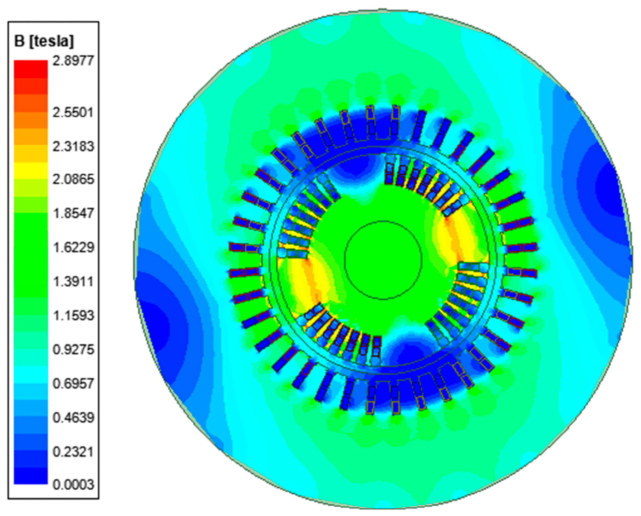
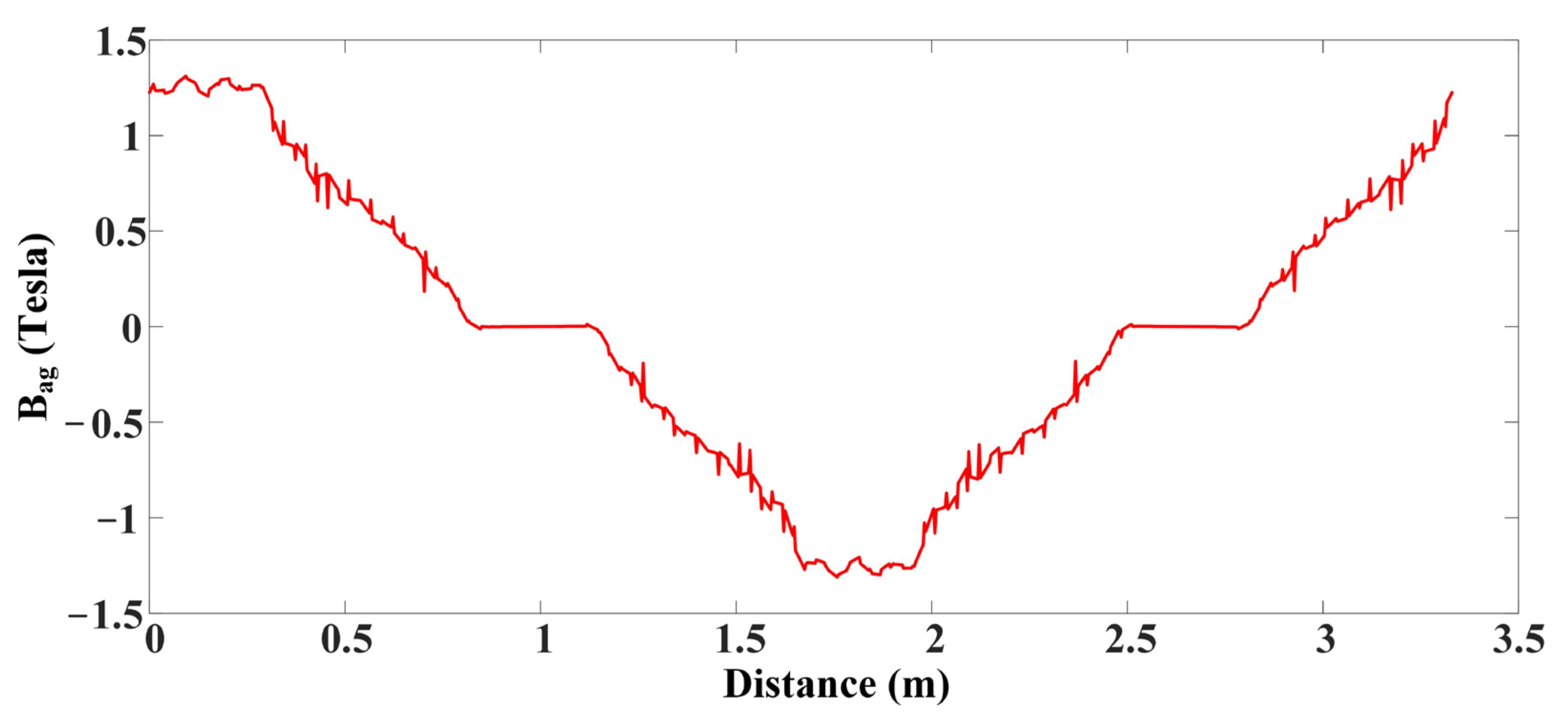
The machine’s mathematical model, which includes two field windings but no damper windings, is built using the same sign conventions as [36], ignoring the saturation effect, saliency effect, and existence of harmonics for transient studies. The equations of the machine are then modified into a state space vector formulation (synchronous reference frame) as follows:
d λ ¯ s d t = V ¯ s Z ¯ t I ¯ s j X m I ¯ f
d λ ¯ f d t = V ¯ f R f I ¯ f j s λ ¯ f
λ ¯ s ’ and ‘ λ ¯ f ’ represent the stator and rotor flux linkages, respectively. ‘ V ¯ s ’, ‘ V ¯ f ’, ‘ I ¯ s ’ and ‘ I ¯ f ’ are the voltages and currents of the stator and rotor, respectively. ‘ Z ¯ t ’ is the stator impedance, ‘Xm’ is the mutual reactance, ‘Rf’ is the rotor field resistance and ‘s’ represents the machine slip.
The equation for the electromagnetic torque is as follows:
T e = i m ( I ¯ s I ¯ f * ) X m
Te’ is the electromagnetic torque and ‘im(x)’ represents the imaginary part of ‘x’. Superscript ‘*’ represents the complex conjugate. When the DESG is used as a wind generator, both the turbine and rotor parts will be included in the mathematical model to represent the dynamics of motion. This representation is derived from [34,35], considering the two-mass model (combining both generator and turbine).

2.2. Maxwell Design

There are two sets of field windings on the rotor of the dual-field excited synchronous generator. The constructional design of the DESG is very similar to that of a conventional synchronous generator, except for its rotor structure. The DESG, as presented herein, has a rotor with 4 poles. However, because the field windings are placed 90° apart, the machine works as a 2-pole machine and is excited by two different supplies. The winding structure of the rotor is double-layer lap winding with a non-salient pole core structure, whereas that of the stator is short-pitch double-layer lap winding. Because finite element analysis produces realistic results, the DESG is modeled using the ANSYS/MAXWELL 2022 R1 software tool for finite element method analysis. Figure 1 shows the DESG’s schematic view in the 2D model. The two field windings of the DESG can be seen in Figure 1, represented with different colors. Both the procedure and design of the DESG are taken from [31], with the same rating of 125 MVA and 13.8 kV.
The design parameters of the DESG are mentioned in Table 1 and Table 2. The magnetic field density distribution is plotted and shown in Figure 2. It is clear from Figure 2 that the machine is working as a 2-pole machine, although the rotor has a 4-pole mechanical structure. The maximum flux density of 2.689 Tesla at the edges of the specified rotor slot tooth, 2.441 Tesla on the rotor surface and 1.8831 Tesla on the stator surface are shown in Figure 2. The presence of the maximum flux density at only specified slots near two poles is due to the physical structure of the rotor, which has four poles but is used as a two-pole rotor. These values cause the rotor core to become saturated, increasing the heat loss [23] and necessitating a better cooling system design.
The air gap field flux (Bag) with respect to the distance around the perimeter of the rotor is calculated under the no-load condition by drawing a poly line in the air gap beginning at 0° and ending at 359.9°, and the plotted Bag is shown in Figure 3. The maximum air-gap field flux from Figure 3 can be seen as 1.3 Tesla.

3. Control Strategy for DESG

A control technique is required to obtain the desired slip frequency signal to excite the field windings of the DESG so that it can operate as a variable-speed, constant-frequency drive. This condition is achieved in the literature by employing both the three-phase inverter and the single-phase converter mentioned in Section 1.

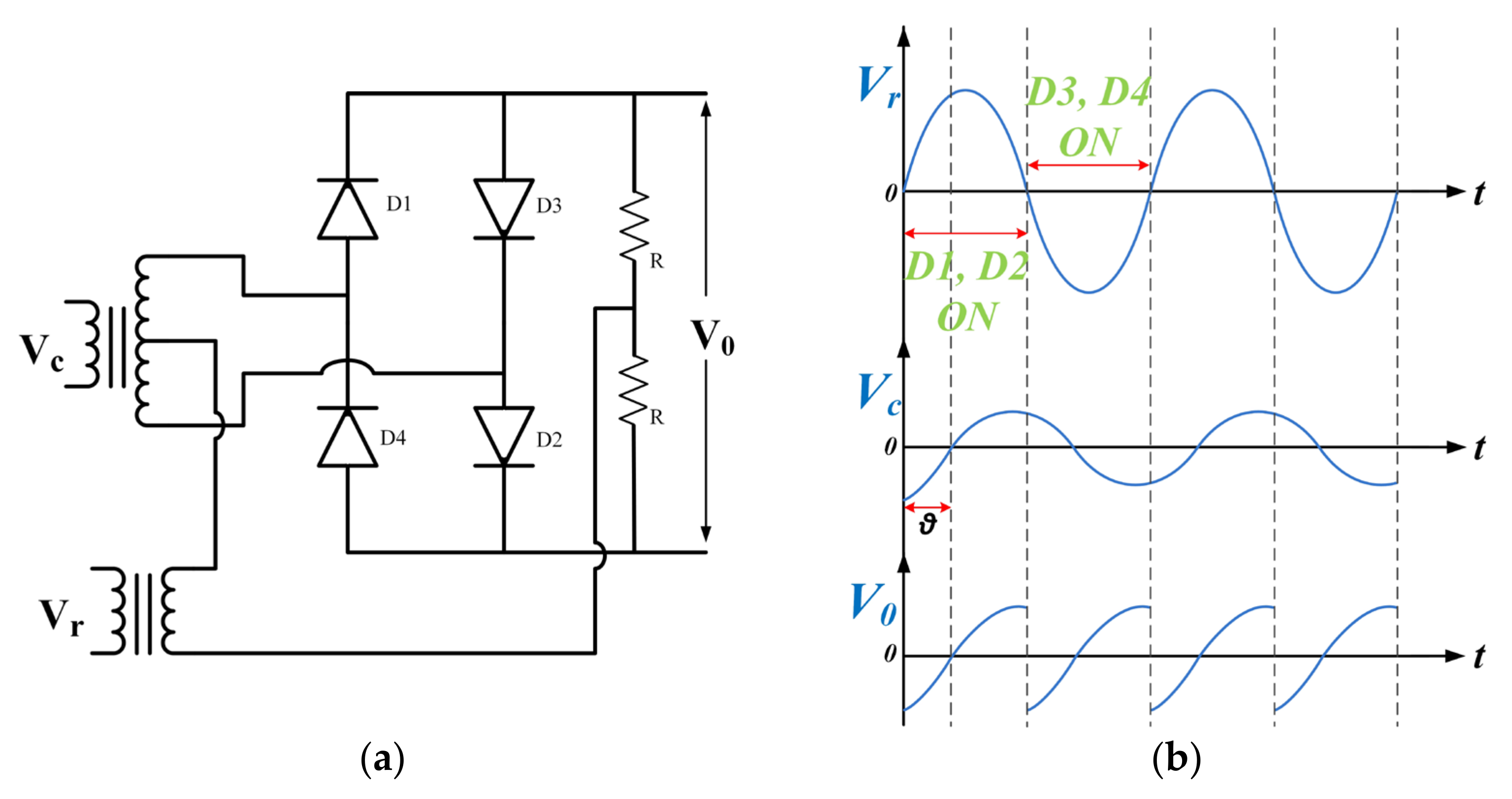
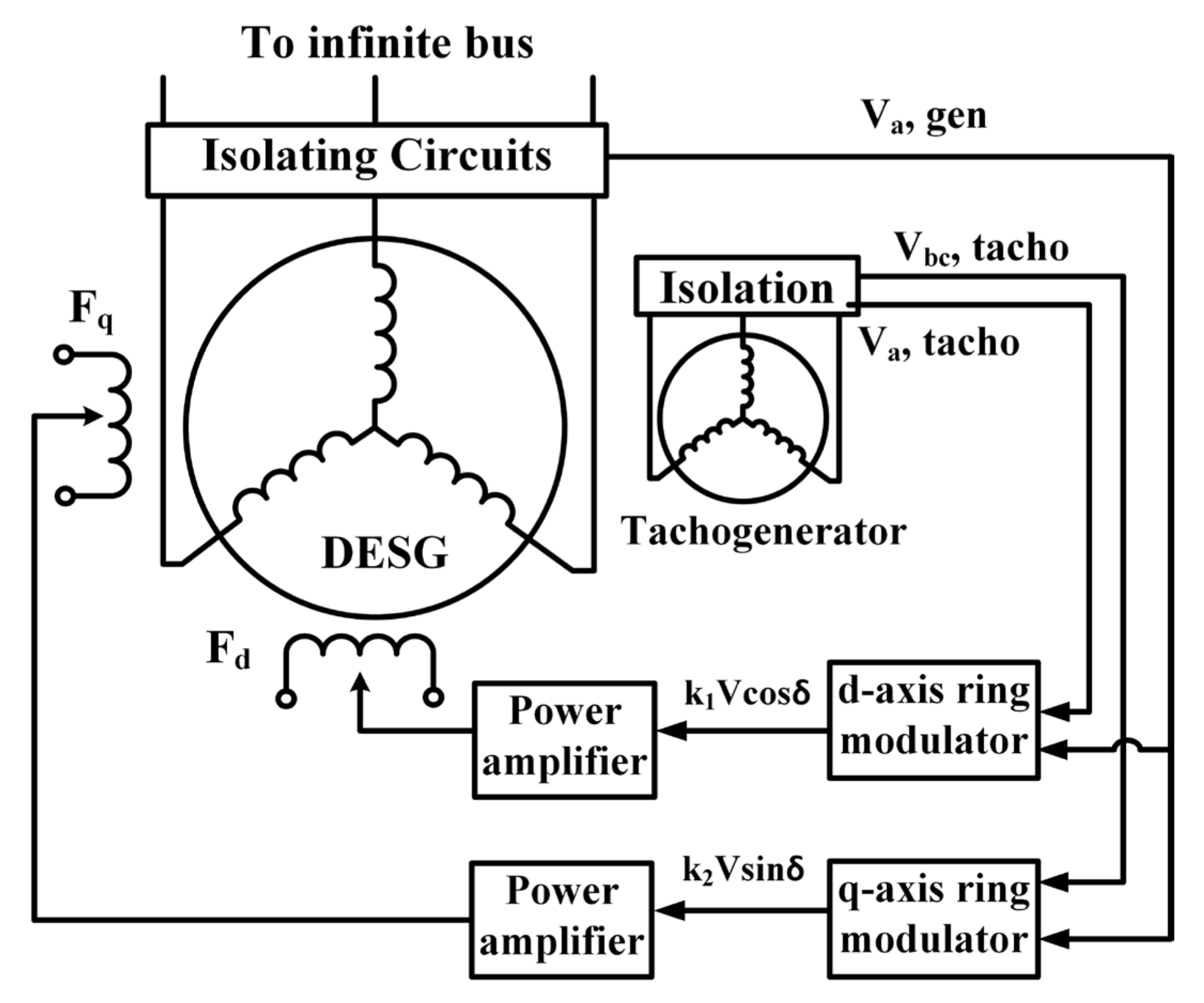
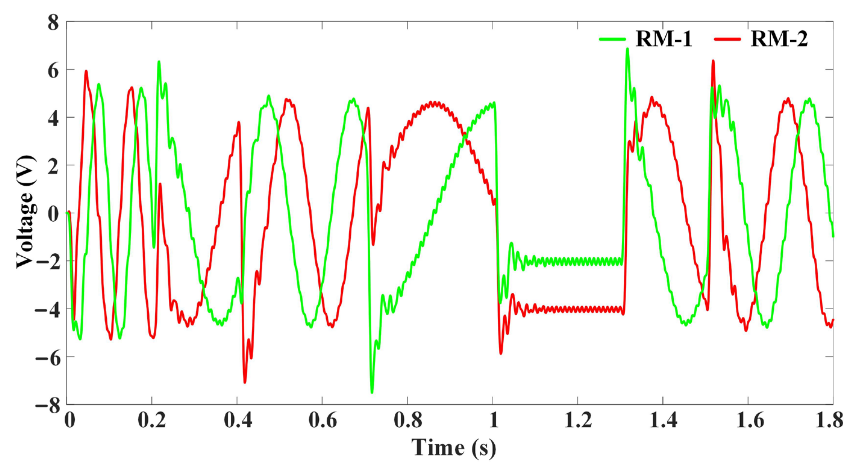
3.1. Ring Modulator and Its Operation

The control strategy presented here depends upon the two field windings of the DESG being supplied with feedback, which are essentially the d-axis and q-axis components of the terminal voltage. It is proposed to employ the d-axis and q-axis components of the machine terminal voltage for the excitation control of the DESG. These components are non-linear functions of the rotor angle and directly proportional to the terminal voltage.
The basic form of the suggested ring modulator is shown in Figure 4a. The diode bridge connection in the ring modulator resembles the full bridge converter, except that the second leg of the bridge is reversed. Moreover, there is an additional reference supply. The resistances (R) connected at the end of the circuit help to turn ON/OFF the diodes. The control voltage with phase shift (θ) is Vc, and the reference voltage is Vr. During the positive half-cycle of Vr, diodes D1 and D2 are turned ON, while diodes D3 and D4 are turned OFF. The instantaneous output voltage of the ring modulator (V0) during the positive half-cycle is the same as Vc. During the negative half-cycle of Vr, diodes D3 and D4 are ON, and the output voltage is negative of Vc. The corresponding voltage waveforms of a ring modulator are shown in Figure 4b. In Figure 4b, both inputs of the ring modulator are considered to have the same frequency, which results in a pulsating DC output. The equation of the output voltage in this condition is similar to that of a full-wave rectifier and is as follows:
V 0 = 2 2 π V c cos θ
The circuit configuration is a voltage-controlled circuit, so that the DC output is proportional to the product of the magnitude of Vc and the cosine angle between Vr and Vc. To keep the circuit in the desired operation, Vr should be much higher than Vc, and Vc should not turn ON/OFF the diodes. If the two inputs Vc and Vr do not have the same frequency, then the control voltage phasor would continuously slip with respect to the reference voltage. This results in the phase shift angle (θ) varying from 0° to 360° in a slip frequency (the difference between the control input voltage frequency and the reference input voltage frequency). Thus, the ring modulator gives the slip frequency output when there is a difference in the input supply frequencies. The equation of the output voltage when there is a difference in the two input voltages is as follows:
V 0 = 2 2 π V c cos ( s t + θ )
In the present application, the control input is directly proportional to the grid voltage, and the reference input is directly proportional to the speed voltage of the machine. In other words, the frequency of the control input is the grid frequency, and the frequency of the reference input is the frequency generated based on the rotor speed of the machine.

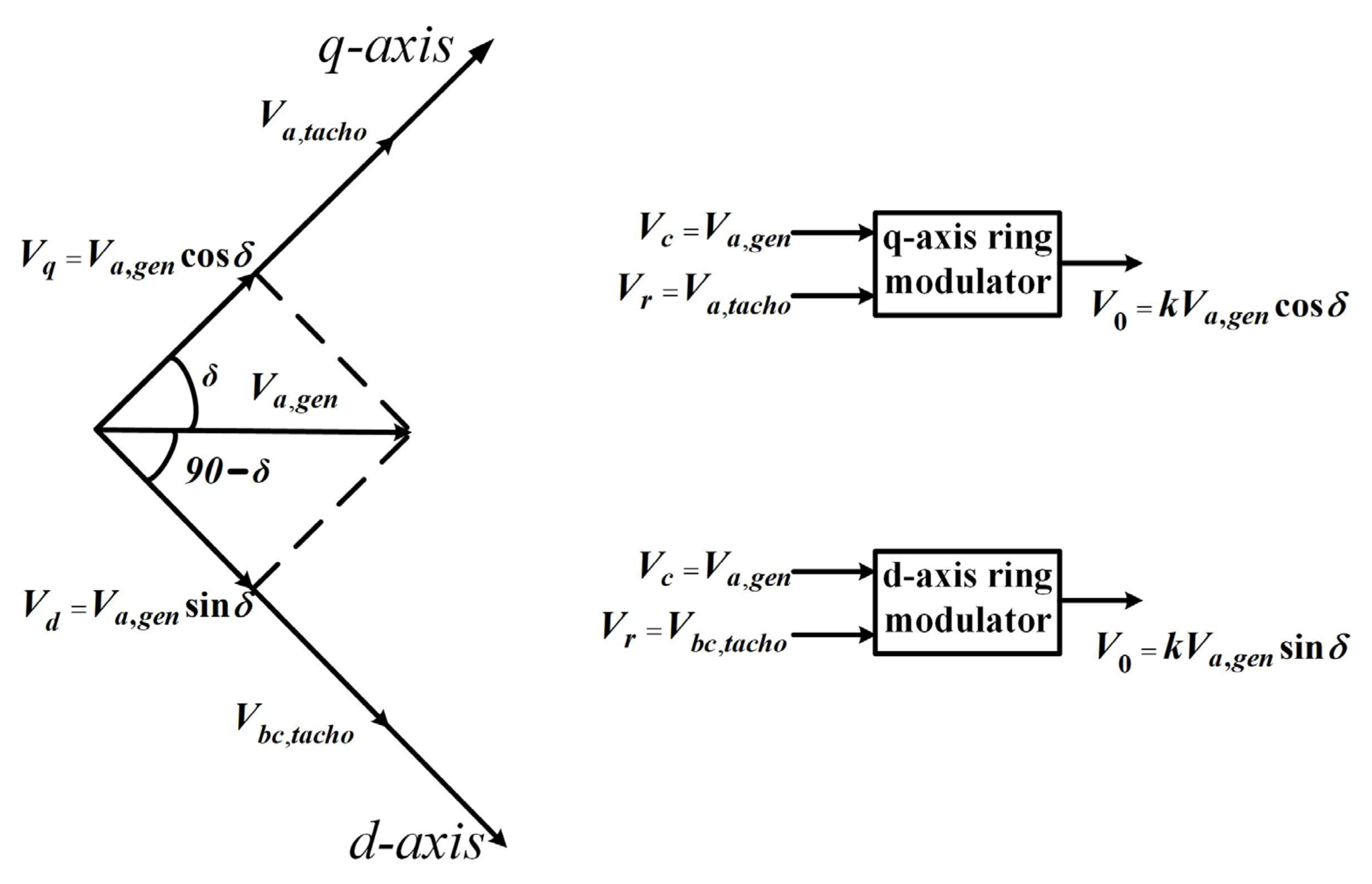
3.2. Control of DESG Using Ring Modulator

Two ring modulators, one for each axis component, are used to extract the components V c o s δ and V s i n δ of the DESG terminal voltage with slip frequency. By mounting a three-phase AC tacho-generator with the rotor and stator, aligned so that the tacho-generator voltages are in phase with the open-circuited alternator voltage, only d-axis excitation is necessary to achieve this. Figure 5 shows the excitation inputs to the d-axis and q-axis components of the terminal voltage regulators, along with the phasor diagram. The phasor diagram in Figure 5 indicates the displacement between the regulator inputs.
The DESG excited with the ring modulator circuits is shown in Figure 6. The tacho-generator is used to measure the rotor speed of the DESG. Va,tacho and Vbc,tacho are the output voltages of the tacho-generator. The output of the tacho-generator is one of the inputs to both ring modulators as a reference voltage. The control input to both ring modulators is the terminal voltage of the DESG with the grid frequency.
V c = V a , g e n ;   for   both   RM - 1   &   RM - 2 V r = V a , t a c h o ;   for   RM - 1 V b c , t a c h o ;   for   RM - 2
where RM-1 and RM-2 represent ring modulator-1 and ring modulator-2. The q-axis ring modulator is energized by the tacho-generator A-phase voltage as the reference input and the main alternator terminal voltage of the same phase, the phase shift between these inputs being the rotor angle (δ). The ring modulator develops a mean or average output proportional to V c o s δ or the q-axis component of the machine terminal voltage. In the d-axis ring modulator, the reference input is the Vbc (the line-to-line voltage) of the tacho-generator, which is in quadrature with the reference input of the q-axis ring modulator. The output developed, therefore, is proportional to V s i n δ or the d-axis component of the machine terminal voltage. The two ring modulators extract the d-axis and q-axis components of the terminal voltage of the DESG since Va,tacho, and Vbc,tacho are orthogonal to each other. The output voltage of the ring modulator is then sent through a power amplifier to amplify the level of the field current. The frequency of the outputs of these two ring modulators is always the slip frequency (the difference between the grid frequency and the natural frequency developed by the speed of the rotor).

4. System Analysis and Discussion

The analysis of the system is carried out in two conditions: operating the DESG as a wind power generator when excited by two ring modulators, and using a multi-machine power system (WSCC three-machine nine-bus test system) connected to a DESG as a wind power generator.

4.1. Analysis of DESG as Wind Generator

The block diagram of a DESG with the proposed control scheme is shown in Figure 6. The system is analyzed with constant-speed and variable-speed operation under no load and constant-impedance load conditions.

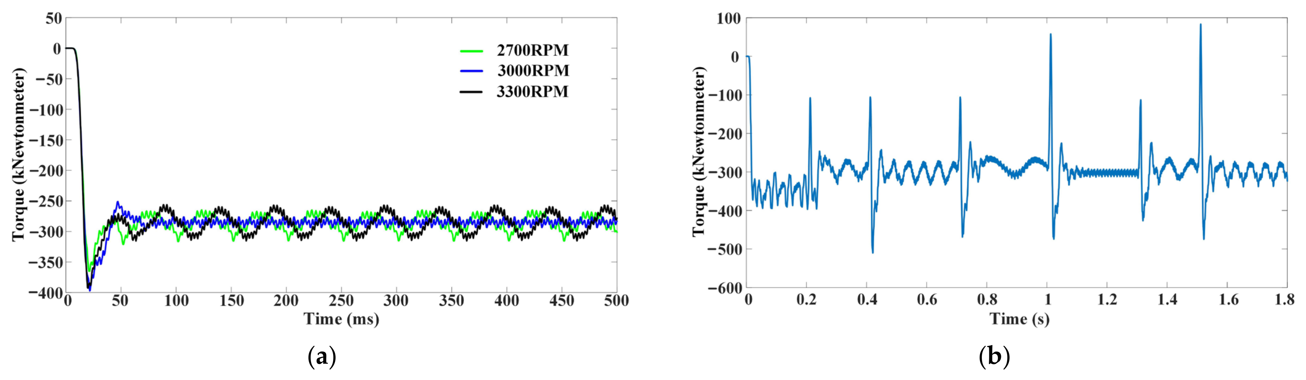
4.1.1. Constant-Speed Operation

Initially, the speed of the rotor is maintained at a constant value with a no-load condition. System simulation is performed for three different speeds: at 2700 rpm (sub-synchronous speed), at 3000 rpm (synchronous speed) and at 3300 rpm (super-synchronous speed) of the rotor. The induced phase voltage in the stator when the rotor is rotating at these speeds with no load is shown in Figure 7. Figure 8 shows the FFT analysis of the phase voltage at the above speeds. It shows that the fundamental frequency of the induced phase voltage on a stator with different rotor speeds is 50 Hz, which is also known as the synchronous frequency.

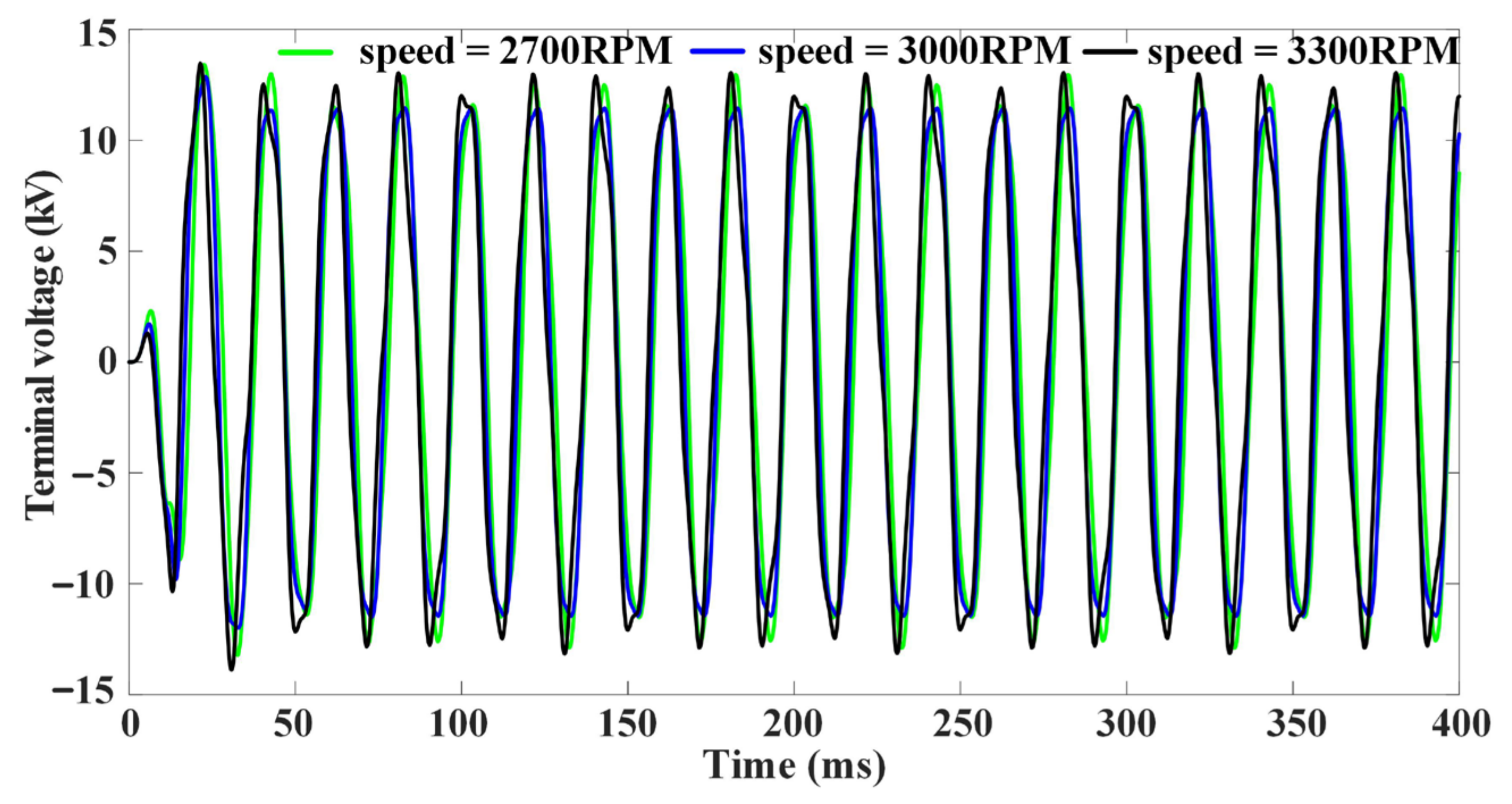
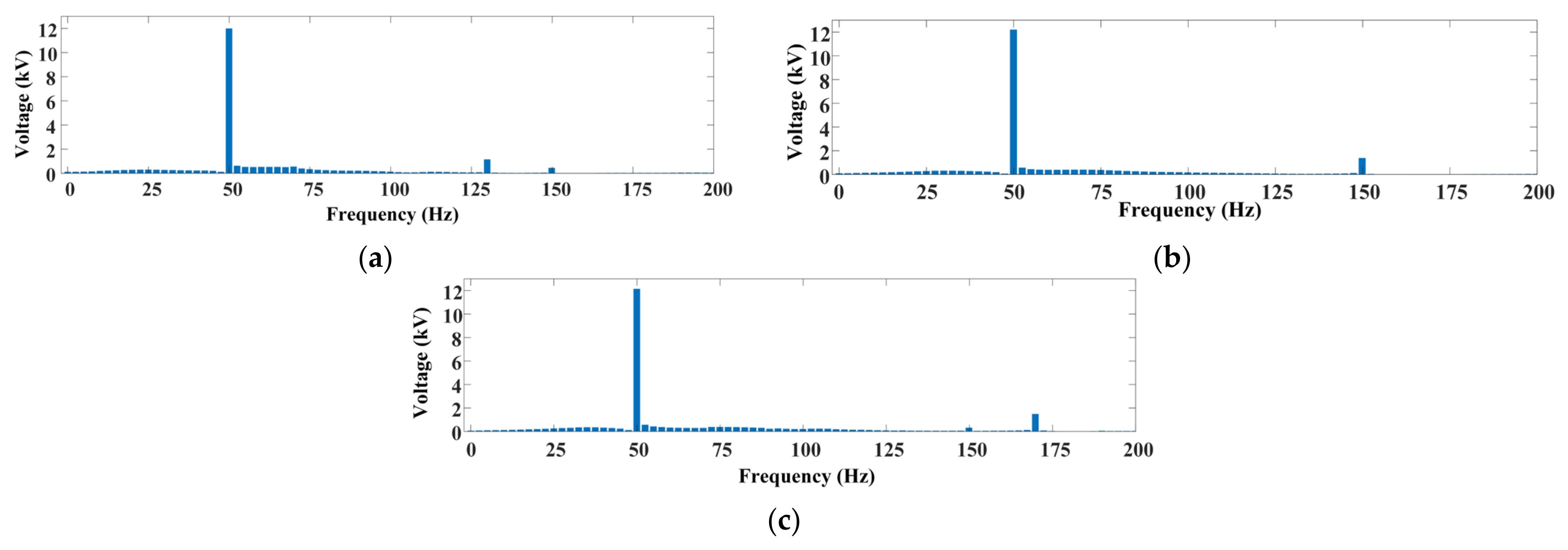
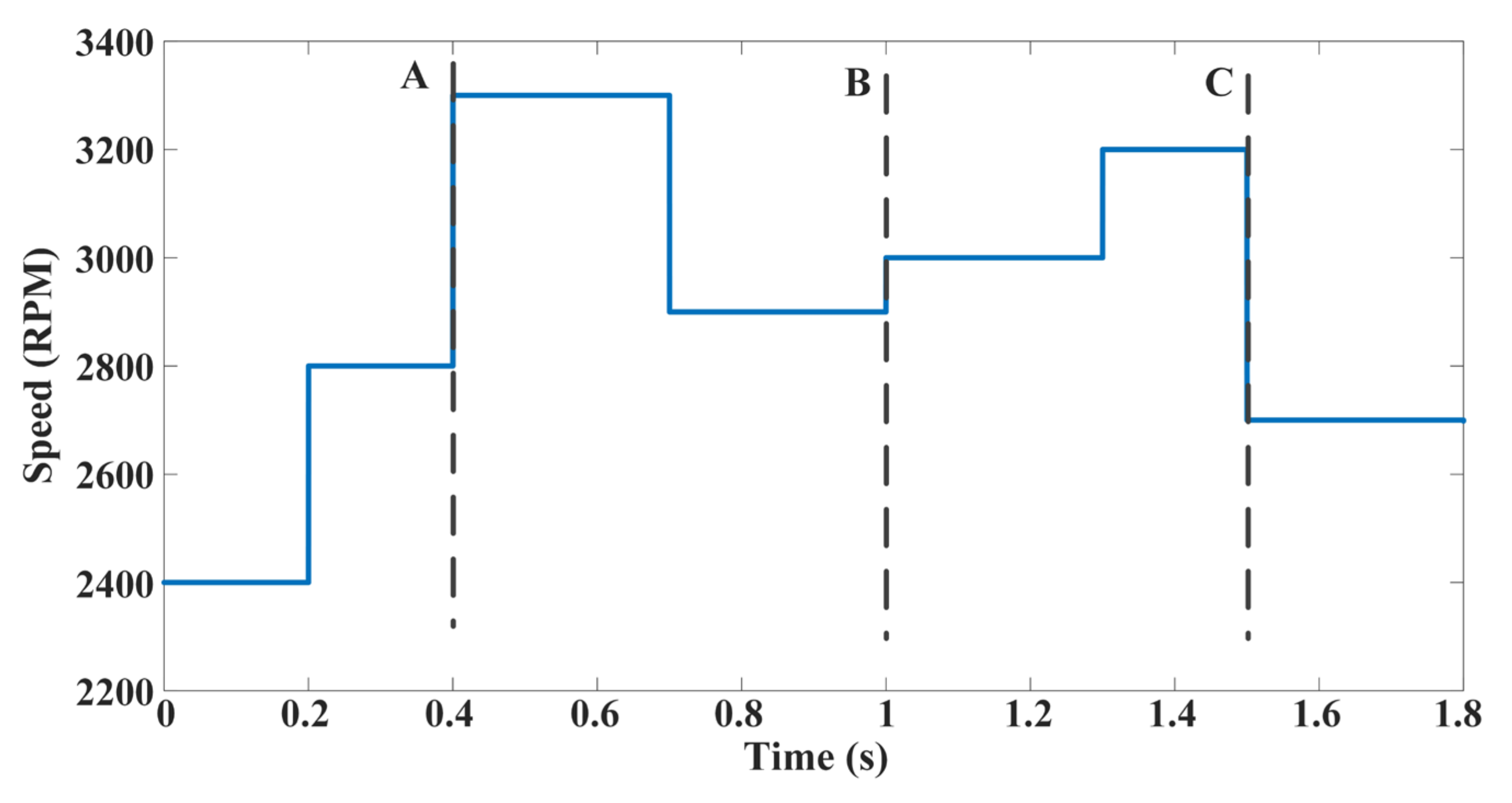
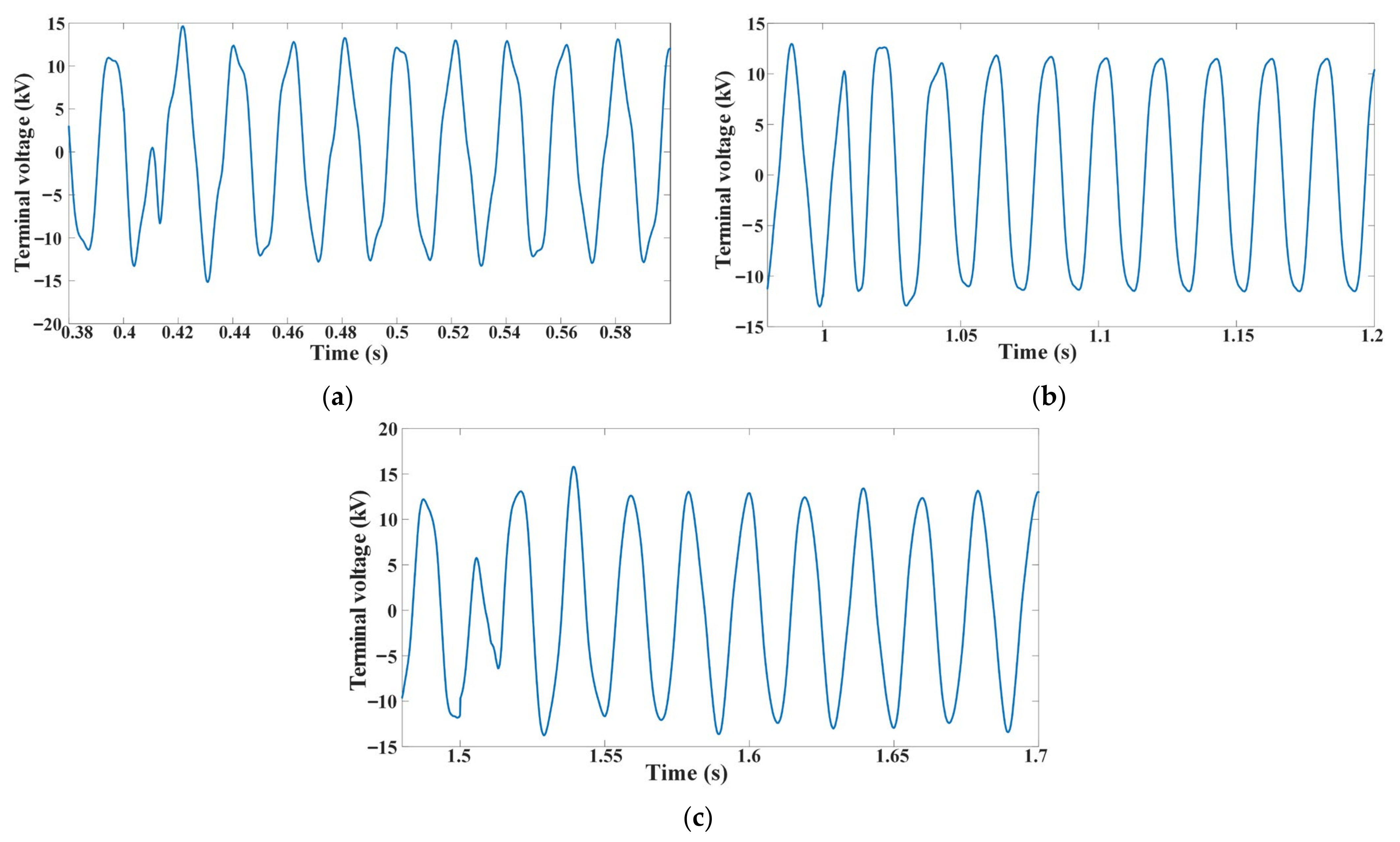
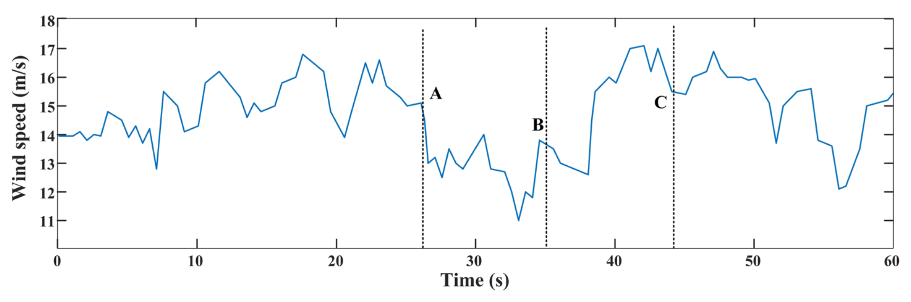
4.1.2. Variable-Speed Operation

The simulation of the system is performed using the random speed profile shown in Figure 9. Various time instances called A, B and C are highlighted in Figure 9 to include speed changes from sub-synchronous to super-synchronous speed (Instance A), sub-synchronous to synchronous speed (Instance B) and super-synchronous to sub-synchronous speed (Instance C) for the study. The effect of the variable speed on the voltage profiles of both the ring modulators and DESG is studied here. The output voltage of both ring modulators is shown in Figure 10. From Figure 10, the frequency of the ring modulator output is same as the slip frequency of the DESG, and it varies with respect to the speed of the rotor. After a step change in the rotor speed, the ring modulator takes around 50 ms to settle and generate the slip frequency. The output voltage of ring modulator-1 (RM-1) lags by 90° with the output voltage of ring modulator-2 (RM-2) before 0.4 s. At 0.4 s, the voltage output of RM-1 shifts its position to leading by 90° with the voltage output of RM-2 since the rotor speed is subjected to a change from 2800 rpm to 3300 rpm. At 1 s, the output voltage of both ring modulators becomes constant since the rotor speed is changed from 2900 rpm to 3000 rpm.
The induced voltage on the stator of the DESG with a variable rotor speed at no load is shown in Figure 11 and the magnified version of Figure 11 is shown in Figure 12. The fluctuations in voltage caused by the step change in the rotor speed can also be noticed in Figure 11 and/or Figure 12. The time instances A, B and C are related to cases a, b and c, respectively. Figure 12a describes the variation in the terminal voltage during the rotor speed change from 2800 rpm to 3300 rpm at 0.4 s. The transient nature of the terminal voltage can be observed from 0.4 s to 0.44 s. Figure 12b represents the terminal voltage variation during the speed change from 2900 rpm to 3000 rpm at 1 s. In this case, the transient behavior of the terminal voltage is observed between the time duration of 1 s to 1.04 s. It is observed from Figure 11 and Figure 12 that the highest peak in the transient variation of the terminal voltage is dependent on the quantity of change in the rotor speed. Moreover, similar variations can be seen with the induced voltage on the stator of the DESG when connected to a constant-impedance load in Figure 13.
Variations in the electromagnetic torque are shown in Figure 14. The electromagnetic torque settles at around 75 ms, when the machine changes from zero speed to synchronous speed (3000 rpm), as shown in Figure 14a. Figure 14a also shows the electromagnetic torque with rotor speeds of 2700 rpm (sub-synchronous) and 3300 rpm (super-synchronous). The torque with variable-speed operation is shown in Figure 14b. Similar to the dynamics of the ring modulator, the settling time for the torque is also around 50 ms after a sudden change in the rotor speed. The MAXWELL design of the machine includes the saliency of the DESG, which results in ripples in the torque during rotor speeds other than synchronous, as shown in Figure 14. The saliency and harmonics are ignored in the mathematical model presented in Section 2.1. Hence, the slip term is eliminated in the torque Equation (3).

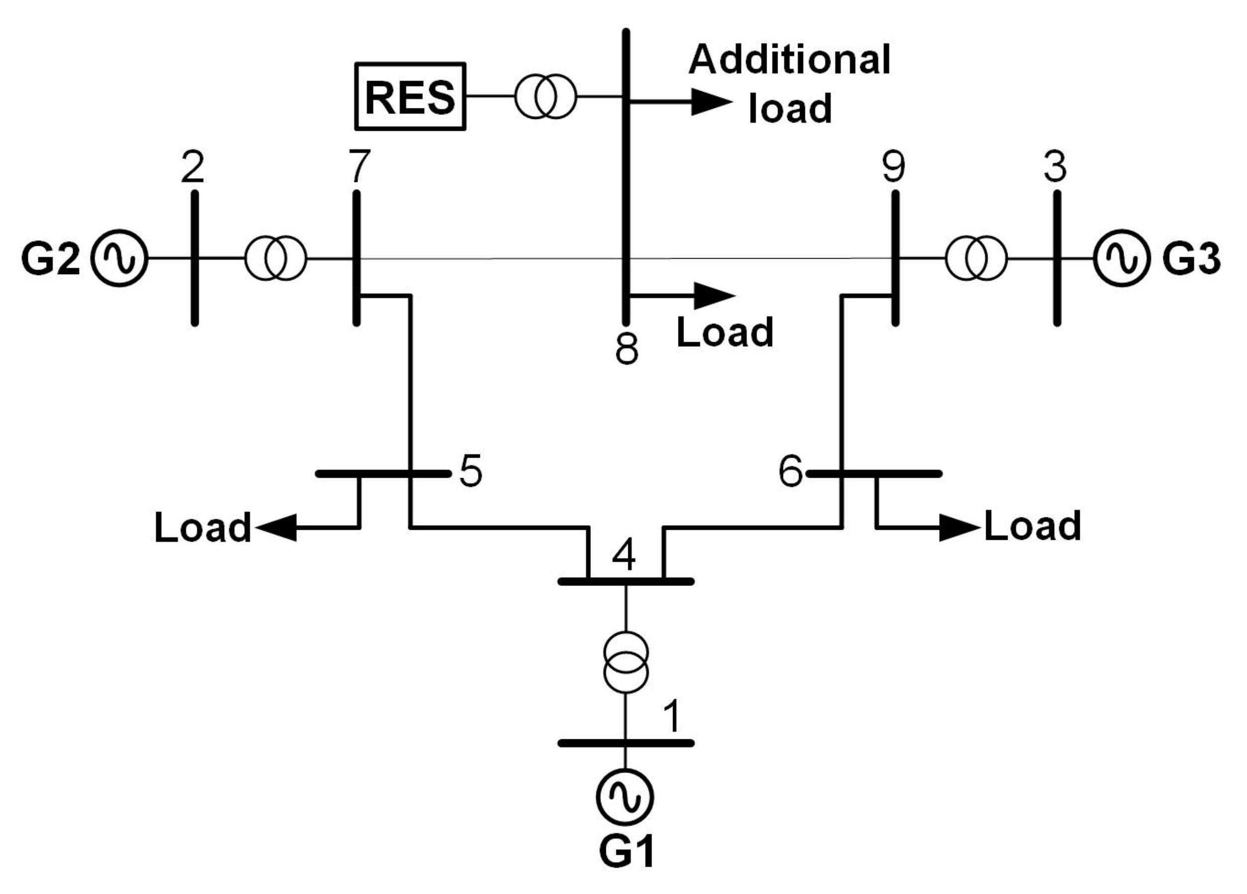
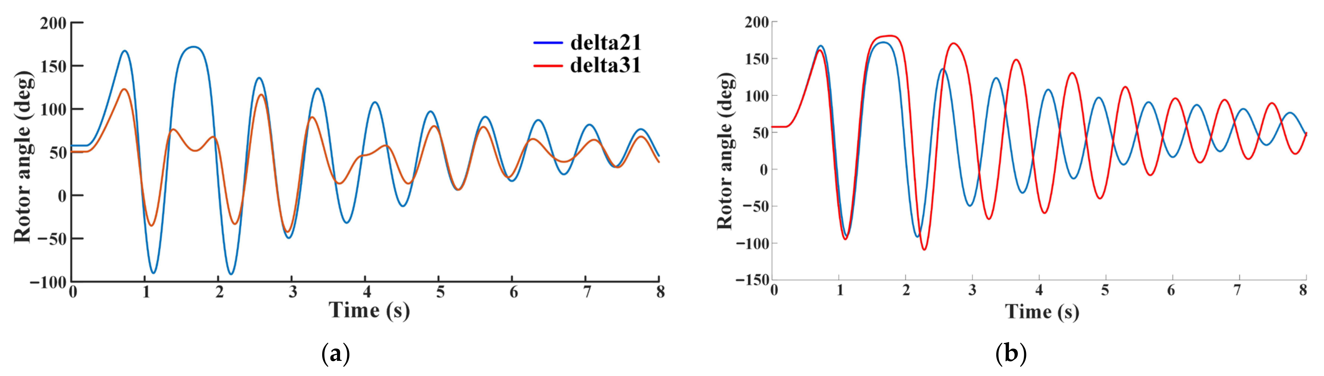
4.2. Multi-Machine System Analysis

A WSCC nine-bus, three-machine system, shown in Figure 15, connected with wind power generation at bus 8, is the multi-machine system considered for the stability analysis, and a DESG is used as a wind power generator. The mathematical models of the complete power system and DFIG are considered from [34,35]. A mathematical model of the DESG is presented in Section 2.1. A local load is connected at bus 8 to maintain the same initial conditions so that the results are comparable. To compare the results of multi-machine system stability with [35], the same type of fault and injected power are considered in this paper. The injected wind power and the base power are 80 MW and 100 MW, respectively. The rotor angles of both generators are observed, followed by a three-phase short circuit at bus 5. The study is carried out for both constant-speed and variable-speed operations.

4.2.1. Constant-Speed Operation

Initially, a three-phase short circuit fault is created at bus 5 at 0.2 s and the rotor angles of both generators are observed with a fault clearing time of 464 ms. The same is shown in Figure 16a and 464 ms is the CCT for this condition. Moreover, the rotor angle variation of generator 2 (G2) with the same fault is observed when the wind generator is the DFIG and the CCT in this case is 463 ms. This result is compared with that of the DESG as a wind generator and the same is shown in Figure 16b. From Figure 16b, the oscillations in the rotor angle are damped out faster with the DESG when compared to the DFIG.

4.2.2. Variable-Speed Operation

In Figure 17 [34,35], the wind speed profile is displayed together with various time instances (referred to as A–C) to illustrate the impact of various alterations in the speed profile. A three-phase fault is created at all three instances (A, B and C) of time to study the transient stability through the critical clearing time (CCT). Initially, the wind speed is considered to be 13.8 m/s, and, at time instance C (44.2 s), the fault instance, the speed of the wind is 15.5 m/s. Table 3 compares the CCT of generator 2 (G2) when the system is connected to the DFIG as well as the DESG with variable power injection into the system. The CCT of G2 at fault time instance A (26.25 s) is 454 ms with the DFIG as a wind generator and 503 ms with the DESG as wind generator, with an improvement of 49 ms in the CCT. It is observed from Table 3 that there is an improvement in the CCT at all three fault instances when the DESG is used as a wind power generator.

5. Conclusions

A dual-field excited synchronous generator is designed in MAXWELL-2D. The DESG presented here has the physical structure of a four-pole rotor. However, the DESG is designed to work as a two-pole machine by altering the winding construction of the rotor with two different supplies. Moreover, a simple and novel non-linear control strategy employing a ring modulator is proposed to generate slip frequency voltages. The control signals employed are essentially the d-axis and q-axis components of the alternator terminal voltage. This novel control strategy ensures the interfacing of a windmill with the grid. The basic idea is to excite the field windings with the slip frequency current rather than a pure DC as in conventional machines. The stators of both the DFIG and DESG are connected to the grid through a transformer and the rotor of the DFIG back-to-back converter. Whereas the stator of the DESG is directly connected to the grid through a transformer, the field is excited by the proposed ring modulator. Thus, the use of a back-to-back converter is eliminated. The proposed control strategy is validated by simulating the DESG excited with ring modulators as the controllers of the field windings. The simulation is performed for both constant- and variable-rotor-speed operations at no load and with a constant-impedance load. Results show that the ring modulator gives the slip frequency output based on the speed of the rotor of the DESG, which is required to generate the synchronous frequency (50 Hz) and makes the DESG act as a wind power generator. The ring modulator takes approximately 50 ms to adjust with the change in the rotor speed. Moreover, the stability analysis of the multi-machine system (three-machine nine-bus WSCC) when connected to the DESG with the proposed control as a wind generator is performed and 464 ms is the observed CCT. Variations in the rotor angle of the machines show that both the DESG and DFIG give almost the same CCT. However, the DESG shows better damping performance. Meanwhile, in the variable-speed operation, the improvement in CCT with the DESG used as a wind generator is 49 ms when a fault is created at 26.25 s (Instance A).

Author Contributions

Conceptualization, A.A. and S.S.B.; methodology and validation, A.A. and S.S.B.; writing—original draft preparation, A.A.; writing—review and editing, S.S.B., D.Z. and P.S.; supervision, S.S.B., D.Z. and P.S. All authors have read and agreed to the published version of the manuscript.

Funding

This research received no external funding.

Data Availability Statement

Data are contained within the article.

Conflicts of Interest

The authors declare no conflicts of interest.

Nomenclature

DESGDual-Field Excited Synchronous Generator
PMSGPermanent Magnet Synchronous Generator
DFIGDoubly Fed Induction Generator
RM-1 and RM-2Ring Modulator-1 and Ring Modulator-2
CCTCritical Clearing Time
G2 and G3Generator-2 and Generator-3
Va,tacho, Vbc,tachoA-Phase Voltage and Line-Line Voltage of Tacho-Generator
Vr, VcReference and Control Input Voltages to the Ring Modulator
Va,genA-Phase Voltage of DESG
θPhase Shift in Vr with Respect to Vc
δRotor Angle
λ ¯ s and λ ¯ f Flux Linkage Vectors of Stator and Rotor, Respectively
V ¯ s , I ¯ s , V ¯ s and I ¯ f Voltage and Current Vectors of Stator and Rotor, Respectively
Z ¯ t and XmStator Impedance and Mutual Reactance
sMachine Slip

References

  1. Saidur, R.; Islam, M.R.; Rahim, N.A.; Solangi, K.H. A Review on global wind energy policy. Renew. Sustain. Energy Rev. 2010, 14, 1744–1763. [Google Scholar] [CrossRef]
  2. Gualtieri, G. A comprehensive review on wind resource extrapolation models applied in wind energy. Renew. Sustain. Energy Rev. 2019, 102, 215–233. [Google Scholar] [CrossRef]
  3. Zeng, Z.; Yang, H.; Zhao, R.; Cheng, C. Topologies and control strategies of multi-functional grid-connected inverters for power quality enhancement: A comprehensive review. Renew. Sustain. Energy Rev. 2013, 24, 223–270. [Google Scholar] [CrossRef]
  4. Duan, Y.; Harley, R.G. Present and future trends in wind turbine generator designs. In Proceedings of the 2009 IEEE Power Electronics and Machines in Wind Applications, Lincoln, NE, USA, 24–26 June 2009; pp. 1–6. [Google Scholar] [CrossRef]
  5. Yin, M.; Xu, Y.; Shen, C.; Liu, J.; Dong, Z.Y.; Zou, Y. Turbine Stability-Constrained Available Wind Power of Variable Speed Wind Turbines for Active Power Control. IEEE Trans. Power Syst. 2016, 32, 2487–2488. [Google Scholar] [CrossRef]
  6. Ngamroo, I. Review of DFIG wind turbine impact on power system dynamic performances. IEEJ Trans. Electr. Electron. Eng. 2017, 12, 301–311. [Google Scholar] [CrossRef]
  7. Kaloi, G.S.; Wang, J.; Baloch, M.H. Active and reactive power control of the doubly fed induction generator based on wind energy conversion system. Energy Rep. 2016, 2, 194–200. [Google Scholar] [CrossRef]
  8. Yunus, A.M.S.; Abu-Siada, A.; Masoum, M.A.S.; El-Naggar, M.F.; Jin, J.X. Enhancement of DFIG LVRT Capability During Extreme Short-Wind Gust Events Using SMES Technology. IEEE Access 2020, 8, 47264–47271. [Google Scholar] [CrossRef]
  9. Polinder, H.; van der Pijl, F.; de Vilder, G.-J.; Tavner, P. Comparison of direct-drive and geared generator concepts for wind turbines. IEEE Trans. Energy Convers. 2006, 21, 725–733. [Google Scholar] [CrossRef]
  10. Arani, M.F.M.; Mohamed, Y.A.-R.I. Assessment and Enhancement of a Full-Scale PMSG-Based Wind Power Generator Performance Under Faults. IEEE Trans. Energy Convers. 2016, 31, 728–739. [Google Scholar] [CrossRef]
  11. Zhang, F.; Yu, S.; Wang, Y.; Jin, S.; Jovanovic, M.G. Design and Performance Comparisons of Brushless Doubly Fed Generators With Different Rotor Structures. IEEE Trans. Ind. Electron. 2019, 66, 631–640. [Google Scholar] [CrossRef]
  12. Strous, T.D.; Polinder, H.; Ferreira, J.A. Brushless doubly-fed induction machines for wind turbines: Developments and research challenges. IET Electr. Power Appl. 2017, 11, 991–1000. [Google Scholar] [CrossRef]
  13. Cheng, M.; Hua, W.; Zhang, J.; Zhao, W. Overview of Stator-Permanent Magnet Brushless Machines. IEEE Trans. Ind. Electron. 2011, 58, 5087–5101. [Google Scholar] [CrossRef]
  14. Wang, Q.; Niu, S. Design, Modeling, and Control of a Novel Hybrid-Excited Flux-Bidirectional-Modulated Generator-Based Wind Power Generation System. IEEE Trans. Power Electron. 2018, 33, 3086–3096. [Google Scholar] [CrossRef]
  15. Kjaer, A.B.; Korsgaard, S.; Nielsen, S.S.; Demsa, L.; Rasmussen, P.O. Design, fabrication, test, and benchmark of a magnetically geared permanent magnet generator for wind power generation. IEEE Trans. Energy Convers. 2020, 35, 24–32. [Google Scholar] [CrossRef]
  16. Smith, O.J.M. Synchronous-flux generator. Electr. Eng. 1958, 77, 605–610. [Google Scholar] [CrossRef]
  17. Morsy, M.S.; Amer, H.H.; Badr, M.A.; El-Serafi, A.M. Transient Stability of Synchronous Generators with Two-Axis Slip Frequency Excitation. IEEE Power Eng. Rev. 1983, PER-3, 27–28. [Google Scholar] [CrossRef]
  18. Krause, P.C.; Towle, J.N. Synchronous machine damping by excitation control with direct and quadrature axis field windings. IEEE Trans. Power Appar. Syst. 1969, PAS-88, 1266–1274. [Google Scholar] [CrossRef]
  19. Harley, R.G.; Adkins, B. Stability of synchronous machine with divided-winding rotor. Proc. IEE 1970, 117, 933–947. [Google Scholar] [CrossRef]
  20. Subramaniam, P.; Malik, O. Dynamic-stability analysis of d.w.r. synchronous generator with feedback-stabilised voltage and angle regulators. Proc. Inst. Elect. Eng. 1971, 118, 1768–1774. [Google Scholar] [CrossRef]
  21. Reddy, A.A.; Bhat, S.S.; Ugale, R.T. Design and FEM analysis of dual excited synchronous generator. In Proceedings of the 2017 National Power Electronics Conference (NPEC), Pune, India, 18–20 December 2017; pp. 302–306. [Google Scholar]
  22. Xu, G.; Wang, Z.; Liu, B.; Zhan, Y.; Li, W.; Zhao, H.; Huang, H.; Yu, H. Finite-element calculation of electromagnetic characteristics and steady-state stability of dual-excited synchronous generator. IET Electr. Power Appl. 2021, 15, 1300–1313. [Google Scholar] [CrossRef]
  23. Xu, G.; Hu, Y.; Hao, X.; Zhan, Y.; Zhao, H.; Liu, X.; Luo, Y. The Relationship of Magnetomotive Force Under Different Excitation Modes of Dual-Excited Synchronous Generator. IEEE Trans. Magn. 2017, 54, 8200704. [Google Scholar] [CrossRef]
  24. Nakamura, M. Electric Vehicle Control Device. Japan Patent JPWO2011135777A1, 18 June 2013. [Google Scholar]
  25. Hunt, S.R. Calibrated Slip Synchronous Machine. U.S. Patent US10587176B2, 10 March 2020. [Google Scholar]
  26. D’Arco, S.; Piegari, L.; Tricoli, P. A novel control of Dual-Excited Synchronous machines for variable-speed wind turbines. In Proceedings of the 2011 IEEE Trondheim PowerTech, Trondheim, Norway, 19–23 June 2011; pp. 1–6. [Google Scholar] [CrossRef]
  27. Piegari, L.; Rizzo, R.; Tricoli, P. High Efficiency Wind Generators with Variable Speed Dual-Excited Synchronous Machines. In Proceedings of the 2007 International Conference on Clean Electrical Power, Capri, Italy, 21–23 May 2007; pp. 795–800. [Google Scholar]
  28. Yonah, Z.O.; El-Serafi, A.M.; Krause, A.E. Regulation of terminal voltage and output frequency of a variable-speed dual-excited synchronous generator by using a computer-based two-phase excitation system. In Proceedings of the Canadian Conference on Electrical and Computer Engineering, Vancouver, BC, Canada, 14–17 September 1993; Volume 2, pp. 1165–1168. [Google Scholar]
  29. Yonah, Z.O.; El-Serafi, A.M.; Krause, A.E. Computer-controlled VSCF generating system using a dual-excited synchronous generator. In Proceedings of the IEEE Pacific Rim Conference on Communications, Computers, and Signal Processing, Victoria, BC, Canada, 17–19 May 1995; pp. 619–622. [Google Scholar]
  30. Smith, I.R.; Creighton, G.K.; Kaynak, M.O. Theoretical and Experimental Study of an Asynchronized Synchronous Machine. IEEE Trans. Ind. Electron. Control Instrum. 1975, IECI-22, 501–506. [Google Scholar] [CrossRef]
  31. Reddy, A.A.; Bhat, S.S. Modeling of Dual Excited Synchronous Generator with slip frequency excitation. In Proceedings of the 2020 IEEE First International Conference on Smart Technologies for Power, Energy and Control (STPEC), Nagpur, India, 25–26 September 2020; pp. 1–3. [Google Scholar] [CrossRef]
  32. Yassin, H.M.; Abdel-Wahab, R.R.; Hanafy, H.H. Active and Reactive Power Control for Dual Excited Synchronous Generator in Wind Applications. IEEE Access 2022, 10, 29172–29182. [Google Scholar] [CrossRef]
  33. Abdel-Wahab, R.R.; Yassin, H.M.; Hanafy, H.H. Dual Excited Synchronous Generator a Suitable Alternative for Wind Applications. In Proceedings of the 2020 IEEE 14th International Conference on Compatibility, Power Electronics and Power Engineering (CPE-POWERENG), Setubal, Portugal, 8–10 July 2020; pp. 352–357. [Google Scholar] [CrossRef]
  34. Mitra, A.; Chatterjee, D. Active Power Control of DFIG-Based Wind Farm for Improvement of Transient Stability of Power Systems. IEEE Trans. Power Syst. 2015, 31, 82–93. [Google Scholar] [CrossRef]
  35. Agarala, A.; Bhat, S.S.; Mitra, A.; Zychma, D.; Sowa, P. Transient Stability Analysis of a Multi-Machine Power System Integrated with Renewables. Energies 2022, 15, 4824. [Google Scholar] [CrossRef]
  36. Anderson, P.M.; Fouad, A.A. Power System Control and Stability, 2nd ed.; John Wiley & Sons: Hoboken, NJ, USA, 2008. [Google Scholar]
Figure 1. Schematic view of DESG.
Energies 17 00456 g001
Figure 2. Magnetic flux density distribution in DESG.
Energies 17 00456 g002
Figure 3. Air gap field flux (Bag in Tesla).
Energies 17 00456 g003
Figure 4. Ring modulator; (a) circuit diagram and (b) voltage waveforms.
Energies 17 00456 g004
Figure 5. Extraction of d-axis and q-axis components of terminal voltage.
Energies 17 00456 g005
Figure 6. Schematic block of controller for DESG.
Energies 17 00456 g006
Figure 7. Induced voltage on stator at no load for different rotor speeds.
Energies 17 00456 g007
Figure 8. FFT of stator voltage for rotor speeds (a) 2700 rpm, (b) 3000 rpm and (c) 3300 rpm.
Energies 17 00456 g008
Figure 9. Rotor speed profile of DESG.
Energies 17 00456 g009
Figure 10. Output voltage of both ring modulators with variable speed.
Energies 17 00456 g010
Figure 11. Induced voltage on stator with variable rotor speed at no load, highlighting three specific scenarios (ac) of speed change.
Energies 17 00456 g011
Figure 12. Magnified version of Figure 11 at different instances of time. (a) Speed shift from sub-synchronous to super-synchronous at 0.4 s. (b) Speed shift from sub-synchronous to synchronous at 1 s. (c) Speed shift from super-synchronous to sub-synchronous at 1.5 s.
Energies 17 00456 g012
Figure 13. Induced voltage on stator with variable rotor speed with constant-impedance load.
Energies 17 00456 g013
Figure 14. Electromagnetic torque (a) with different rotor speeds and (b) with variable rotor speed.
Energies 17 00456 g014
Figure 15. Three-machine nine-bus WSCC system.
Energies 17 00456 g015
Figure 16. Rotor angle variations of (a) G2 and G3 with DESG fault at 464 ms, (b) G2 with both DESG and DFIG with fault created at 463 ms at bus 5.
Energies 17 00456 g016
Figure 17. Wind speed profile.
Energies 17 00456 g017
Table 1. Design parameters of stator of DESG.
SpecificationValue
Outer diameter (mm)2350
Inner diameter (mm)1140
Slots36
Coil pitch (slots)14
Core length3450
Slots/pole/phase6
Air gap (mm)70
Poles2
WindingDouble layer (Lap)
Table 2. Design parameters of rotor of DESG.
SpecificationValue
Outer diameter (mm)1000
Inner diameter (mm)365
Indexed slots
Actual slots28
Core length3500
Slots/pole/phase7
Poles2
WindingDouble layer (Lap)
Table 3. CCT of G2 when connected to different wind generators with variable-speed operation.
Fault InstanceAt A (26.25 s)At B (35 s)At C (44.2 s)
DFIG454 ms468 ms456 ms
DESG503 ms498 ms486 ms
Disclaimer/Publisher’s Note: The statements, opinions and data contained in all publications are solely those of the individual author(s) and contributor(s) and not of MDPI and/or the editor(s). MDPI and/or the editor(s) disclaim responsibility for any injury to people or property resulting from any ideas, methods, instructions or products referred to in the content.

