Article

Enhancing Loadability of Transmission Lines Using Static Synchronous Series Compensator Devices: A Case Study of the Syrian Network

1
Department of Electrical Power Engineering, Faculty of Mechanical and Electrical Engineering, Tishreen University, Latakia P.O. Box 2237, Syria
2
Department of Electrical and Computer System Engineering, Faculty of Engineering, Monash University, Clayton, VIC 3800, Australia
*
Author to whom correspondence should be addressed.
Energies 2024, 17(2), 390; https://doi.org/10.3390/en17020390
Submission received: 29 October 2023 / Revised: 25 December 2023 / Accepted: 10 January 2024 / Published: 12 January 2024
(This article belongs to the Section F1: Electrical Power System)

Abstract

:
In response to global energy demand, the enhancement of transport capacity in electrical transmission lines is deemed essential. The conventional method of constructing new lines is considered costly, time-consuming, and subject to constraints imposed by economic and environmental factors. Among various emerging solutions aimed at enhancing the passive capacity of transmission lines, the technology of flexible AC transmission systems (FACTS) has been demonstrated to be highly effective. This paper proposes the utilization of the static synchronous series compensator (SSSC), a closed-loop control system and a type of FACTS, to alleviate the overloading of transmission lines in the Syrian electrical network. To achieve this objective, the network is first modeled to identify the overloaded transmission lines. Subsequently, the particle swarm optimization (PSO) algorithm is employed for the optimal sizing and allocation of SSSCs within the network. The findings showcase the significant reduction in loads on critically overloaded transmission lines subsequent to the successful implementation of SSSC devices. This serves to validate the improvements made to the existing infrastructure of the Syrian electrical network’s transmission lines, without necessitating the construction of new transmission lines.

1. Introduction

It is anticipated that a twofold increase in the demand for energy utilization in the global power sector will occur between the years 2015 and 2050 [1]. The continual growth in demand for electric power necessitates the significant expansion of existing electrical networks [2]. Critical issues, such as the overload of transmission lines, which are highly undesirable and detrimental to power reliability, can result from insufficient interconnection and management of electrical networks [3]. Resorting to the construction of new transmission lines to address these problems is economically unviable. Therefore, when electrical networks are managed with an incomplete control mechanism, the maximum load limit of transmission lines approaches their thermal load limits [4]. To address this issue effectively, it is imperative to implement a robust power flow control mechanism for transmission lines.
Electric power transmission lines exhibit predominantly inductive characteristics, resulting in significant impedance and voltage drop along long transmission lines. The power flow through these lines depends not only on the impedance of each transmission line but also on the amplitude of the transmitter and receiver end voltages, as well as the voltage angle [5]. These factors collectively influence the efficiency and performance of power transmission systems. Hence, the disparity between the voltage and angle at the transmitter and receiver ends allows for the manipulation of power flow in transmission lines through adjustments in line impedance or voltage angle, as supported by previous studies [6].
Traditional methods to enhance the power transmission capacity of lines have relied on the use of capacitors connected via mechanical breakers [4]. However, these methods suffer from slow control response, which is also contingent upon the line current. Fortunately, advancements in the power electronics industry have paved the way for new flexible AC transmission system (FACTS) controllers that offer diverse applications in power transmission systems. These controllers, such as the static compensator (STATCOM), static VAR compensator (SVC), unified power flow controller (UPFC), and static synchronous series compensator (SSSC), can be installed in serial, parallel, or hybrid configurations [7]. The FACTS devices, which are recognized by IEEE as an integral part of AC transmission systems, employ power electronics and other control mechanisms to significantly augment the control and capacity of power transmission lines [8].
The utilization of the SSSC is observed as a means of implementing serial compensation for power flow control and reactive power compensation in transmission lines. The SSSC is characterized by a synchronous voltage source driven by electronic switches, coupled with a transformer that is serially linked with a transmission line [9,10,11]. Within the framework of the SSSC, an almost sinusoidal voltage with varying in magnitude in quadrature with the current within the line is injected into a transmission line in a series configuration, effectively emulating either an inductive or capacitive reactance integration in series with the transmission line [9,12].
Several studies focus on the performance evaluation of the serial compensator, as presented in [9,13,14,15,16]. In [9], the SSSC is modeled, and it is demonstrated that power flow in the transmission line always decreases for the injected voltage via the SSSC when emulating an inductive reactance, and vice versa when emulating a capacitive reactance. In [17], a control design approach for the SSSC is proposed utilizing the linearized model. For eigenvalue analysis and validations, the SSSC performance is tested based on an SMIB power system case. In [18], three possible techniques are presented for Voltage regulation of the SSSC.
To enhance transient stability and damping in a multi-machine power system, a nonlinear adaptive control scheme for the SSSC is discussed in [19]. The SSSC device is treated as a first-order voltage resource, and the multi-machine system is simplified into a two-machine model. By employing the exact feedback linearization theory and adaptive control law, the nonlinear adaptive controller for the SSSC accounts for unknown system parameters to improve robustness, as validated through simulation results. In another study, an intelligent control system for SSSC is proposed in [20], which utilizes an online self-tuning Proportional–Integral–Derivative (PID) controller to suppress sub-synchronous resonance (SSR). Treating the PID controller similar to a single-layer neural network, its parameters can be updated in real-time. In the evaluation of this control system, an IEEE 14-bus system is employed and simulated using the PSAT software [21]. In [22], SSSC and UPFC are utilized to enhance the available transfer capability (ATC). Furthermore, [23] focuses on deploying SSSC to enhance the loadability of the Nigerian network, which operates at 330 kV with 41 buses.
This paper proposes the deployment of SSSC as a solution to alleviate the overloading on the Syrian network, specifically focusing on overloaded transmission lines at 230 kV and 400 kV. By optimally placing SSSCs in the tramission lines, the transmitted power is effectively reduced while ensuring feed reliability. Consequently, this approach not only enhances the overall reliability of the Syrian network but also can significantly mitigate the occurrence of faults resulting from line overloading. The contributions of this paper are outlined as follows:
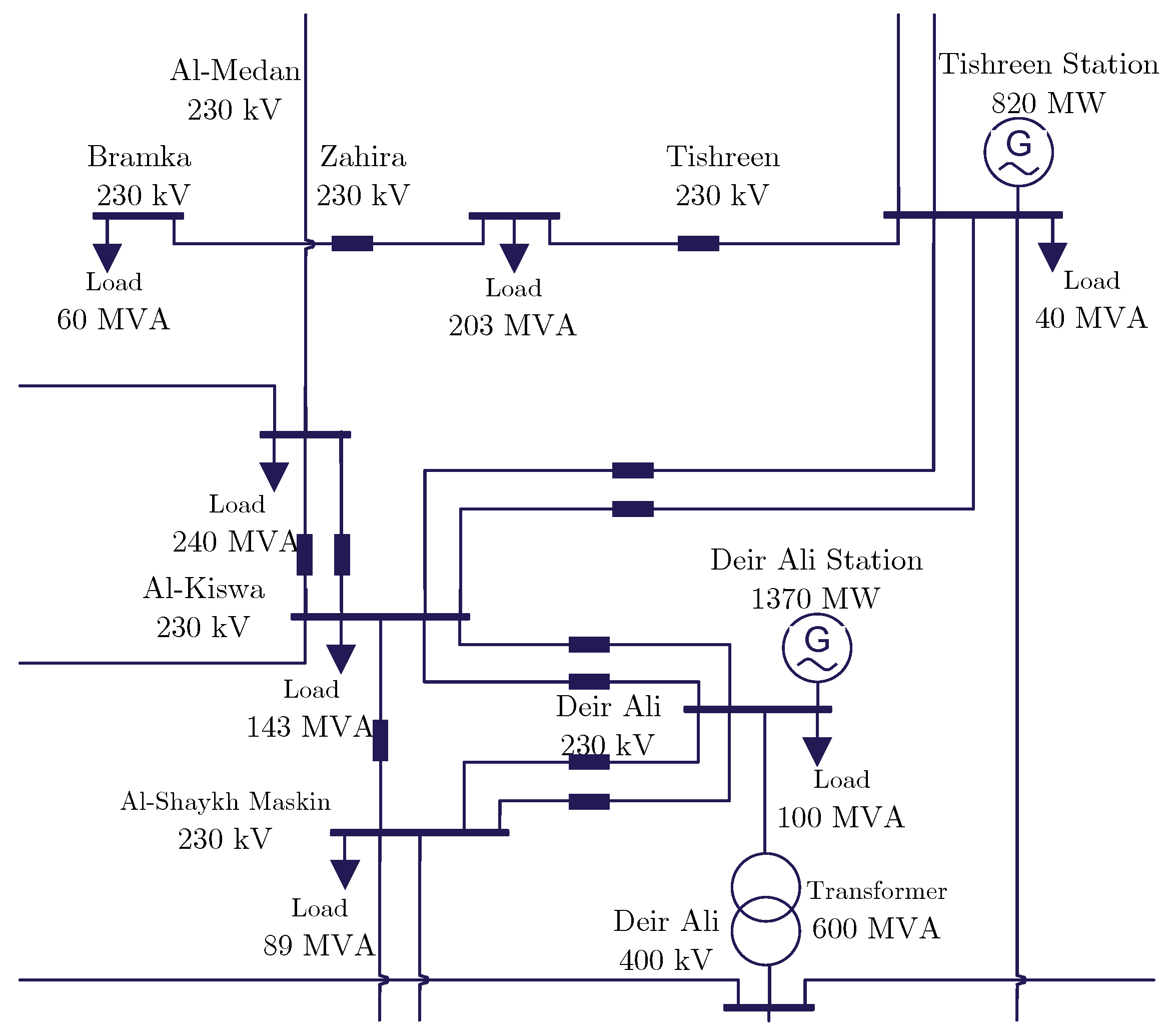
  • Detailed and accurate modeling of the Syrian transmission network based on real data. This involves incorporating crucial parameters such as transmission line lengths, conductor types, generation capacities, and peak loads.
  • Proposing the deployment of SSSC units for contingency management by preventing the overloading of transmission lines, thereby enhancing the overall stability and reliability of the Syrian transmission network.
  • Achieving the optimal placement of SSSCs is through the utilization of the particle swarm optimization (PSO) algorithm. This ensures efficient and effective sizing and allocation, leading to the lowest possible active power loss value. The performance of the PSO algorithm is also compared with two algorithms, namely genetic algorithm (GA) and firefly algorithm (FFA).
The paper is organized as follows: Section 2 provides an overview of the considered electrical network, including generation stations, transmission lines, and the issue of overloading. Section 3 explains the proposed solution to enhance loadability of the Syrian electrical network including the concepts and control topology of the SSSC. It also discusses the use of PSO for optimal allocation of SSSC in the transmission lines. Section 4 presents simulation results demonstrating the effective enhancement of loading in the transmission lines of the Syrian grid using SSSC. Finally, Section 5 concludes the paper.

2. Overview of the Syrian Electrical Network

The accurate modeling of a network is of utmost importance in power flow analysis. This involves incorporating power stations, transmission lines, transformers, and loads into the model. By doing so, the power flow study can effectively identify significant failures, such as overloading exceeding the thermal load limit, occurring on the transmission lines. Consequently, it becomes essential to determine the load ratio for these lines during flow analysis.
This paper investigates the Syrian electrical network under normal operating conditions, with a focus on evaluating the load percentage. The network comprises multiple power stations with their corresponding generation capacities, as outlined in Table 1, reflecting data from 2011. Using 2011 data is justified due to post-2011 data collection challenges. However, it is crucial to mention that this older data captures worst-case scenarios, including network overloads, contingencies, and generation/load peaks, which are key aspects to be investigated in this paper. Figure 1 illustrates the geographical distribution of these power stations across the country. At the transmission line level, both 230 kV and 400 kV lines are present throughout the network, spanning different lengths. The loads are aggregated and connected downstream of the 230/66 kV transformers.
The Syrian electrical network exhibits several instances of transmission line overloading. To provide further illustration, the paper includes a power flow analysis of the network utilizing the Newton–Raphson algorithm. The operational scenario being investigated represents a snapshot of the system at a specific operating point. This particular time instance (snapshot) represents an overloading operational scenario. The power flow analysis is conducted using the PSAT software, identifies some transmission lines that are operating above their nominal capacity. For instance, Figure 2, which depicts the electric diagram of a section of the network, shows the overloaded transmission lines connecting the Dear-Ali power station to the aggregated load at Al Kiswa. It is worth mentioning that the transmission line connecting Deir Ali-Al Kiswa is a type ACSR tension 230 kV Section 400/50. This transmission line is designed to withstand a current within an acceptable thermal permittivity limit of 567.8 A. However, when overloaded, it is subjected to a proportional load of 125%, resulting in a peak current of 709.75 A. Consequently, the overload on this line amounts to 141.95 A. Another example of an overloaded transmission line is the Zahira-Tishreen connection, also a type ACSR tension 230 kV line. Its nominal current capacity is 567.8 A. However, it is overloaded with a proportional load of 115%, leading to a peak current of 652.97 A. The overload on this line has increased by 85.17 A. Further analysis on the loading of the Syrian electrical network are provided in the Results section.
These instances of transmission line overloading highlight the critical condition of the Syrian electrical network. Addressing and resolving these issues are crucial for maintaining the network’s reliability and ensuring the delivery of electricity without compromising its integrity. To address these overloading issues, the application of a compensator such as the SSSC can be explored, aiming to increase the capacity of these lines without the need for building new transmission lines.

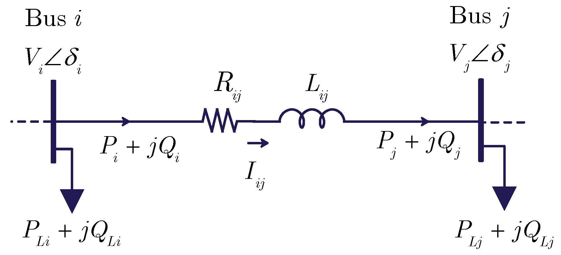
3. Proposed Solution to Enhance Loadability of the Syrian Electrical Network

The aim of this paper is to enhance the loadability of the Syrian electrical network. To do so, a solution relies on SSSC units within is selected. The rationale behind the selection of the SSSC solution in our paper is based on its well-established effectiveness in improving electricity grid performance. In details, the proposed solution combines the deployment of SSSCs within the network and the achievement of optimal allocation of these SSSCs using the PSO algorithm. Subsequent sections will delve into further details regarding the utilization of SSSCs and the PSO algorithm in this context.

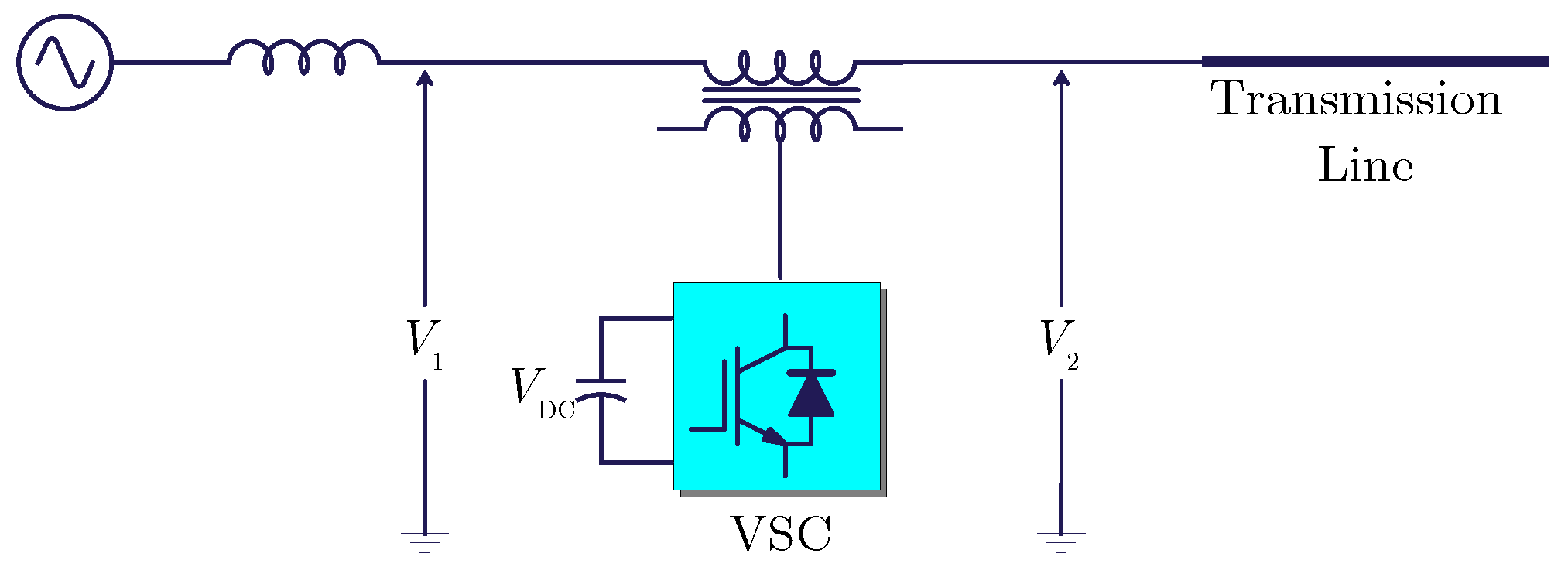
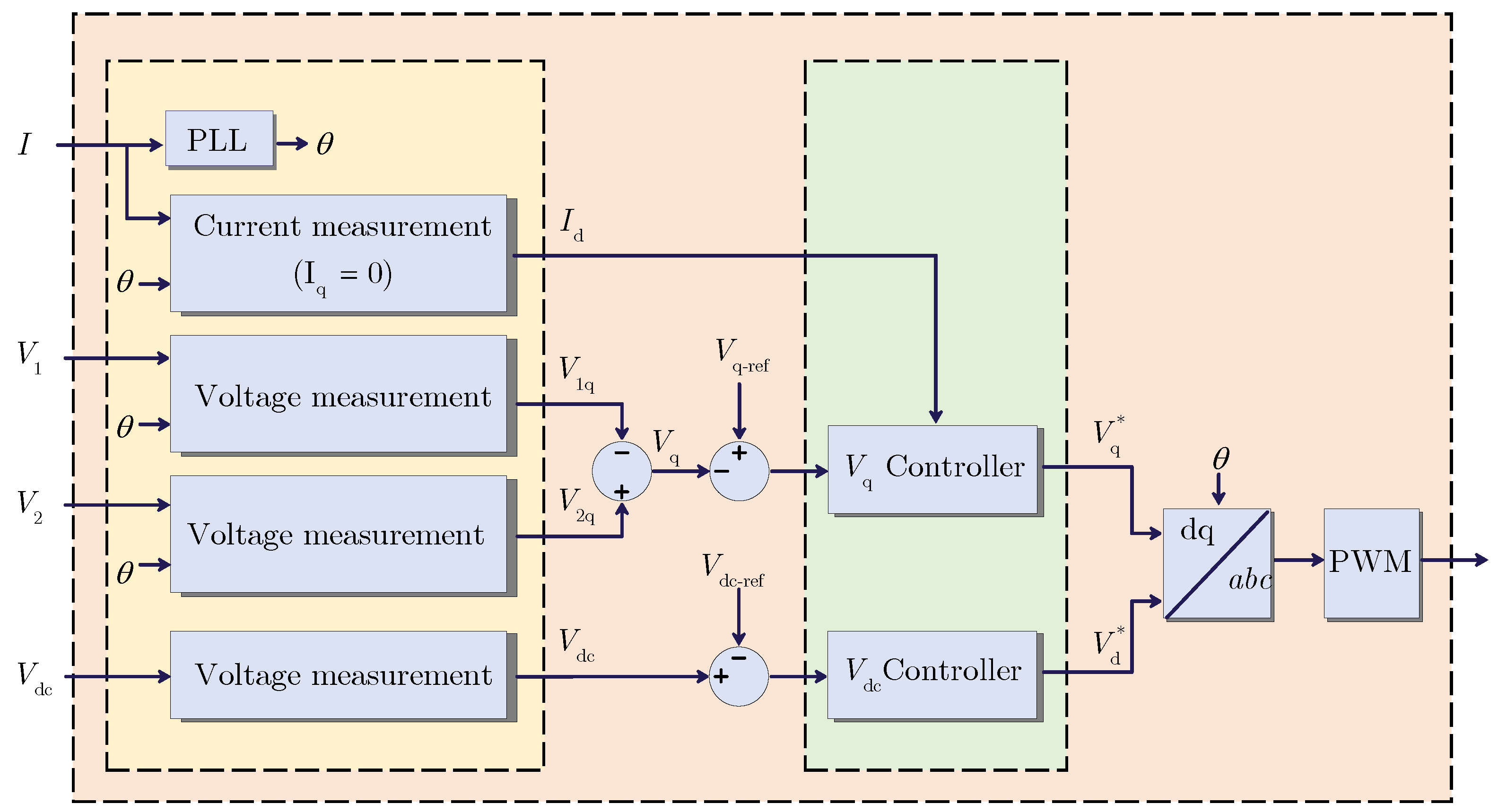
3.1. Statistic Synchronous Series Compensator

The SSSC belongs to the FACTS family and is designed as a serial device. While it shares similarities with the compensator STATCOM, the key difference lies in their connection to the transmission line. The SSSC is connected in series with the transmission line, whereas the STATCOM is connected in parallel to the transmission line. Typically, the SSSC is connected to the AC system through a transformer [24].
Figure 3 demonstrates the integration of the SSSC into a transmission line. The amplitude of the voltage injected by the SSSC is adjusted using a DC-AC voltage source converter (VSC) connected in series with the transmission line. The VSC utilizes power electronics transistors, such as GTO, IGBT, or IGCT, to synthesize the switched output voltage ( V conv ). In this study, an IGBT-based VSC is utilized. The VSC is supported by a DC capacitor that acts as a DC side ( V DC ) and is charged from the AC side. It draws a small amount of power from the line to cover the circuit losses. The energy stored in the DC capacitor is then utilized to generate the controllable voltage injected into the transmission line. This configuration ensures that the injected voltage remains perpendicular to the line current, i.e., a 90-degree phase difference with the line current. Through closed-loop control, the SSSC injects the desired sinusoidal voltage into the transmission line, thereby regulating power flow and enhancing load-carrying capacity. The SSSC adds the injected voltage ( V q ) in series with the line voltage, enabling variable impedance compensation, either capacitive or inductive.
Figure 4 presents the implementation of the closed-loop control structure for the SSSC. A phase-locked loop (PLL) utilizing the positive component of the line current is used to obtain the synchronization phase angle, θ = ω t , with the grid. This angle is then used to calculate the direct and quadrature components of the three-phase current and voltage waveforms ( I d , I q , V 1 d , V 1 q , V 2 d , V 2 q ). AC and DC voltage regulators are employed to determine the reference voltage components of the inverter ( V d * , V q * ), which correspond to the desired DC voltage reference, V dc ref , and the injected voltage, V q ref .
The actual and shift active and reactive power transported through the transmission line, when the transmitting voltage and the receiving voltage are equal, can be described mathematically as shown in Equations (1) and (2), respectively [25,26].
Prior to the connection of the SSSC, the power flow expressions between the two interconnected areas through a line with reactance ( X L ), as depicted in Figure 3, can be expressed as follows:
P = V 2 X L sin δ Q = V 2 X L [ 1 cos δ ]
where | V | = | V 1 | = | V 2 | and δ = δ 1 δ 2 .
After the SSSC connection, which emulates a compensating reactance ( j X q ) in series with the line’s inductive reactance ( j X L ), the power flow expressions considering the SSSC become:
P = V 2 X e f f sin δ = V 2 X L 1 X q X L sin δ Q = V 2 X L [ 1 cos δ ] = V 2 X L [ 1 X q X L ] ( 1 cos δ )
where X e f f denoted the effective reactance of the transmission line. It encompasses two components: the actual inductance of the tranmision line, denoted as X L , and the additional inductance inserted by the SSSC, denoted as X q . When the SSSC operates in the inductive mode, the value of X q is negative, while in the capacitive mode, it is positive [27].
Referring to Equation (2), which describes the load flow of active and reactive power through the transmission line after connecting the SSSC, it is evident that these power values can be controlled by manipulating the angle δ and the voltage V by modifying the injected voltage V q . These adjustments are expected to influence the overall impedance of the transmission line. The SSSC injects a voltage orthogonal to the line current, simulating the addition of either an inductive or capacitive impedance in series with the transmission line. As a result, the power flow across the line increases with a capacitive impedance simulation and decreases with an inductive impedance simulation.

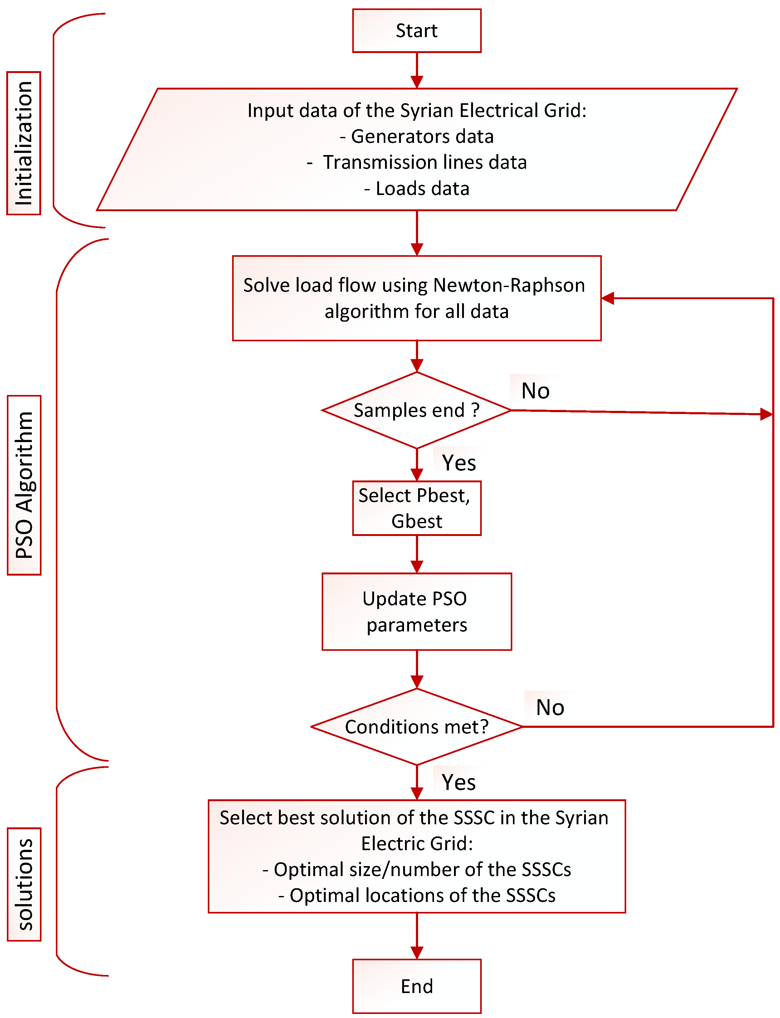
3.2. Optimal SSSC Sizing and Allocation Using PSO Algorithm

The optimal sizing and placement of SSSCs within the Syrian 230 kV electrical network transmission lines is determined using the PSO algorithm in the proposed study. The objective is to minimize active power losses in transmission lines by selecting suitable sizes and locations for SSSCs.
To further illustrate the formulation of the objective function, the two-bus transmission line depicted in Figure 5 is considered. The system consists of two buses (Bus i and Bus j), with the transmission line connecting them represented by its resistive-inductive model ( R i j , L i j ).
In this system, the following equations can be written:
P i = P j + P L o s s i j Q i = Q j + Q L o s s i j
where P i , Q i are the active and reactive power at Bus i; P j , Q j are the active and reactive power at Bus j; and P L o s s i j , Q L o s s i j are the active and reactive power losses in the transmission line from Bus i to Bus j.
The terms of active and reactive power losses can be calculated as follows [28]:
P L o s s i j = R i j R i j 2 + X i j 2 ( V i 2 2 V i V j cos δ i j + V j 2 )
Q L o s s i j = X i j R i j 2 + X i j 2 ( V i 2 2 V i V j cos δ i j + V j 2 )
Subsequently, the objective function for the SSSCs sizing and allocation problem is formulated. The aim is to minimize power loss, enhance the voltage profile, minimize capital investment, and maximize savings. The mathematical formulation of the objective function is described below
minimize F = C L o s s P r L o s s T o t a l + C p Q r C T o t a l minimize F = C L o s s i = 1 N b u s 1 P L o s s i + C p j = 1 N S S S C Q r C j
where F represents the total costs (USD/year), C L o s s represents the annual cost per unit of power loss (USD/kW/year), C p denotes the total SSSCs purchase and installation cost ($/kVar), P r L o s s T o t a l and Q r C T o t a l stand for the total power loss in line i j , Q r C j denotes the total reactive power injected at location j, N b u s indicates the total number of buses, and N S S S C reflects the optimal number of SSSCs placements. Therefore, the annual total cost of SSSCs can be calculated as:
Total SSSCs cos t = C p × Q r C j T o t a l Life Expectancy $ / year
It is worth noting that the objective function is solved while considering the electricity grid network constraints. First, the power flow in any given transmission line should not exceed the maximum limit. Second, the voltage at any given bus must fall within the permissible minimum and maximum limits. Third, the optimal number of SSSCs must not exceed the maximum number of possible SSSC locations.
Figure 6 proposed depicts the flowchart outlining the optimal sizing and allocation of the SSSCs utilizing the PSO algorithm. The first step involves initialization, incorporating input parameters for the Syrian Grid data (e.g., generation, transmission lines, buses, and load). Subsequently, the PSO algorithm is employed in the second step to ascertain the optimal size and locations of SSSCs, considering various parameter combinations (different sizes in MVA and numbers of SSSCs). During each iteration of the PSO algorithm, the computation of load flow is achieved using the Newton–Raphson algorithm. Finally, the best solution, indicating the optimal size and locations of the SSSCs, is selected based on the criterion of minimizing active power losses in the network. In summary, these steps collectively ensure an efficient allocation of SSSCs within the Syrian electric grid to prevent overloading.
Further details on the parameters of the PSO algorithm and the optimal size and locations of the SSSCs are presented in the Results section. For a deeper understanding of the Newton-Raphson method for power flow analysis and the PSO algorithm, interested readers can refer to [29,30], respectively.

4. Results

This section presents simulation results to show the efficacy of utilizing SSSC to enhance the loadability of the transmission lines in the Syrian electricity grid. The results presented here are organized into three distinct cases. Case 1 focuses on integrating the SSSC into a two-bus transmission system to showcase the load conditions before and after activating the SSSC. Case 2 examines the power flow of the Syrian electricity grid prior to incorporating the SSSC, thereby highlighting the prevailing instances of overloading in specific transmission lines. Case 3 highlights the obtained results from the transmission lines subsequent to the integration of the SSSCs. In this case, 10 SSSCs are optimally allocated within the network employing the PSO algorithm.

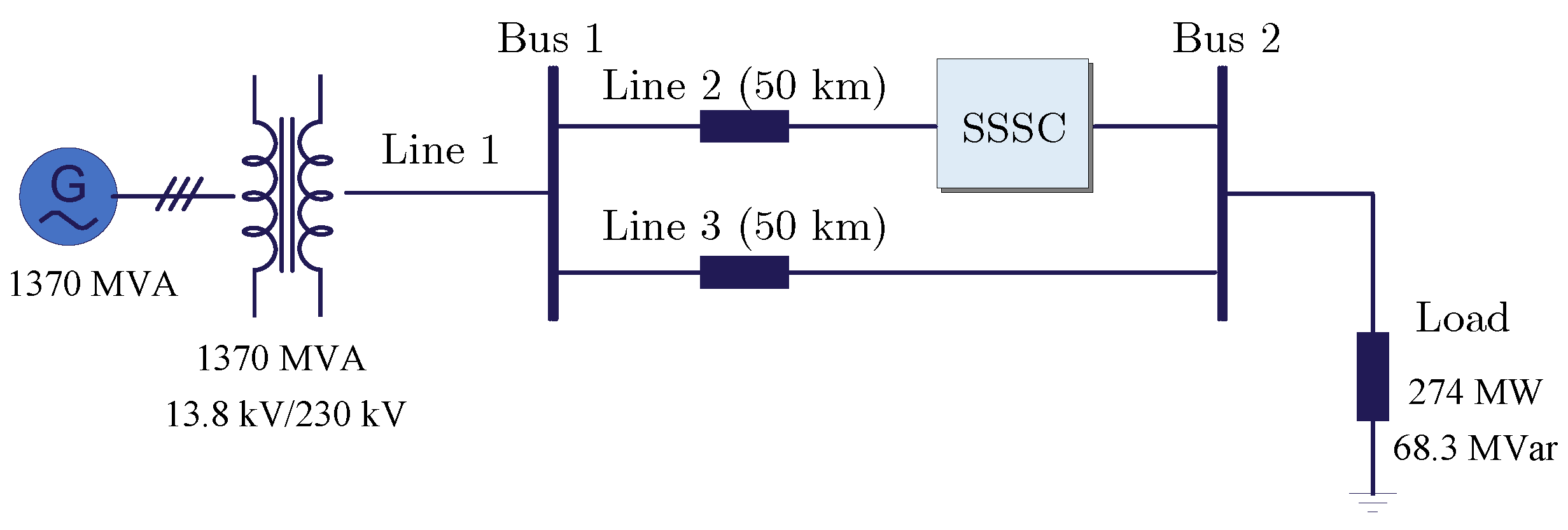
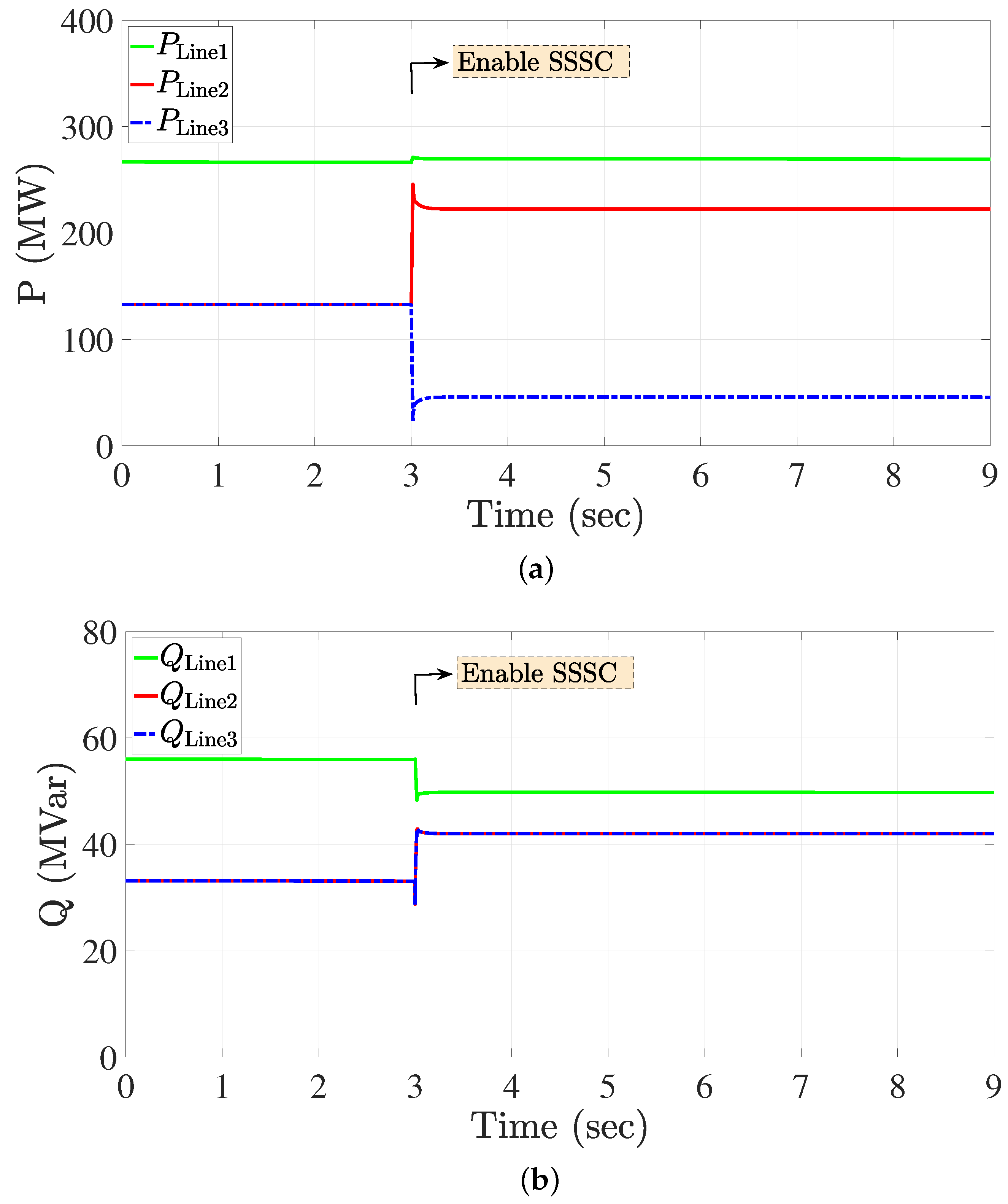
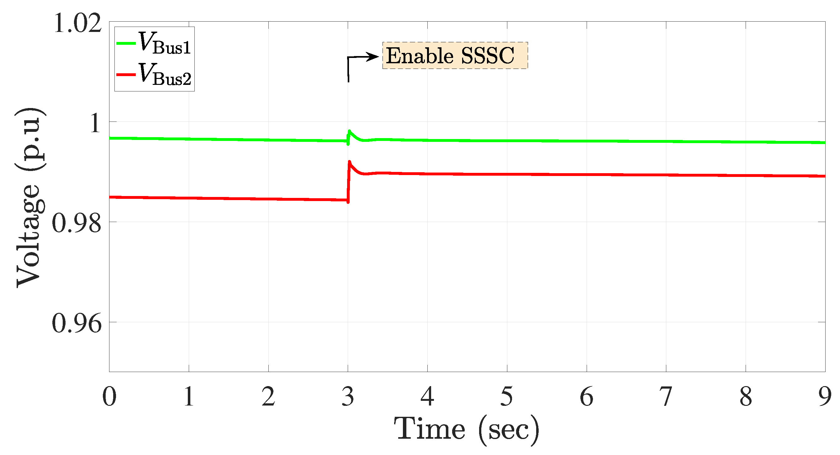
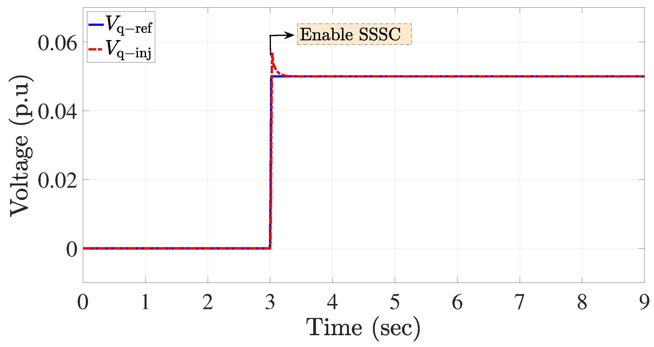
4.1. Case 1: Integrating the SSSC into a Two-Bus Transmission System

Figure 7 illustrates the block diagram of the SSSC connected to the two-bus transmission system. The case study is simulated using MATLAB/Simulink. This case study aims to demonstrate the impact of incorporating the SSSC into one of the transmission lines on the power flow in a two-bus system. To relate this example to the Syrian electricity grid, we consider a real two-bus system that connects Deir-Ali station and Al-Kiswa Bus over a distance of 50 km. At bus 1, the nominal power of the synchronous generator is set to 1730 MVA, representing the power generation station at Deir Ali. The load is connected to Bus 2, with values P Load = 274 MW and Q Load = 68.3 MVar.
The SSSC is connected to Bus 2 at the end of the first transmission line. The detailed control diagram of the SSSC is shown in Figure 4. The DC link voltage of the SSSC inverter is 40 kV, and the capacitors have a value of 375 uF. The reference value of the injection voltage, V q ref , is set to 5% of the nominal voltage of the network to shift nearly 100 MVA. The simulation duration is set to 9 s. Initially, the system operates in a steady state without the SSSC. At 3 s, the SSSC is enabled. Figure 8, Figure 9 and Figure 10 present the results obtained for this case study.
Figure 8a,b show the active and reactive power flow, respectively. As shown in Figure 8a, for t < 3 s, the transmitted active power by lines 2 and 3 are equal, P Line 2 = P Line 3 = 132.8 MW. Hence, the total transmitted active power is P Line 1 = 266 MW. Similarly, Figure 8b shows that for t < 3 s, the transmitted reactive power by lines 2 and 3 are equal, Q Line 2 = Q Line 3 = 33.1 MVar for each line. Hence, the total transmitted reactive power is Q Line 1 = 55.9 MW. It is worth noting that the delivered power is not equal to the desired load due to the termination losses. Upon enabling the SSSC at t 3 s, which is connected to Line 2, it can be seen that the shifted active power is almost 90 MW, where P Line 2 increases from 132.8 MW to almost 222.5 MW. Simultaneously, the transmitted active power by Line 3 decreases to 45.7 MW to compensate for the shifted active power, resulting in the total load active power remaining almost the same at 269 MW. It is worth noting that the reactive power transmitted by both lines is equal and increases after enabling the SSSC for t 3 s.
Figure 9 depicts the voltages of Buses 1 and 2 before and after enabling the SSSC for t < 3 s. It can be observed that the voltage of Bus 1 remains almost the same before and after inserting the SSSC, at about V bus 1 = 0.996 p.u. However, the voltage of Bus 2 changes after inserting the SSSC, increasing from approximately V bus 1 = 0.984 p.u. to almost V bus 1 = 0.990 p.u. Finally, Figure 10 shows the response of the SSSC and its ability to track the voltage reference V q ref , which is set to 5% of the nominal voltage of the network t 3 s.
In summary, this case study clearly demonstrates that the incorporation of the SSSC facilitates power flow control between transmission lines. As a result, it offers the solution for enhancing transmission line capacity without the necessity of constructing new lines.

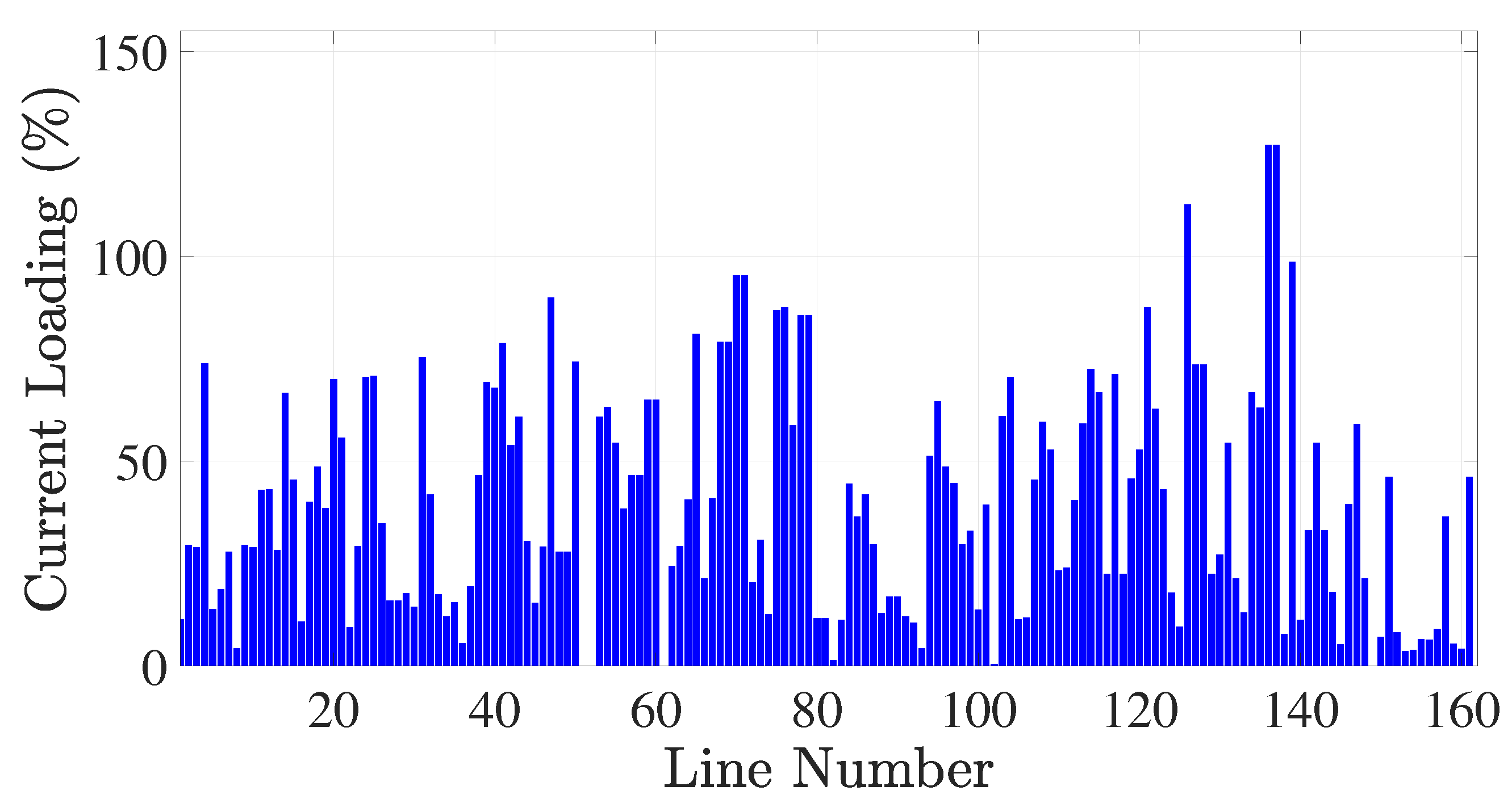
4.2. Case 2: Overloading before Adding SSSCs to the Syrian Electrical Network

In this case study, an investigation is conducted on the power flow of the Syrian electricity grid prior to integrating the SSSC. As mentioned in Section 2, the operational scenario being investigated represents a snapshot of the system at a specific operating point when some of the transmission lines are overloaded. The network, incorporating power stations with capacities as outlined in Table 1, is modeled.
The results obtained from this analysis, specifically the current loading of the transmission lines before the inclusion of the SSSC, are illustrated in Figure 11. These results draw attention to the presence of overloading in certain transmission lines. For example, lines numbered 126, 136, and 137 are found to be overloaded, exceeding 115%, 125%, and 125%, respectively. Such overloading surpasses the thermal limits of these transmission lines, thus compromising the reliability of the network.

4.3. Case 3: Enhancing Loadability of the Syrian Electrical Network via SSSCs

The enhancement of loadability in the Syrian electrical network via the SSSCs is discussed in this section. Initially, the optimal placement of SSSCs is addressed through the utilization of the PSO algorithm, yielding the achievement of the lowest possible active power loss value. Then, the results are presented to showcase the improvement in loadability of the Syrian electrical network through the deployment of SSSC units, aimed at avoiding overloading and consequently leading to an enhancement in the overall performance of the Syrian transmission network.

4.3.1. Optimal Sizing and Allocation of SSSCs for the Syrian Electrical Network

In the investigation of the snapshot operation of the Syrian electrical network, an examination is conducted on optimal sizing and allocation of the SSSC units aiming to enhance the network loadability. The load flow analysis is carried out based on the existing design structure of the network. Subsequent attention is given to the placement of SSSC units with the objective of minimizing active power losses via varying the number of the identical SSSC units and the kVar size of each individual SSSC unit. The data presented in Table 2 displays a performance comparison of three algorithms utilized for the sizing and allocation of the SSSC units. Besides the PSO, two algorithms, namely Genetic Algorithm (GA), and Firefly Algorithm (FFA), are employed.
It is evident that, among the three algorithms compared, the minimum achievable active power loss value is achieved by the PSO algorithm. The optimal solution, determined by the PSO algorithm and comprising the quantity (10) and capacity (1200 kVar) of the SSSC units, clearly demonstrates its efficacy in optimizing performance and facilitating efficient energy transmission (enhancing loadability) within the Syrian electrical network. For instance, the power flow analysis reveals that electrical losses, totaling 7.64% without compensation, are notably reduced to 3.65% through the proposed solution of optimal size and allocation of the SSSCs.
Table 3 provides more details about the parameters employed in the PSO algorithm; for a deeper understanding of these parameters, please refer to [30]. Table 4 presents the results obtained of the optimal sizing and allocation of the SSSCs. These results highlight the recommended locations for installing the SSSCs (locations of the 10 identical SSSCs, each with a capacity of 1200 kVar) in the Syrian electrical network.

4.3.2. Cost Comparison: New Transmission Line vs. SSSCs Deployment

In the examination of cost considerations, an economic comparison is made between the cost implications of constructing a new 230 kV transmission line and the deployment of SSSCs [31]. The cost of a 230 kV transmission line is determined to be USD 1000/MW-mile, resulting in a total expenditure of USD 20 million for a 200 MW capacity transmission line spanning 100 miles. Conversely, a cost analysis for a 100 MVA SSSC is conducted, with a pricing of USD 60/kVar, resulting in a total cost of USD 6 million.
Hence, in the context of SSSC controller installation, a transmission capacity increase of 40% is achieved when applied to a transmission line with a capacity of 200 MW. This results in an added transmission capacity of 80 MW, incurring a cost of USD 6 million. In contrast, the construction of a new transmission line requires an investment of USD 8 million. Consequently, the deployment of SSSCs is deemed to present a cost-saving advantage of USD 2 million in comparison to the construction of a new transmission line.

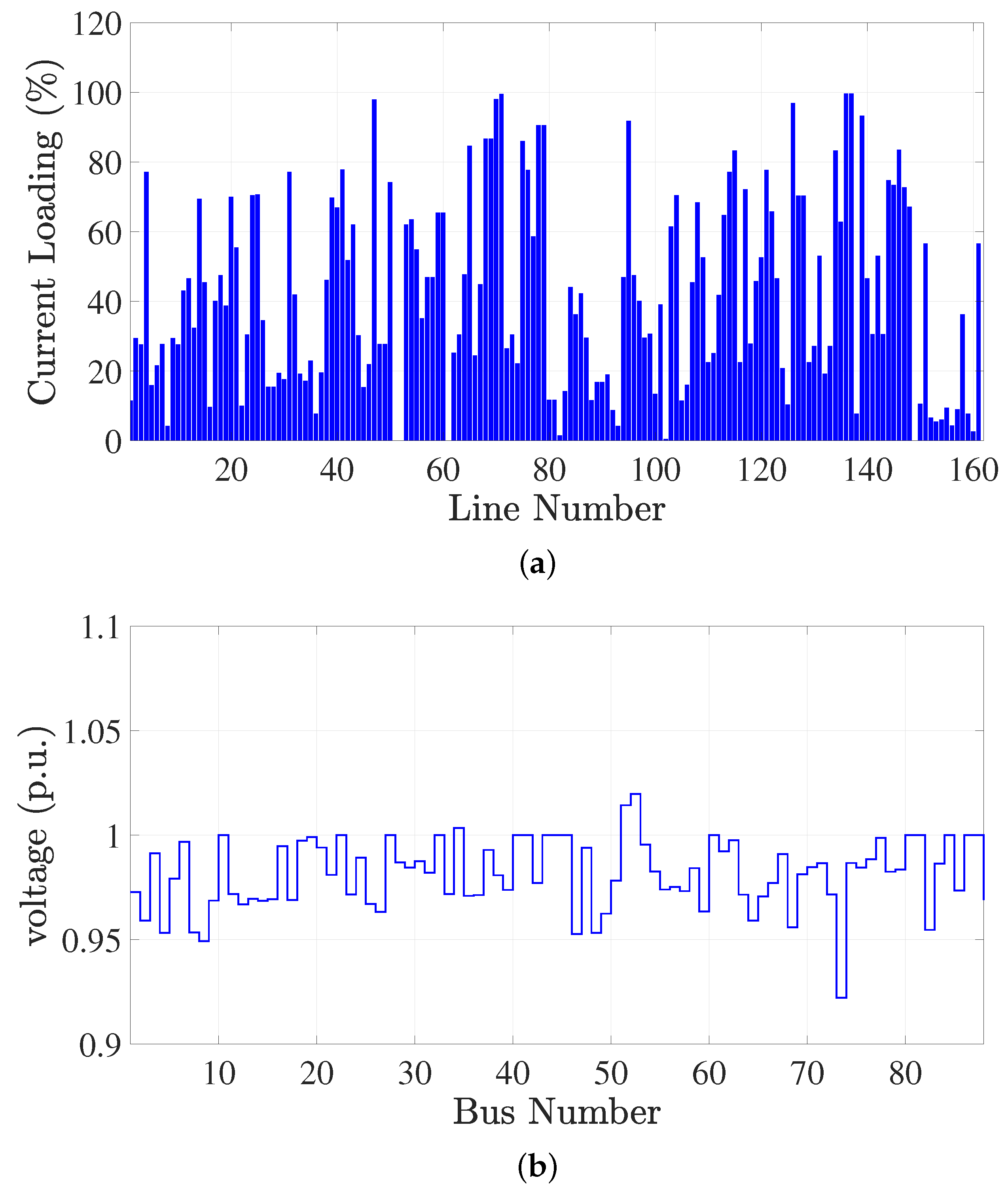
4.3.3. Performance of the Syrian Electrical Network after Adding the SSSCs

In contrast to Case 2, where the power flow analysis was conducted without considering the SSSC, this case study explores the integration of 10 SSSCs into the Syrian electrical network. The optimal sizing and allocation of these SSSCs within the network is achieved using the PSO algorithm as listed in Table 2, Table 3 and Table 4. The voltage reference for the SSSCs, denoted as V q ref , is set to 0.05 p.u.
Figure 12a,b illustrate the current loading of the transmission lines and the voltages at the buses, respectively, after incorporating the SSSCs. It is evident that the integration of SSSCs enhances the loadability of the Syrian electrical network. For instance, all three previously overloaded lines in Case 2 now comply with the thermal limits, with the transported current remaining within the rated values. Additionally, the upper and lower voltage magnitudes across the network buses are within the acceptable ranges of +5% and −10%, respectively. Consequently, the successful resolution of the overloading issue in the Syrian electrical network not only significantly enhances its reliability but also eliminates the necessity of constructing new transmission lines. By effectively preventing violations of the thermal limits in the existing lines, the proposed solution proves to be a cost-effective and straightforward approach, offering distinct advantages.

5. Conclusions

The deployment of SSSC technology is proposed in this paper to alleviate overloading on the Syrian network, with a specific focus on overloaded 230 kV and 400 kV transmission lines. Through the strategic placement of SSSCs on these lines, transmitted power is effectively managed, ensuring reliable power delivery and mitigating line overloading events. The contributions of this paper include an accurate modeling of the Syrian network based on real data and the enhancement of transmission line loadability. The optimal sizing and allocation of the SSSC units are achieved using the PSO algorithm by minimizing active power losses, thereby maximizing the benefits of these compensating devices. The implementation of SSSCs demonstrates significant reductions in loads on critically overloaded lines, enhancing network loadability and providing a practical and efficient solution to address grid reliability challenges.
The investigation undertaken in this paper involves the consideration of a snapshot (one operating point) of the Syrian electrical network. The network overloading is examined, followed by the optimal sizing and allocation of the SSSC units, specifically tailored for this operating point, with the aim of enhancing the network loadability. A potential future research avenue could contribute to a more comprehensive methodology by considering multiple snapshots (e.g., a 24 h window) of the system, thereby enhancing the overall effectiveness of sizing and allocating SSSC units in power systems.

Author Contributions

Conceptualization, H.A., F.S. and T.K.; Methodology, H.A. and N.M.; Software, H.A. and N.M.; Validation, H.A. and N.M.; Formal analysis, H.A., F.S., T.K. and N.M.; Investigation, H.A. and N.M.; Data curation, H.A.; Writing—original draft, H.A. and N.M.; Writing—review & editing, H.A., F.S., T.K. and N.M.; Visualization, H.A. and N.M.; Supervision, F.S. and T.K.; Project administration, F.S. and T.K. All authors have read and agreed to the published version of the manuscript.

Funding

This research received no external funding.

Data Availability Statement

Data are contained within the article.

Conflicts of Interest

The authors declare no conflict of interest.

References

  1. Transformation, G.E. Global Energy Transformation: A Roadmap to 2050; IRENA: Abu Dhabi, United Arab Emirates, 2018. [Google Scholar]
  2. Lopes, J.P.; Hatziargyriou, N.; Mutale, J.; Djapic, P.; Jenkins, N. Integrating distributed generation into electric power systems: A review of drivers, challenges and opportunities. Electr. Power Syst. Res. 2007, 77, 1189–1203. [Google Scholar] [CrossRef]
  3. Amani, A.M.; Jalili, M. Power grids as complex networks: Resilience and reliability analysis. IEEE Access 2021, 9, 119010–119031. [Google Scholar] [CrossRef]
  4. Hingorani, N.G.; Gyugyi, L. Understanding FACTS: Concepts and Technology of Flexible AC Transmission Systems; Wiley-IEEE Press: Hoboken, NJ, USA, 2000. [Google Scholar]
  5. Hamache, A.; Bensidhoum, M.; Ouslimani, A. UPFC Power Flow Tracking using Decentralized Discrete-Time Quasi-Sliding Mode Control. In Proceedings of the 2019 8th International Conference on Systems and Control (ICSC), Marrakesh, Morocco, 23–25 October 2019; pp. 164–169. [Google Scholar]
  6. Yang, D.; Chou, H.M.; Thomas, K.; Kynev, S.; Rye, R. STATCOM Performance Evaluation Using Operation Data from Digital Fault Recorder. In Proceedings of the 2019 IEEE Power & Energy Society General Meeting (PESGM), Atlanta, GA, USA, 4–8 August 2019; pp. 1–5. [Google Scholar]
  7. Venkateswarlu, S.; Velpula, S.; Janaki, M.; Thirumalaivasan, R. Analysis of SSR with SSSC using FPA based Voltage Controller. In Proceedings of the 2019 Innovations in Power and Advanced Computing Technologies (i-PACT), Vellore, India, 22–23 March 2019; Volume 1, pp. 1–6. [Google Scholar]
  8. Rinat, K.R.; Oleg, K.N. Determination of tuning parameters of SVC controllers using D-decomposition method. In Proceedings of the 2020 21st International Symposium on Electrical Apparatus & Technologies (SIELA), Bourgas, Bulgaria, 3–6 June 2020; pp. 1–4. [Google Scholar]
  9. Sen, K.K. SSSC-static synchronous series compensator: Theory, modeling, and application. IEEE Trans. Power Deliv. 1998, 13, 241–246. [Google Scholar] [CrossRef]
  10. Rao, H.G.; Prabhu, N.; Mala, R. Adaptive distance protection for transmission lines incorporating SSSC with energy storage device. IEEE Access 2020, 8, 156017–156026. [Google Scholar] [CrossRef]
  11. Golov, V.; Kormilicyn, D.; Churkina, Y. Controlled Series Compensation Law of Control Selection Procedure. In Proceedings of the 2019 International Conference on Industrial Engineering, Applications and Manufacturing (ICIEAM), Sochi, Russia, 25–29 March 2019; pp. 1–6. [Google Scholar]
  12. Zhang, X.P. Advanced modeling of the multicontrol functional static synchronous series compensator (SSSC) in Newton power flow. IEEE Trans. Power Syst. 2003, 18, 1410–1416. [Google Scholar] [CrossRef]
  13. Barik, S.K.; Mohapatra, S.K.; Patra, A.K. Application of MOL algorithm for SSSC based damping controller design with modified local input signal. In Proceedings of the 2018 Technologies for Smart-City Energy Security and Power (ICSESP), Bhubaneswar, India, 28–30 March 2018; pp. 1–6. [Google Scholar]
  14. Lone, A.H.; Yousuf, V.; Prakash, S.; Bazaz, M.A. Load frequency control of two area interconnected power system using SSSC with PID, Fuzzy and Neural Network Based Controllers. In Proceedings of the 2018 2nd IEEE International Conference on Power Electronics, Intelligent Control and Energy Systems (ICPEICES), Delhi, India, 22–24 October 2018; pp. 108–113. [Google Scholar]
  15. Fadhil, S.T.; Vural, A.M. Comparison of dynamic performances of TCSC, Statcom, SSSC on inter-area oscillations. In Proceedings of the 2018 5th International conference on electrical and electronic engineering (ICEEE), Istanbul, Turkey, 3–5 May 2018; pp. 138–142. [Google Scholar]
  16. Wang, X.; Wu, D.; Wei, M.; Li, J.; Wang, H.; Li, Q. The capacitor voltage balancing control strategy based on hierarchical theory in Cascaded H-bridge SSSC. In Proceedings of the 2018 IEEE 2nd International Electrical and Energy Conference (CIEEC), Beijing, China, 4–6 November 2018; pp. 40–44. [Google Scholar]
  17. Kumar, L.S.; Ghosh, A. Modeling and control design of a static synchronous series compensator. IEEE Trans. Power Deliv. 1999, 14, 1448–1453. [Google Scholar] [CrossRef]
  18. Rashitov, P.A.; Vershanskiy, E.A.; Gorchakov, A.V. The Techniques of Reactance Regulation by the Distributed Static Synchronous Series Compensator in Power Lines. In Proceedings of the 2019 20th International Conference of Young Specialists on Micro/Nanotechnologies and Electron Devices (EDM), Erlagol, Russia, 29 June–3 July 2019; pp. 469–475. [Google Scholar]
  19. Gu, L.; Zhou, X.; Liu, M.; Shi, H. Nonlinear control of SSSC for power system stability enhancement. In Proceedings of the 2010 International Conference on Power System Technology, Zhejiang, China, 24–28 October 2010; pp. 1–6. [Google Scholar]
  20. Farahani, M.; Ganjefar, S.; Alizadeh, M. Intelligent control of SSSC via an online self-tuning PID to damp the subsynchronous oscillations. In Proceedings of the 20th Iranian Conference on Electrical Engineering (ICEE2012), Tehran, Iran, 15–17 May 2012; pp. 336–341. [Google Scholar]
  21. Bagha, G.; Kumar, A. Voltage profile enhancement for IEEE-14 bus system using UPFC, TCSC and SSSC. In Proceedings of the 2018 2nd IEEE International Conference on Power Electronics, Intelligent Control and Energy Systems (ICPEICES), Delhi, India, 22–24 October 2018; pp. 267–272. [Google Scholar]
  22. Pandey, R.; Chaitanya, D. An effective approach for ATC enhancement with FACTS device-A case study. In Proceedings of the 2012 International Conference on Advances in Power Conversion and Energy Technologies (APCET), Mylavaram, India, 2–4 August 2012; pp. 1–6. [Google Scholar]
  23. BV, A.; AO, E. Enhancing Loadability of Transmission Lines Using Series Compensation (Facts) Device in Nigeria Network. Iconic Res. Eng. J. 2018, 2, 12–22. [Google Scholar]
  24. Gyugyi, L.; Edris, A.A.; Eremia, M. Static synchronous series compensator (SSSC). In Advanced Solutions in Power Systems: HVDC, FACTS, and Artificial Intelligence: HVDC, FACTS, and Artificial Intelligence; Wiley: Hoboken, NJ, USA, 2016; pp. 527–557. [Google Scholar]
  25. Gandhar, S.; Ohri, J.; Singh, M. Application of SSSC for compensation assessment of interconnected power system. In Proceedings of the 2014 IEEE 6th India International Conference on Power Electronics (IICPE), Kurukshetra, India, 8–10 December 2014; pp. 1–5. [Google Scholar]
  26. Divan, D.; Johal, H. Distributed FACTS-A new concept for realizing grid power flow control. In Proceedings of the 2005 IEEE 36th Power Electronics Specialists Conference, Dresden, Germany, 16 June 2005; pp. 8–14. [Google Scholar]
  27. Dahat, S.A.; Dhabale, A. Co-ordinated Control of Combination of SSSC and SVC for Enhancement of Power System Voltage Stability. In Proceedings of the 2022 IEEE International Conference on Power Electronics, Smart Grid, and Renewable Energy (PESGRE), Trivandrum, India, 2–5 January 2022; pp. 1–6. [Google Scholar]
  28. Mohammed, N.; Ciobotaru, M. Adaptive power control strategy for smart droop-based grid-connected inverters. IEEE Trans. Smart Grid 2022, 13, 2075–2085. [Google Scholar] [CrossRef]
  29. Saadat, H. Power System Analysis; McGraw-Hill: New York, NY, USA, 1999; Volume 2. [Google Scholar]
  30. Eberhart, R.; Kennedy, J. A new optimizer using particle swarm theory. In Proceedings of the MHS’95, Sixth International Symposium on Micro Machine and Human Science, Nagoya, Japan, 4–6 October 1995; pp. 39–43. [Google Scholar]
  31. Baldick, R.; O’Neill, R.P. Estimates of comparative costs for uprating transmission capacity. IEEE Trans. Power Deliv. 2009, 24, 961–969. [Google Scholar] [CrossRef]
Figure 1. The geographical distribution of the power stations throughout Syria.
Energies 17 00390 g001
Figure 2. Single line diagram shows part of the Syrian grid including the overloaded transmission lines between Dear-Ali and Al-Kiswa power stations.
Energies 17 00390 g002
Figure 3. Integration of the statistic synchronous series compensator to the transmission lines.
Energies 17 00390 g003
Figure 4. Closed-loop control of the statistic synchronous series compensator.
Energies 17 00390 g004
Figure 5. Power flow through a two-bus transmission line.
Energies 17 00390 g005
Figure 6. Proposed Flowchart of the PSO algorithm used for optimal sizing and allocation of SSSCs.
Energies 17 00390 g006
Figure 7. The simulated circuit in MATLAB/Simulink to investigate the impacts of integrating the SSSC into a two-bus transmission system (Deir-Ali with Al-Kiswa stations).
Energies 17 00390 g007
Figure 8. Power flow in transmission lines of the two-bus system before and after enabling the SSSC at t 3 s with V q ref = 5 % of the network nominal voltage: (a) Active power, (b) reactive power.
Energies 17 00390 g008
Figure 9. Voltages of the two-bus system before and after enabling the SSSC at t 3 s with V q ref = 5 % of the network nominal voltage.
Energies 17 00390 g009
Figure 10. Measured and reference voltage of the SSSC.
Energies 17 00390 g010
Figure 11. Current loadings of 230 kV and 400 kV transmission lines in the Syrian network before incorporating SSSCs.
Energies 17 00390 g011
Figure 12. Load condition of the 230 kV and 400 kV transmission lines in the Syrian network after incorporation of the SSSCs: (a) Current loadings, (b) voltage magnitudes.
Energies 17 00390 g012
Table 1. Capacities of existing power stations in the Syrian electrical network.
Station NameNominal Capacity (MW)Station NameNominal Capacity (MW)
Deir Ali1370Jandar600
Aleppo1150Mehardeh530
Banias940Nasserieh480
Tishreen Dam820Zayzoun384
Tishreen820Swediah170
Al-Thawrah700Thayyem100
Al-Zara660Baath50
Table 2. Performance comparison of different algorithms used for the sizing and allocation of the SSSC units.
AlgorithmNo. of SSSC UnitsSize of Each SSSC UnitActive Power Losses
GA95.07%1330
FFA124.24%1000
PSO103.65%1200
Table 3. Parameters used for the PSO algorithm.
VariableCase 1Case 2
Number of Samples250500
Number of Iterations60100
C122
C222
W11
Table 4. PSO algorithm-based results: optimal locations and associated reactive power values (size) of the SSSCs in the Syrian electricity grid.
BusesVolume (kVar)BusesVolume (kVar)
101200751200
121200421200
721200231200
791200331200
181200841200
Disclaimer/Publisher’s Note: The statements, opinions and data contained in all publications are solely those of the individual author(s) and contributor(s) and not of MDPI and/or the editor(s). MDPI and/or the editor(s) disclaim responsibility for any injury to people or property resulting from any ideas, methods, instructions or products referred to in the content.

