Article

Enhancing Heat Storage Cooling Systems via the Implementation of Honeycomb-Inspired Design: Investigating Efficiency and Performance

Department of Engineering, University of Exeter, Exeter EX4 4QF, UK
*
Author to whom correspondence should be addressed.
Energies 2024, 17(2), 351; https://doi.org/10.3390/en17020351
Submission received: 15 November 2023 / Revised: 4 December 2023 / Accepted: 11 December 2023 / Published: 10 January 2024
(This article belongs to the Section D: Energy Storage and Application)

Abstract

:
This study presents a novel approach inspired by the hexagonal honeycomb structure found in nature, leveraging image processing algorithms to precisely define complex geometries in thermal systems. Hexagonal phase change material containers and thermally conductive fins were meticulously delineated, mirroring the intricate real-world designs of honeycombs. This innovative methodology not only streamlines setup processes but also enhances our understanding of melting dynamics within enclosures, highlighting the potential benefits of biomimetic design principles in engineering applications. Two distinct honeycomb structures were employed to investigate their impact on the melting process within cavities subject to heating from the left wall, with the remaining walls treated as adiabatic surfaces. The incorporation of a thermally conductive fin system within the enclosure significantly reduced the time required for a complete phase change, emphasizing the profound influence of fin systems on thermal design and performance. This enhancement in heat transfer dynamics makes fin systems advantageous for applications prioritizing precise temperature control and expedited phase change processes. Furthermore, the critical role of the fin system design was emphasized, influencing both the onset and location of the final point of melting. This underscores the importance of tailoring fin systems to specific applications to optimize their performance. Our study highlights the significant impact of the Rayleigh (Ra) number on the melting time in a cavity without fins, revealing a decrease from 6 to 0.4 as the Ra increased from 102 to 105; the introduction of a fin system uniformly reduced the melting time to Ste.Fo = 0.5, indicating fins’ universal effectiveness in optimizing thermal dynamics and expediting the melting process. Moreover, the cavity angle was found to significantly affect the fluid fraction diagram in unfanned cavities but had minimal impact when fins were present, highlighting the stabilizing role of fins in mitigating gravitational effects during melting processes. These insights expand our understanding of cavity geometry and fin interactions in heat transfer, offering potential for enhanced thermal system designs in various engineering applications. Decreasing thermal conductivity (λ) by increasing the fin thickness can halve the melting time, but the accompanying disadvantages include a heavier system and reduced energy storage due to less phase change material, necessitating a careful balance in decision-making.

1. Introduction

Due to their distinct ability to store and release thermal energy during phase transitions, phase change materials (PCMs) play a critical role in modern heat storage systems [1]. PCMs offer an efficient means of managing and optimizing thermal energy storage as the demand for energy rises and sustainable solutions become imperative [2]. PCMs maintain a constant temperature within a predetermined range by accumulating heat during the phase change from solid to liquid and releasing it during the reversal [3]. This capability is especially useful in applications such as solar thermal systems [4], where PCMs can store excess solar energy during the day and discharge it during the night when temperatures drop. PCMs also improve energy efficiency by reducing temperature fluctuations [5] and preventing overheating [6] or refrigeration [7], thereby extending equipment life [8] and reducing energy consumption [9]. PCMs are crucial to the development of sustainable heat storage solutions for a greener future due to their adaptability to various environments, simplicity of integration, and potential for use with renewable energy sources [10].
Simulation methods have emerged as indispensable instruments for optimizing the performance of PCM-based systems and gaining a deeper understanding of their operation [11]. These simulation techniques enable scientists and engineers to model and analyze the intricate heat transfer and phase change phenomena that occur in PCM systems. Utilizing computational methods such as the Finite Volume Method (FVM) [12], Molecular Dynamics (MD) [13], and lattice Boltzmann method (LBM) [14], researchers are able to investigate the thermal behavior, transient responses, and overall efficacy of PCM-based systems under different conditions.
Numerous scholars have investigated different geometries in recent years to model the effects of phase change materials (PCMs) in various engineering applications using computational fluid dynamics (CFD) [15,16,17,18,19,20]. CFD approaches provide a potent tool for deciphering intricate heat and mass transport processes in PCM systems, and they are often applied using commercial software platforms like ANSYS CFD and COMSOL Multiphysics [21]. These studies include a broad variety of topics, such as energy storage [22], improved heat transport, thermal management [23], and more. Researchers are working to improve the performance of PCMs by using various geometries, including finned structures [24], enclosed containers [25], and composite materials [26].
The lattice Boltzmann method (LBM) has emerged as a versatile and powerful numerical technique for simulating complex fluid flow and heat transfer phenomena, making it a valuable tool in studying phase change material (PCM) melting and their interactions with various factors [27]. The LBM has distinct advantages when it comes to capturing intricate fluid–solid phase transitions, and it is well suited to dealing with complex geometries [28] and boundary conditions [29]. This method allows for a thorough examination of the dynamic interactions between fluid flow, heat transfer, and phase change phenomena in PCM systems. The LBM’s distinct capabilities make it an essential approach for understanding the underlying mechanisms governing PCM melting processes and optimizing their use in a wide range of engineering applications.
The work by Huber et al. [30] introduces a pioneering lattice Boltzmann method that offers a fresh perspective on the intricate interplay between thermal convection and the melting process of pure substances. Their innovative approach adeptly captures the nuanced shift from heat transfer being primarily driven by conduction to the emergence of fully developed convection.
Wang et al. [31] introduced an innovative lattice Boltzmann method (LBM) model that encompasses a novel equilibrium distribution function. This pioneering approach enabled them to effectively solve complex two-dimensional (2D) and three-dimensional (3D) geometries associated with phase change phenomena.
Wei and Karimi [32] conducted a study using the lattice Boltzmann method (LBM) to investigate the impact of nanoparticles and expanded fins on the simulation of phase change material (PCM) behavior in a thermal storage device. Their findings indicated that the addition of nanoparticles, ranging from 0% to 3%, led to a decrease in the melting time. Similarly, increasing the number of fins in the system produced a similar outcome, highlighting the potential for enhanced heat transfer and accelerated melting processes.
Li and Yu [33] employed a three-dimensional lattice Boltzmann method to analyze the impact of fins on the phase change material melting process. They conducted a comprehensive parametric investigation, exploring different fin configurations while maintaining a constant total fin volume. Their study delved into the intricate interplay of fin arrangements with natural convection patterns, melting time, and interface area. Notably, the research highlighted that altering the fin structures could yield enhanced heat transfer rates and improved energy storage capabilities, outperforming the simple strategy of increasing the number of fins.
Addressing the intrinsic limitation of PCMs’ low thermal conductivity presents a considerable challenge in facilitating efficient heat transfer during the melting or solidification phases, consequently affecting the overall efficacy of energy storage solutions. As a response, a diverse array of strategies has emerged to augment the heat transfer capabilities of PCMs. These strategies encompass the utilization of various techniques such as incorporating metal foams [34], integrating nanoparticles [35,36], employing carbon nanotubes [36], introducing additional internal fins [37], as well as exploring the potential benefits of ultrasonic and magnetic fields [38]. These distinct methodologies collectively strive to enhance the heat transfer performance, thereby optimizing the effectiveness of thermal energy storage systems relying on PCMs.
Darzi et al. [39] addressed the low thermal conductivity of PCMs by proposing thermal fins in a cylindrical annulus setup. They investigated the fin geometry, quantity, and nanoparticle integration to enhance heat transfer, offering valuable insights for improved PCM-based thermal management applications.
Ren et al. [40] employed an enthalpy-based LBM model to simulate PCM melting enhanced by nanoparticles and fins. The study found that triangular fins outperformed nanoparticles in accelerating melting. At higher wall temperatures, an increased nanoparticle volume fraction decreased the LHTES energy storage efficiency due to the reduced capacity and heightened PCM viscosity, weakening natural convection. In another study, Ren et al. [41] explored electronic thermal management utilizing PCM-EG composites and pin fins. They extensively optimized the system under various parametric conditions to enhance its performance.
Zhang et al. [42] investigated Latent Heat Thermal Energy Storage (LHTES) systems with varied fin length ratios and no fins. Using a composite PCM of paraffin and copper oxide, they used an enthalpy-based LBM model to simulate phase change. Compared to finless designs, unequal fin lengths reduced the melting times by 16.7% to 33.06%, and solidification times by 47.33% to 57.54%. In terms of the overall heat storage and release, equal-length fins were found more effective.
Alizadeh et al. [43] conducted a numerical investigation on the solidification of a PCM within a hexagonal storage unit. They studied the impact of innovative branching fins and nanoparticles as direct and indirect heat transfer augmentation techniques. The study revealed a 3% reduction in release exergy efficiency when increasing the HTF temperature from 240 K to 260 K. Furthermore, enhancing the amplitude and duration of the cold wall was found to accelerate the solidification process.
Mostafa et al. [44] aimed to enhance the PCM melting efficiency in storage via the use of novel fins, combining rectangular and triangular shapes. They investigated the influence of triangular fin height on the melting rate, and explored the effects of various storage hot wall temperatures and PCM materials on the process.
Rapid PCM melting is crucial for applications like thermal energy storage, electronics cooling, and ice/snow removal. Fins enhance the heat transfer efficiency, crucial for quick melting, by increasing the surface area and promoting uniform heat distribution within the PCM material, benefiting systems requiring a swift phase change.
Honeycomb structures are advantageous in heat transfer due to their high surface-area-to-volume ratio, promoting efficient heat exchange and enhanced convection. They offer reduced weight, structural integrity, and uniform heat distribution, making them suitable for applications requiring both optimal thermal performance and structural support. Honeycomb structures also act as effective heat shields, offer low pressure drop, and improve the heat exchanger efficiency by facilitating convective heat transfer and large surface areas for fluid interaction. Additionally, they can provide acoustic damping properties. Overall, honeycomb structures offer a versatile solution for various heat transfer applications, including aerospace, automotive, electronics cooling, and thermal management.
Introducing a novel approach, this study draws inspiration from the hexagonal honeycomb structure seen in nature to enhance our proposed thermal system. We employ image processing algorithms to precisely define complex geometries, such as hexagonal phase change material (PCM) containers and thermally conductive fins, simulating intricate real-world designs. This innovative methodology not only streamlines the setup process but also contributes to a deeper understanding of the melting process within the enclosure, showcasing the potential benefits of biomimetic design principles in engineering applications.
In this research paper, our primary objective is to comprehensively explore the influence of hexagonal honeycomb structure fins on the phase change material (PCM) melting process. To achieve this goal, we have organized the paper into distinct sections to facilitate a clear and coherent presentation of our study. Commencing with a comprehensive background section, we provide the necessary context and foundational information relevant to our investigation. Following this, we delve into a detailed exposition of our methodology, elucidating the approach and techniques employed in our experimental design. The subsequent sections of the paper are dedicated to presenting the results obtained and conducting a thorough analysis of the data. Finally, we encapsulate our findings with a concluding section that not only summarizes the key outcomes but also engages in a thoughtful discussion regarding the broader implications and significance of our research within the relevant academic and practical domains.

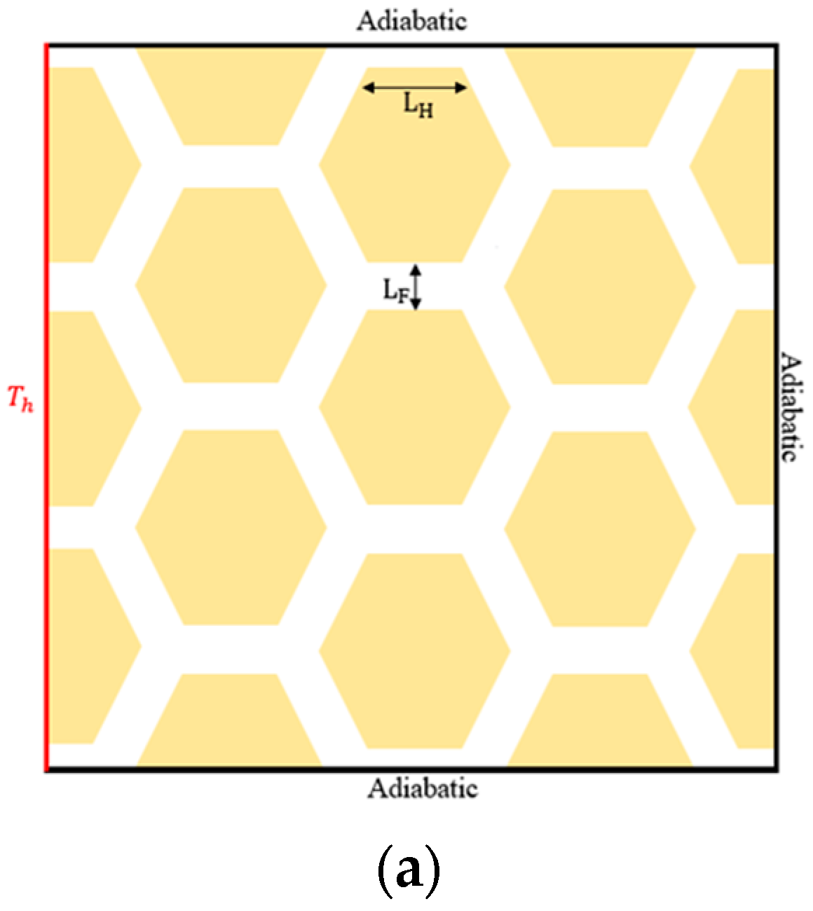
2. Honeycomb Cooling Structure

Geometry

Inspired by bee honeycomb, we adopted a hexagonal structure for our study. The choice is rooted in the inherent benefits demonstrated by hexagonal cells in facilitating smooth movement, efficient use of space, and robust structural support. By emulating nature’s design principles, we aim to enhance the performance of our proposed system.
In this study, two different honeycomb structures are used. In both cases, a hexagonal honeycomb structure is employed to examine its impact on the melting process within a cavity that experiences heating solely from its left wall, while the remaining walls are treated as adiabatic surfaces. Figure 1 illustrate the geometry adopted for this research. The fins in this configuration are presumed to be composed of a thermally conductive metal capable of efficiently distributing heat from the heat source to all regions within the cavity. The hexagonal cells contain PCMs. L H represents the width of the hexagonal cells and L F represents the width of the fins.
To establish the parameters for the honeycomb phase change material (PCM) containers and fins within the newly devised code, an image processing algorithm is employed. This algorithm is designed to distinguish and classify regions within the image, assigning a value of zero to PCM zones and a value of one to solid regions. This technique aids in accurately demarcating the boundaries and characteristics of these components. By incorporating this algorithm, a precise and automated approach is achieved for delineating PCM containers and fins, enhancing the efficiency and accuracy of the overall process. The computer code utilized in this study includes a Python program for image processing algorithms, and FORTRAN code specifically developed for solving the lattice Boltzmann method (LBM) equations.
λ can be defined as the ratio between the PCM space and domain.
λ = S P C M S t o t a l ,
Table 1 displays the thermophysical properties of the phase change material (PCM).

3. Governing Equations

3.1. Lattice Boltzmann Method

The geometry described in Figure 1 and Figure 2 contains two distinct zones which are the PCMs and metal fins, for which Navier–Stokes equations should be solved separately. For the PCM zone, momentum and energy equations should be solved, while for the metal fin zone, only an energy equation should be solved.
The equations for the PCM zone are provided below:
· u * = 0 ,
u * t * + u * · ( · u * ) = p * + P r 2 u * + P r R a β T *
T * t + u * · T * = α 2 T * 1 S t e h l t *
All variables are defined in the nomenclature section. These equations can be recovered using the lattice Boltzmann method. The lattice Boltzmann method (LBM) is a numerical technique widely utilized for simulating complex phenomena at the mesoscale, particularly in fluid dynamics. Employing a kinetic approach based on the Boltzmann equation, the LBM discretizes distribution functions on a regular lattice grid. Notable for its simplicity, scalability, and versatility, the LBM excels in handling large-scale problems via easy parallelization in high-performance computing environments. Its grid-based structure allows for the efficient representation of intricate geometries and irregular boundaries, making it suitable for multiphase flows. Operating at the mesoscale, the LBM proves advantageous for studying phenomena in diverse fields such as materials science, microfluidics, and biological systems. Its accessibility, owing to its straightforward implementation and clear physical interpretation, extends its utility to researchers across various disciplines.
Momentum:
f i x + c i t ,   t + t = f i x , t + t τ υ f i e q x , t f i x , t + Δ t c i F i ,
Energy:
g i x + c i Δ t , t + Δ t = g i x , t + Δ t τ D g i e q x , t g i x , t w i 1 S t e   ( h l n , k h l n 1 ) ,
where:
S t e = c p Δ T L f
To solve these equations, equilibrium distribution functions should be defined.
f i e q = w i ρ 1 + c i · u c s 2 + 1 2 c i · u 2 c s 4 1 2 u 2 c s 2
g i e q x , t = w i T 1 + c i · u c s 2
To recover the N–S equations, τ υ and τ D should be defined as functions of viscosity and thermal diffusivity.
τ υ = 3 ν + 0.5  
τ D = 3 α + 0.5
It is important to emphasize that in the computational framework being utilized, the momentum equation is meticulously solved for employing a D2Q9 lattice structure. In parallel, the energy equation is addressed within the confines of a D2Q5 lattice arrangement. w i and c i are defined as:
c i = 0 1 0 0      0 1 1 0      0 1 1 1      1 1 1 1     1 1
w i = 4 9 1 9 1 9     1 9 1 9 1 36     1 36 1 36 1 36
F i is representative of external forces which apply to the fluid domain such as gravity.
F = F x +   F y = 3 w i ρ g y
g y can be calculated using the definition of the Ra number, which is defined as follows:
R a = g β T h T c H 3 α ν
For an inclined cavity, g = g c o s θ   where θ is the angle of the cavity.
The term w i 1 S t e ( h l n , k h l n 1 ) in the energy equation is added to simulate the PCM melting process, for which a detailed description can be found in Ref. [45]. h l n , k is the fluid fraction at time step n and iteration k in the i direction and can be updated as follows [46]:
f l n , k = 0 E n n , k < E n s = c p T m s o l i d   z o n e E n n , k E n s E n l E n s   E n s E n n , k E n s + L f   m u s h y   z o n e 1 E n n , k > E n s + L f l i q u i d   z o n e
The fluid fraction, ranging from 0 to 1, is determinable based on the enthalpy value, enabling the automated calculation of the PCM front. The local enthalpy at time step n and iteration k can be computed as follows:
E l n , k = c p T n , k + L f h l n , k 1
Solving Equations (6) and (7) will provide us with the opportunity to calculate the density, velocity, and temperature in the geometry using Equations (13)–(15).
ρ = i f i
u j = i f i c i j
T = i g i
In the fin zone, the momentum equation will not be solved. The energy equation in the solid zone is presented in Equation (16):
T * t = α f i n 2 T *
To recover this equation, the following LBM equations are solved:
g i x + c i Δ t , t + Δ t = g i x , t + Δ t τ D g i e q x , t g i x , t
where:
g i e q x , t = w i T
τ D = 3 α f i n + 0.5
Finally, the temperature in the fin area can be found using Equation (20).
T f i n = i g i

3.2. Boundary Conditions

To model the lattice Boltzmann method (LBM) simulation for the phase change material (PCM) melting scenario, significant reliance is placed on the specification of the boundary conditions. The following outlines the boundary conditions employed for momentum and energy considerations.
Momentum:
In this simulation, all walls are considered to be stationary. To impose a no-slip boundary condition on the walls, a bounce-back boundary condition is utilized. Mathematically, this condition is expressed as:
f i x , t = f i ~ x , t
in which i ~ is the opposite direction of i.
Energy:
For the energy equation, it is notable that interaction between the fins and PCMs should not be considered as a boundary because it is an interface wall, and instead two different energy equations should be solved for them. For the hot wall, we have:
g 1 = T h w 1 + w 3 g 3 g 5 = T h w 5 + w 7 g 7 g 8 = T h w 8 + w 6 g 6
And the rest of walls are adiabatic where:
g 6 , n = g 8 , n ,     g 5 , n = g 7 , n ,     g 2 , n = g 4 , n

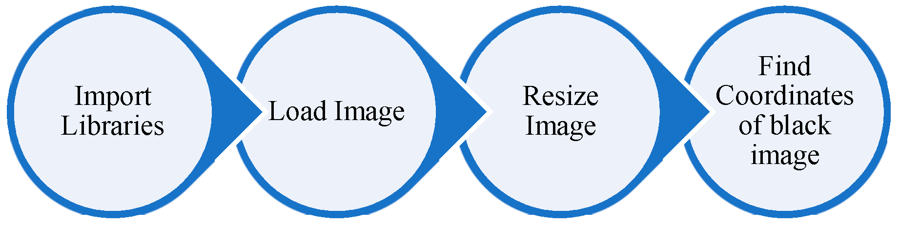
3.3. Image Processing Algorithms
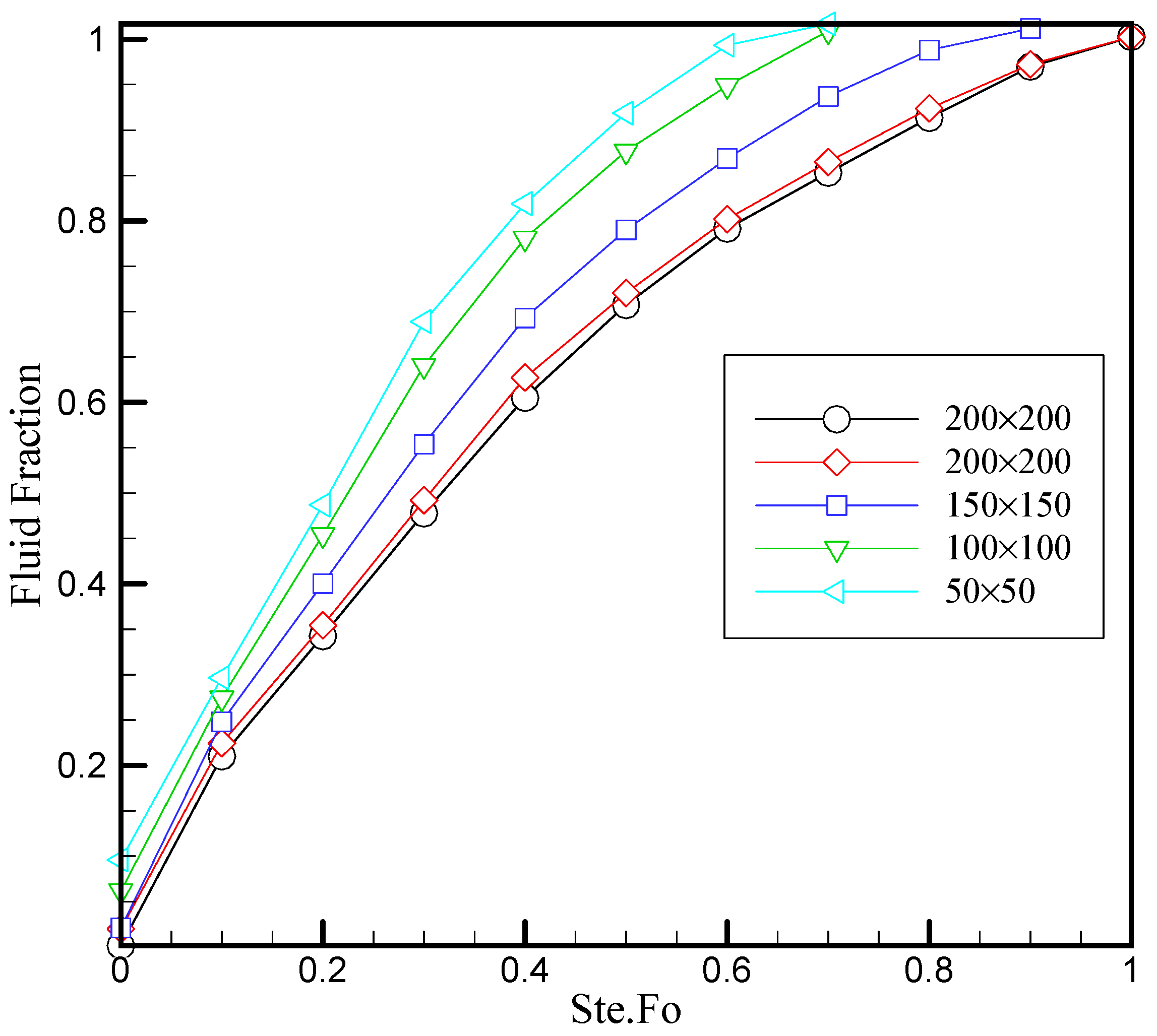
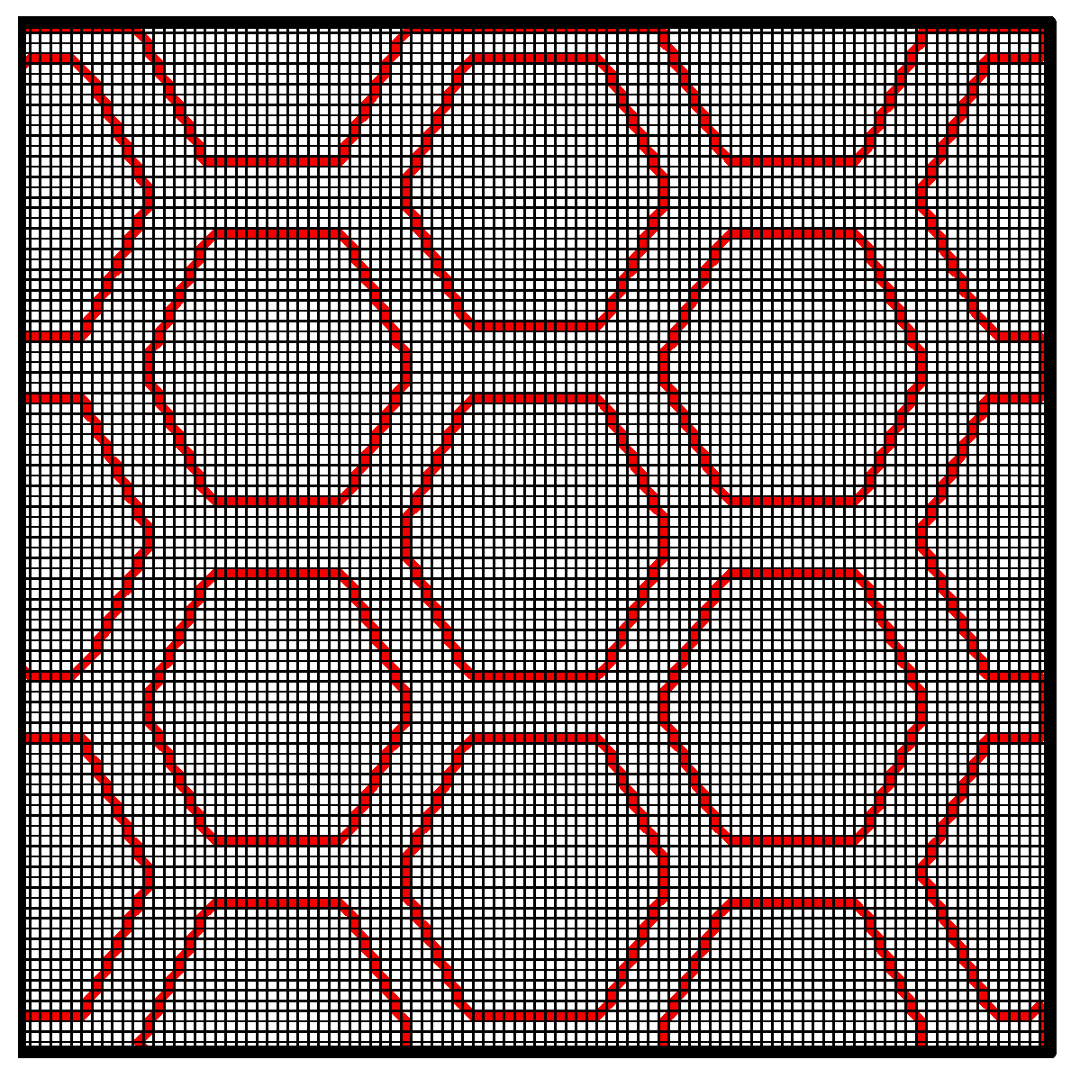
To employ image processing algorithms for importing the geometry into the lattice Boltzmann method (LBM) in Python, the OpenCV library proves to be a valuable tool. This methodology involves preparing an image that represents the fin system, where solid nodes are depicted in black and fluid nodes in white. The algorithm employed in this process typically converts black nodes into the numerical value ‘1’ and white nodes into ‘0’. This binary representation simplifies the subsequent conversion of the image into a matrix. In the next steps of the workflow, this matrix, now representing the spatial distribution of solid and fluid nodes, is utilized in the LBM calculations. The lattice Boltzmann method, often used for fluid dynamics simulations, relies on a lattice-based grid where each node carries information about fluid density and velocity. By leveraging the capabilities of the OpenCV library, the image processing algorithm facilitates the seamless transition from a visual representation of the fin system to a numerical matrix that aligns with the requirements of the LBM. This integration of image processing and numerical simulation techniques plays a crucial role in accurately modeling and simulating fluid flows around complex geometries, such as fin systems, in a computationally efficient manner. The utilization of OpenCV in this context highlights the interdisciplinary nature of computational fluid dynamics, combining expertise in image processing with numerical methods to gain insights into the fluid behavior around intricate geometrical structures. This approach not only enhances the accuracy of simulations but also contributes to the broader field of fluid dynamics research. Figure 2 shows the image processing algorithm.
Figure 2. Image processing algorithm.
Energies 17 00351 g002

4. Grid Study

Based on an evaluation on the fluid fraction, different grid sizes are tested and confirmed to ensure that the solution’s accuracy is not affected by the grid size chosen. As shown in Figure 3, there is a noticeable variation in melt fractions when using grid sizes of 50 × 50, 100 × 100, 150 × 150, 200 × 200, and 250 × 250. However, the largest difference between a 200 × 200 grid and a 250 × 250 grid was reduced to just 2%. Consequently, we decided to use a 200 × 200 grid configuration for this study.
Ste.Fo is defined as a dimensionless time in our study:
t * = S t e . F o = c p Δ T L f × t α H 2
Figure 4 provides a visual representation of the specifically selected grid configuration utilized in case 1, affirming our commitment to an optimal grid size that ensures both computational efficiency and solution accuracy in our simulation endeavors.

5. Validation

A validation study was conducted to assess the accuracy and reliability of newly designed numerical code in simulating the natural convection of phase change materials inside a finned cavity. The isothermal lines at a Rayleigh number (Ra) of 1.7 × 10⁴ are reported in Figure 5 which is compared with the findings of Jourabian et al. [45]. The cavity in this article has been equipped with a metal fin that is attached to the heated wall of the cavity, namely located on the left side wall. The findings demonstrate a high level of concurrence and validate the implemented computer code.
The simulation results for a finned cavity, employing an image processing algorithm, reveal consistent isothermal lines across various lengths of fins at different dimensionless times (Ste.Fo). A comparative analysis is conducted for four distinct cases: the cavity without a fin and three cases with fins of lengths lf = 0.25, 0.5, and 0.75. Notably, a strong agreement is observed in both the melting pattern and the slope of the isothermal lines, underscoring the accuracy of the image processing method in effectively defining the geometrical features of the fins. This robust concurrence across different fin lengths substantiates the reliability and precision of the employed image processing technique in capturing and representing the intricate details of the finned cavity, thereby validating its efficacy for simulations involving phase change materials. In this study, it is worth highlighting the utilization of an image processing algorithm as a novel approach to defining the intricate geometries of fins within the context of lattice Boltzmann method (LBM) simulations. The outcomes of our investigation unequivocally demonstrate that employing an image processing algorithm proves to be an effective and promising methodology for accurately characterizing complex geometrical features in LBM studies.

6. Results

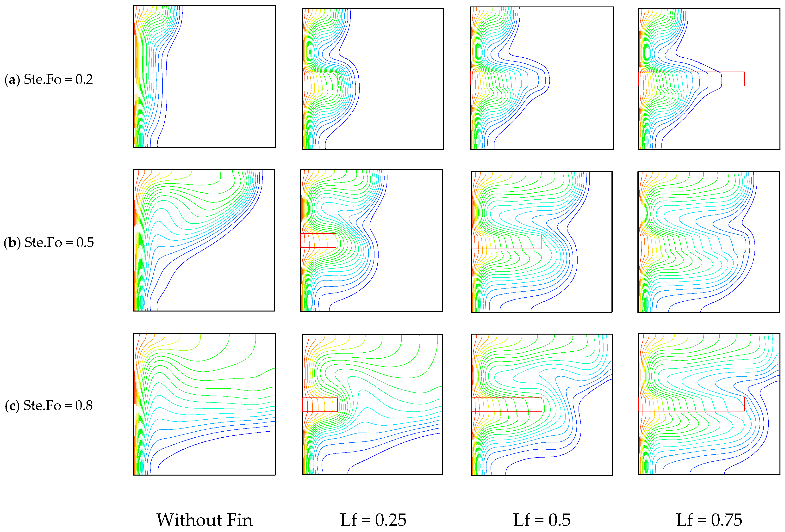
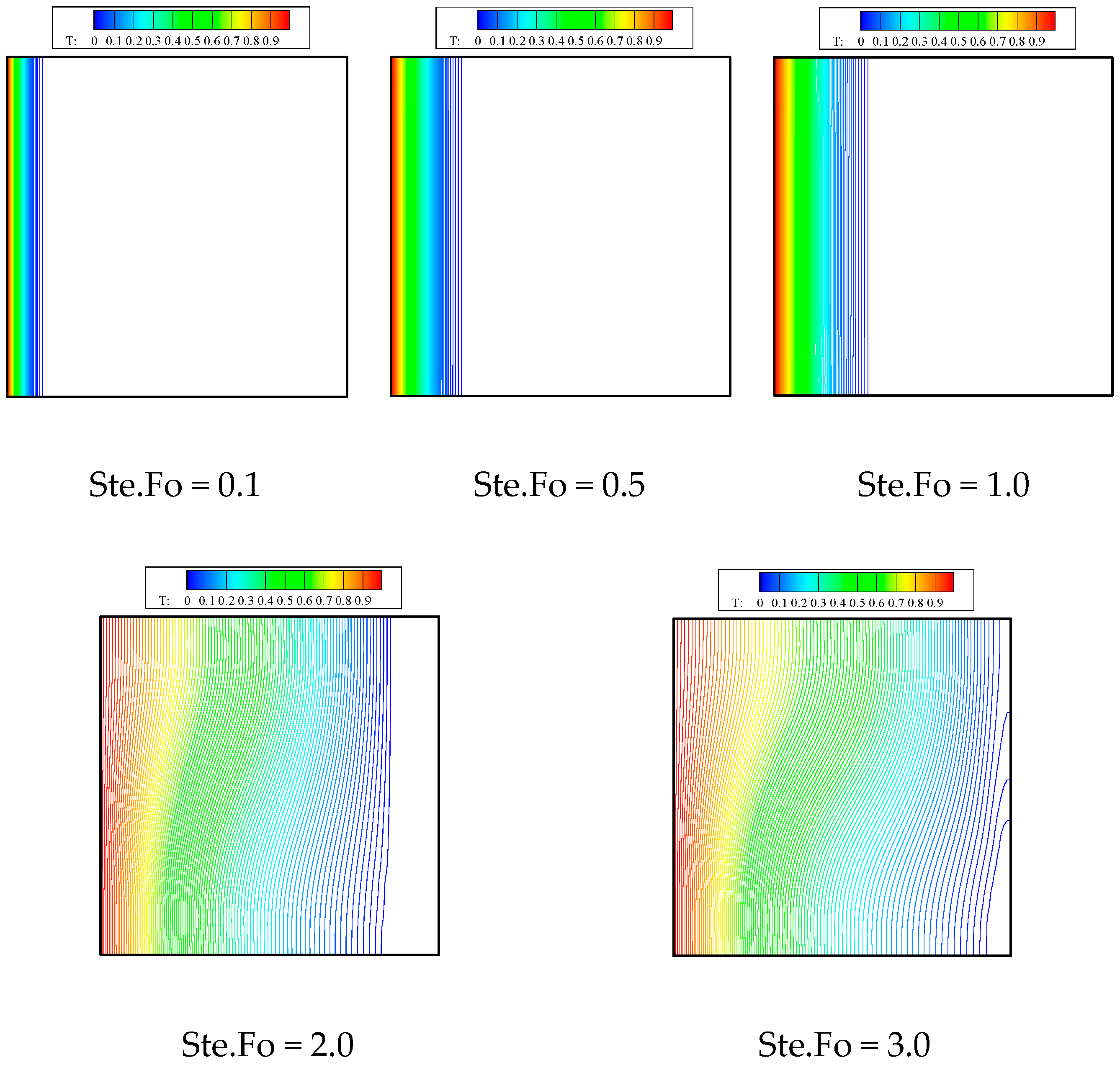
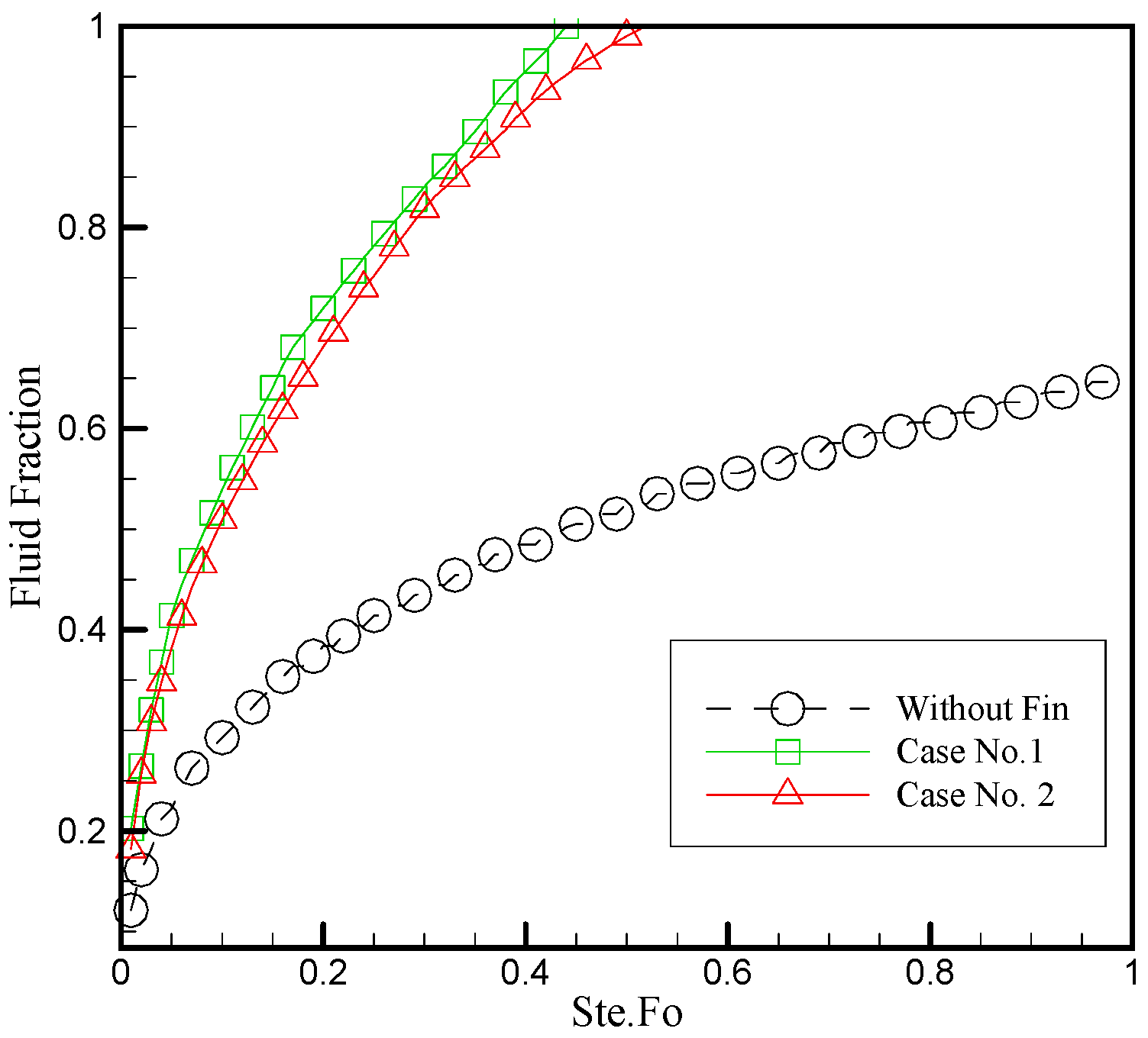
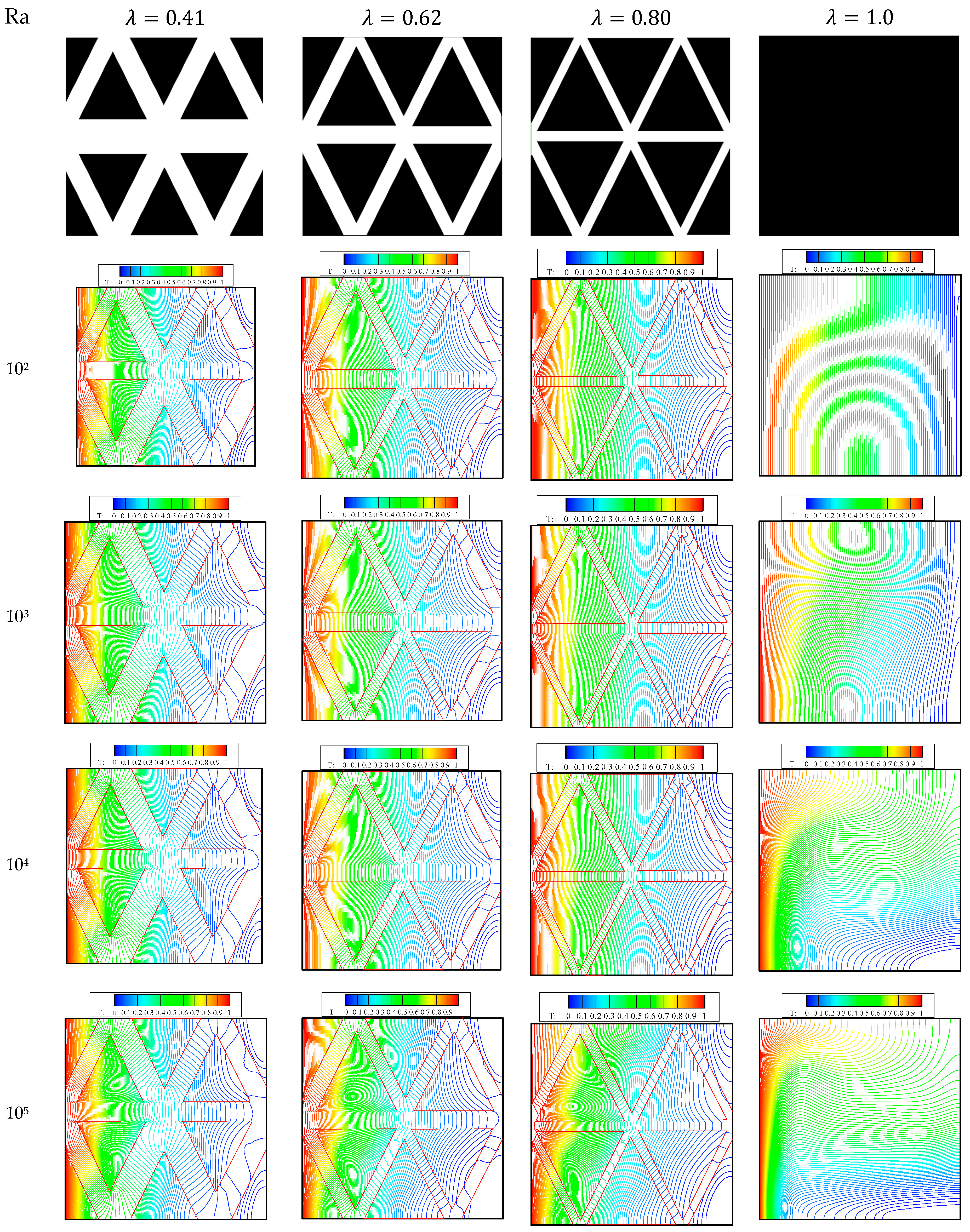
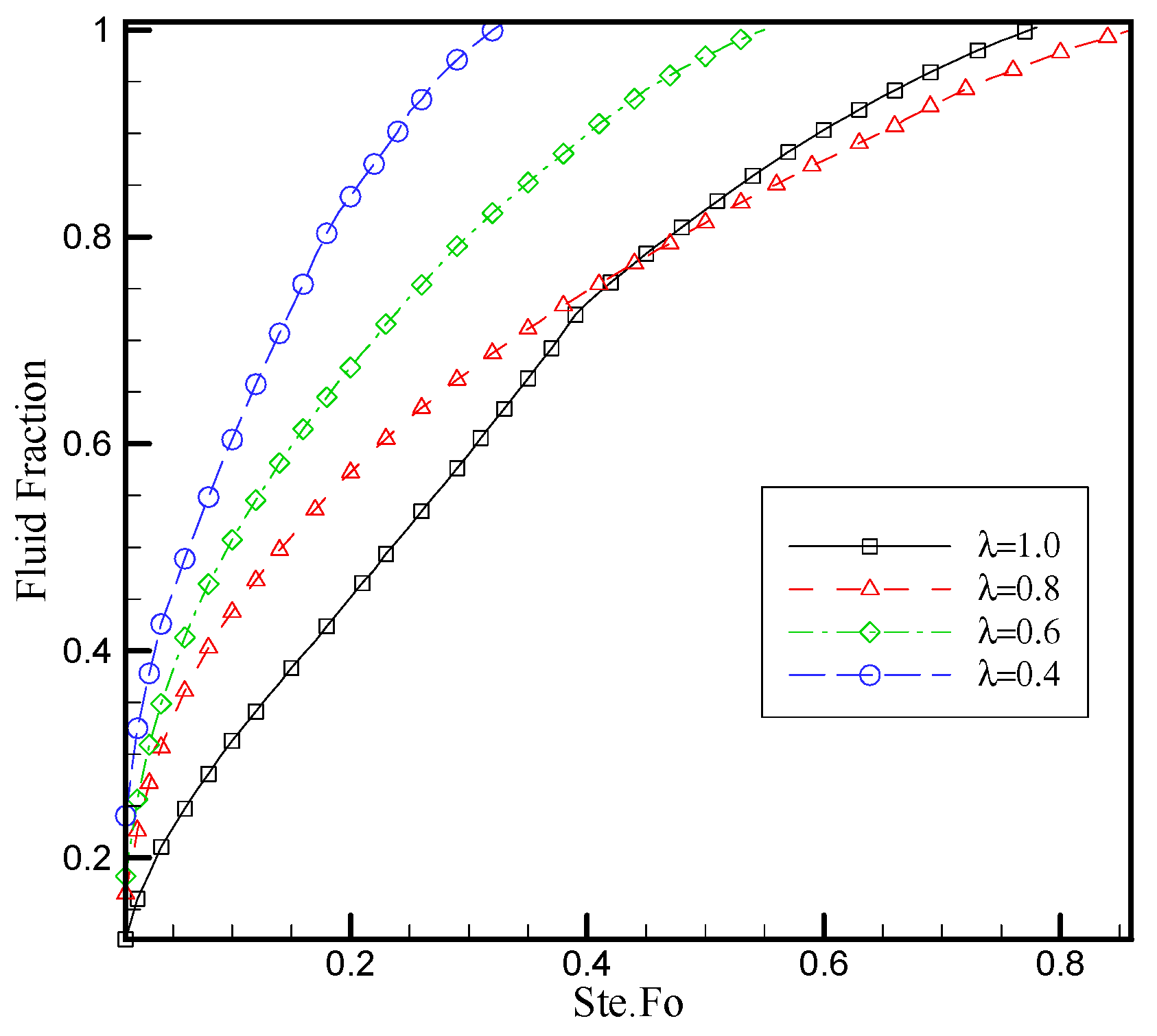
6.1. Effect of the Honeycomb Fin Structure

In this initial research endeavor, the influence of a honeycomb structure is investigated by contrasting its effects in two scenarios with varying Rayleigh (Ra) numbers within an equivalent domain size. The study employs visual aids including streamlines and fluid fraction diagrams. By comparing the results from cases with lower and higher Ra numbers, discernible patterns and differences in behavior emerge, shedding light on the structure’s impact under differing thermal conditions. This investigation sets the groundwork for deeper insights into the intricate dynamics and serves as a springboard for subsequent studies.
Figure 6, Figure 7 and Figure 8 illustrates isothermal lines within the cavity at a Ra value of 102, showcasing two distinct scenarios: one with the presence of a honeycomb structure and the other without when λ = 0.62 . Figure 6 illustrates that in the absence of fins, conductive heat transfer dominates over convective heat transfer because the slopes of the temperature profiles are very small, even though with the expansion of heat toward the center of the enclosure, the effect of gravity becomes such that the temperature profiles become slightly inclined. In honeycomb fin system 1, considering that the thermal conductivity coefficient of the fins is higher than that of the phase change materials (PCMs), heat reaches the center of the enclosure at a faster rate, causing each PCM compartment to melt at a faster pace because these compartments are exposed to heat from all sides and melt more quickly. In the case of system number 2, the design of the fin system plays a crucial role in the heat transfer dynamics. In this system, it is observed that heat initially reaches the central fins at a higher rate due to their specific arrangement within the enclosure. However, the process of phase change, particularly the melting process, exhibits a similar behavior to that observed in system number 1.
In a scenario where there is no fin system within the enclosure, the entire enclosure undergoes melting within a time interval known as Ste.Fo (which appears to be equal to 3.0). This time interval signifies the duration required for the material to transition from one state (e.g., solid) to another (e.g., liquid) at lower temperatures.
However, when a fin system is present within the enclosure, this time interval significantly decreases to 0.45. This reduction indicates that the presence of the fin system has a substantial impact on its thermal design and performance. It is likely that the fin system enhances heat transfer and accelerates the melting process of the material within the enclosure. This is a crucial advantage, particularly in applications that require precise temperature control and expedited phase change processes.
In summary, the inclusion or exclusion of a fin system within the enclosure significantly influences the duration of the phase change process. The presence of the fin system can significantly improve heat transfer and expedite the melting process within the enclosure. This effect can be particularly significant in applications where precise temperature control and the timing of processes are crucial.
What stands out from comparing the last point of melting within the enclosure for all three scenarios is that the design of the fin system can significantly influence the location and timing of the final point of melting.
Figure 9 visually demonstrates that the presence of fins accelerates the onset of the liquid phase, leading to a significantly faster melting process compared to the scenario without fins. Nevertheless, in both scenarios with fins, the complete melting of the PCM material occurs at roughly the same time. This observation underscores the role of fins in expediting the phase change process and ensuring more efficient heat transfer in the enclosure.
Figure 10, Figure 11 and Figure 12 display similar outcomes for Ra = 105. In both cases, with or without the fin system, a consistent result is observed. However, there is an interesting distinction when Ra = 105.
When the cavity lacks a fin system and Ra = 105, convection heat transfer takes precedence over heat conduction. This dominance of convection significantly accelerates the melt speed, resulting in a faster melting process compared to with lower Ra values. The increased Ra enhances the convective currents, leading to more efficient heat transfer and faster phase change within the enclosure.
In contrast, when the fin system is employed at Ra = 105, regardless of the specific configuration, the melting process mirrors that observed at Ra = 102. This suggests that the presence of fins mitigates the impact of the increased Ra, and in both cases, the melting process remains consistent with the conditions observed at Ra = 104.
In summary, Figure 10, Figure 11 and Figure 12 demonstrate that at higher Rayleigh numbers (Ra = 105), the absence of fins results in convection heat transfer dominating heat conduction, leading to an accelerated melting process. However, the introduction of a fin system at Ra = 105 maintains the same melting behavior observed at lower Ra values. This underscores the stabilizing and standardizing effect of the fin system on the melting process under varying Rayleigh number conditions. The stabilization effect noted in enclosures with fins can be attributed to the dominance of conductive heat transfer over convective heat transfer. Fins are designed to enhance heat dissipation by increasing the surface area available for heat exchange. In this specific context, the fins facilitate a more efficient conduction of heat from the melting process to the surrounding medium. Conductive heat transfer is inherently more predictable and controllable than convective heat transfer. The presence of fins promotes a higher conductive heat transfer rate, leading to a more stable and consistent fluid fraction behavior during the melting process. This behavior is particularly pronounced across different Rayleigh numbers (Ra), indicating the robustness of the observed stabilization effect. Figure 10, Figure 11 and Figure 12 showcase a noteworthy observation—the temperatures within the fins exhibit a rapid ascent. This phenomenon has a profound impact on the surrounding phase change material (PCM) containers. The accelerated temperature rise in the fins plays a pivotal role in creating a conducive environment for enhanced heat transfer to the PCM containers. Consequently, the PCM experiences a faster and more substantial melting process. Notably, a larger quantity of heat is transferred and stored within the PCM in a significantly shorter period. This transient effect suggests that the inclusion of fins in the configuration not only expedites the melting process but also augments the overall heat storage capacity of the PCM. The dynamic nature of temperature distribution, as depicted in Figure 10, Figure 11 and Figure 12, underscores the influence of fins on the temporal aspects of thermal behavior. These findings highlight the efficiency gains achieved by leveraging transient simulations and the strategic use of fins in optimizing heat transfer and storage in PCM systems.
Figure 13 presents a fluid fraction diagram for the case where Ra = 105. Comparing this to the results at lower Ra values, it is evident that the fluid diagrams for systems with fins exhibit a consistent pattern. However, a notable difference is observed in the fluid fraction diagram when fins are absent. This indicates that the presence or absence of fins plays a crucial role in dictating the fluid behavior at high Ra numbers.
Figure 14 and Figure 15 further illustrate the impact of the Rayleigh number (Ra) on the fluid fraction diagram. Clearly, as the Ra number increases, the melting time decreases. This relationship is consistent with the expectation that higher Ra numbers result in more vigorous convective currents, leading to faster heat transfer and phase change within the enclosure.
However, in cavities equipped with fins, the change in Ra number does not yield a significant difference in the observed results. This suggests that the presence of fins stabilizes and standardizes the melting process, making it less sensitive to variations in the Ra number. The fins appear to enhance the heat transfer and maintain a consistent melting behavior, even as the Ra number increases.
In summary, Figure 14 highlights that at Ra = 105, the fluid fraction diagram is different when fins are absent, while systems with fins exhibit consistent behavior. Figure 13, Figure 14 and Figure 15 affirm the inverse relationship between the Ra number and melting time, but this effect is less pronounced in cavities equipped with fins, indicating the stabilizing influence of fins on the melting process, regardless of Ra variations.
In a cavity without a fin system, the study conducted by Yan et al. revealed a significant correlation between the Rayleigh (Ra) number and the melting time of the material. The experiment demonstrated that as the Ra number increased from 102 to 105, there was a notable decrease in the melting time, plummeting from 6 to 0.4. This observation underscores the influential role of the Ra number in dictating the melting behavior within the cavity. Intriguingly, the introduction of a fin system proved to be a transformative factor, uniformly reducing the melting time to Ste.Fo = 0.5 across all cases. This finding underscores the effectiveness of a fin system in optimizing the thermal dynamics within the cavity, resulting in a substantial and consistent reduction in the melting time regardless of the Ra number. The utilization of fins appears to offer a promising and universal solution for enhancing heat transfer and expediting the melting process in such systems.
The impact of fins on fluid behavior and their role in mitigating gravitational effects during melting processes is integral to our study. Fins enhance heat transfer by increasing the surface area, facilitating efficient phase change, and inducing favorable convective flow patterns. Moreover, strategically designed fins counteract the influence of gravity, minimizing undesired stratification and promoting uniform melting within the enclosure. The combined effects of enhanced heat transfer and gravity mitigation highlight the intricate interplay between fins and the enclosure, contributing to a more comprehensive understanding of thermal management systems and their applications in controlled phase change processes.
The parameter λ is defined as the ratio between the phase change material (PCM) space and the entire domain. In this section, we delve into the influence of λ on the melting process.
The images in the top row of Figure 16 and Figure 17 illustrate the geometry definition within the enclosure. Using geometric calculations, various values of the dimensionless parameter λ can be defined. It is observed that in the study of case number 1, reducing the value of λ from 1 to 0.4 results in a more uniform temperature distribution within the enclosure. This change becomes more pronounced at higher Rayleigh numbers (Ra) because at higher Ra numbers, convective heat transfer dominates over conductive heat transfer, leading to more significant temperature variations within the enclosure.
At lower λ values, due to the enhanced heat transfer effects of the fins, the volume of fluid within the enclosure decreases. This, in turn, accentuates the impacts of conductive heat transfer.
Figure 18 and Figure 19 shows fluid fraction diagram versus Ste.FO at different λ number at Ra = 105. Reducing λ by increasing the fin thickness can cut the melting time by 50%, but this comes with drawbacks. The thicker fins lead to a heavier system and reduced energy storage due to a lower amount of phase change material (PCM). Decisions to decrease λ should balance the reduced melting time benefits against the increased weight and diminished energy storage concerns.

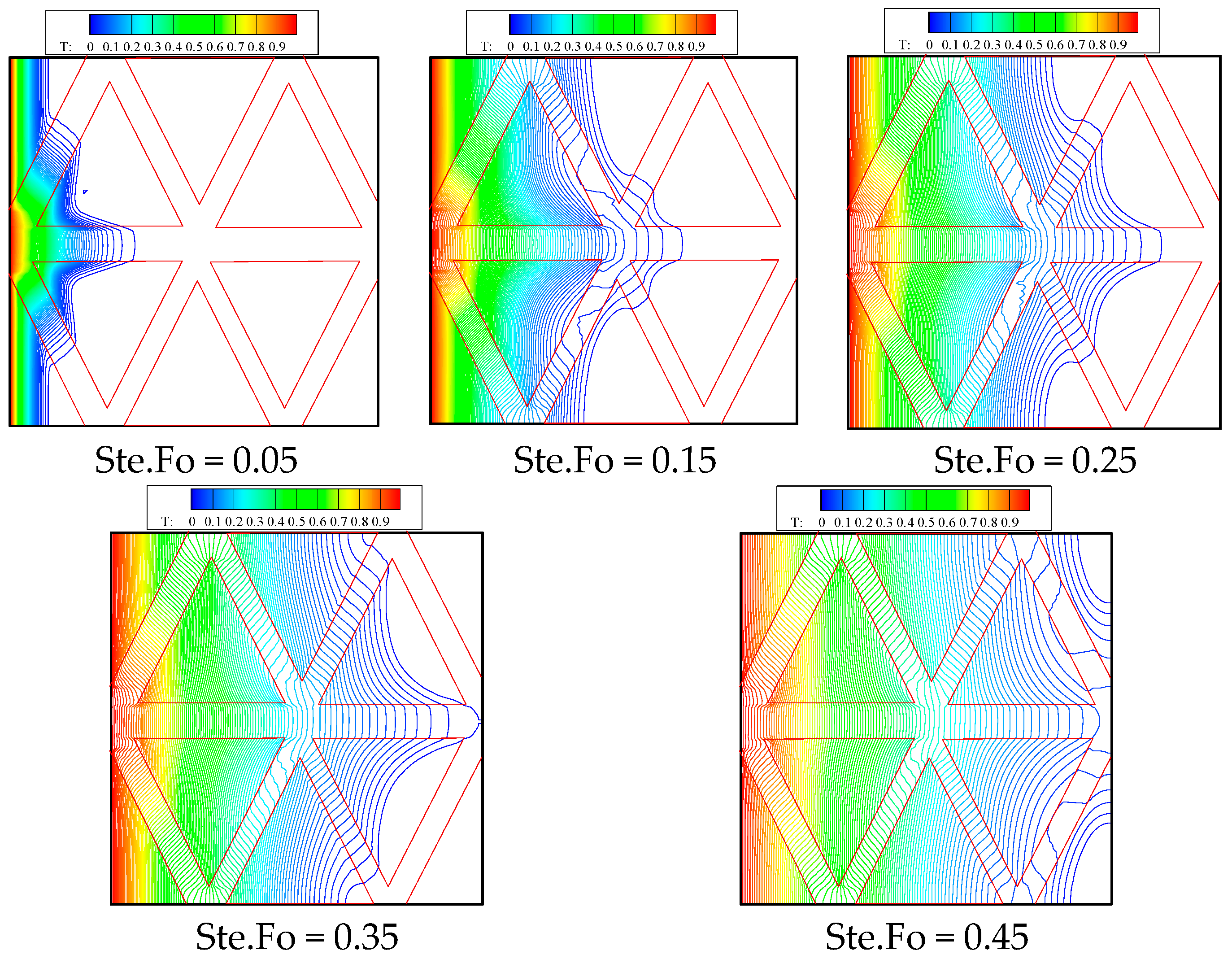
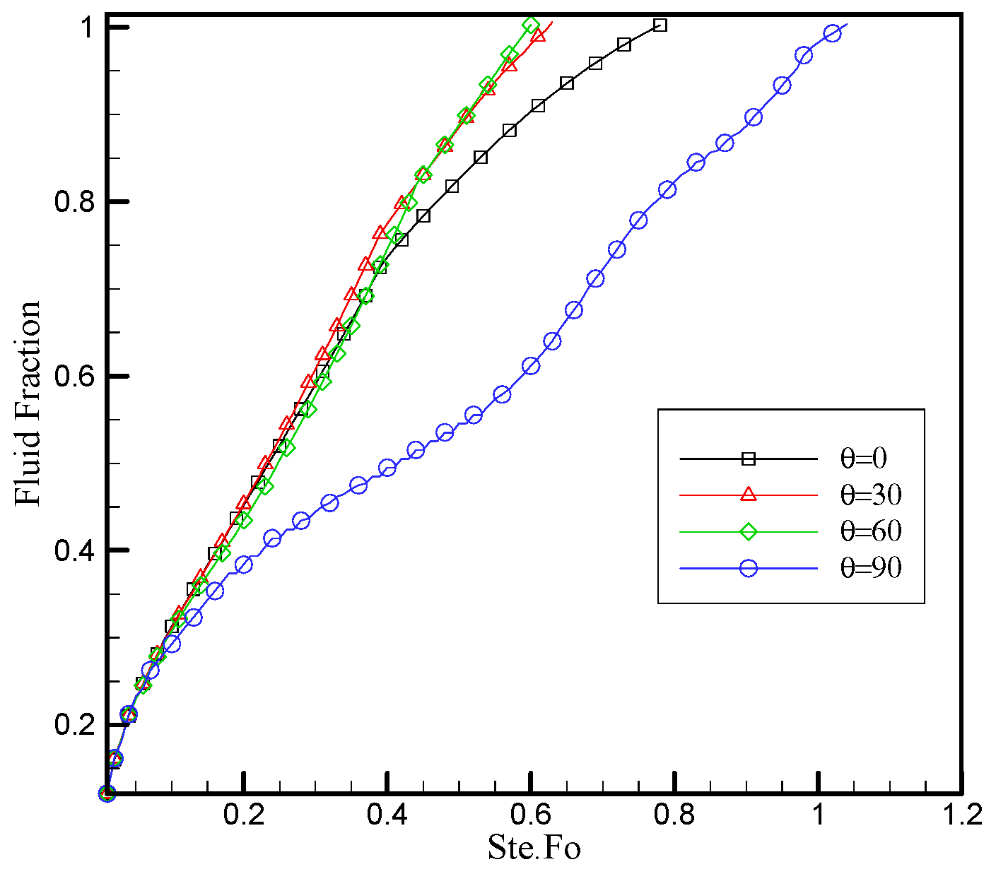
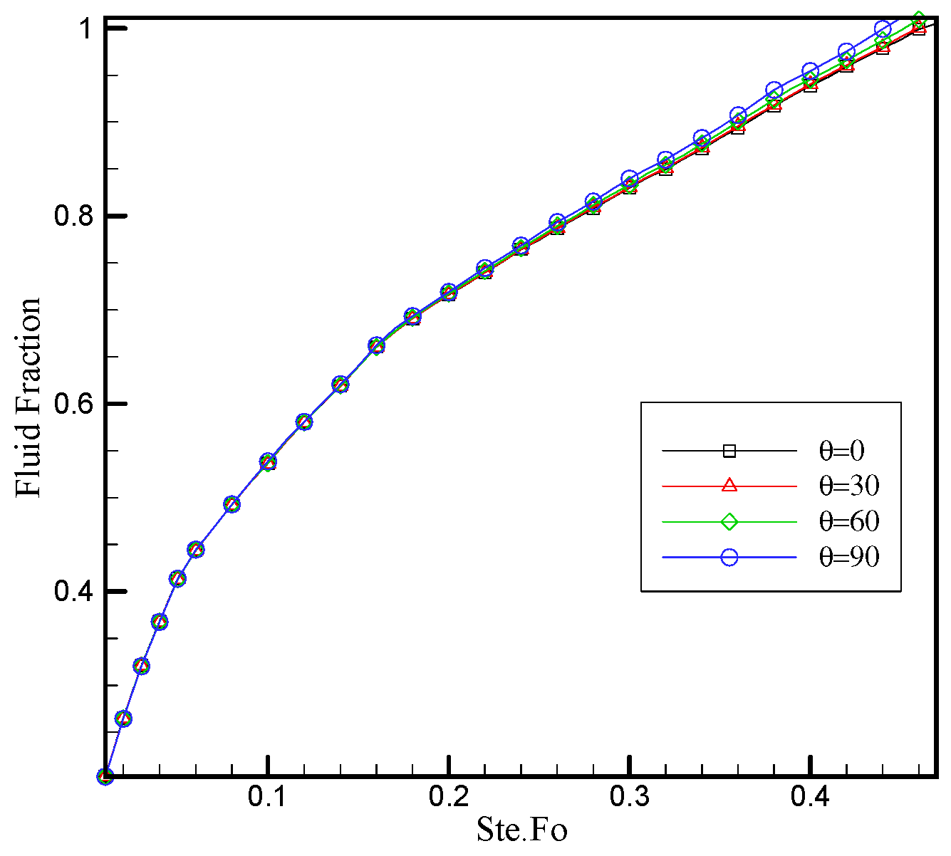
6.2. The Effect of Honeycomb Structure on Inclined Cavities

In the realm of heat transfer research, inclined cavities serve as essential tools for investigating heat exchange phenomena under non-standard gravitational conditions. These cavities, featuring various geometries, offer a unique platform for studying natural convection dynamics when buoyancy forces play a pivotal role, as seen in solar collectors and passive cooling systems. Additionally, they facilitate insightful analyses of the melt and solidification processes, influencing solidification fronts, heat transfer rates, and phase change behaviors. The insights gleaned from these studies significantly contribute to both theoretical advancements and practical applications in materials science and engineering.
Building upon the current research, this investigation aims to further examine the influence of the cavity angle on a honeycomb constructed finned cavity. The purpose of this investigation is to reach a deeper understanding of how the orientation of cavities affects the melting dynamics of phase change materials (PCMs). Thus, the fluid fraction diagram at Ra = 105 at different cavity angles θ = 90   ,   45 ,   0   ,   45 ,   90 is presented in Figure 20, Figure 21 and Figure 22. In all cases discussed, λ is considered to be 0.6. This parameter, representing the ratio between the phase change material (PCM) space and the entire domain, is held constant at 0.6 for the purposes of the analysis and comparisons made in the study.
Figure 20 illustrates that in the case where the enclosure lacks fins, the angle of the enclosure has a significant impact on the fluid fraction diagram. However, with the presence of fins within the enclosure (Figure 21 and Figure 22), it can be observed that the angle has a minimal effect in both cases. This phenomenon stems from the fact that the presence of the fin system within the enclosure minimizes the influence of gravitational forces within the enclosure. As a result, changes in the angle of the enclosure do not have a substantial impact on the melting process.

7. Conclusions

Our study drew inspiration from the efficiency of nature’s hexagonal honeycomb structure to enhance the performance of our proposed system. Via the use of image processing algorithms, we precisely defined hexagonal phase change material (PCM) containers and thermally conductive fins, replicating the intricate geometry seen in honeycombs. This approach not only streamlined the setup process but also contributed to a deeper understanding of the melting process within the cavity, showcasing the benefits of biomimetic design principles in engineering applications.
The introduction of a fin system within the enclosure is associated with a substantial reduction in the time required for a complete phase change, with Ste.Fo decreasing significantly to approximately 0.45, highlighting the profound impact of fin systems on the thermal design and performance of the enclosure.
Enhanced heat transfer dynamics and accelerated melting processes are enabled by fin systems, rendering them advantageous for applications prioritizing precise temperature control and expedited phase change. Moreover, the critical role of fin system design is emphasized, as both scenarios with fins exhibit a faster onset of the liquid phase, but the location and timing of the final point of melting can be significantly influenced by the fin system configuration. Thus, the choice of fin system design becomes pivotal, significantly affecting the location and timing of the final point of melting. These findings contribute to a broader understanding of thermal management systems and their potential applications in industries necessitating precise temperature control and rapid phase change processes.
Our study reveals that the presence of fins in enclosures at different Rayleigh numbers (Ra) leads to consistent fluid fraction behavior and stabilizes the melting process. Additionally, an inverse relationship between the Ra and melting time is observed, but this effect is attenuated in cavities equipped with fins. These findings underscore the critical role of fins in enhancing thermal stability during phase change process.
Our study reveals that the cavity angle significantly affects the fluid fraction diagram in cavities without fins but has minimal impact when fins are present. This underscores the stabilizing role of fins in mitigating gravitational effects during melting processes. These insights enhance our understanding of how cavity geometry and fins interact in heat transfer, offering potential for improved thermal system designs.
In conclusion, our study’s outcomes not only advance the understanding of thermal dynamics but also hold significant implications for future engineering applications. The integration of hexagonal phase change material (PCM) containers and thermally conductive fins, inspired by nature’s honeycomb structure, demonstrates a practical and efficient approach to biomimetic design. The streamlined setup process, facilitated by image processing algorithms, showcases the potential for precise temperature control and accelerated phase change in diverse industries. The observed reduction in the phase change time and the influential role of the fin design in shaping thermal outcomes underscore the transformative impact of our findings. Furthermore, the consistent fluid fraction behavior and stabilization of the melting process in enclosures with fins, irrespective of varying Rayleigh numbers, highlight the universal applicability of fin systems. This study not only contributes to our current understanding of thermal management systems but also lays the groundwork for future research, emphasizing the enduring importance of these results in shaping the future of thermal sciences and applications.

Author Contributions

Conceptualization, A.R., M.D. and M.A.; methodology, A.R. and M.A.; validation, A.R., M.D. and M.A.; formal analysis, A.R. and M.A.; investigation, M.A. and M.D.; resources, M.A.; writing—original draft preparation, A.R.; writing—review and editing, A.R., M.A. and M.D.; visualization, A.R., M.D. and M.A.; supervision, M.A. and M.D.; project administration, M.A. and M.D. All authors have read and agreed to the published version of the manuscript.

Funding

This research received no external funding.

Data Availability Statement

Data are available upon request.

Conflicts of Interest

The authors declare no conflict of interest.

Abbreviations

Nomenclature
c i   (m/s)the discrete velocity of Boltzmann grid
c p   ( m / s )specific heat at constant pressure
c s (m/s)sound speed
F   ( J ) buoyancy force
f the distribution function
h n , k fluid fraction at time step n and iteration k
f e q the local equilibrium distribution function
g y ( m / s 2 ) the gravitational acceleration
g temperature distribution function
g i e q the local equilibrium distribution function of temperature
G r Grashof number
k ( W / m 2 · K ) conduction heat transfer coefficient
L (m)the width of the cavity
L f ( J k g ) Latent heat
P r Prandtl number
R a Rayleigh number
T (K)temperature
t   (s)time
u   (m/s)velocity component in the x-direction
v   ( m / s ) velocity component in the y-direction
u 0 ( m / s ) the velocity of the top wall
w i the weight function of the ith direction
Greek
α   ( m 2 / s ) thermal diffusivity
μ   ( m 2 / s ) viscosity
ρ ( k g / m 3 )density
τ v the relaxation time of the flow field
τ D the relaxation time of the temperature field
ν kinematic viscosity
Footnotes
f fluid
w wall
Abbreviations
PCMphase change material
LBMlattice Boltzmann method

References

  1. Tripathi, B.M.; Shukla, S.K.; Rathore, P.K.S. A comprehensive review on solar to thermal energy conversion and storage using phase change materials. J. Energy Storage 2023, 72, 108280. [Google Scholar] [CrossRef]
  2. Cui, H.; Zou, Y.; Yang, H.; Bao, X. Thermal-mechanical behaviors of concrete with innovative salt hydrate PCM-based thermal energy storage aggregate. Energy Convers. Manag. 2023, 293, 117477. [Google Scholar] [CrossRef]
  3. Chavan, S.; Venkateswarlu, B.; Prabakaran, R.; Salman, M.; Joo, S.W.; Choi, G.S.; Kim, S.C. Thermal runaway and mitigation strategies for electric vehicle lithium-ion batteries using battery cooling approach: A review of the current status and challenges. J. Energy Storage 2023, 72, 108569. [Google Scholar] [CrossRef]
  4. Mubarrat, M.; Mashfy, M.M.; Farhan, T.; Ehsan, M.M. Research Advancement and Potential Prospects of Thermal Energy Storage in Concentrated Solar Power Application. Int. J. Thermofluids 2023, 20, 100431. [Google Scholar] [CrossRef]
  5. Liu, Z.; Du, J.; Steere, R.; Schlegel, J.P.; Khayat, K.H.; Meng, W. Cement-Based Materials with Solid–Gel Phase Change Materials for Improving Energy Efficiency of Building Envelope. J. Mater. Civ. Eng. 2023, 35, 04023425. [Google Scholar] [CrossRef]
  6. Yang, T.; Ding, Y.; Li, B.; Athienitis, A.K. A review of climate adaptation of phase change material incorporated in building envelopes for passive energy conservation. Build. Environ. 2023, 244, 110711. [Google Scholar] [CrossRef]
  7. Nguyen, V.N.; Le, T.L.; Duong, X.Q.; Le, V.V.; Nguyen, D.T.; Nguyen, P.Q.P.; Rajamohan, S.; Vo, A.V.; Le, H.S. Application of phase change materials in improving the performance of refrigeration systems. Sustain. Energy Technol. Assess. 2023, 56, 103097. [Google Scholar] [CrossRef]
  8. Hu, C.; Sha, L.; Huang, C.; Luo, W.; Li, B.; Huang, H.; Xu, C.; Zhang, K. Phase change materials in food: Phase change temperature, environmental friendliness, and systematization. Trends Food Sci. Technol. 2023, 140, 104167. [Google Scholar] [CrossRef]
  9. Dardouri, S.; Mankai, S.; Almoneef, M.M.; Mbarek, M.; Sghaier, J. Energy performance based optimization of building envelope containing PCM combined with insulation considering various configurations. Energy Rep. 2023, 10, 895–909. [Google Scholar] [CrossRef]
  10. Nikolaidis, P. Solar Energy Harnessing Technologies towards De-Carbonization: A Systematic Review of Processes and Systems. Energies 2023, 16, 6153. [Google Scholar] [CrossRef]
  11. Odoi-Yorke, F.; Opoku, R.; Davis, F.; Obeng, G.Y. Optimisation of thermal energy storage systems incorporated with phase change materials for sustainable energy supply: A systematic review. Energy Rep. 2023, 10, 2496–2512. [Google Scholar] [CrossRef]
  12. Soodmand, A.M.; Azimi, B.; Nejatbakhsh, S.; Pourpasha, H.; Farshchi, M.E.; Aghdasinia, H.; Mohammadpourfard, M.; Heris, S.Z. A comprehensive review of computational fluid dynamics simulation studies in phase change materials: Applications, materials, and geometries. J. Therm. Anal. Calorim. 2023, 148, 10595–10644. [Google Scholar] [CrossRef]
  13. Quan, L.; Pan, Z. Investigating the thermal behavior of phase change materials of ethylene glycol-filled SiO2 plates in the presence of solar radiation by molecular dynamics simulation. Eng. Anal. Bound. Elem. 2023, 150, 1–6. [Google Scholar] [CrossRef]
  14. Yan, G.; Alizadeh, A.; Rahmani, A.; Zarringhalam, M.; Shamsborhan, M.; Nasajpour-Esfahani, N.; Akrami, M. Natural convection of rectangular cavity enhanced by obstacle and fin to simulate phase change material melting process using Lattice Boltzmann method. Alex. Eng. J. 2023, 81, 319–336. [Google Scholar] [CrossRef]
  15. Triki, R.; Chtourou, S.; Baccar, M. Heat transfer enhancement of phase change materials PCMs using innovative fractal H-shaped fin configurations. J. Energy Storage 2023, 73, 109020. [Google Scholar] [CrossRef]
  16. Zhang, T.; Huo, D.; Wang, C.; Shi, Z. Review of the modeling approaches of phase change processes. Renew. Sustain. Energy Rev. 2023, 187, 113724. [Google Scholar] [CrossRef]
  17. Moreira, M.; Silva, T.; Dias-de-Oliveira, J.; Neto, F.; Amaral, C. Numerical modelling of radiant systems and phase change materials in building applications—A review. Appl. Therm. Eng. 2023, 234, 121342. [Google Scholar] [CrossRef]
  18. Pignata, A.; Minuto, F.D.; Lanzini, A.; Papurello, D. A feasibility study of a tube bundle exchanger with phase change materials: A case study. J. Build. Eng. 2023, 78, 107622. [Google Scholar] [CrossRef]
  19. Rashid, F.L.; Eisapour, M.; Ibrahem, R.K.; Talebizadehsardari, P.; Hosseinzadeh, K.; Abbas, M.H.; Mohammed, H.I.; Yvaz, A.; Chen, Z. Solidification enhancement of phase change materials using fins and nanoparticles in a triplex-tube thermal energy storage unit: Recent advances and development. Int. Commun. Heat Mass Transf. 2023, 147, 106922. [Google Scholar] [CrossRef]
  20. Wang, Y.; Ma, Y.; Chao, H. Machine learning and computational fluid dynamics based optimization of finned heat pipe radiator performance. J. Build. Eng. 2023, 78, 107612. [Google Scholar] [CrossRef]
  21. Li, S.J.; Zhu, L.T.; Zhang, X.B.; Luo, Z.H. Recent Advances in CFD Simulations of Multiphase Flow Processes with Phase Change. Ind. Eng. Chem. Res. 2023, 62, 10729–10786. [Google Scholar] [CrossRef]
  22. Rocha, T.T.M.; Teggar, M.; Trevizoli, P.V.; de Oliveira, R.N. Potential of latent thermal energy storage for performance improvement in small-scale refrigeration units: A review. Renew. Sustain. Energy Rev. 2023, 187, 113746. [Google Scholar] [CrossRef]
  23. Hu, Y.; Jasim, D.J.; Alizadeh, A.A.; Rahmani, A.; Al-Shati, A.S.; Zarringhalam, M.; Shamsborhan, M.; Nasajpour-Esfahani, N. Simulation of heat transfer in a nanoparticle enhanced phase change material to design battery thermal management systems: A lattice Boltzmann method study. J. Taiwan Inst. Chem. Eng. 2023, 152, 105137. [Google Scholar] [CrossRef]
  24. Nasehi, P.; Jamekhorshid, A. Simulation and optimization of a modified geometry LHTES system using needle-shaped fins. Multiscale Multidiscip. Model. Exp. Des. 2023, 1–14. [Google Scholar] [CrossRef]
  25. Nedumaran, M.S.; Gnanasekaran, N.; Hooman, K. Extensive analysis of PCM-based heat sink with different fin arrangements under varying load conditions and variable aspect ratio. J. Energy Storage 2023, 73, 108870. [Google Scholar] [CrossRef]
  26. Palacios, A.; Navarro-Rivero, M.E.; Zou, B.; Jiang, Z.; Harrison, M.T.; Ding, Y. A perspective on Phase Change Material encapsulation: Guidance for encapsulation design methodology from low to high-temperature thermal energy storage applications. J. Energy Storage 2023, 72, 108597. [Google Scholar] [CrossRef]
  27. Sarath, K.P.; Osman, M.F.; Mukhesh, R.; Manu, K.V.; Deepu, M. A review of the recent advances in the heat transfer physics in latent heat storage systems. Therm. Sci. Eng. Prog. 2023, 42, 101886. [Google Scholar] [CrossRef]
  28. Kumar, S.; Panda, D.; Ghodke, P.; Gangawane, K.M. Lattice Boltzmann method for heat transfer in phase change materials: A review. J. Therm. Anal. Calorim. 2023, 148, 9263–9287. [Google Scholar] [CrossRef]
  29. Ahn, J.; Song, J.C.; Lee, J.S. An Immersed Boundary Method for Conjugate Heat Transfer Involving Melting/Solidification. Int. J. Aeronaut. Space Sci. 2023, 24, 1–10. [Google Scholar] [CrossRef]
  30. Huber, C.; Parmigiani, A.; Chopard, B.; Manga, M.; Bachmann, O. Lattice Boltzmann model for melting with natural convection. Int. J. Heat. Fluid. Flow. 2008, 29, 1469–1480. [Google Scholar] [CrossRef]
  31. Wang, M.; Cheng, X.; Huo, Y.; Rao, Z. The lattice Boltzmann model for the heat and mass transfer of latent functional thermal fluid using enthalpy-transforming method. J. Energy Storage 2023, 64, 107189. [Google Scholar] [CrossRef]
  32. Peng, W.; Sadaghiani, O.K. Thermal function improvement of phase-change material (PCM) using alumina nanoparticles in a circular-rectangular cavity using Lattice Boltzmann method. J. Energy Storage 2021, 37, 102493. [Google Scholar] [CrossRef]
  33. Li, D.; Yu, Z. Natural convection melting in a cubic cavity with internal fins: A lattice Boltzmann study. Case Stud. Therm. Eng. 2021, 25, 100919. [Google Scholar] [CrossRef]
  34. Ghalambaz, M.; Sheremet, M.; Raizah, Z.; Akkurt, N.; Ghalambaz, M. Latent heat thermal energy storage in a shell-tube design: Impact of metal foam inserts in the heat transfer fluid side. J. Energy Storage 2023, 73, 108893. [Google Scholar] [CrossRef]
  35. Reddy, B.D.; Rahul, S.V.S.; Harish, R. Impact of fin number and nanoparticle size on molten salt NanoPCM melting in finned annular space. J. Energy Storage 2023, 72, 108705. [Google Scholar] [CrossRef]
  36. Subasi, A.; Subasi, S.; Bayram, M.; Sarı, A.; Hekimoğlu, G.; Ustaoglu, A.; Gencel, O.; Ozbakkaloglu, T. Effect of carbon nanotube and microencapsulated phase change material utilization on the thermal energy storage performance in UV cured (photoinitiated) unsaturated polyester composites. J. Energy Storage 2023, 61, 106780. [Google Scholar] [CrossRef]
  37. Zhao, C.; Opolot, M.; Liu, M.; Bruno, F.; Mancin, S.; Hooman, K. Numerical study of melting performance enhancement for PCM in an annular enclosure with internal-external fins and metal foams. Int. J. Heat. Mass. Transf. 2020, 150, 119348. [Google Scholar] [CrossRef]
  38. Lashgari, S.; Mahdavian, A.R.; Arabi, H.; Ambrogi, V.; Marturano, V. Preparation of acrylic PCM microcapsules with dual responsivity to temperature and magnetic field changes. Eur. Polym. J. 2018, 101, 18–28. [Google Scholar] [CrossRef]
  39. Darzi, A.A.R.; Jourabian, M.; Farhadi, M. Melting and solidification of PCM enhanced by radial conductive fins and nanoparticles in cylindrical annulus. Energy Convers. Manag. 2016, 118, 253–263. [Google Scholar] [CrossRef]
  40. Ren, Q.; Chan, C.L. GPU accelerated numerical study of PCM melting process in an enclosure with internal fins using lattice Boltzmann method. Int. J. Heat. Mass. Transf. 2016, 100, 522–535. [Google Scholar] [CrossRef]
  41. Ren, Q.; Guo, P.; Zhu, J. Thermal management of electronic devices using pin-fin based cascade microencapsulated PCM/expanded graphite composite. Int. J. Heat. Mass. Transf. 2020, 149, 119199. [Google Scholar] [CrossRef]
  42. Zhang, J.; Cheng, Z.; Zhou, Y.; Lu, B.; Zhang, Y. Numerical study using lattice Boltzmann method on melting and solidification of NEPCM placed inside a rectangular cavity with a new double-fin arrangement. Appl. Therm. Eng. 2023, 219, 119619. [Google Scholar] [CrossRef]
  43. Alizadeh, M.; Shahavi, M.H.; Ganji, D.D. Performance enhancement of nano PCM solidification in a hexagonal storage unit with innovative fin shapes dealing with time-dependent boundary conditions. Energy Rep. 2022, 8, 8200–8214. [Google Scholar] [CrossRef]
  44. Sultan, M.; Mostafa, H.; El Boz, A.M.; Elngiry, E. Effect of Inlet and Geometrical Parameters on the Melting of PCM Capsules of Elliptical Cross Section. ERJ. Eng. Res. J. 2021, 44, 11–20. [Google Scholar] [CrossRef]
  45. Jourabian, M.; Farhadi, M.; Darzi, A.A.R. Simulation of natural convection melting in an inclined cavity using lattice Boltzmann method. Sci. Iran. 2012, 19, 1066–1073. [Google Scholar] [CrossRef]
  46. Rahmani, A.; Dibaj, M.; Akrami, M.; Akrami, M. Computational investigation of magnetohydrodynamic flow and melting process of phase change material in a battery pack using the lattice Boltzmann method. J. Energy Storage 2024, 78, 110046. [Google Scholar] [CrossRef]
Figure 1. Visual representation of the utilized geometry in this study: (a) case 1 and (b) case 2.
Energies 17 00351 g001aEnergies 17 00351 g001b
Figure 3. Grid study on different lattice sizes (50 × 50, 100 × 100, 150 × 150, 200 × 200, and 250 × 250).
Energies 17 00351 g003
Figure 4. Used grid in simulation of case 1.
Energies 17 00351 g004
Figure 5. Results for a cavity equipped by metal fin as used by Jourabian et al. ((a) Ste.Fo = 0.2, (b) Ste.Fo = 0.5, (c) Ste.Fo = 0.8) at Ra = 1.7 × 10⁴ and Ste = 10.0 at three time steps.
Energies 17 00351 g005
Figure 6. Isothermal line of cavity at Ra = 102 for a case without honeycomb structure.
Energies 17 00351 g006
Figure 7. Isothermal line of cavity at Ra = 102 for honeycomb structure case 1 and λ = 0.62 .
Energies 17 00351 g007
Figure 8. Isothermal line of cavity at Ra = 102 for honeycomb structure case 2 and λ = 0.62 .
Energies 17 00351 g008
Figure 9. Fluid fraction diagram of cavity at Ra = 102 for honeycomb structures and cavity without fin structures.
Energies 17 00351 g009
Figure 10. Fluid fraction diagram of cavity at Ra = 102 for cavity without fin structures.
Energies 17 00351 g010
Figure 11. Isothermal line of cavity at Ra = 105 for a case without honeycomb structure.
Energies 17 00351 g011
Figure 12. Isothermal line of cavity at Ra = 105 for a case with honeycomb structure case 1.
Energies 17 00351 g012
Figure 13. Fluid fraction diagram of cavity at Ra = 105 for honeycomb structures and cavity without fin structures.
Energies 17 00351 g013
Figure 14. Fluid fraction diagram of cavity at different Ra numbers for the case without fin structure.
Energies 17 00351 g014
Figure 15. Fluid fraction diagram of cavity at different Ra numbers for honeycomb structures: (a) case 1 and (b) case 2.
Energies 17 00351 g015aEnergies 17 00351 g015b
Figure 16. Impact of λ on PCM melting dynamics in honeycomb finned cavity (case 1) at different Ra numbers.
Energies 17 00351 g016
Figure 17. Impact of λ on PCM melting dynamics in honeycomb finned cavity (case 2) at different Ra numbers.
Energies 17 00351 g017
Figure 18. Fluid fraction diagram of cavity at different λ numbers for honeycomb structure case 1 at Ra = 105.
Energies 17 00351 g018
Figure 19. Fluid fraction diagram of cavity at different λ numbers for honeycomb structure case 2 at Ra = 105.
Energies 17 00351 g019
Figure 20. Impact of cavity angle on PCM melting dynamics at Ra = 105 in a cavity without fin.
Energies 17 00351 g020
Figure 21. Impact of cavity angle on PCM melting dynamics in honeycomb finned cavity (case 1) at Ra = 105.
Energies 17 00351 g021
Figure 22. Impact of cavity angle on PCM melting dynamics in honeycomb finned cavity (case 2) at Ra = 105.
Energies 17 00351 g022
Table 1. Thermophysical properties of phase change material (PCM).
PropertiesUnitParaffin-Wax
c p ( J / k g · K ) 2000
ρ ( k g / m 3 ) 800
k ( W / m K ) 0.2
L f ( J / k g ) 275
α = k ρ c p ( m 2 / s ) 1.25 × 10 7
Disclaimer/Publisher’s Note: The statements, opinions and data contained in all publications are solely those of the individual author(s) and contributor(s) and not of MDPI and/or the editor(s). MDPI and/or the editor(s) disclaim responsibility for any injury to people or property resulting from any ideas, methods, instructions or products referred to in the content.

