Article

Numerical Investigations of the Thermal-Hydraulic Characteristics of Microchannel Heat Sinks Inspired by Leaf Veins

Key Laboratory of Aircraft Environment Control and Life Support, MIIT, Nanjing University of Aeronautics and Astronautics, 29 Yudao St., Nanjing 210016, China
*
Author to whom correspondence should be addressed.
Energies 2024, 17(2), 311; https://doi.org/10.3390/en17020311
Submission received: 27 November 2023 / Revised: 26 December 2023 / Accepted: 4 January 2024 / Published: 8 January 2024
(This article belongs to the Section J1: Heat and Mass Transfer)

Abstract

:
A microchannel heat sink (MCHS) is a potential solution for chip and battery thermal management. The new microchannel structure is beneficial for further improving the thermal-hydraulic performance of MCHSs. Inspired by leaf veins, six new channel structures were designed, and the effects of the channel structures (three parallel structures named PAR I, II, and III and three pinnate structures named PIN I, II, and III), channel depths (0.4, 0.8, and 1.6 mm), and heat fluxes (20, 50, and 80 kW/m2) were investigated via numerical simulation. The cooling medium was water, and the heating area was 40 × 40 mm2. Both PAR II and PIN III exhibit superior overall performance, characterized by the highest Nusselt number and the lowest heating wall temperature. Moreover, PIN III demonstrates the lowest standard deviation in heating wall temperature, while PAR II exhibits the lowest friction factor. The greater the channel depth is, the larger the solid–liquid contact area is, leading to a reduced wall temperature at the interface under identical conditions of inlet Reynolds number and heating wall heat flux. Consequently, an increase in the Nusselt number corresponds to an increase in the friction factor. The maximum value and standard deviation of the heating wall temperature increase with increasing heat flux, while the Nusselt number and friction factor remain unaffected. The overheating near the two right angles of the outlet should be carefully considered for an MCHS with a single inlet–outlet configuration.

1. Introduction

With the rapid advancement of microelectronics and the increasing popularity of electric vehicles, the demand for efficient heat management in chips and batteries has become more critical than ever before [1,2,3,4]. Inadequate dissipation of heat can not only lead to equipment malfunction but also pose serious safety risks such as fires. Therefore, finding effective solutions to enhance heat transfer performance is a pressing challenge. One potential solution lies in the utilization of microchannel heat sinks (MCHSs). These innovative structures allow for the placement of a larger number of channels within limited spatial constraints, thereby significantly increasing the overall heat transfer area. By maximizing the surface contact between the cooling medium and hot components, MCHSs offer improved thermal efficiency compared to traditional cooling methods. However, conventional microchannel structures have limitations. One major drawback is high flow resistance, which hinders efficient fluid circulation through narrow channels. This can result in an increased pressure drop and reduced overall cooling effectiveness. Additionally, inadequate temperature uniformity across different regions within microchannels further compromises their performance. Consequently, the development of more innovative microchannel structures is necessary to address these shortcomings.
During the extensive process of natural evolution, numerous efficient fluid transport structures, such as tree crowns, leaf veins, and animal respiratory systems, have emerged [5,6,7,8]. These structures have been finely tuned by nature over millions of years to optimize fluid flow and maximize efficiency. The application of these structures to the design of microchannels is anticipated to address the aforementioned issues and further enhance the overall performance of MCHSs. A summary of the pertinent studies is presented below.
Inspired by the venation patterns of leaves, Asadi and Pourfattah [9] developed novel MCHSs for power electronic systems, which achieved superior cooling performance at an assumed heat flux of 100 W/cm2, including temperature reduction and uniformity, in comparison to conventional MCHSs with linear channels. Peng et al. [10] designed MCHSs featuring symmetrical and asymmetric secondary microchannels for electronic equipment and observed a more significant impact of the branching angle on the performance of asymmetric MCHSs due to enhanced vortex generation. Subsequently, they constructed MCHSs with tertiary microchannels based on the actual venation patterns of Osmanthus leaves and Voronoi diagrams and found that the addition of tertiary microchannels enhanced MCHS performance, with a higher channel density corresponding to an improved performance. For proton exchange membrane fuel cells (PEMFCs), Xia et al. [11] developed a leaf-like flow field structure and observed that compared to the conventional serpentine configuration, the novel design exhibited a reduced pressure drop, more uniform reaction gas distribution, and increased power output (up to an 8.5% improvement). Regarding the thermal management of lithium-ion batteries (LIBs), Alnaqi [12] and Deng et al. [13] explored leaf-like channels. Alnaqi [12] achieved heat transfer enhancement (up to 14%) by incorporating nanoparticles and elevating the inlet velocity via a 255 × 168 mm2 heat sink with an inlet velocity ranging from 0.01 to 0.05 m/s and corresponding Reynolds numbers between 200 and 1000. Deng [13] derived the optimal maximum temperature and temperature uniformity of LIBs, along with relevant structural parameters such as the width ratio, length ratio, and branching angle of the channels. They highlighted that the heat dissipation and power consumption requirements of LIBs could be met by appropriately designing the channel thickness and inlet velocity. The optimized range was determined with a width ratio of approximately 3/4, a length ratio of approximately 1/2, and a bifurcation angle ranging from 30° to 50°.
Inspired by other natural structures, Chen et al. [14], Wang et al. [15], Tan et al. [16], Yenigun and Cetkin [17], Han et al. [18], and Tan et al. [19] have recently designed innovative MCHSs for high heat flux chip cooling. Chen et al. [14] revealed that tree-shaped MCHSs exhibit significant advantages in terms of both heat transfer and pressure drop compared to those with traditional serpentine flow patterns. The tree-shaped structures demonstrated the inherent advantage of maintaining a uniform temperature on the heating wall. Moreover, the local pressure loss resulting from confluence flow was greater than that caused by diffluence flow. Wang et al. [15] compared the flow and heat transfer characteristics of symmetric/asymmetric tree-like branching networks and symmetric/asymmetric (offset) leaf-like branching networks. The impact of asymmetry was negligible for tree-like branching networks with a low number of branches. However, in leaf-like branching networks, offsetting could significantly reduce the pressure drop while maintaining the maximum temperature difference between the inlet and outlet of the flowing fluid. Tan et al. [16] developed four MCHSs, including ternate veiny, lateral veiny, snowflake-shaped, and spider-netted microchannels. The simulation results demonstrated that the spider-netted microchannel exhibited optimal performance. Experimental data corroborated the superior heat transfer capabilities of the spider-netted microchannel compared to those of the straight microchannel. The temperature difference between the heat sources cooled by these two channels reached up to 9.9 °C at a heat flux of 100 W/cm2. This was attributed to the enhanced convective fluid mixing in the spider-netted microchannel, which in turn improved the heat transfer efficiency. Furthermore, two design principles were proposed: maximizing the overall flow distribution within the channels and minimizing any difference in the flow rate. Yenigun and Cetkin [17] examined the characteristics of parallel, tree-shaped, and hybrid channels. They found that the flow resistance of tree-shaped channels was less than that of parallel channels. When the flow resistance was minimal, the peak temperature in the tree-shaped channels was lower; however, as the flow resistance increased, the parallel channels demonstrated superior cooling performance. Hybrid channels exhibited the lowest peak temperature and highest volume flow rate across the entire area. Han et al. [18] developed spider-netted MCHSs and employed topology optimization techniques to enhance the thermal efficiency. Their topological MCHSs, which were designed to minimize temperature differences and pressure drops, exhibited the best overall heat dissipation capacity, with a temperature difference reduction of 57.4% compared to spider-netted MCHSs for a Reynolds number of 2056.8. Tan et al. [19] analyzed the temperature distribution in two-phase spider-netted MCHSs with nonuniform heat flux and optimized a structure capable of achieving temperature uniformity within 2 °C for 150 W/cm2. In addition, Wang et al. [5] proposed a cold plate with spider-netted channels for thermal management of LIBs. Among the structural parameters of the spider-netted channel, the cooling performance of the cold plate was most significantly influenced by channel width, while channel angle had a minimal effect. However, increasing the channel width beyond 3 mm did not lead to further improvement in cooling performance. The optimal thermal balance for LIBs was achieved at a channel angle of 120°.
From the above summary, it is evident that there is a dearth of research concerning the performance of MCHSs inspired by bioinspired structures, with the primary focus being on leaf veins and spider webs. However, the natural diversity of leaf-vein structures far surpasses that reported in the current literature, offering a wealth of possibilities for the optimization of MCHSs. In this study, six types of MCHSs based on leaf-vein structures were designed and analyzed to investigate their cooling performance and optimize their channel configurations. Furthermore, the influence of channel depth and heat flux on heat sink characteristics was examined.

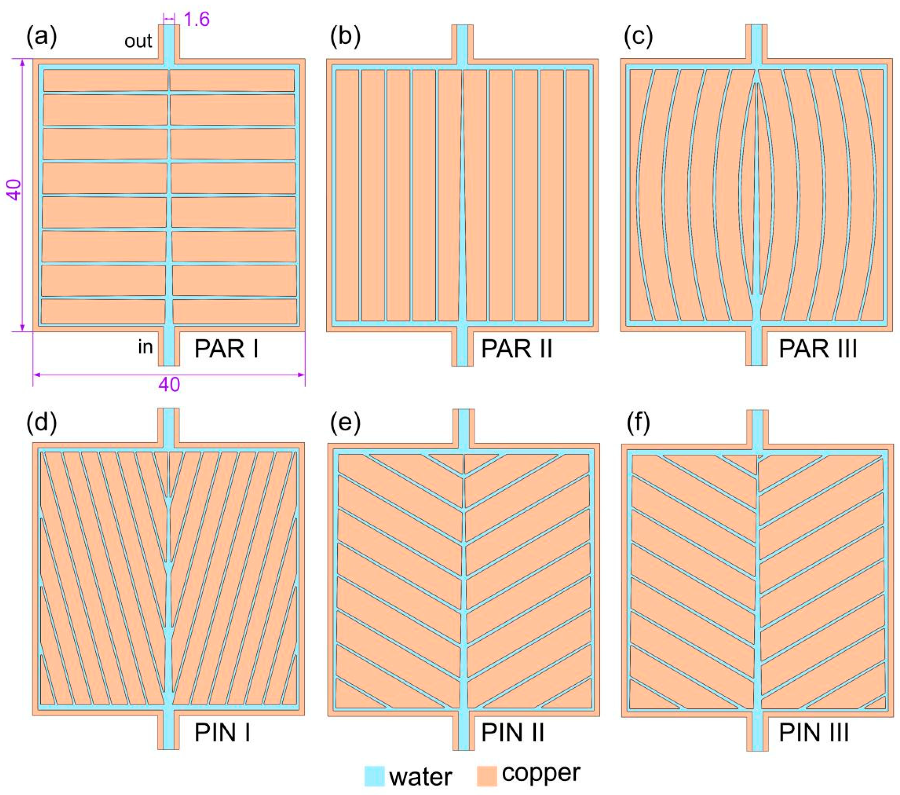
2. Design of Bioinspired MCHSs

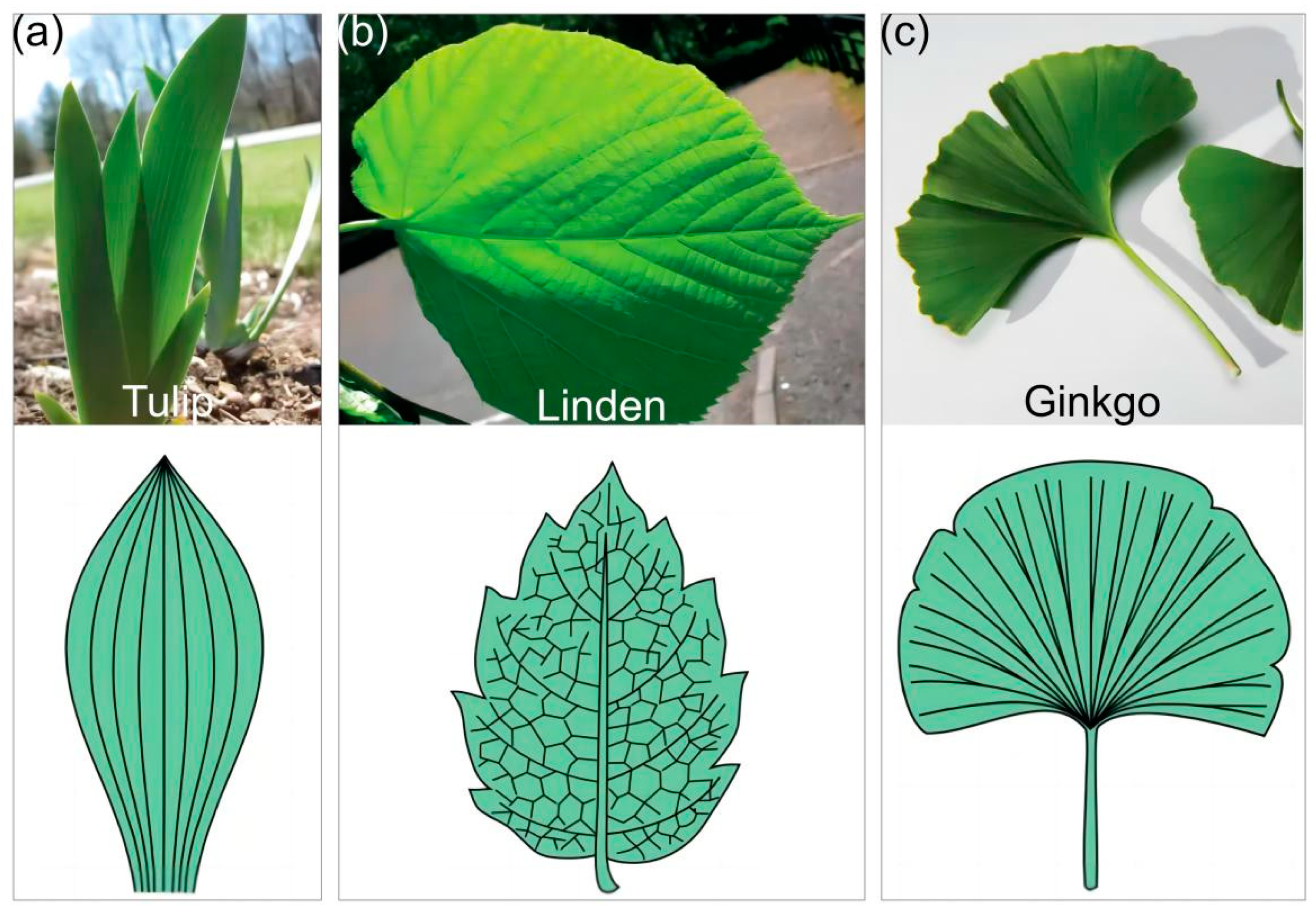
2.1. Natural Prototype

The pattern of veins within a leaf blade is referred to as venation. These veins are composed of vascular tissues, which play a crucial role in efficient fluid transport and heat exchange. The leaf veins connect the blade to the petiole and extend from the petiole to the stem. Through natural selection, various types of venation have emerged in plants (https://openstax.org/books/biology-2e/pages/30-4-leaves, accessed on 26 November 2023), with parallel and pinnate venation being the most prevalent [20]. As shown in Figure 1, for parallel venation, multiple veins run parallel to each other from the base to the tip of the leaf blade; for pinnate venation, it is characterized by one central vein called the midrib with smaller secondary veins branching out from it, similar to feathers on a bird’s wing. Each type of venation has its own advantages depending on various ecological factors, such as light availability, water availability, and temperature regulation requirements.

2.2. Physical Model of MCHSs

Figure 2 illustrates the physical model of the six MCHSs inspired by the intricate structure of leaf venation. The design incorporates two different arrangements: parallel (PAR) and pinnate (PIN). For all MCHSs, the aggregate thickness is 1.8 mm, the channel height (H) is 0.8 mm, the inlet and outlet width (W) is 1.6 mm, and the heat exchange area consists of a 40 × 40 mm2 surface.
In addition to the main channel, the PAR I presented in Figure 2a also comprises 14 branch channels symmetrically distributed on both sides of the main channel, and all channels are established through exit contraction. The PAR II depicted in Figure 2b features a contracted main channel, while the remaining channels are straight channels. Similarly, PAR III shown in Figure 2c includes 10 symmetrically arranged arc-shaped channels. PIN I presented in Figure 2d consists of a main channel and 20 contracted branch channels, which are symmetrically distributed with an angle of 30°. PIN II illustrated in Figure 2e consists of a main channel and 18 contracted branch channels symmetrically arranged, featuring an angle of 30°. The PIN III shown in Figure 2f is analogous to that in Figure 2e, except for the interleaved arrangement of the branch channels.
The cross-sectional liquid area ratio and solid–liquid contact area of the various MCHSs are delineated in Table 1. To ensure the effectiveness of performance comparisons across different structures, it is imperative to maintain consistency in these two indicators among various MCHSs. Here, the former hovers at approximately 15%, and the latter reaches approximately 1000 mm2.

3. Numerical Method

3.1. Assumptions

In the numerical simulation of MCHSs, the following fundamental assumptions are employed: laminar and stable fluid flow is assumed; incompressible Newtonian and viscous fluids are utilized; the physical properties of fluids and solids remain constant; and the thermal radiation and volume forces are neglected.

3.2. Governing Equations

Based on the above assumptions, the steady-state conservation equations of mass (continuity), momentum, and energy can be expressed as follows:
ρ f u = 0
ρ f ( u · u ) = p + μ f 2 u
ρ f c p , f ( u · T ) = λ f 2 T
λ s 2 T = 0
where the subscripts f and s represent fluid and solid, respectively, u denotes the flow velocity, μ represents the viscosity, cp represents the specific heat at constant pressure, and λ symbolizes the thermal conductivity.

3.3. Boundary Conditions
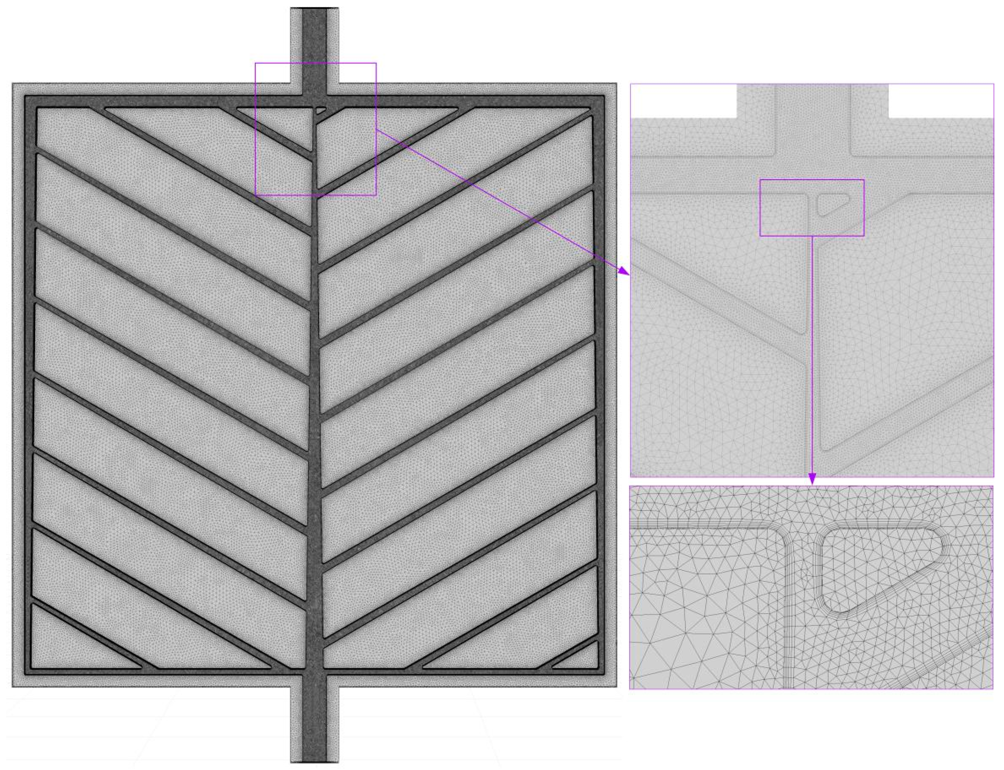
The commonly utilized manufacturing materials for MCHSs include aluminum and copper, with the former possessing a low density and the latter exhibiting high thermal conductivity. In terms of single-phase liquid cooling, water, antifreeze, fluorinated liquids, etc., are frequently employed as common fluids. Here, copper was chosen as the solid phase, while water was employed as the fluid phase.
The inlet temperature of the water was regulated to 20 °C, and a uniform inlet velocity was maintained. A pressure-based outlet with a gauge pressure of 0 Pa was utilized for the outlet boundary condition. The heat flux at the bottom wall of each MCHS was set to constant values (20, 50 and 80 kW/m2), whereas the remaining walls were configured as nonslip adiabatic surfaces.

3.4. Meshing

The generation of the computational mesh for the physical model of MCHSs was accomplished using ANSYS Meshing. Taking the PIN III model as an example, Figure 3 depicts an unstructured grid for both the fluid and solid domains. The unstructured mesh consists of tetrahedra and triangular prisms. To more accurately capture the complex flow phenomena near the wall, it is essential to implement grid encryption.
To further investigate the impact of the mesh quantity on the calculation outcomes, a comprehensive analysis was conducted using four different mesh quantities, as outlined in Table 2. The aim was to ensure that the chosen mesh quantity would not significantly affect the accuracy and reliability of the results. Upon decreasing the mesh quantity from 41.77 million to 24.84 million, various parameters were closely examined for any noticeable changes. It was observed that all the key indicators, including the maximum heating wall temperature (Tmax), standard deviation of the heating wall temperature (Tσ), Nusselt number (Nu), and friction factor (f), exhibited absolute change rates below 3.5%. Considering both computational efficiency and result accuracy, a final decision was made to select a mesh quantity of 24.84 million for subsequent calculations. This choice strikes an optimal balance between achieving reliable results while minimizing the computational resources needed.

3.5. Solution Strategy

The solution of the governing equations was carried out using ANSYS Fluent 2019 R1. The governing equations were discretized employing the second-order upwind method, with a pressure-based solver employed. The velocity and pressure were coupled via the SIMPLE method. The residuals of the continuity equation, momentum equation, and energy equation were set to 1 × 10⁻⁴, 1 × 10⁻⁴, and 1 × 10⁻⁶, respectively.

3.6. Data Reduction

The MCHS inlet section is rectangular, and the inlet Reynolds number (Re) can be calculated as
R e = ρ f u i n u D h μ f
where uin is the flow velocity and Dh denotes the hydraulic diameter.
The convective heat transfer coefficient (h) is defined as
h = q T w T f
where q denotes the heat flux, Tw represents the wall temperature at the solid–liquid interface, and Tf denotes the average temperature of the fluid.
T f = T i n + T o u t 2
The Nusselt is defined as
N u = h D h λ f
For an MCHS, it is imperative to not only focus on the maximum heating wall temperature (Tmax), which reflects the worst-case scenario of the performance under specific operating conditions but also address the uniformity of the heating wall temperature. To quantify this aspect, the parameter of wall temperature standard deviation (Tσ) was chosen. The calculation method for this parameter is as follows [13]:
T σ = A 0 T T a v g 2 d A A 0 d A
where A0 represents the heating wall area, and Tavg denotes the average temperature of the heating wall.
The Darcy–Weisbach friction factor (f) is defined as
f = 2 Δ p D h ρ f L u i n 2
where Δp is the pressure drop, and L is the length of the main channel (40 mm).

4. Results and Discussion

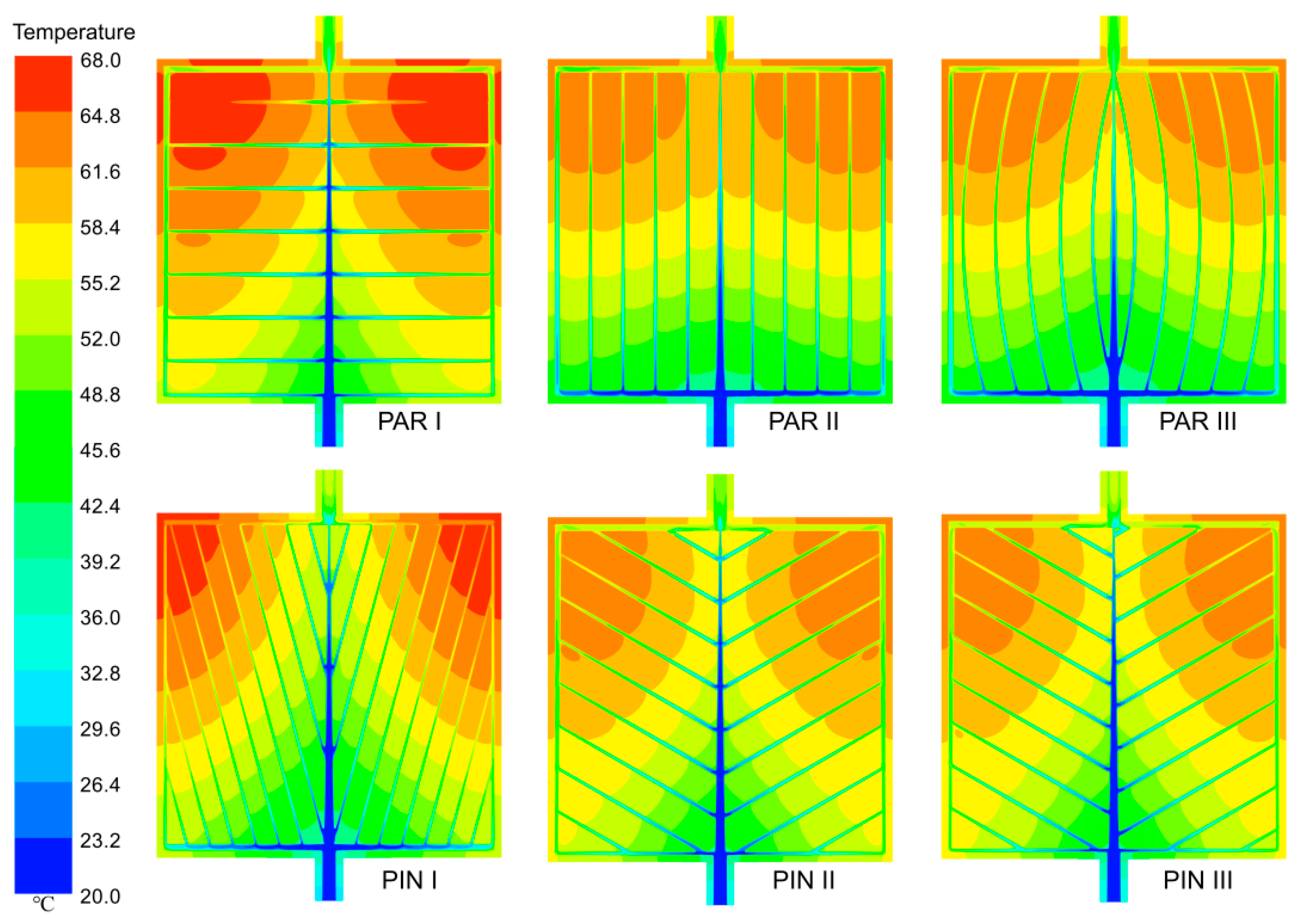
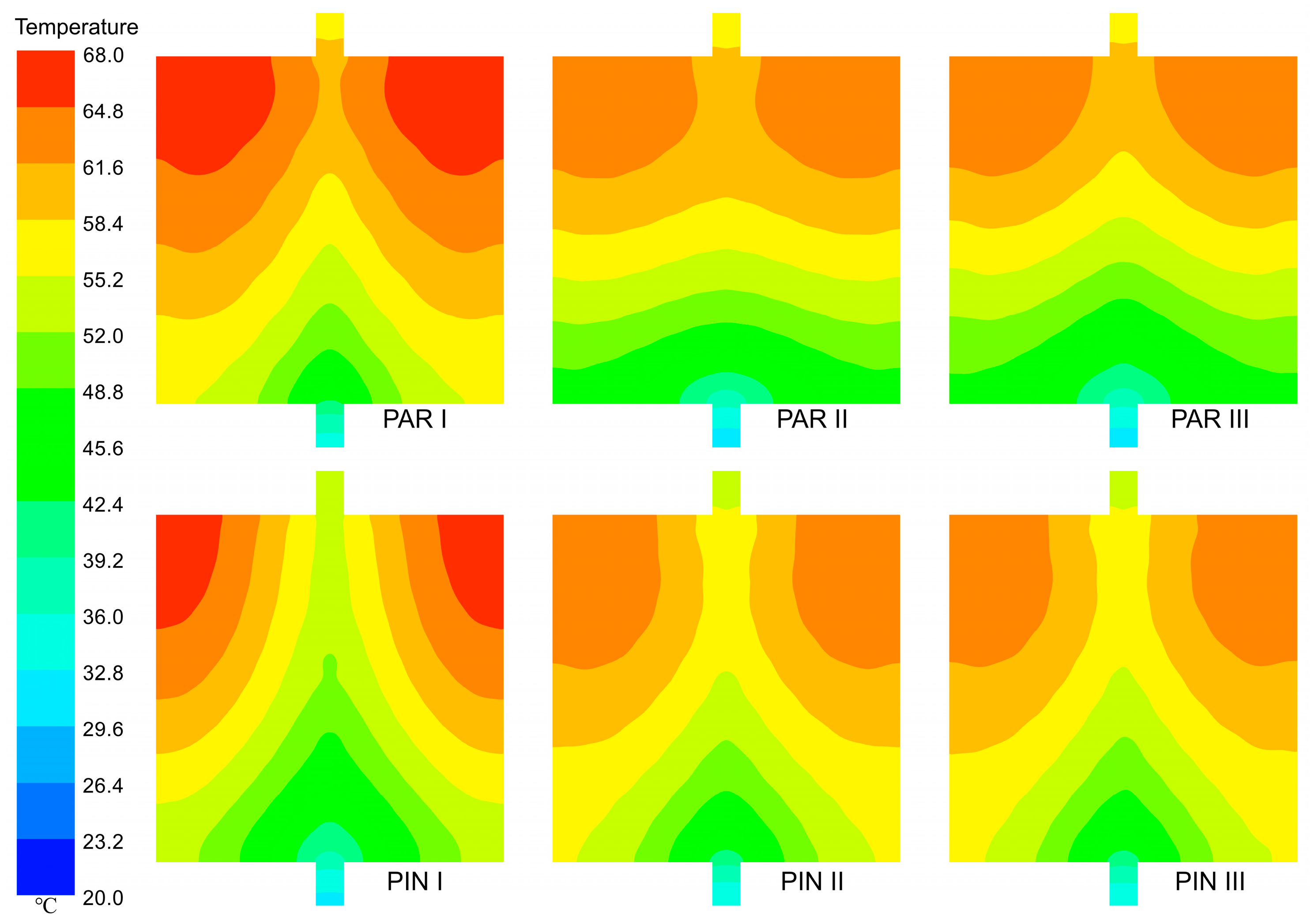
4.1. Effect of Leaf-Vein Structure

The influence of various leaf-vein structures on the thermal-hydraulic characteristics of MCHSs was investigated under the conditions of q = 50 kW/m2 and H = 0.8 mm. As illustrated in Figure 4a, within the range of Re examined, the Nu value of the PAR II MCHS is the highest, while that of PIN I is the lowest. The larger Re is, the larger Nu is. For the PAR II MCHS, the Nu value increases from 8.51 to 17.75 as Re increases from 400 to 1600; for PIN I, the Nu value ranges from 5.59 to 12.41. As illustrated in Figure 4b, PIN I exhibits the highest Tmax, while the other models exhibit more similar values. At a Re of 400, the Tmax value for the PIN I MCHS reaches 340.31 °C, whereas at a Re of 1600, it attains 310.83 °C. As illustrated in Figure 4c, within the Re range examined, the MCHS with the minimal Tσ is PIN III, while the maximum is PAR III. As Re increases from 400 to 1600, the Tσ of PIN III decreases from 4.30 to 1.58. As illustrated in Figure 4d, the f of the PAR III MCHS is minimal, whereas that of PAR I is maximal. When Re equals 400, f is 0.37; when Re reaches 1600, f reduces to 0.15.
The indicators of various MCHSs at Re = 1000 are presented in Table 3. Among them, PAR II and PIN III exhibit the highest Nu with values of 14.59 and 13.26, indicating their superior heat transfer performance. On the other hand, in regard to Tmax, PIN III and PAR II show the lowest readings with values of 315.09 and 315.11, respectively. This suggests that these two MCHSs have a better ability to maintain lower maximum temperatures compared to others. Furthermore, the Tσ value for PIN III is the lowest among all the MCHSs, which is 2.21 °C. In terms of the friction factor (f), PAR II ranks second lowest among all of the MCHSs considered with a value of 0.26. A lower f value implies a reduced pressure drop, which can lead to energy savings and improved overall efficiency. Considering all of these factors together, it becomes evident that both PAR II and PIN III demonstrate optimal results in regard to their combined performance.
The temperature contours at the top and bottom of the six MCHSs at q = 50 kW/m2 and H = 0.8 mm are presented in Figure 5 and Figure 6, respectively. Note that the contours are obtained via Ansys CFD-Post 2019 R1. The temperature gradually increases from the inlet to the outlet for all heat sinks, indicating a progressive heating process as the fluid flows through them. Interestingly, lower temperatures are found near the main channel compared to those in the branch channels. This can be attributed to a higher flow rate and increased convective heat transfer in the main channel, leading to more efficient cooling.
In terms of different flow structures, distinct variations in the temperature distribution can be observed. In the PAR flow structure, it is noteworthy that PAR II exhibits the lowest temperature among all the heat sinks. Among the PIN structures, PIN III stands out with its lowest temperature, while PIN II closely approximates it.
Additionally, interesting observations can be made regarding two right angles close to the outlet region in all MCHSs due to their square shape and arrangement of inlets/outlets along an intermediate axis. Significantly higher temperatures are observed near these angles, suggesting potential areas of concern for localized hotspots or reduced cooling efficiency.

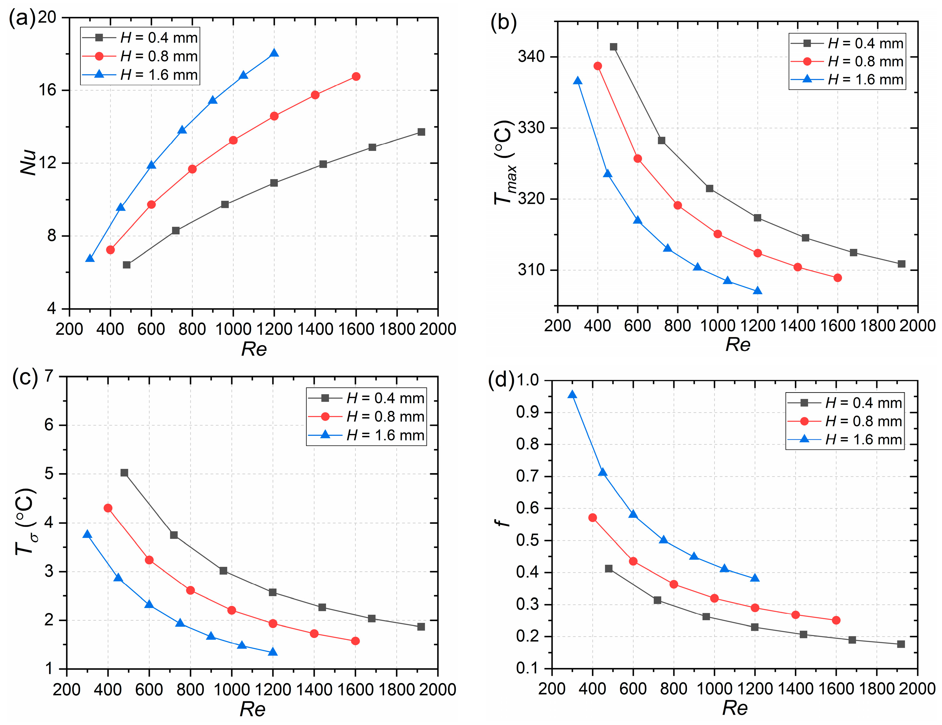
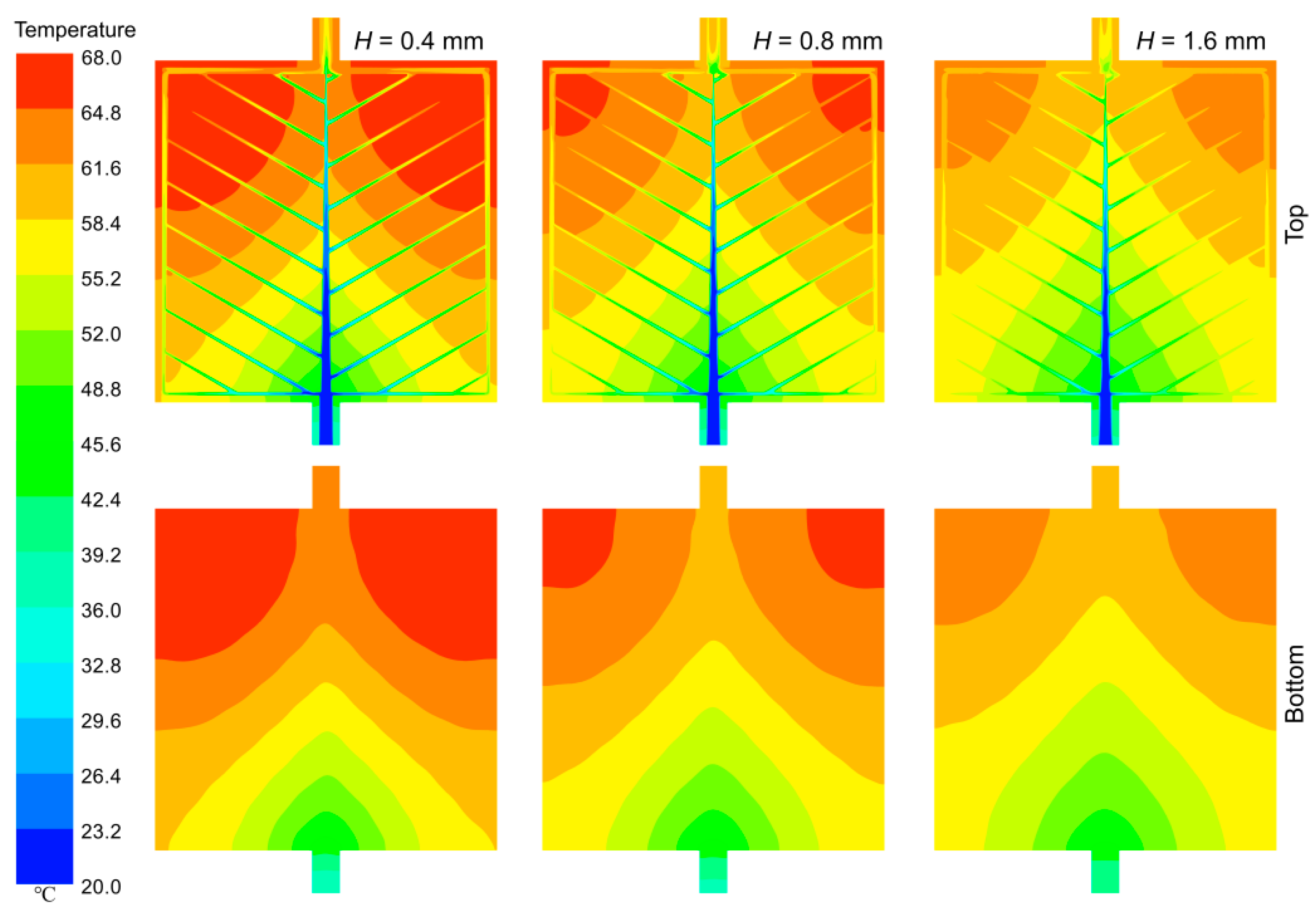
4.2. Effect of Channel Depth

Illustrating the PIN III MCHS as an example, this study delved into the heat transfer characteristics of various MCHS configurations, including those with channel depths of 0.4, 0.8, and 1.6 mm. The findings presented in Figure 7 demonstrate that within the studied Re range, an increase in channel depth results in a corresponding increase in Nu, a decrease in Tmax, and a decrease in Tδ, along with an increase in f. These results suggest that augmenting the depth of microchannels has a positive impact on enhancing Tmax and Tδ, albeit at the expense of compromised resistance performance.
The temperature contours of the top and bottom walls of the PIN III MCHS are presented in Figure 8 for q = 50 kW/m2 and Re = 1000, revealing a gradual decrease in temperature with increasing H.
It is noteworthy that certain studies have focused on comparing the influence of channel width to ensure a constant heat flux corresponding to the fluid contact area, whereas this study specifically emphasizes maintaining a predetermined heat flux at the heating surface, which aligns with frequent observations in practical applications.

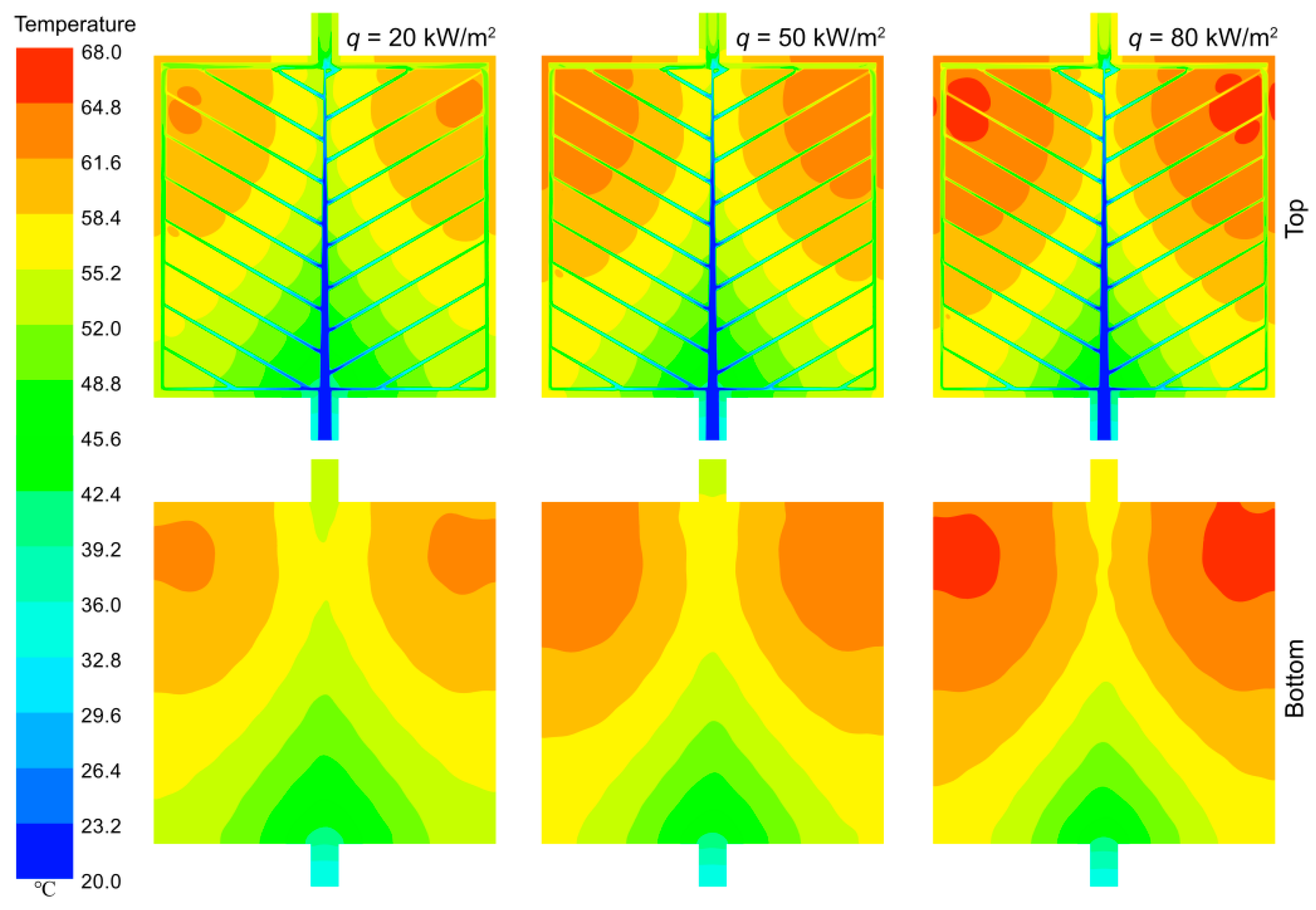
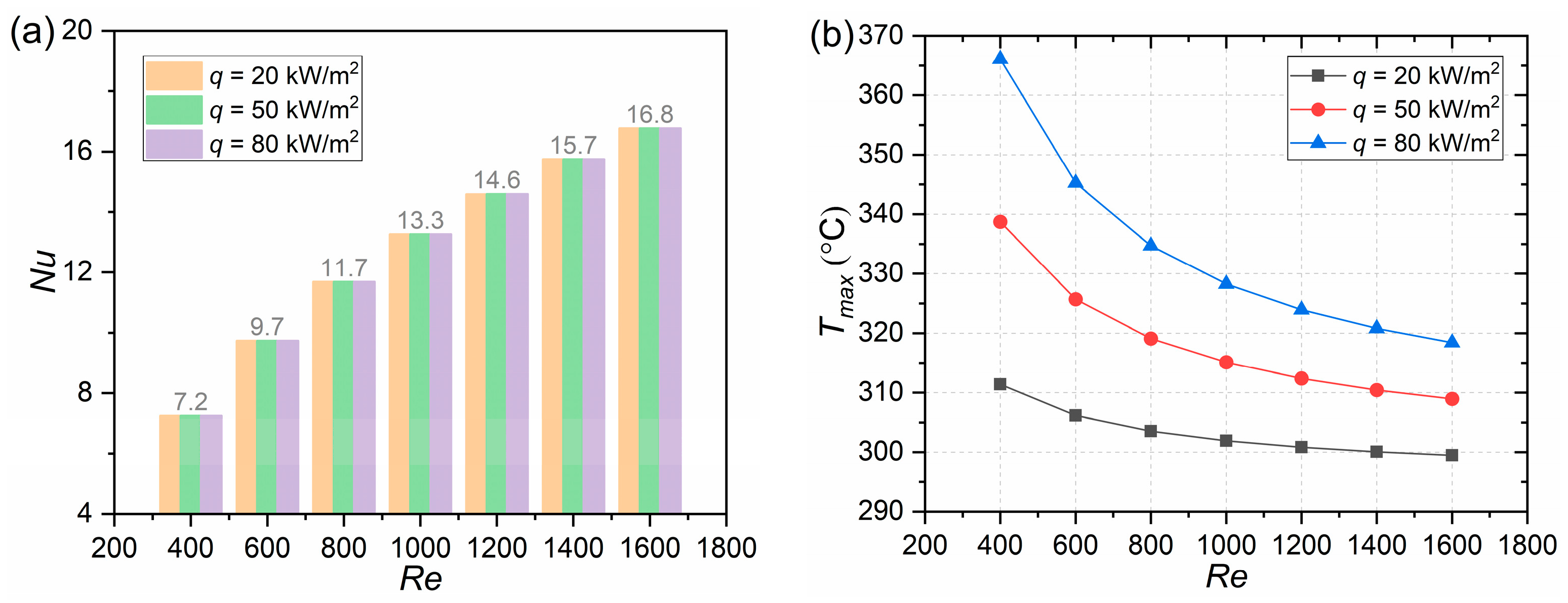
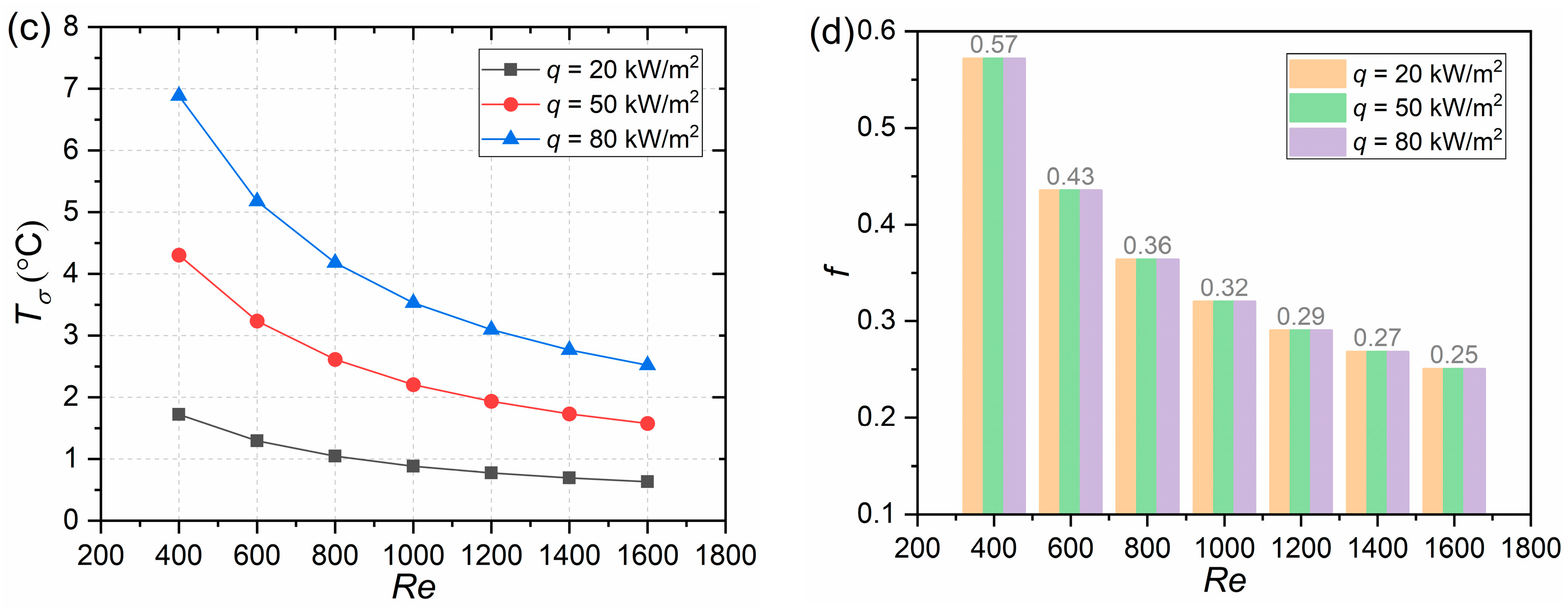
4.3. Effect of Heat Flux

As an example, the heat flux of the heating wall in the PIN III heat sink was set to 20, 50, and 80 kW/m2. The influence of the heat flux on heat sink performance was investigated under the same Re. As illustrated in Figure 9, the heat flux does not affect Nu. When Re ranges from 400 to 1600, the Nu values for the heat sink are 7.24, 9.73, 11.68, 13.26, 14.59, 15.75, and 16.77. With the increase in the heat flux, Tmax also rises, along with an increase in Tδ. In addition, the heat flux has no impact on f.
The temperature contours of the top and bottom walls of the PIN III MCHS are presented in Figure 10 for H = 0.8 mm and Re = 1000. It clearly demonstrates a gradual increase in temperature with the increment in the heat flux.
This observation suggests that variations in the heat flux have no discernible impact on the cooling efficiency and pump power consumption of MCHSs, whereas they do exert an influence on the temperature. Certainly, to meet the uniform temperature requirements, a higher heat flux necessitates an increased flow rate and subsequently leads to greater pump power consumption.

5. Conclusions

Inspired by the intricate patterns of leaf veins, six MCHSs with distinct structures were meticulously designed. Through rigorous numerical simulation, an in-depth investigation was conducted to explore the thermal-hydraulic characteristics of these MCHSs while also examining the influence of channel depth (H = 0.4, 0.8 and 1.6 mm) and heat flux (q = 20, 50 and 80 kW/m2) on their overall performance. The key findings are as follows:
(1)
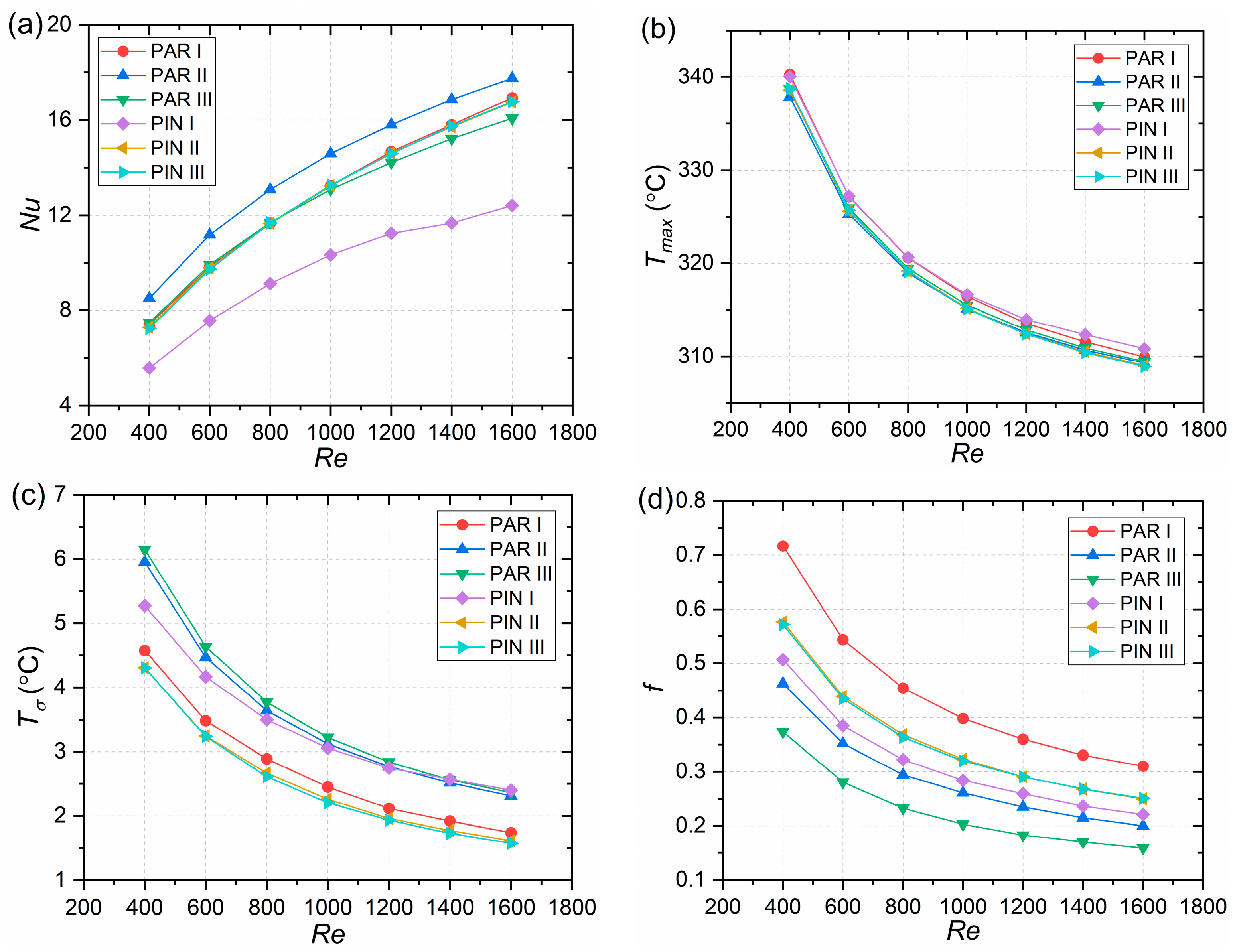
Among the six vein configurations, PAR II and PIN III exhibited the highest Nu with values of 14.59 and 13.26 at q = 50 kW/m2, H = 0.8 mm, and Re = 1000, respectively, while PIN III and PAR II demonstrated the lowest Tmax with values of 315.09 and 315.11 K, respectively. Additionally, PIN III displayed the lowest Tσ with a value of 2.21 °C, whereas PAR II had the second lowest f with a value of 0.26. Consequently, a combination of PAR II and PIN III yielded superior overall performance.
(2)
An increase in channel depth results in an increase in Nu, a decrease in Tmax and Tσ, and an increase in f. Augmenting the channel depth can enhance heat transfer; however, this increase comes at the expense of increased flow resistance. Moreover, a higher heat flux led to an amplification of Tmax and Tσ without affecting Nu or f.
(3)
For MCHSs such as the squares used in this study with a single inlet–outlet configuration, addressing local overheating near right angles close to the outlet to prevent excessive Tmax is an important area for further investigation.
(4)
The present study offers valuable insights into the optimization of various MCHS designs for specific applications based on their thermal-hydraulic properties. By comprehending these factors, more efficient cooling solutions can be devised.

Author Contributions

Conceptualization, Y.X.; methodology, J.W; software, S.Q.; validation, Y.X.; formal analysis, J.W. and S.Q.; investigation, J.W.; resources, Y.X.; data curation, J.W. and S.Q.; writing—original draft preparation, J.W.; writing—review and editing, Y.X.; visualization, S.Q.; supervision, Y.X.; project administration, Y.X.; funding acquisition, Y.X. All authors have read and agreed to the published version of the manuscript.

Funding

This research was funded by National Natural Science Foundation of China (52372331); Aeronautical Science Foundation of China (20182852024); China Postdoctoral Science Foundation (2020M671487); Research Fund of Key Laboratory of Aircraft Environment Control and Life Support, MIIT, Nanjing University of Aeronautics and Astronautics (KLAECLS-E-202307); and the Priority Academic Program Development of Jiangsu Higher Education Institutions.

Data Availability Statement

Data are contained within the article.

Acknowledgments

We sincerely acknowledge the Key Laboratory of Aircraft Environment Control and Life Support of MIIT for providing laboratory space.

Conflicts of Interest

The authors declare no conflicts of interest.

Nomenclature

A0heating wall area [m2]
cpspecific heat [J/kg K]
Dhhydraulic diameter [m]
fDarcy–Weisbach friction factor [–]
hheat transfer coefficient [W/m2 K]
Llength [m]
NuNusselt number [–]
ppressure [Pa]
qheat flux [W/m2]
ReReynolds number [–]
Ttemperature [°C]
uvelocity [m/s]
Δppressure drop [Pa]
Greek symbols
ρdensity [kg/m3]
λthermal conductivity [W/m K]
μviscosity [Pa·s]
Subscripts
avgaverage
ffluid
ininlet
outoutlet
ssolid
wwall

References

  1. Deng, T.; Zhang, G.; Ran, Y.; Liu, P. Thermal performance of lithium ion battery pack by using cold plate. Appl. Therm. Eng. 2019, 160, 114088. [Google Scholar] [CrossRef]
  2. Akbarzadeh, M.; Jaguemont, J.; Kalogiannis, T.; Karimi, D.; He, J.; Jin, L.; Xie, P.; Van Mierlo, J.; Berecibar, M. A novel liquid cooling plate concept for thermal management of lithium-ion batteries in electric vehicles. Energy Convers. Manag. 2021, 231, 113862. [Google Scholar] [CrossRef]
  3. Sakanova, A.; Tong, C.F.; Nawawi, A.; Simanjorang, R.; Tseng, K.J.; Gupta, A.K. Investigation on weight consideration of liquid coolant system for power electronics converter in future aircraft. Appl. Therm. Eng. 2016, 104, 603–615. [Google Scholar] [CrossRef]
  4. Zilio, C.; Righetti, G.; Mancin, S.; Hodot, R.; Sarno, C.; Pomme, V.; Truffart, B. Active and passive cooling technologies for thermal management of avionics in helicopters: Loop heat pipes and mini-Vapor Cycle System. Therm. Sci. Eng. Prog. 2018, 5, 107–116. [Google Scholar] [CrossRef]
  5. Wang, J.; Liu, X.; Liu, F.; Liu, Y.; Wang, F.; Yang, N. Numerical optimization of the cooling effect of the bionic spider-web channel cold plate on a pouch lithium-ion battery. Case Stud. Therm. Eng. 2021, 26, 101124. [Google Scholar] [CrossRef]
  6. Neumann, H.; Gamisch, S.; Gschwander, S. Comparison of RC-model and FEM-model for a PCM-plate storage including free convection. Appl. Therm. Eng. 2021, 196, 124079. [Google Scholar] [CrossRef]
  7. Xu, Y.; Li, L.; Wang, J. Experimental and numerical investigations of the thermal–hydraulic characteristics of novel micropin-fin heat sinks. Int. J. Heat Mass Transf. 2023, 209, 124079. [Google Scholar] [CrossRef]
  8. Huang, Z.; Hwang, Y.; Radermacher, R. Review of nature-inspired heat exchanger technology. Int. J. Refrig. 2017, 78, 1–17. [Google Scholar] [CrossRef]
  9. Asadi, A.; Pourfattah, F. Effects of constructal theory on thermal management of a power electronic system. Sci. Rep. 2020, 10, 21436. [Google Scholar] [CrossRef] [PubMed]
  10. Peng, Y.; Yang, X.; Li, Z.; Li, S.; Cao, B. Numerical simulation of cooling performance of heat sink designed based on symmetric and asymmetric leaf veins. Int. J. Heat Mass Transf. 2021, 166, 120721. [Google Scholar] [CrossRef]
  11. Xia, L.; Yu, Z.; Xu, G.; Ji, S.; Sun, B. Design and optimization of a novel composite bionic flow field structure using three-dimensional multiphase computational fluid dynamic method for proton exchange membrane fuel cell. Energy Convers. Manag. 2021, 247, 114707. [Google Scholar] [CrossRef]
  12. Alnaqi, A.A. Numerical analysis of pressure drop and heat transfer of a Non-Newtonian nanofluids in a Li-ion battery thermal management system (BTMS) using bionic geometries. J. Energy Storage 2022, 45, 103670. [Google Scholar] [CrossRef]
  13. Deng, T.; Ran, Y.; Zhang, G.; Yin, Y. Novel leaf-like channels for cooling rectangular lithium ion batteries. Appl. Therm. Eng. 2019, 150, 1186–1196. [Google Scholar] [CrossRef]
  14. Chen, Y.; Zhang, C.; Shi, M.; Yang, Y. Thermal and hydrodynamic characteristics of constructal tree-shaped minichannel heat sink. AIChE J. 2009, 56, 2018–2029. [Google Scholar] [CrossRef]
  15. Wang, X.-Q.; Xu, P.; Mujumdar, A.S.; Yap, C. Flow and thermal characteristics of offset branching network. Int. J. Therm. Sci. 2010, 49, 272–280. [Google Scholar] [CrossRef]
  16. Tan, H.; Wu, L.; Wang, M.; Yang, Z.; Du, P. Heat transfer improvement in microchannel heat sink by topology design and optimization for high heat flux chip cooling. Int. J. Heat Mass Transf. 2019, 129, 681–689. [Google Scholar] [CrossRef]
  17. Yenigun, O.; Cetkin, E. Experimental and numerical investigation of constructal vascular channels for self-cooling: Parallel channels, tree-shaped and hybrid designs. Int. J. Heat Mass Transf. 2016, 103, 1155–1165. [Google Scholar] [CrossRef]
  18. Han, X.-h.; Liu, H.-l.; Xie, G.; Sang, L.; Zhou, J. Topology optimization for spider web heat sinks for electronic cooling. Appl. Therm. Eng. 2021, 195, 117154. [Google Scholar] [CrossRef]
  19. Tan, H.; Du, P.; Zong, K.; Meng, G.; Gao, X.; Li, Y. Investigation on the temperature distribution in the two-phase spider netted microchannel network heat sink with non-uniform heat flux. Int. J. Therm. Sci. 2021, 169, 107079. [Google Scholar] [CrossRef]
  20. Qasemi, E.; Mahdavinejad, M.; Aliabadi, M.; Zarkesh, A. Leaf venation patterns as a model for bioinspired fog harvesting. Colloids Surf. A Physicochem. Eng. Asp. 2020, 603, 125170. [Google Scholar] [CrossRef]
Figure 1. Leaf venation: (a) parallel; (b) pinnate and reticulate; (c) dichotomous.
Energies 17 00311 g001
Figure 2. Physical model of six MCHSs: (a) PAR I; (b) PAR II; (c) PAR III; (d) PIN I; (e) PIN II; (f) PIN III.
Energies 17 00311 g002
Figure 3. Computational mesh.
Energies 17 00311 g003
Figure 4. Performance of various MCHSs: (a) Nu; (b) Tmax; (c) Tσ; (d) f.
Energies 17 00311 g004
Figure 5. Top temperature contours of various MCHSs at Re = 1000.
Energies 17 00311 g005
Figure 6. Bottom temperature contours of various MCHSs at Re = 1000.
Energies 17 00311 g006
Figure 7. Effect of channel depth on the performance of the PIN III MCHS: (a) Nu; (b) Tmax; (c) Tσ; (d) f.
Energies 17 00311 g007
Figure 8. Temperature contours of the PIN III MCHS with different channel heights at Re = 1000.
Energies 17 00311 g008
Figure 9. Effect of heat flux on the performance of the PIN III MCHS: (a) Nu; (b) Tmax; (c) Tσ; (d) f.
Energies 17 00311 g009aEnergies 17 00311 g009b
Figure 10. Temperature contours of the PIN III MCHS with different heat fluxes at Re = 1000.
Energies 17 00311 g010
Table 1. Synopsis of the flow area data for various MCHSs.
MCHSLiquid Area Ratio aSolid–Liquid Contact Area (mm2)
PAR I14.47%942.99
PAR II14.74%1015.09
PAR III16.46%1148.48
PIN I16.30%1386.75
PIN II14.98%1032.30
PIN III15.00%1033.15
a It is the ratio of the bottom area of the flow channel to that of the heat sink.
Table 2. Numerical results at different mesh quantities.
Mesh QuantityTmax (°C)Tσ (°C)Nuf
2.484 × 107315.162.2613.230.32
3.130 × 107314.932.2513.500.32
3.470 × 107314.832.2713.660.32
4.177 × 107314.862.3013.680.32
Table 3. Summary of characteristics of various MCHSs at Re = 1000.
MCHSNuTmax (K)Tσ (°C)f
PAR I13.24316.442.450.40
PAR II14.59315.113.120.26
PAR III13.08315.513.220.20
PIN I10.34316.623.060.28
PIN II13.23315.162.260.32
PIN III13.26315.092.210.32
Disclaimer/Publisher’s Note: The statements, opinions and data contained in all publications are solely those of the individual author(s) and contributor(s) and not of MDPI and/or the editor(s). MDPI and/or the editor(s) disclaim responsibility for any injury to people or property resulting from any ideas, methods, instructions or products referred to in the content.

