Article

Analysis of Operational Problems and Improvement Measures for Biomass-Circulating Fluidized Bed Gasifiers †

1
Nanxun Innovation Institute, Zhejiang University of Water Resources and Electric Power, Hangzhou 310018, China
2
College of Metrology and Measurement Engineering, China Jiliang University, Hangzhou 310018, China
3
China Energy Engineering Group Zhejiang Electric Power Design Institute Co., Ltd., Hangzhou 310012, China
*
Author to whom correspondence should be addressed.
This paper is an extended version of our paper published in E3S Web of Conferences 329,01040, 4th International Conference on Green Energy and Sustainable Development (GESD 2021), Shenyang, China, 10–11 July 2021; pp. 1–5.
Energies 2024, 17(2), 303; https://doi.org/10.3390/en17020303
Submission received: 16 November 2023 / Revised: 25 December 2023 / Accepted: 4 January 2024 / Published: 7 January 2024
(This article belongs to the Special Issue Biomass Conversion Technologies II)

Abstract

:
The advancement of biomass-circulating fluidized bed (CFB) gasification technology in China for commercialization and industrial application is still in its initial stages, characterized by extensive theoretical studies; however, there is limited documentation of its actual industrial operational characteristics. This study analyzes the operational challenges encountered in a 5 t/h biomass CFB gasifier at a rice factory in Jiangsu Province, China. It examines critical issues emerging during the gasifier system’s actual operational process, including the obstruction of the feeding system, the measurement of pressure at point blockages in the dense phase zone, loop seal blockages, bed inventory leakage of the blast cap on the air distribution plate, and gasification parameter fluctuations. Practical improvement strategies and implementation plans are proposed to address these operational concerns. The outcomes of this analysis serve as a reference for the design and operation of biomass CFB gasifiers. Furthermore, they provide crucial guidance for more extensive large-scale implementation of biomass CFB gasifiers.

1. Introduction

Our excessive reliance on and exploitation of fossil fuels has led to environmental degradation and global warming. Consequently, the global focus has shifted significantly toward renewable energy sources. Biomass, recognized for its abundant availability and low environmental impact, stands as the foremost alternative to fossil fuels and a unique and renewable source of carbon [1]. Among the various technologies for utilizing biomass, biomass gasification is considered one of the cleanest. However, substantial advancements are crucial for its larger-scale commercial deployment. Biomass gasification, recognized as a CO2-neutral substitute for fossil fuels, offers diverse applications, ranging from power generation through combustion engines [2] or fuel cells [3] to producing various liquid or gaseous biofuels and chemical products using syngas [4,5]. Biomass gasification can be classified into two main types: fixed-bed and fluidized-bed gasification. Compared with a fixed-bed gasifier, the fluidized-bed gasifier, particularly the circulating fluidized-bed (CFB) gasifier, exhibits higher gasification capacity, higher conversion efficiency, a higher calorific value of gas, and greater suitability for continuous operation; it exhibits tremendous potential for large-scale applications, marking the trajectory for future advancements [6].
The exploration of biomass fluidized-bed gasification technology started earlier and progressed more rapidly in Europe and the United States. Timsina et al. [7] conducted experiments in a bubbling fluidized-bed gasifier, employing two biomass feedstocks, wood and grass. Their findings highlighted the frequent occurrence of caking phenomena during grass gasification when temperatures exceeded 800 °C. Additionally, the gasification of grass pellets yielded a lower carbon conversion rate compared with that of wood particles. Specifically, the carbon conversion from wood particle gasification reached approximately 60% at 850 °C. Myohanen et al. [8] conducted a numerical study of the reaction process within the CFB gasifier. They constructed a gas–combustion chamber coupling system using waste wood as fuel to simulate gasification reactions, analyzing fluid flow and heat transfer. Muhammad et al. [9] established the Reynolds mean Navier–Stokes equation, a vortex crack combustion model, and a modified k−ϵ model to forecast the temperature distribution and flow field in the gasifier, using wood particles as raw materials. Their analysis involved assessing various operating conditions, such as the number of air intakes, fuel air velocity, and moisture content in the feedstock, impacting the gasification outcomes. Von Berg et al. [10] employed a multi-scale modeling approach in a 1 MW industrial-scale fluidized-bed biomass gasifier. They merged a detailed one-dimensional particle model based on the progressive conversion model (PCM) with commercial CFD software ANSYS Fluent (V2021 R2) to exhibit the feasibility of PCM simulation in industrial-scale fluidized-bed biomass gasification.
Internationally, the biomass fluidized-bed gasification industry is predominantly concentrated in developed countries, especially Europe [11,12]. Existing biomass gasification devices are typically large in scale, highly automated, and entail complex processes. For example, in Finland, there are several CFB gasification plants in operation, such as Joutseno Mill, Lahti Energia Kymijarvi I, Lahti Valmet Kymijarvi II, Varkaus Stora Enso, and Aanekoski, whose technology is provided by Andritz, Valmet, Volter, and VTT, among others [13]. Amongst these, Kymijarvi II, located in Lahti, is the largest gasification plant currently operating in Europe, and has been in commercial operation for seven years [13]. The plant includes two 80 MWth atmospheric CFB gasifiers (installed by Valmet) and produces 50 MWe of electricity and 90 MWth of district heat [14]. The Essent/RWE wood waste gasifier is the largest plant in the Netherlands, and includes an 85 MWth CFB reactor based on Lurgi technology [15]. This infrastructure is connected to a 600 MWe coal-fired power plant that operated for about 5000 h per year from 2001 to 2013, interrupted by feeding problems and tar-related pollution [16]. Another large-scale gasification plant in the Netherlands was installed by ESKA at Hoogezand in 2016. The infrastructure is currently in operation and includes a 15 MWth CFB plant for the gasification of paper rejects from the manufacturing process of high-quality solid board [17]. The main objective is to produce fuel gas to replace natural gas in the solid board manufacturing process. In Sweden, the Varmlandsmetanol AB CFB gasification plant is awaiting investment (EUR 390 million), with 125 MWth CFB gasifiers and 130,000 m3/year of methanol output [18]. Another plant, Vaxjo Varnamo Biomass Gasification Center AB, has been put on hold; it includes an 18 MWth atmospheric CFB gasifier and produces 6 MWe of electricity and 8 MWth of district heat [19]. CFB gasification technology in the United States is more often applied for the preparation of biofuels. The fluidized-bed gasification of a bio-solids project in Linden, New Jersey, supplied by Aries Clean Energy, which began operating in 2021, processes 430 TPD biosolids; and 22 TPD biochar and power. The San Joaquin Renewables pressurized fluid-bed (10 Bar) project in San Joaquin, California, supplied by Frontline BioEnergy, is in the process of being engineered, and produces RNG from agricultural wastes [20]. Fluidized-bed gasifiers developed by Carbogas Company are designed to treat agricultural waste and municipal solid waste, and to generate electricity from biogas. The company has deployed dozens of units in South American countries such as Brazil [21]. There are only a few reports of biomass CFB gasification in Asia, such as the 157 kW project developed by Tokyo Gas Co., Ltd. (Tokyo, Japan) and Takuma Co., Ltd. (Kanagawa, Japan), in Tokyo and Kanagawa, respectively, in Japan. Most biomass gasification projects in Asia use small gasifiers such as Downdraft [12].
Research on biomass fluidized-bed gasification technology in China started comparatively later. The literature on the gasification characteristics of biomass CFB in China is primarily focused on small-scale benches or numerical simulations. Li Hongliang et al. [22] executed pyrolysis gasification of rice husks on a laboratory-scale fluidized bed, using water vapor as the gasification agent. The results indicated an increase in the gas component contents of CH4 and H2 with escalating temperatures. Additionally, the CO content exhibited an initial increase followed by a decline. The co-gasification behavior of straw and coal was investigated by Zengxi et al. [23] in a small fluidized bed. Their results indicated that the addition of straw to coal significantly enhanced CO production. Cao et al. [24] experimentally examined the gasification of wood chips in a fluidized-bed system, with coal bottom ash (CBA) as the bed material. Their study uncovered the production of H2-rich syngas from wood gasification, as well as a reduction in tar, both notably influenced by different CBA sizes. In addition, Cao et al. [25] investigated the co-gasification behavior of rice husk and blends of two woody biomasses, sawdust and bamboo dust in a CFB system using ASPEN plus software. Zhu et al. [26] numerically investigated biomass–CO2 gasification in a pilot plant CFB gasifier via a reactive multiphase particle-in-cell (MP-PIC) model. Gas–solid hydrodynamics and thermochemical characteristics under different percentages of CO2 in a gasifying agent were comprehensively analyzed.
The aforementioned studies predominantly occur on small and medium-sized platforms, lacking strong directives for the operation of actual large-scale and medium-sized gasification units. Operation at an industrial scale with large-scale gasifiers is a complicated process, fraught with uncertainties that can lead to operational failures or issues. Few studies exist based on pilot-scale test benches, offering limited guidance and reference for actual production. Meng et al. [27] conducted gasification tests under atmospheric pressure in a 100 kWth steam–oxygen blown CFB gasifier, using two woody biomass fuels, Agrol and willow, and one agriculture residue, Dry Distiller’s Grains with Solubles, as fuels. The effects of operational conditions (e.g., the steam-to-biomass ratio (SBR), oxygen-to-biomass stoichiometric ratio (ER), and gasification temperature) and bed materials on the composition distribution of the product gas and tar formation of these fuels were investigated. Xiaoxu Fan [28] conducted an air gasification test using cotton stalk pellets in a 0.02 MWt CFB gasifier. The experimental results indicated that bed agglomeration would occur after a period running with sand, high-alumina bauxite, or periclase as the bed material at 600–800 °C, and potassium gathered on the surface of bed materials. Zeng et al. [29] investigated the fluidized bed pyrolysis gasification process of Chinese medicinal residue, and undertook an industrial demonstration project to produce biomass gas with low tar content.
Notably, the industrial application of fluidized-bed gasification in China is limited to systems such as biomass fluidized-bed gasification heating cogeneration carbon systems. For example, 8 t/h and 10 t/h fluidized-bed gasification heating co-production lines were implemented in 2016 and 2019 in Lishui City and Anji City in Zhejiang Province, respectively, using powdered bamboo chips as the raw material [30]. Moreover, in 2021, a rice factory in Jiangsu Province implemented 5 t/h fluidized-bed gasification heating co-production of a carbon line utilizing rice husks [31]. Larger applications are predominantly utilized in gasification-coupled large-scale coal-fired power generation systems. Notable examples include the transformation of a 640 MW coal power unit into a coal-coupled biomass power generation project at the Guodian Changyuan Jingmen Power Plant in 2012, employing indirect biomass co-firing technology [32]. Additionally, the Datang Changshan Thermal Power Plant operates the largest-capacity biomass mixed-combustion generator set in China, using CFB micro-positive pressure air gasification and a 660 MW supercritical boiler for combustion [33]. Unit 6 of the Huadian Xiangyang Power Plant represents the first indirect biomass co-combustion generator set using straw as the primary raw material in China, inaugurated in 2018 [34,35].
However, the commercialization and industrialization of biomass-circulating fluidized bed gasification technology in China remain in their initial stages, characterized by a prevalence of experimental or theoretical studies and a scarcity of practical industrial applications. The verification of the feasibility and stability of numerous gasification technologies is imperative. Few reports exist on the gasification characteristics and operational attributes of large and medium-sized biomass fluidized beds under gasification conditions, owing to commercial and technical secrecy. Therefore, based on a 5 t/h biomass CFB gasifier in a rice factory in Jiangsu Province, this paper aims to summarize the operational issues and propose measures for improving the gasifier’s operation process. The objective is to furnish insights for the large-scale application and advancement of this gasifier type in China.

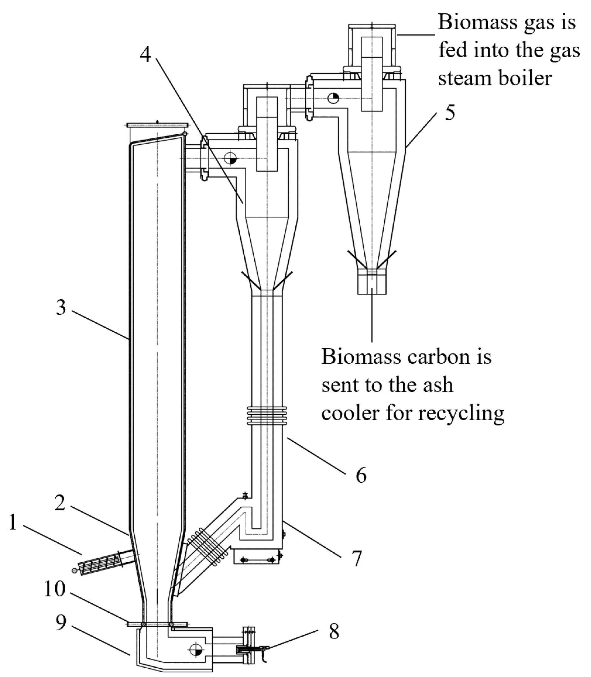
2. Equipment Overview

The biomass CFB gasifier, situated in a rice plant in Jiangsu Province, comprises a lower-density phase zone with a section size of 1.2 m × 1.2 m. The furnace wall slopes outward at a 30° angle, and gradually transitions to the dilute phase zone, which measures 1.8 m × 1.8 m. The gasifier stands at a total height of 18 m. Figure 1 presents the schematic diagram of the CFB gasifier system, and essential design parameters are summarized in Table 1. This gasifier employs a square furnace constructed with a membrane water wall and an external lining castable. The bottom of the furnace comprises a fluidized air chamber, and light diesel oil under the bed facilitates ignition. The system includes separate biomass and quartz sand feeding systems installed in front of the furnace. A two-stage adiabatic cyclone separator is positioned behind the furnace, with a loop seal placed under the primary cyclone separator to redirect materials back to the furnace. Below the secondary cyclone separator, the high-temperature ash recovery system cools and recycles the high-temperature ash. The high-temperature gas extracted from the upper part of the secondary cyclone separator is channeled into the gas steam boiler for combustion, producing saturated steam. Rice husk serves as the primary raw material, as indicated in Table 2. Quartz sand is used as the bed inventory.

3. Main Problems and Improvement Measures

3.1. Feed System Blockage

During the operation, the feed system of the gasifier is susceptible to material clogging, hindering the stable feed of biomass raw materials and causing significant fluctuations in feed quantity and load. Furthermore, gaps in the feeding process may lead to reduced sealing, primarily when the system operates under negative pressure, enabling air ingress through the feeder and disrupting the gasifier’s stable operation.
The structure of biomass raw materials, characterized by a loose structure and high fiber toughness, poses challenges for traditional screw conveyors. These conveyors, with an equal pitch structure, generate material compaction zones in the hopper [36], causing clogs in the feeding section, impeding material discharge and causing material compaction, resulting in unstable feeding system operation and jeopardizing the gasifier’s safe operation. Moreover, biomass materials, due to poor fluidity and significant voids, encounter issues with the horizontal layout of traditional screw conveyors, leading to air leakage and poor sealing in the system. This not only affects oxygen distribution in the gasifier, but also leads to tempering and potential biomass gas deflagration accidents.
To address these challenges, the following measures can be adopted:
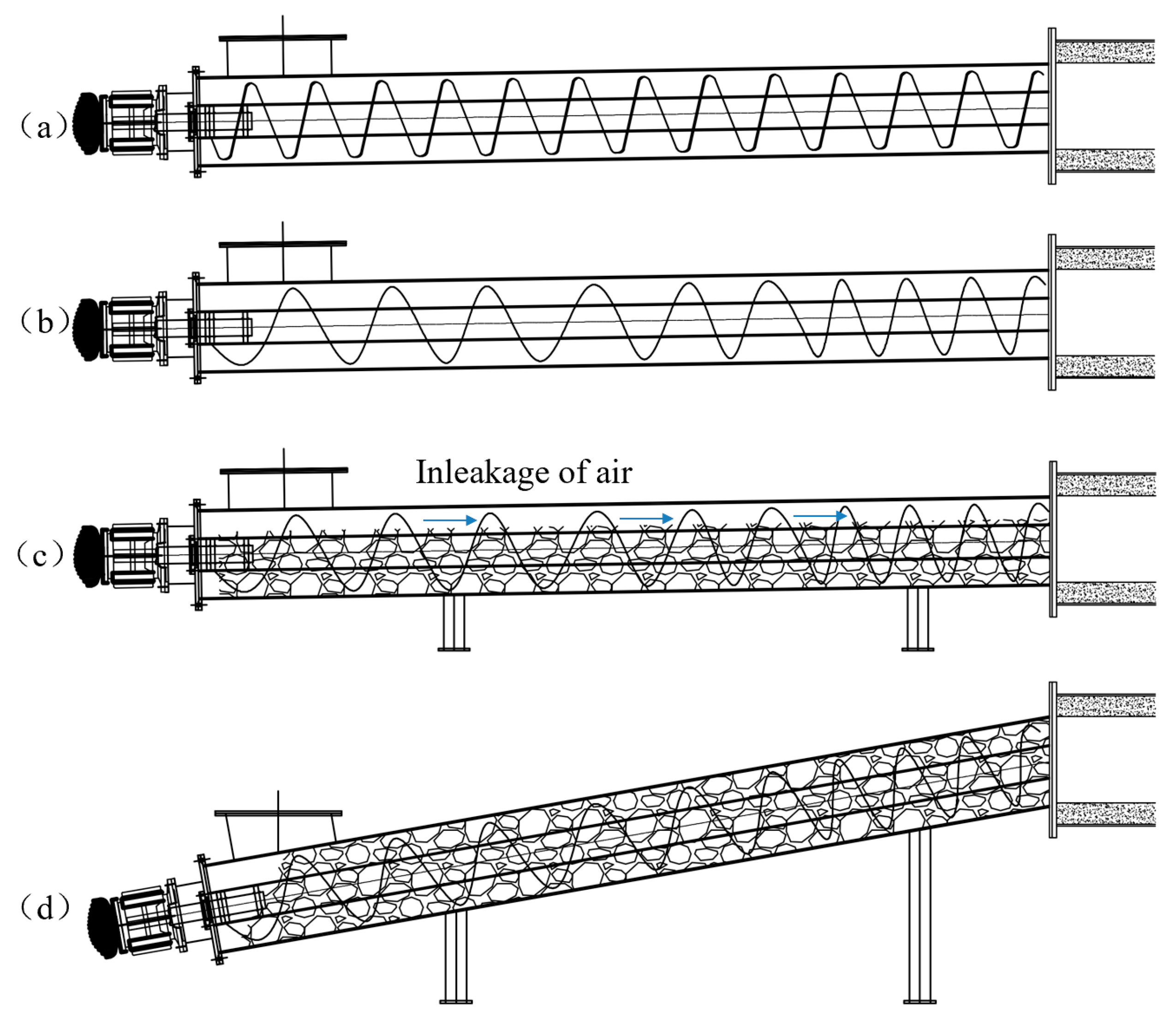
  • A variable pitch screw conveyor can be used as an alternative to the traditional constant pitch structure (as shown in Figure 2a,b). In addition, a variable pitch structure can be applied at the feed end to reduce the appearance of “dead zones” and ensure uniform material distribution by selecting equidistant screws in the final section of the variable pitch.
  • A negative inclination angle arrangement for the screw conveyor can be used instead of the original horizontal layout (as illustrated in Figure 2c,d). Under this measure, the feed end of the conveyor is elevated, and the discharge end closer to the gasifier side is lowered. This inclined layout maximizes material fill in the conveyor, reducing air leakage and effectively resolving issues related to weak sealing and tempering in the feeding system.

3.2. Measuring Pressure at Point Blockages in the Dense Phase Zone

During the operation of the gasifier, it was observed that certain pressure measuring points in the dense phase area were found to be blocked. This issue is commonplace during the commissioning process of CFB boilers, primarily due to the high material concentration in the dense phase zone, which easily clogs the pressure measuring points in the fluidization process, particularly during gasification, when the reaction temperature is slightly lower.
The primary measures to address this blockage in the dense phase zone are as follows:
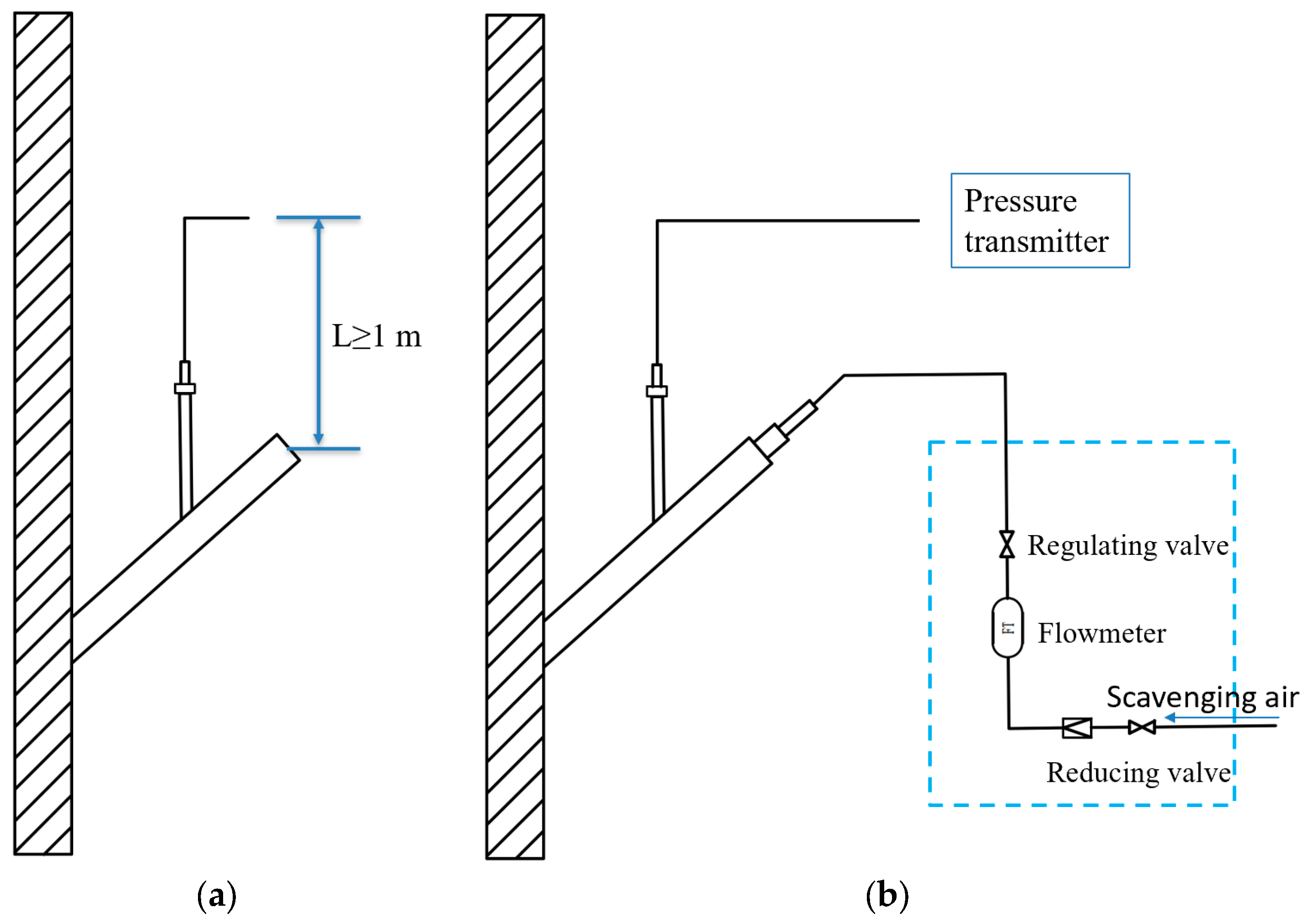
  • The positioning of the pressure sampling pipe must be inclined to prevent dust clogging caused by material entering the measurement pipe during operation. The pipe should include a vertical section upward of no less than 1 m during installation (Figure 3a).
  • The actual elevation of the sampling casing must be designed with consideration of the varying thickness of the gasifier wall in the dense phase zone before installation, in order to minimize installation height errors.
  • The purged air and a pressure compensator are incorporated at the pressure measuring point in the dense phase zone (Figure 3b). Regular or continuous purging of the air during gasifier operation prevents the blockage of the pressure measuring point.
  • The bed pressure correction value in the gasifier’s logic control system must be adjusted. The calculation relationship between the fluidization air volume and empty plate resistance is based on cold aerodynamic field test data. The discrepancy between the air chamber’s static pressure and the calculated value of the empty plate resistance serves as the bed pressure correction value, mitigating the influence of the blockage of the pressure measuring point in the dense phase zone during actual operation.

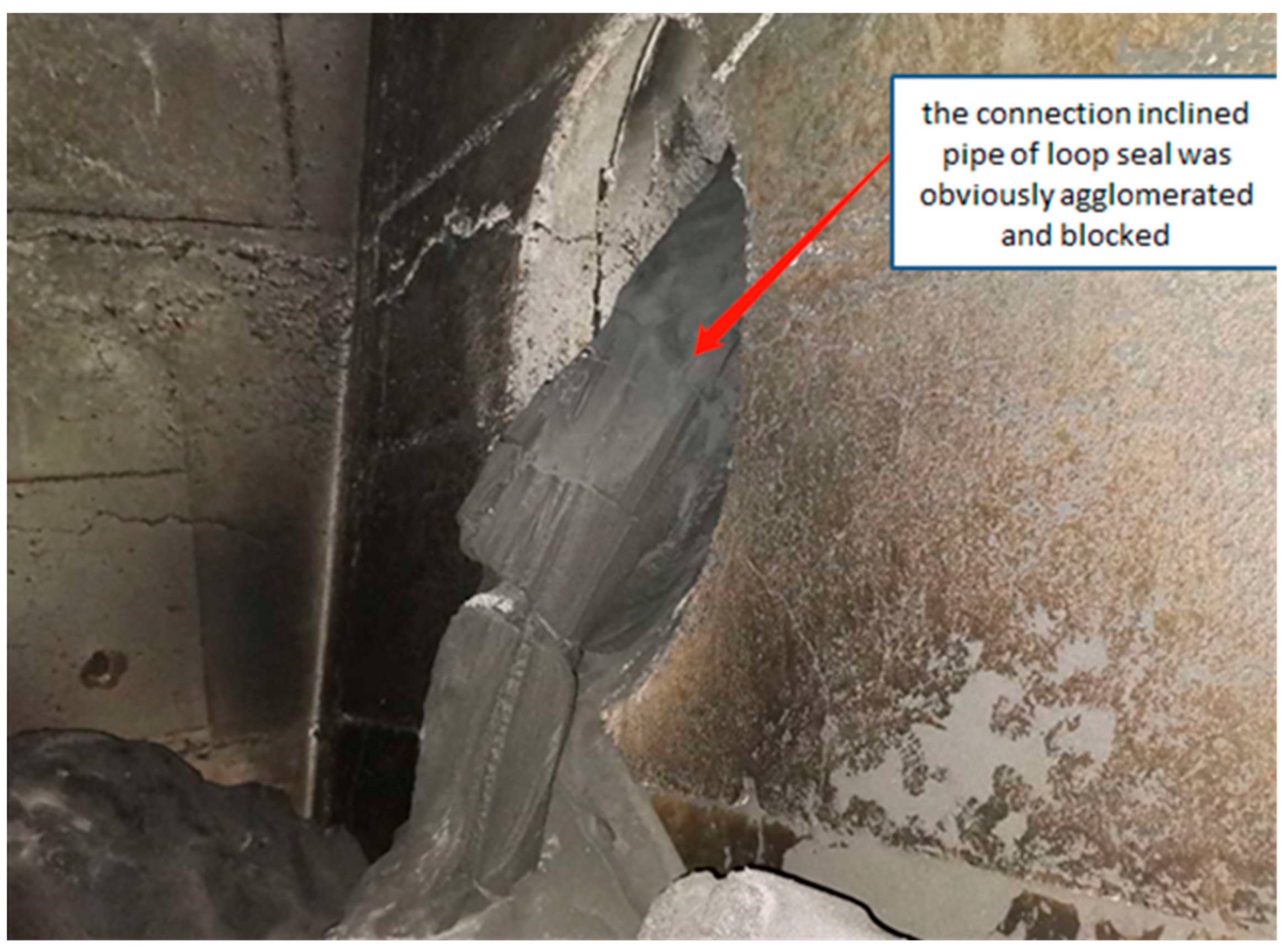
3.3. Loop Seal Blockage

The gasifier, following its shift from combustion to gasification, operated normally with the feeder output and gas steam boiler load. The subsequent sintering ash caused a blockage in the loop seal located beneath the main separator of the gasifier, resulting in abnormal return of the loop seal. The inclined pipe connecting to the loop seal showed evident agglomeration and blockage, as depicted in Figure 4.
The loop seal blockage primarily results from the secondary combustion of high-temperature ash and combustible gas, overheating the loop seal and leading to high-temperature ash sintering [37]. When superheated steam serves as the returning fluidizing medium, no ash coke forms in the steam’s purging section. Nevertheless, early or uneven injection of the returning steam may still cause coking and loop seal blockage. Premature steam injection causes condensation when hot steam meets cold materials, leading to rice husk ash bonding into blocks through water vapor action. Uneven steam injection results in some regions of rice husk ash remaining unpenetrated, leading to reburning and caking.
To address these challenges, the following measures can be adopted:
  • Air is used as the fluidization feedback medium in the gasifier during direct combustion, transitioning to high-temperature superheated steam in the loop seal before gasification. The material layer height of the loop seal is maintained, and the appropriate returning air or steam volumes must be controlled.
  • Steam nozzles are installed to ensure uniform injection. Six sets of steam nozzles are positioned approximately 200 mm above the loop seal caps, controlling the blowing angle and direction. Additionally, the steam pipeline is insulated, the steam hydrophobic position is varied, and the pressure of returning steam is increased to 0.4–0.5 MPa to ensure that the returning fluidization medium is steam, and to prevent water vapor precipitation.

3.4. Bed Inventory Leakage of Blast Cap on Air Distribution Plate

The gasifier furnace utilizes mushroom caps 6 mm in diameter on its air distribution plate for the blast cap. However, during operations, significant bed inventory leakage in the ignition air chamber became a severe issue. In more extreme cases, the bed inventory required replenishment over three times per operational shift, necessitating furnace cleaning during each shutdown.
The direct blowing design of the mushroom caps contributes to the leakage issue when the gasifier’s bed pressure fluctuates. Fine rice husk ash and bed inventory seep through the cap holes along with these pressure fluctuations, infiltrating the fluidization air chamber. Moreover, the repair and replacement of mushroom caps are inconvenient due to their integrated structure. The caps are welded to the air distribution plate and buried under refractory materials. Repairing or replacing caps requires breaking the refractory materials, leading to substantial maintenance costs.
The primary solution involves substituting the mushroom-shaped caps with bell-shaped caps, as depicted in Figure 5. The design of the bell caps includes a connecting pipe that extends into the cap’s top cover, preventing direct contact between the cap hole and the bed inventory. This transition effectively resolves the leakage issue associated with mushroom caps. Additionally, since the caps are not fixed within the refractory materials, replacing them involves solely removing the top cover without damaging the refractory materials, thereby saving time and reducing maintenance expenses [38].

3.5. Fluctuation of Gasification Condition

During gasifier operation, considerable fluctuations in gasification parameters are observed. For instance, on 23 September 2020, the gasifier experienced frequent fluctuations in bed temperature (ranging from 775–820 °C) and bed pressure (ranging from 1900 to 7500 Pa) without external load disturbances.
Uneven feed significantly contributes to these gasification parameter fluctuations [39]. The biomass feedstock, transferred to the pre-furnace silo via a belt conveyor and then fed into the furnace by a two-stage screw, exhibits characteristics of bridging, uneven winding, occasional fluffiness, denseness, and accumulation near the feed port. This biomass, being predominantly volatile, with a small fuel stock in the furnace, amplifies the impact of any feed fluctuation on gasification parameters. Discrepancies between feed and return amounts result in severe fluid imbalance within certain bed areas, a leading cause of bed pressure fluctuation. If the feed amount is excessively high, the thickness of the gasification charge layer is exceedingly high, resulting in poor fluidization and furnace coking or fire extinguishing [40].
The following measures can be adopted to resolve these issues:
  • Feed system optimization. The feed system must be optimized, extending the feed spiral toward the furnace and aligning it with the membrane wall to prevent biomass accumulation near the inlet. Additionally, a negative pressure state must be established near the feed port to prevent flue gas backchanneling.
  • The feeding speed must be controlled, and the increment of single-side feed must be maintained at 1–2% during the transition from combustion to gasification in the gasifier. The fuel and primary air volume must be increased sequentially to maintain stable furnace bed pressure and temperature.
  • The operational adjustment must be enhanced by controlling the feed amount and return air volume, resulting in rapid changes in bed temperature, pressure, and return valve. These changes can be predicted and adjusted to ensure gasifier stability during gasification or combustion.

4. Conclusions

This paper provides insights into the operation of a 5 t/h biomass-circulating fluidized-bed gasifier, presenting a series of improvement measures. For instance, employing a variable-pitch screw conveyor with a negative inclination angle addressed the issue of feed system blockage. This involved the optimization of sampling tube installation in the dense phase zone, and alleviation of blockages in the dense phase zone’s pressure measuring points. Furthermore, optimizing fluidization procedures and incorporating steam fluidization nozzles above the loop seal effectively resolved loop seal blockages during gasification. The use of mushroom-shaped caps rectified the bed inventory leakage on the air distribution plate. The paper recommends optimizing the feeding system and refining operational control strategies to mitigate gasification parameter fluctuations. The findings in this study offer essential insights for managing and adjusting biomass-circulating fluidized-bed gasifiers. For the design and operation of similar gasifiers in the future, the following measures are suggested to ensure smooth gasifier operation: (1) reasonable designing of the feeding system to prevent material clogging or uneven delivery; (2) selecting low-alkali metal and anti-caking bed inventory, and preventing the agglomeration of bed material, which may lead to uneven distribution of bed pressure; (3) employing inert gases such as steam as a fluidization medium, preventing the agglomeration of loop seal; (4) monitoring the quality of biomass fuel; (5) enhancing the operational adjustment skills of operators; and (6) regulating key parameters such as the air–fuel ratio, bed temperature, bed pressure, and temperature variation rates of returning feed.

Author Contributions

Investigation, S.G. and M.L.; writing—original draft preparation, S.G.; writing—review and editing, X.L. All authors have read and agreed to the published version of the manuscript.

Funding

This research was funded by “Nanxun Young Scholars”, which is supported by Nanxun Innovation Institute and Nanxun Government, Zhejiang Province of China.

Data Availability Statement

Data are contained within the article.

Acknowledgments

Financial support from “Nanxun Young Scholars” and Nanxun Innovation Institute is kindly acknowledged.

Conflicts of Interest

Author Xiaoye Liang was employed by the company China Energy Engineering Group Zhejiang Electric Power Design Institute Co., Ltd. The remaining authors declare that the research was conducted in the absence of any commercial or financial relationships that could be construed as a potential conflict of interest.

References

  1. Tezer, Ö.; Karabag, N.; Öngen, A.; Çolpan, C.; Ayol, A. Biomass gasification for sustainable energy production: A review. Int. J. Hydrogen Energy 2022, 47, 15419–15433. [Google Scholar] [CrossRef]
  2. Sadhukhan, J.; Ng, K.S.; Shah, N.; Simons, H.J. Heat integration strategy for economic production of combined heat and power from biomass waste. Energy Fuels 2009, 23, 5106–5120. [Google Scholar] [CrossRef]
  3. Pongratz, G.; Subotić, V.; von Berg, L.; Schroettner, H.; Hochenauer, C.; Martini, S.; Hauck, M.; Steinruecken, B.; Skrzypkiewicz, M.; Kupecki, J.; et al. Real coupling of solid oxide fuel cells with a biomass steam gasifier: Operating boundaries considering performance, tar and carbon deposition analyses. Fuel 2022, 316, 123310. [Google Scholar] [CrossRef]
  4. Wang, F.; Ouyang, D.; Zhou, Z.; Page, S.J.; Liu, D.; Zhao, X. Lignocellulosic biomass as sustainable feedstock and materials for power generation and energy storage. J. Energy Chem. 2020, 57, 247–280. [Google Scholar] [CrossRef]
  5. Vargas, G.G.; Flórez-Orrego, D.A.; de Oliveira Junior, S. Comparative Exergy and Environmental Assessment of the Residual Biomass Gasification Routes for Hydrogen and Ammonia Production. Entropy 2023, 25, 1098. [Google Scholar] [CrossRef] [PubMed]
  6. Guo, F.; Dong, Y.; Dong, L.; Jing, Y. An innovative example of herb residues recycling by gasification in a fluidized bed. Waste Manag. 2013, 33, 825–832. [Google Scholar] [CrossRef] [PubMed]
  7. Timsina, R.; Thapa, R.K.; Moldestad, B.M.E.; Jaiswal, R.; Bhattarai, A.; Jecmenica, M.; Eikeland, M.S. Experimental evaluation of wood and grass pellets in a bubbling fluidized bed gasifier. Energy Rep. 2023, 9, 4049–4058. [Google Scholar] [CrossRef]
  8. Palonen, J.; Hyppanen, T.; Myohanen, K. Modelling of indirect steam gasification in circulating fluidized bed reactors. Fuel Process Technol. 2018, 171, 10–19. [Google Scholar]
  9. Chishty, M.; Umeki, K.; Risberg, M.; Wingren, A.; Gebart, R. Numerical simulation of a biomass cyclone gasifier: Effects of operating conditions on gasifier performance. Fuel Process Technol. 2021, 218, 106861. [Google Scholar] [CrossRef]
  10. Von Berg, L.; Anca-Couce, A.; Hochenauer, C.; Scharler, R. Multi-scale modelling of a fluidized bed biomass gasifier of industrial size (1 MW) using a detailed particle model coupled to CFD: Proof of feasibility and advantages over simplified approaches. Energy Convers. Manag. 2023, 286, 117070. [Google Scholar] [CrossRef]
  11. Pio, D.T.; Tarelho, L.A.C. Industrial gasification systems (>3 MWth) for bioenergy in Europe: Current status and future perspectives. Renew. Sustain. Energy Rev. 2021, 145, 111108. [Google Scholar] [CrossRef]
  12. Situmorang, Y.A.; Zhao, Z.; Abudula, A.; Guan, G. Small-scale biomass gasification systems for power generation (<200 kW class): A review. Renew. Sustain. Energy Rev. 2020, 117, 109486. [Google Scholar]
  13. IEA Bioenergy Task 33 Special Report. Status Report on Thermal Gasification of Biomass and Waste. 2022. Available online: http://task33.ieabioenergy.com/content/Task%2033%20Projects (accessed on 1 February 2022).
  14. Hrbek, J. Status Report on Thermal Biomass Gasification in Countries Participating in IEA Bioenergy Task 33; IEA Bioenergy: Paris, France, 2016; Available online: http://task33.ieabioenergy.com/content/Task%2033%20Projects (accessed on 1 April 2016).
  15. IEA Bioenergy Task 33 Special Report. Status Report on Thermal Gasification of Biomass and Waste. 2019. Available online: http://task33.ieabioenergy.com/content/Task%2033%20Projects (accessed on 1 October 2019).
  16. Van der Drift, B. Biomass gasification in The Netherlands. 2013. Available online: http://task33.ieabioenergy.com/content/participants/country_reports (accessed on 1 July 2013).
  17. IEA Bioenergy. Task 33 Database: Case Studies on High Temperature Heat 2020. Available online: http://www.ieatask33.org/content/Task33Projects (accessed on 1 September 2020).
  18. Global Syngas Technologies Council: Woldwide Syngas Database. Available online: https://www.globalsyngas.org/resources/world-gasification-database/vaermlands-methanol-plant (accessed on 29 March 2020).
  19. IEA Bioenergy: Task 33: Country Report Sweden 2021, Research Activities on Gasification. Available online: http://task33.ieabioenergy.com/content/participants/country_reports (accessed on 1 January 2022).
  20. IEA Bioenergy: Task 33: Country Report USA 2020, Research Special Report. Available online: http://task33.ieabioenergy.com/content/participants/country_reports (accessed on 1 January 2021).
  21. Available online: http://carbogas.com.br/produtos2.asp (accessed on 16 November 2023).
  22. Li, H.; Li, J.; Li, Y.; Fang, S.; Chen, J.; Liu, L.; Bai, J. The research of rice husk gasification in steam. Chem. Ind. Eng. Prog. 2017, 36, 4017–4021, (In Chinese with English abstract). [Google Scholar]
  23. Xi, Z.; Xianquan, A.; Yang, C.; Yang, A. Characteristic of co-gasification of corn stalks and coal in fluidized-bed. Chin. J. Process Eng. 2017, 17, 551–557, (In Chinese with English abstract). [Google Scholar]
  24. Yan, C.; Yu, B.; Jiang, D. Fluidized bed gasification of wood chips using bottom ash derived from coal: Optimization of operating conditions. Energy Source Part. A 2023, 45, 7150–7159. [Google Scholar]
  25. Yan, C.; Yu, B.; Jiang, D. Co-gasification of rice husk and woody biomass blends in a CFB system: A modeling approach. Renew. Energy 2022, 188, 849–858. [Google Scholar]
  26. Zhu, X.; Wang, Z.; Ocone, R.; Wang, H. MP-PIC simulation on CO2 gasification of biomass in a pilot plant circulating fluidized bed gasifier. Fuel 2023, 332, 125992. [Google Scholar] [CrossRef]
  27. Meng, X.; de Jong, W.; Fu, N.; Verkooijen, A.H. Biomass gasification in a 100 kWth steam-oxygen blown circulating fluidized bed gasifier: Effects of operational conditions on product gas distribution and tar formation. Biomass Bioenergy 2011, 35, 2910–2924. [Google Scholar] [CrossRef]
  28. Fan, X.X.; Yang, L.G.; Zhang, H.L.; Chen, H.J. Experimental Research on Impacts of Operation Parameters on Agglomeration Characteristics during CFB Biomass Gasification. Appl. Mech. Mater. 2014, 556–562, 375–379. [Google Scholar] [CrossRef]
  29. Xi, Z.; Shao, R.; Wang, F.; Dong, P.; Yu, J.; Xu, G. Industrial demonstration plant for the gasification of herb residue by fluidized bed two-stage process. Bioresour. Technol. 2016, 206, 93–98. [Google Scholar]
  30. Ma, Z.; Xue, J.; Yuan, S.; Lu, R.; Wang, S. Research progress of biomass gasification co-production of gas and carbon. Chem. Ind. Forest Prod. 2023, 43, 145–159. (In Chinese) [Google Scholar]
  31. Gu, S.; Liu, M.; He, C.; Yang, J. Commissioning Analysis and Improvement measures for Biomass Circulating Fluidized Bed Gasifier. E3S Web Conf. 2021, 329, 01040. [Google Scholar] [CrossRef]
  32. Yang, X.; Wang, S. Analysis on biomass energy utilization technology of large capacity coal-fired units. Shenhua Sci. Technol. 2018, 6, 87–90. (In Chinese) [Google Scholar]
  33. Wu, M.; Changdong, S. Application status of indirect coupled biomass power generation technology based on circulating fluidized bed gasification. Therm. Power Gen. 2019, 48, 1–7. (In Chinese) [Google Scholar]
  34. Yan, Y.; Liu, X.-W. Research progress of hybrid combustion of biomass and coal for power generation. New Energy Sci. Technol. 2023, 4, 32–38. (In Chinese) [Google Scholar]
  35. Fan, X.; Yang, L.; Jiang, J. Experimental study on industrial-scale CFB biomass gasification. Renew. Energy 2020, 158, 32–36. [Google Scholar] [CrossRef]
  36. Li, F.; Li, Y.; Xu, X.; Tang, J.; Meng, K.; Chen, J. Pitch design and Simulation Analysis of Spiral Structure with Variable Pitch. Packaging Eng. 2019, 13, 214–221. (In Chinese) [Google Scholar]
  37. Wang, H.L. Cause Analysis of Slagging in CFB Boilers and Preventive Measures Thereof. Therm. Power Gen. 2007, 2, 28–30. (In Chinese) [Google Scholar]
  38. Ji, X.; Lu, X.; Kang, Y.; Wang, Q.; Chen, J. Design optimization of the bell type blast cap employed in small scale industrial circulating fluidized bed boilers. Adv. Powder Technol. 2014, 25, 281–291. [Google Scholar] [CrossRef]
  39. Wang, X.; Zhang, Z.; Xu, X.; Zhu, J. Combustion fluctuation analysis and countermeasures of biomass circulating fluidized Bed Boiler. Ind. Boiler 2023, 4, 21–23. (In Chinese) [Google Scholar]
  40. Zhang, M. Analysis and countermeasures of coking in circulating fluidized bed boiler. Appl. Integrated Circuit 2020, 37, 78–79. (In Chinese) [Google Scholar]
Figure 1. Schematic diagram of the biomass-circulating fluidized-bed gasifier system [31]. (1) Biomass feeder; (2) quartz sand feeder; (3) gasifier furnace chamber; (4) primary cyclone separator; (5) secondary cyclone separator; (6) return pipe; (7) loop seal; (8) ignition burner; (9) fluidized air chamber; (10) air distributor.
Energies 17 00303 g001
Figure 2. Diagram of screw conveyor. (a) Constant pitch structure; (b) variable pitch structure; (c) horizontal disposition; (d) inclination arrangement.
Energies 17 00303 g002
Figure 3. Diagram of pressure measuring points. (a) Installation requirements; (b) scavenging air scheme.
Energies 17 00303 g003
Figure 4. Loop seal blockage.
Energies 17 00303 g004
Figure 5. Structure of blast cap. (a) Mushroom-shaped cap; (b) bell-shaped cap. (1) Refractory material on air distribution plate; (2) hole of mushroom cap; (3) connecting pipe; (4) outer cover; (5) circumferential seam; (6) hole of inner core; (7) hole of outer cover.
Energies 17 00303 g005
Table 1. Main design parameters of the biomass-circulating fluidized-bed gasifier [31].
ItemValue
Gasification modeCirculating fluidized bed
Design fuelRice husk
Fuel consumption4.6 t/h (equivalent to 10% water content, design value, nameplate consumption 5 t/h)
Ignition methodUnder-bed ignition by 0# light diesel oil
Bed temperature/°C700–800
Bed pressure drop/Pa7500 ± 100
Fluidizing velocity/(m·s−1)2–3
Gas production rate/(Nm3·kg−1)1.6–2.0
Air equivalent ratio0.23–0.30
Gas calorific value/(kJ·Nm−3)5000–6300
Gas temperature/°C<800
Carbon yield/(t·h−1)0.5–0.8
ItemValue
Table 2. Proximate and ultimate analysis of rice husk (mass fraction, %).
Elemental Analysis/%Industrial Analysis/%
CHNSOVolatileMoistureFixed carbonAsh
39.973.870.440.2534.9063.627.7415.8112.83
Disclaimer/Publisher’s Note: The statements, opinions and data contained in all publications are solely those of the individual author(s) and contributor(s) and not of MDPI and/or the editor(s). MDPI and/or the editor(s) disclaim responsibility for any injury to people or property resulting from any ideas, methods, instructions or products referred to in the content.

