Abstract
This paper presents a comprehensive study on the dynamic simulation modeling of alkaline water electrolyzers. Detailed experimental testing and characteristic analysis reveal that alkaline water electrolyzers have long startup times, rapid dynamic responses, and poor dynamic stability. These characteristics are critical for the development of accurate models and effective strategies. A dynamic simulation model was established in MATLAB R2022b and Simulink, enabling standalone simulation operation and module encapsulation. This model facilitates the construction of hydrogen production clusters and serves as a foundational tool for system strategy research. Simulations of rated current loading and unloading for four electrolyzers over 6 h showed significant differences in startup and operation. Key parameters such as cell voltage, maximum loadable power, hydrogen production efficiency, and energy consumption were analyzed. Temperature simulations indicated significant differences in thermal equilibrium points and cooling modes among the electrolyzers, as determined by structural design and cooling system efficiency. These findings highlight the need for efficiency improvements in high-current density electrolyzers. Overall, the model effectively represents commercial electrolyzer characteristics and offers a reliable tool for future research on control strategies for adapting hydrogen production systems to renewable energy power fluctuations, laying a solid foundation for the optimization of electrolyzer design and operation strategies.
1. Introduction
The development and applications of clean energy are currently growing rapidly worldwide. Taking China as an example, in the first three quarters of 2021, several indicators of clean energy development climbed quickly. According to the National Bureau of Statistics of China, wind power generation reached 402.5 billion kWh, an increase of 28.4% year-on-year; photovoltaic power generation increased to 136.22 billion kWh, a year-on-year growth of 10.2%; and the cumulative installed capacity of grid-connected wind power reached 297 million kW, a year-on-year increase of 32.8%. Besides onshore wind and photovoltaic power projects, the cumulative installed capacity of China’s offshore wind power projects connected to the grid reached 13.19 million kW, a year-on-year increase of 75.7%, raising the proportion of offshore wind power to 4.4% of the total installed wind power capacity. It is preliminarily estimated that by 2035, the proportion of clean energy consumption in China will reach 35%. Vigorously developing renewable clean energy will provide a continuous stream of green power for countries worldwide to gradually achieve the low-carbon development goals of “carbon peak” and “carbon neutrality” and build a green ecological civilization society. At the same time, as a green energy source with characteristics of low cost, environmental friendliness, and sustainability, renewable energy will gradually become an important energy choice for humanity to solve global energy problems.
There are three main synthesis pathways for obtaining hydrogen fuel, namely steam methane reforming, coal gasification, and water electrolysis [1,2]. To achieve the green application goal of the entire hydrogen energy chain, green hydrogen production must be completed from the source. Therefore, the future coupling and interconnection of hydrogen energy and renewable energy will mainly adopt water electrolysis to produce hydrogen, a green hydrogen production method, which can complete the truly green “production–storage–transportation–utilization–discharge” closed-loop ecological industrial chain of hydrogen application. This paper also aims to achieve efficient adaptation and conversion of power generation and hydrogen production and storage by coupling the control of renewable energy power generation and water electrolysis hydrogen production systems, exploring new technical directions for the large-scale application of renewable energy and gradually solving issues related to stabilizing wind/photovoltaic power generation fluctuations and enhancing energy application scheduling.
The majority of electrolytic water technology types used for hydrogen production are categorized according to the electrolyte used. Current mainstream research and commercial operation of hydrogen generation from water electrolysis can be divided into the following four main categories: alkaline water electrolyzers (AWEs) [3,4], proton exchange membrane water electrolyzers (PEMWEs) [5], solid oxide electrolyzers (SOEs) [6], and anion-exchange membrane water electrolyzers (AEMWEs) [7]. Among the aforementioned technologies, AWEs have been commercially deployed on a large scale due to their extended operational lifetime and the absence of a requirement for precious metal catalysts. In light of the anticipated necessity of large-scale deployment of wind power in the future, this paper primarily focuses on AWE technology. AWEs primarily utilize potassium hydroxide solution as the electrolyte, with a diaphragm of high conductivity positioned centrally to demarcate the cathode and anode reaction zones. The application of an electric field (voltage) results in the migration of hydroxide ions (OH−) towards the anode, where they lose electrons to produce oxygen. Concurrently, the cathode gains electrons, leading to the production of OH− and hydrogen.
Anode:
Cathode:
The research history of the use of AWEs for hydrogen production is relatively long, and research results of modeling methods have gradually matured. Most models are based on semi-empirical methods. Such methods mainly use experimental data to fit the polarization curve. Researchers like Hug and others conducted preliminary modeling and simulation explorations of the alkaline water electrolysis hydrogen production process many years ago [7,8,9]. By summarizing related previous studies, Ulleberg [10] proposed a basic empirical model that has been repeatedly verified by others. Subsequent researchers continuously improved and optimized this basic model by introducing function parameters such as pressure, alkaline solution concentration, and electrode distance, making the polarization curve model more accurate [11,12,13,14,15,16] so that it can now be applied to the dynamic model of alkaline water electrolysis hydrogen production equipment coupled with renewable energy power generation systems. This semi-empirical mathematical model was comprehensively established based on thermodynamics, heat transfer, empirical electrochemical relationships, and experimental data from electrolyzer tests, including expressions for the polarization curve, electrochemical model, thermal balance, and gas purity performance of the electrolyzer. Later, some people gradually simulated and modeled the overall system of an electrolyzer to complete the overall expression of the hydrogen production process [17,18,19].
In addition to empirical models, many scholars have taken a different approach. Through thorough research into the multi-physical states of electrolyzers, researchers have created multi-physical simulation models based on a physical model of the electrolytic cell and the simulation of electrochemical processes within the electrolyzer, leveraging relevant software technologies [20]. This model can characterize the state of the electrolyzer according to theoretical physicochemical formulas and numerical calculation methods, achieving a more precise reflection of the electrolyzer’s state. It is suitable for comprehensive performance analysis of a single electrolyzer. However, this model is relatively slow in expressing the state of the electrolyzer, making it unsuitable for modeling and simulation applications involving large clusters of electrolyzers.
Concurrently, the comprehensive stochastic and intermittent nature of renewable energy generation formation results in considerable fluctuations and intermittency in generator output characteristics. This typically gives rise to notable fluctuations in output voltage, flicker, and waveform distortion imbalance. Consequently, when an electrolytic hydrogen production system is integrated with a renewable energy generation system, the overall power input to the electrolytic hydrogen production system also exhibits pronounced fluctuations. This places considerable demands on the operating range of the electrolyzer.
In summary, when selecting electrolyzer models, the focus of this research is on expressing the overall state input and output of the electrolyzer rather than detailed characterization of component units. A semi-empirical mathematical model can be adopted, combined with practical engineering knowledge and subsequent researchers’ fitting and optimization theories, for comprehensive electrolyzer modeling. Hence, in this paper, a comprehensive AWE dynamic modeling method is proposed that is composed of four parts, namely the thermal equilibrium field model, the polarization curve model, the gas purity model, and the hydrogen production model.
To fully demonstrate the characteristic relationships and differences between different models and scales of electrolyzers, this paper selects four electrolyzers of different power ratings and conducts comprehensive modeling. Thie aim is to develop comprehensive, high-precision, and highly computationally efficient simulation models to match the current status of commercial operation technology, addressing the frequent start–stop of electrolyzers caused by the intermittency of renewable energy. This will lay a realistic and credible research foundation for the efficient combination of power fluctuation characteristics and hydrogen production system node-state information, enhance the system’s ability to adapt to large-scale renewable energy power generation, and improve the overall utilization efficiency of renewable energy.
2. Experiments
For the electrolyzer nodes used in the electrolytic hydrogen production system, as analyzed in previous sections, using the mature technology of alkaline water electrolyzers facilitates related equipment research and analysis. It also more accurately reflects the reliability and performance advantages or disadvantages of the proposed simulation strategies and results. This chapter primarily describes equipment characteristic research and equipment modeling based on the selected system equipment. It also involves the use of four different types of electrolyzers and extensive experimental tests to validate the model data, providing real test data to support the semi-empirical mathematical model of the electrolyzer and improve the model’s accuracy. The particular configuration of the electrolyzer is delineated in the Supplementary Materials (Figure S1).
The four types of electrolyzers used in this study are listed as follows:
- Electrolyzer 1#: 250 A @ 2000 A/m2;
- Electrolyzer 2#: 500 A @ 4000 A/m2;
- Electrolyzer 3#: 700 A @ 6000 A/m2;
- Electrolyzer 4#: 1700 A @ 2500 A/m2.
Their operating parameters are listed in Table 1. These electrolyzers were tested under various operating conditions, and data were collected and organized based on these conditions. Equipment testing mainly included the following three primary testing modes: long-term operation, gradient variable load conditions, and random fluctuation conditions. This aims to provide the most general and high-precision comprehensive modeling method. The duration of each test was allocated according to specific requirements to ensure that the test data accurately reflect the dynamic and steady-state characteristics of the electrolyzers.

Table 1.
Operating parameters of the tested AWEs.
For the single-cell testing conditions, as shown in Table 2, the primary focus was on testing the startup time of the electrolyzer, the steady-state operating points, the dynamic response, and the changes in steady-state performance after dynamic operation. Therefore, the testing conditions are divided into the following two main categories: steady-state and dynamic conditions. By interspersing steady-state and dynamic testing conditions, it is possible to verify the impact of dynamic operation on steady-state performance.

Table 2.
Test conditions and corresponding durations.
Based on the analysis of test data and engineering testing experience, our experiments focused on the following five main features:
- Slow cold start at low temperatures: The cold-start process of alkaline water electrolyzers at low temperatures typically requires 1–2 h. This is because during a low-temperature start, the cell’s state feedback voltage and loading current are positively correlated. Commercially operated electrolyzers have overload protection devices, so the initial loading current during a cold start is not large. This results in low heating power during the startup process, requiring a longer time to reach an ideal operating temperature. Additionally, due to the large external volume of alkaline water electrolyzers, heat dissipation from the cell body and heat loss from alkaline solution recirculation further reduce the cold-start rate.
- Decreased dynamic stability: Analysis of test data shows that the steady-state characteristics of alkaline water electrolyzers tend to reach dynamic equilibrium over time. The steady-state voltage of various state nodes shows a slight downward trend with increasing operating time. However, after dynamic testing, the fluctuation of steady-state performance of the cell body increases, with a small range of fluctuation amplitude rising and generally tending to stabilize. It can be observed that the dynamic fluctuation test conditions lead to a deterioration in the stability of the alkaline water electrolyzer’s performance due to the inherent stability characteristics of internal electrode materials, membranes, and catalysts.
- Decreased dynamic purity: Statistical analysis indicates that dynamic testing degrades gas purity, particularly during large power fluctuations, when the hydrogen content in oxygen increases rapidly, easily exceeding safety lock conditions. This is because gas purity is mainly influenced by current load, hydrogen production pressure, and temperature. Under high-temperature, high-pressure, and low-load conditions, the gas production of the cell decreases, and the likelihood of hydrogen–oxygen crossover increases, leading to a rapid deterioration of gas purity.
- Long dynamic stabilization time: The stabilization time after dynamic adjustment primarily depends on the average temperature of the cell. However, at low temperatures, the stabilization time for alkaline water electrolyzers is long, whereas at high temperatures, load reduction occurs more quickly. Overall, the dynamic stabilization time mainly depends on the regulation speed of the external temperature balance.
In summary, commercial alkaline water electrolyzers exhibit characteristics such as slow startup, high load at high temperatures, and low load at low temperatures. This poses specific requirements for the development of system control strategies. The system power distribution strategy must consider the dynamic characteristics and steady-state performance indicators of alkaline water electrolyzers, ensuring that the hydrogen production system operates at optimal working points and maintains continuous, safe, and stable operation.
3. Comprehensive AWE Dynamic Modeling
To conduct dynamic tracking analysis of the state changes in the electrolyzer body, it is necessary to establish a comprehensive set of characterization models for the state variables of the alkaline water electrolyzer device. This paper summarizes the characteristics of the related literature methods, combined with the structural and performance characteristics of commercial electrolyzer devices, relying on experimental test data to use semi-empirical fitting methods to complete the construction of a digital dynamic simulation model for commercial electrolyzer devices.
Generally speaking, the dynamic model of an alkaline water electrolyzer device can be divided into the following four parts: the thermal equilibrium field model, the polarization curve model, the gas purity model, and the hydrogen production model. Therefore, a dynamic simulation model for commercial electrolyzer devices can be established based on the following assumptions:
- Uniform temperature distribution: It is assumed that the temperature within the electrolyzer body is uniformly distributed, and the average temperature of the electrolyzer body can be approximated by the temperature of the inlet and outlet alkaline solution.
- Constant inlet and outlet alkaline solution volume flow rate: It is assumed that the volume flow rate of the alkaline solution at the inlet and outlet of the electrolyzer body remains constant, and the heat difference of the alkaline solution entering and leaving the electrolyzer body can be approximately equated to the cooling capacity of the electrolyzer body.
- Sufficient external cooling supply: It is assumed that the external cooling supply is sufficient to meet the cooling needs.
- Constant total thermal resistance and heat capacity coefficients: It is assumed that the total thermal resistance coefficient () and the total heat capacity coefficient () of the electrolyzer body equipment remain constant.
- Constant alkaline solution concentration: It is assumed that the concentration of the alkaline solution is constant to ensure that the electrolyte concentration does not affect the accuracy of the model simulation.
3.1. Stack Average Temperature Model
Due to the temperature distribution differences within the electrolyzer body, which are difficult to measure, the establishment of the thermal equilibrium field model and other models for alkaline water electrolyzer devices relies on the average temperature of the electrolyzer body. Therefore, it is necessary to find an equivalent approximate representation method for the average temperature of the electrolyzer body to meet the device modeling requirements. Generally, under normal circumstances, the mixed alkaline solution temperature at the inlet and outlet of the electrolyzer body is the most relevant temperature variable. Thus, these two data points can be used to estimate the average temperature of the electrolyzer body. Therefore, a comprehensive statistical analysis of the inlet and outlet alkaline temperature data can be used to select a better method to express the average temperature of the electrolyzer body. The accuracy of the temperature model is quantified using the root mean square error (RMSE), which is calculated according to the following equation [21]:
where RMSE represents the root mean square error of the statistical sample (), represents the total number of statistical samples, and represents the mean sample value.
Considering the unclear distribution of the average temperature in the electrolyzer body, this subsection uses the following four temperature values to evaluate the average temperature of the electrolyzer body:
- Inlet Temperature (ILT);
- Outlet Temperature (OLT);
- Arithmetic Mean Temperature (AMT) of the inlet and outlet temperatures;
- Logarithmic Mean Temperature (LMT) of the inlet and outlet temperatures.
Subsequently, the polarization curve of the electrolyzer body is fit using these four average temperatures. The RMSE between the test values and the values of the cell voltage fit using the validation dataset is calculated, and the most optimal approximate equivalent method for the average temperature of the electrolyzer body is analyzed and compared.
As shown in Figure 1, the statistical curves of fitting error are obtained by fitting and analyzing four different models of electrolyzers and different test times for a single electrolyzer model using the above methods. It can be seen that a temperature distribution gradient exists within the alkaline water electrolyzer device, and both the arithmetic mean value and the logarithmic mean temperature value of the inlet and outlet temperature gradients can approximate the true average temperature of the electrolyzer body well. Additionally, the outlet temperature value is closer to the true average value than the inlet temperature, indicating that the average temperature point of the electrolyzer body is biased toward the high-temperature end (i.e., the outlet temperature). Figure 1a,b, it can also show that the logarithmic mean temperature value is more adaptable across different models of electrolyzers. Therefore, this paper uses the LMT method to approximate the true average temperature (T) of the electrolyzer body as follows:
where is the outlet temperature of the alkaline solution, is the inlet temperature of the alkaline solution, and represents the average temperature of the electrolyzer body.
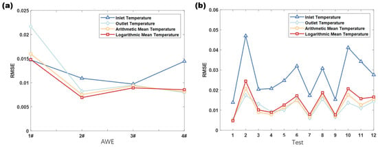
Figure 1.
(a) Electrolytic voltage fitting error variation for different models using different average temperature methods; (b) electrolytic voltage fitting error variation for the same model using different average temperature methods.
3.2. Thermal Euilibrium Field Model
The thermal equilibrium field is the key factor for the stability of the entire model, as the average temperature value of the electrolyzer body is the fundamental independent variable for all state parameters of the electrolyzer body, affecting the characteristics of various physical quantities. Therefore, we need to describe the thermal equilibrium field model of the electrolyzer device based on literature and engineering practices.
3.2.1. Thermal Equilibrium Field Empirical Formula
Equation (5) is the thermal power balance equation for a single alkaline electrolyzer proposed by Ulleberg [10], which mainly involves the following four parts: heat generation, cooling, loss, and net heat power (2) (Figure 2).
where is the total heat capacity of the electrolyzer body (unit: J/K), represents the rate of change of the average temperature of the electrolyzer body over time (unit: K/s), is the heat generation power, is the heat loss power of the electrolyzer body, and is the cooling power.
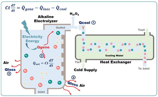
Figure 2.
Schematic diagram of AWE thermal equilibrium.
- a.
- Heat generation power
Concept Definition: The heat generation power of the electrolyzer body mainly refers to the power used for self-heating when the electrolytic voltage exceeds the thermoneutral voltage.
The heat generation power can raise the temperature of the electrolyzer body, eventually reaching suitable working conditions and lowering the cell voltage, thereby improving the overall electrolytic performance. It is specifically expressed as shown in Equation (6) [10].
where is the cell voltage of the electrolyzer body (unit: V), is the thermoneutral voltage of the cell (unit: V), is the number of cells in the electrolyzer body, and represents the electrolytic current (unit: A).
- b.
- Heat loss power
Concept Definition: The heat loss power of the electrolyzer body () refers to the power exchanged with the external environment through the interfaces of the electrolyzer body, which is not insulated.
Heat from of the electrolyzer body mainly occurs through heat convection and heat radiation through air. Since these two heat exchange methods are related to the average temperature () of the electrolyzer body and the ambient temperature (), a unified total thermal resistance exchange coefficient can be used to represent the capability of the electrolyzer body to exchange heat with the external environment, as shown in Equation (7) [10].
where is the total thermal resistance coefficient of the electrolyzer body (unit: W/K) and represents the ambient temperature (unit: °C or K).
- c.
- Cooling power
Concept Definition: The cooling power of the electrolyzer body refers to the power exchanged between the electrolyzer body and the cooler.
In practical engineering, an alkaline electrolyzer achieves heat exchange with the cooling water through the circulation of the alkaline solution outside the electrolyzer body, ultimately achieving the cooling of the electrolyzer body. Therefore, the actual cooling power of the electrolyzer body mainly includes the power generated by the heat exchange between the cooling water and the alkaline solution and the power of heat loss along the circulation path of the alkaline solution. The former has a larger value at high temperatures, while the latter is smaller and always present. For convenience, the cooling power of the electrolyzer is regarded as the cooling water power generated by the inlet and outlet alkaline solution of the electrolyzer body.
Equation (8) was mainly derived from the empirical formula proposed by Ulleberg [10] and further improved. The cooling supply method was improved from the original current-based supply to maximum rated current-based supply, and a cooling amount adjustment coefficient was set to adjust the dynamic supply of cooling. This improvement achieves the purpose of independently controlling the cooling amount of the electrolyzer body, making the cooling independent of the input current of the electrolyzer body and based on the control mode and method of the adjustment coefficient, which is closer to the actual engineering cooling supply mode and can facilitate subsequent research on cooling control strategies.
where represents the heat capacity of the cooling water (unit: W/K); and represent the outlet and inlet temperatures of the cooling water entering the cooler, respectively; LMTD (Log Mean Temperature Difference; unit: °C) represents the logarithmic mean temperature difference between the electrolyzer body and the external cooler; T represents the average temperature of the electrolyzer body; and are heat exchange coefficients of the cooler (units: W/K, W·K−1·A−1); represents the rated current value of the electrolyzer body (unit: A); and α represents the cooling adjustment coefficient, ranging from 0–1, which is dimensionless and related to the temperature control strategy of the electrolyzer body.
In Equation (11), represents the density of water, which is taken as a constant value of 1000 (unit: kg/m3); represents the cooling flow rate (unit: m3/h); represents the specific heat capacity of water, which is taken as a constant value of 75 (unit: J·mol−1·K−1); and represents the molar mass of water, which is taken as a constant value of 18.016 (unit: g/mol).
Equation (10) is obtained by solving Equations (8) and (9) simultaneously, indicating that the outlet temperature of the cooling water can be determined based on the current average temperature of the electrolyzer body, the inlet temperature of the cooling water, and the current cooling adjustment coefficient. Substituting it into Equation (8) and solving Equation (11) then yields the current cooling power of the electrolyzer device.
Equation (11) improves the expression of the heat capacity of the cooling water by setting the alkaline solution flow rate equal to the cooling water flow rate. This improvement enhances the control of the cooling amount, making the control of the alkaline solution flow rate equivalent to the control of the cooling flow rate, consistent with the characteristic of the alkaline solution circulation volume significantly affecting the cooling amount in practical engineering. This improvement also provides greater optimization flexibility for dynamic model control adjustments.
- d.
- Net heat generation power
Net heat generation power represents the residual power value after subtracting the relevant losses and cooling power from the heat generation power. The expression for net heat generation power is shown in Equation (12). It characterizes the temperature state change relationship of the electrolyzer device. The sign of this value indicates whether the electrolyzer is in a heating or cooling process. The thermal resistance coefficient () of the electrolyzer body can represent the heating capacity of the electrolyzer. A larger value indicates a slower rate of change in the average temperature of the electrolyzer body under the same net power input, which is not conducive to rapid loading and a temperature rise of the electrolyzer.
3.2.2. Thermal Equilibrium Field Fitting Parameters
To establish the thermal equilibrium field model, it is necessary to sequentially solve for , , and cooling fitting parameters and . Model construction is then based on empirical formulas. During the electrolyzer testing process, gradient variable load testing was arranged. This process can test the balanced state of the electrolyzer at different power load points, thereby calculating the state information of each power balance point.
According to Equation (5), when the electrolyzer reaches a balance point, its output power achieves dynamic equilibrium, the net heat generation power is zero, and the temperature remains dynamically stable. By using these temperature balance points, the average value of for the electrolyzer can be calculated. Additionally, by analyzing and calculating the dynamic balance time between the balance points of continuous test conditions, the average heat capacity () of the electrolyzer can be deduced. Subsequently, using the obtained coefficients in Equation (10) to calculate the cooling power at other points, then using the empirical formula for cooling power, the values of and can be calculated and fit. It is important to note that the engineering test data may cause deviations in the fitting parameters, requiring parameter correction based on the original data. The final parameters are shown in Table 3.

Table 3.
Thermal equilibrium model-fit parameters.
3.2.3. Cooling Adjustment Coefficient Strategy
Accelerating the heating process is necessary for AWEs in industry. When the discrepancy between the temperature of the electrolyzer and the prescribed temperature is considerable, specifically the juncture at which is considerable, the cooling quantity coefficient should be minimal. Furthermore, the electrolyzer is essential for maintaining the heat balance during normal operation. When the electrolyzer temperature is close to the set temperature, specifically when is minimal, the cooling capacity factor must be sufficiently large to counteract the operating heat production of the electrolyzer. This feature bears resemblance to the tanh function, which is utilized in the modeling of neural networks. This function exhibits a curve that is capable of achieving minor variations in the initial portion of the control range and significant variations in the subsequent sections (Figure 3a). Accordingly, the cooling capacity coefficient () is defined in relation to the tanh function (Figure 3b):
where is the difference between the current temperature and the set temperature, taken as a negative value. According to the characteristics of the hyperbolic tangent function graph, the variable threshold range is generally ±5. Here, the range of −5 °C to 0 °C is used; thus, when changing the range of , appropriate mathematical transformations are required.
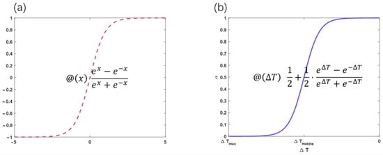
Figure 3.
(a) Tanh function; (b) formula.
Since the temperature control requirements may differ during the startup and shutdown processes, the set temperatures used in different processes may also vary. Below, we present the design of a cooling control strategy with the specific algorithm process.
- a.
- Startup Process Control Strategy
When the electrolyzer is in the startup heating process, the control strategy determines whether the current average temperature () of the electrolyzer body is greater than or equal to the set cooling water start temperature (). If so, the model turns on the cooling water, and the opening degree of the cooling water is determined by the cooling adjustment coefficient (α). The temperature difference () is the difference between the current temperature () and the maximum stable working temperature () of the electrolyzer body, and the value of can be obtained according to Equations (13) and (14). Otherwise, the cooling water is not turned on.
- b.
- Shutdown Process Control Strategy
Similarly, when the electrolyzer is in the shutdown process, the control strategy determines whether the current average temperature () of the electrolyzer body is greater than or equal to the set cooling water shutdown temperature (). If so, the model turns on the cooling water, and the opening degree of the cooling water is determined by the cooling adjustment coefficient (α). The temperature difference () is the difference between the current temperature () and the minimum safe set temperature () of the electrolyzer body, and the value of can be obtained according to Equations (13) and (14). Otherwise, the cooling water is not turned on.
By using this method, the cooling amount can be controlled more effectively, ensuring the electrolyzer operates within safe temperature ranges during both startup and shutdown processes.
3.3. Polarization Function Model
Typically, under constant temperature conditions in the electrolyzer body, the curve of the relationship between cell voltage and cell current is the polarization curve of the electrolyzer. Since the electrode area of the cell in the same electrolyzer body is constant, the curve of the relationship between cell voltage and current can also be described as the curve of the relationship between cell voltage and current density. This standardizes the evaluation of the current end, making it easier for people to intuitively observe the electrolytic performance of different types of electrolyzers through the curve. Therefore, the current values for the electrolyzer body are subsequently converted into current density for description.
- a.
- Reversible voltage
The relationship between components of the electrolytic voltage and the calculation of thermal reactions is described according to the previously discussed basic principles of electrolyzers. Generally, electrolyzer systems operate under constant voltage conditions. Therefore, the curve of the polarization relationship can be fit and solved using the following semi-empirical formula:
where is the reversible voltage, which is a variable related to the electrolyzer’s body temperature () and hydrogen production pressure ; are the fitting parameters; is the current value; and is the electrode area.
Using test data to calculate the average temperature () of the electrolyzer body, given the temperature, current, test voltage, and electrode area, the corresponding value can be obtained. With these conditions satisfied, the fitting parameters can be solved using nonlinear fitting algorithms such as the Levenberg–Marquardt algorithm. As shown in Figure 4, the average fitting accuracy is above 95%, and the fitting parameters of the semi-empirical formula are listed in Table 4.
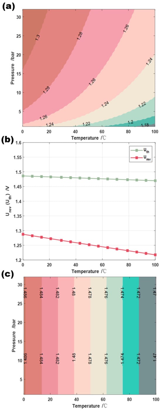
Figure 4.
Relationships between (a) and T and p; (b) and and T; and (c) and T and p.

Table 4.
Polarization function fitting results.
- b.
- Polarization function fit
Using test data to calculate the average temperature of the electrolyzer body, given the temperature, current, test voltage, and electrode area, the corresponding value can be obtained using the algorithm (see Supporting Materials). With these conditions satisfied, the fitting parameters can be solved using nonlinear fitting algorithms such as the Levenberg–Marquardt algorithm. As shown in Figure 5, the average fitting accuracy is above 95%, and the fitting parameters of the semi-empirical formula are listed in Table 4. The semi-empirical model is typically developed in conjunction with a single electrolyzer, with an estimated polarization curve error of approximately 2% [22,23]. In light of the disparate performance of the four electrolyzers and the power characteristics employed in this study for model construction, an error of 5% for a single electrolyzer is deemed acceptable, given the model’s universal applicability.
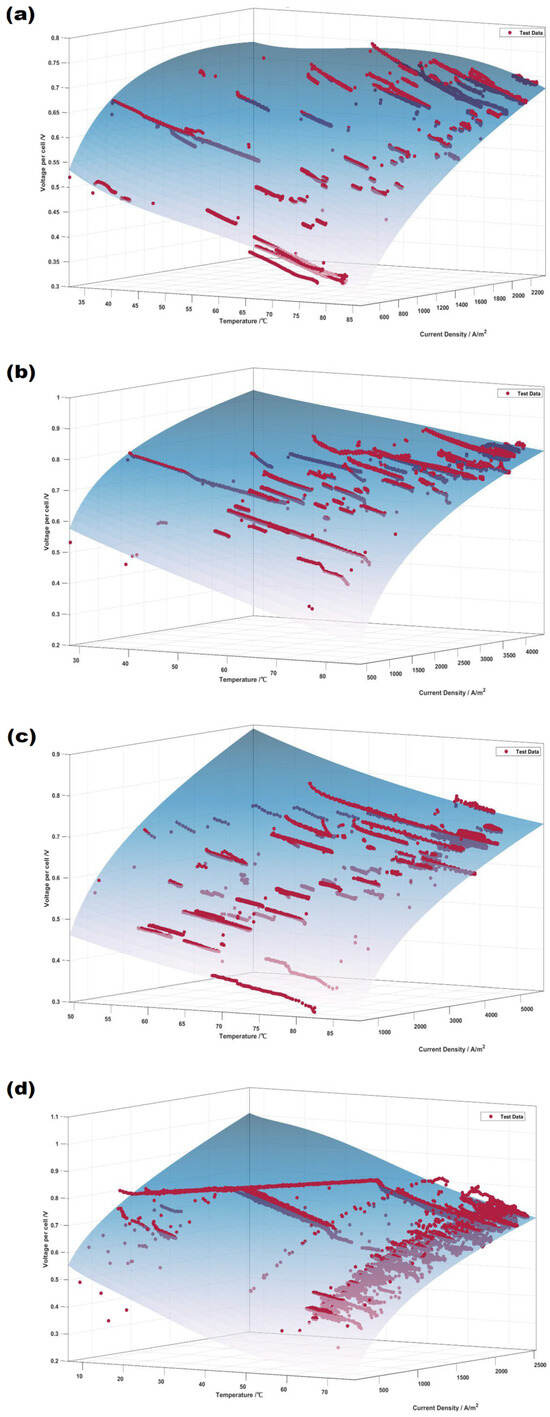
Figure 5.
Polarization function fitting results of electrolyzers 1–4 (a–d, respectively).
- a.
- Analysis of Polarization Characteristics
Without additional strategic constraints, the relationship between the state variables of the polarization curve-fitting model can be solved, resulting in the polarization characteristic curves between the cell voltage, current density, and average temperature of the electrolyzer body, as shown in Figure 6. Overall, different electrolyzer devices exhibit different characteristics. Among them, the internal materials and structures of these four electrolyzers differ, resulting in different trends in cell voltage changes on the polarization curve. Additionally, the rate at which cell voltage changes with the average temperature of the electrolyzer body reflects the startup performance of the electrolyzer device and the difficulty of high-load loading at low temperatures.
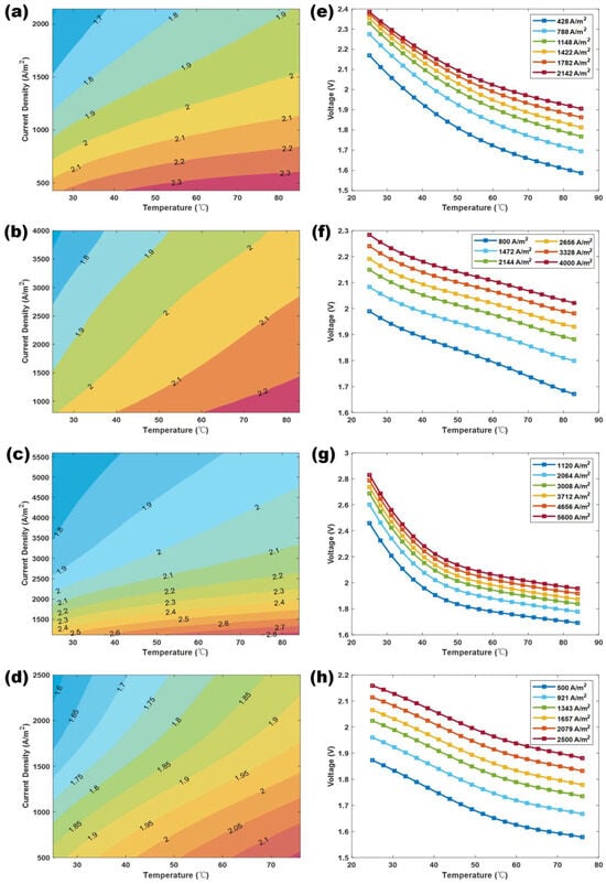
Figure 6.
(a–d) Relationships between voltage and temperature and current density of electrolyzers 1#–4#. (e–h) Relationships between voltage and average temperature of electrolyzers 1#–4#.
From the polarization characteristics of these four types of electrolyzer devices, it can be seen that the cell voltage of electrolyzer 3# is too high under low-temperature conditions, generally exceeding the protection voltage of 2.2 V set for the cell in engineering. Therefore, for this model, the input power during low-temperature loading cannot be too high, i.e., the startup current cannot be too large, as it easily breaks the protection voltage limit of the electrolyzer body, causing the device to shut down protectively. On the other hand, the cell voltage of electrolyzer 4# is generally below the protection value in the low-temperature region, indicating that this device can start with a higher input power in low-temperature environments, allowing the device to quickly reach a working balance state under the set input current conditions. This polarization characteristic directly shows the power response speed of different electrolyzer devices, reflecting their hydrogen production efficiency.
Moreover, the density of the cell voltage change curves presented in Figure 6a–d on the left also represents the overall performance change of the electrolyzer device under different temperature and current density conditions. Dense regions indicate a large range of power loading changes in that temperature range, implying a significant performance improvement potential in that area and vice-versa. This is due to differences in the use years and internal component materials between electrolyzers 1# and 4#. Electrolyzers 1# and 4# have similar internal components, but electrolyzer 4# has been in use for a longer time. Electrolyzer 3# has the latest internal materials, while electrolyzer 2# is a transitional design between 1#, 4#, and 3#. It can be seen that the operating duration and design current density significantly affect the performance of the electrolyzer body. The longer the operating duration, the more stable the performance, with better performance in the low-temperature region. The design current density affects the overall performance of the device, with high-current density designs having significant room for improvement.
3.4. Faraday Efficiency Model
Faradaic efficiency represents the electrolytic efficiency of the electrolyzer, determining the hydrogen production rate at each state point of the electrolyzer. Equation (16) [10] reveals that the hydrogen production rate is influenced only by Faradaic efficiency () and current (). Thus, once the Faradaic efficiency curve of the electrolyzer is determined, its hydrogen production capability can be calculated using the following formula:
where represents the hydrogen production rate (unit: Nm3/h); is the Faradaic efficiency; is the number of cells in the electrolyzer; is the applied current; and and represent the number of moles of electrons transferred per mole of reaction and the Faraday constant, respectively.
At the beginning of this century, researchers proposed four-parameter and five-parameter empirical fitting models for Faradaic efficiency in alkaline electrolyzers [10,15]. This paper mainly uses the five-parameter empirical formula (see Equation (17)) [15] to fit the four electrolyzers. During data analysis, it was found that the hydrogen production rate monitoring error in commercial alkaline water electrolysis systems is relatively large, leading to some inaccuracies in fitting precision. This paper focuses on introducing the fitting method and providing the necessary equipment state variables to meet the realistic simulation needs of the equipment. Subsequent precise data collection through related tests can reduce the model’s output error.
where represents Faradaic efficiency (unit: %), represents the temperature of the electrolyzer body, is the applied current, is the effective reaction area of the electrolyzer body (i.e., the electrode area, unit: m2), and are the fitting parameters (Table 5).

Table 5.
Faraday efficiency fitting results.
3.5. Gas Purity Model
The gas purity model mainly refers to the empirical model of hydrogen in oxygen (HTO). This is because the electrolysis process involves a reverse reaction, and under high-pressure conditions, some dissolved gases in the solution at the cathode and anode reaction zones are released, resulting in a small mixture of hydrogen and oxygen gases, causing gas impurity. Among these, the presence of hydrogen in oxygen is the most evident and is significantly affected by temperature, pressure, and applied current. Therefore, engineering studies generally use the percentage of hydrogen in oxygen (HTO) as the main reference to reflect the hydrogen production purity of the equipment. This indicator also partially represents the safety of the hydrogen production equipment. For hydrogen in an oxygen mixture, the Lower Flammability Limit (LFL) and Upper Flammability Limit (UFL) are 4% and 94%, respectively. When the gas purity is too low, potential safety hazards may be present in the hydrogen production equipment, possibly due to structural damage within the electrolyzer body, leading to severe hydrogen–oxygen crossover and potentially resulting in flames or an explosion. Therefore, this paper mainly uses the related HTO empirical formula introduced in the literature [15] (as shown in Equation (18)) to build the gas purity model for the four types of electrolyzer.
Since in the operational settings of commercial electrolyzers, the hydrogen production pressure is generally set as constant, the actual model does not include pressure-related influencing factors, instead considering only the effects of the average temperature and the electrolysis current.
where represents the percentage of hydrogen in oxygen (unit: %), T represents the temperature of the electrolyzer body; I is the applied current, A is the effective reaction area of the electrolyzer body (i.e., the electrode area; unit: m2), and are the fitting parameters (Table 6). The model calculations yielded maximum values of HTO below 0.5% for all four electrolyzers, indicating that the electrolyzers were operating within the safe range.

Table 6.
HTO model fitting parameters.
3.6. Overall Simulation Model
By combining and assembling the above component models, this paper establishes an overall dynamic simulation model in MATLAB R2022b and Simulink (see Figure 7). This model can be used for standalone operation simulation and subsequent module encapsulation. Notably, the MATLAB class model can conveniently construct an electrolytic hydrogen production cluster model, providing an excellent foundational tool for future cluster simulations. Subsequent research will also use this encapsulated module for system strategy simulations.
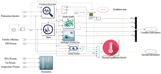
Figure 7.
Schematic diagram of the proposed overall simulation method.
4. Model Validation and Simulation Results
To validate the accuracy of the electrolyzer model, this section introduces the simulation results of the electrolyzer’s startup and shutdown processes and statistics of the changes in related model parameters to analyze the accuracy of the model expression and the effectiveness of the operation strategy. Therefore, the simulation work mainly involves loading and unloading the rated current for the four electrolyzers, with the simulation duration set to 6 h. The changes in relevant model parameters are output, and the simulation data are then organized and analyzed.
4.1. Analysis of Startup and Shutdown Current Results
As shown in Figure 8, for full-load input (constant current control, i.e., rated current input conditions), an electrolyzer model with an overload monitoring module self-adjusts its current based on its state until it meets the input current requirements. Additionally, the changes in the loading current reveal significant differences in the self-regulation capabilities of the four electrolyzers.
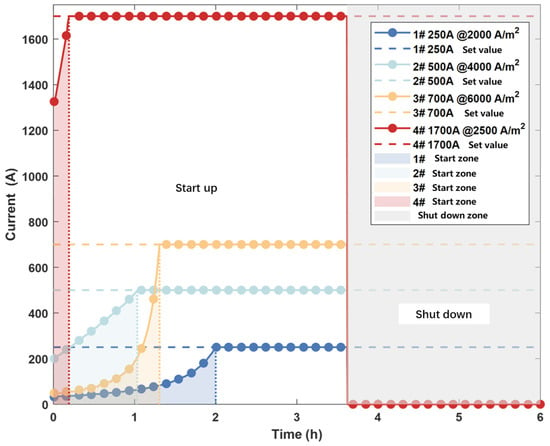
Figure 8.
Current change of startup and shutdown conditions.
Among the tested electrolyzers, electrolyzer 4# has a very fast current loading speed, reaching full-load operation in a short time, thereby enhancing the overall heating speed of the electrolyzer. In contrast, electrolyzer 1# takes 2 h to reach full load, which is the slowest among the four electrolyzers, mainly due to the structural differences and overall thermal efficiency of the device.
4.2. Changes in Other Major Parameters during Startup and Shutdown
Figure 9 describes the changes in cell voltage, maximum loadable power, overall hydrogen production efficiency, and specific energy consumption for hydrogen production under startup and shutdown conditions.
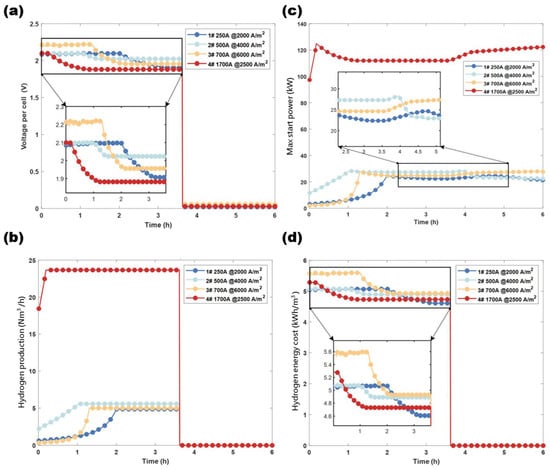
Figure 9.
(a) Voltage change during simulation. (b) Max start power during startup. (c) Hydrogen production rate during simulation. (d) Hydrogen production energy cost during simulation.
Figure 9c shows the maximum loadable power under overload constraints, where the temperature differences in the electrolyzer body cause variations in cell voltage. At low temperatures, cell voltage increases rapidly with the applied current, while at high temperatures, the change is smaller. Figure 9a shows that under the constraints of the overload monitoring module, the cell voltages of the electrolyzers are generally controlled below 2.1 V, ensuring the safety and reliability of the electrolyzers under startup load impacts. The stable full-load voltages are also controlled between 1.85 V and 2.05 V. The trend in Figure 9b is generally consistent with the changes in loading current, verifying that the hydrogen production rate is approximately directly proportional to the current in the model. Figure 9d expresses the changes in the electrolyzer hydrogen production efficiency, a critical parameter for evaluating electrolyzer performance. The figure shows that electrolyzer 1# has the lowest steady-state DC energy consumption of around 4.6 kWh/Nm3, indicating good electrolytic efficiency at high temperatures, which is consistent with the conclusions of other research studies [24,25]. In contrast, electrolyzer 3# has an overall DC energy consumption above 4.95 kWh/Nm3, with low-temperature peak consumption reaching 5.6 kWh/Nm3, indicating significant room for improvement in the overall electrolytic efficiency of high-current density electrolyzers.
4.3. Changes in Initial Temperature
Temperature simulation of the electrolyzer is a critical aspect of the overall model expression, with the thermal equilibrium point of the electrolyzer system representing the balance state. Under startup conditions, the temperature-loading conditions of each electrolyzer vary (Figure 10).
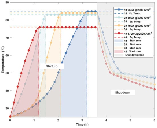
Figure 10.
Temperature changes of four electrolyzers during simulation.
Electrolyzer 1# shows the slowest temperature-loading speed but has the highest equilibrium temperature. In contrast, electrolyzer 4# has the fastest overall temperature-loading speed but the lowest equilibrium temperature. This is because the thermal equilibrium of commercial electrolyzers is related to the cooling capacity and efficiency of external cooling facilities. Generally, low-load electrolyzers have low overall heat production, allowing cooling facilities to quickly meet cooling supply demands, achieving overall thermal equilibrium. However, high-load electrolyzers generate large amounts of transient heat, requiring a high thermal exchange capacity from cooling facilities. To ensure system thermal equilibrium, a lower working temperature equilibrium point is set, providing sufficient balance time and stability margin, protecting the overall operation system of the electrolyzer. Figure 10 also shows that the cooling modes differ in the shutdown region, which is related to the choice strategy of the cooling coefficient in the temperature cooling model. The shutdown cooling mode in system simulation is set as follows: if the temperature exceeds 50 °C, the model fully opens the cooling water for rapid cooling; below 50 °C, the model shuts off the cooling water, allowing only natural cooling. This strategy ensures that high-temperature electrolyzers quickly cool to safe temperatures during shutdown, ensuring the safety of the overall electrolyzer shutdown process, aligning with practical operational management modes, and enhancing the simulation’s practical operational expression capabilities.
4.4. Changes in Physical Quantities of the Thermal Equilibrium Field
Figure 11 describes the relevant parameters of the thermal equilibrium field of the simulation model.
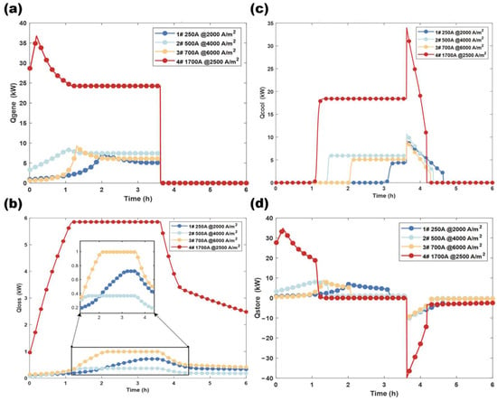
Figure 11.
Separate power during simulation: (a) heat-generating power; (b) heat-loss power; (c) cooling power; (d) net heating power.
As shown in Figure 11, the main thermal power variables of the electrolyzer are heat generation power, cooling power, and net heat generation power, with the system’s heat-loss power accounting for a small proportion. The peak heat-loss power accounts for 1–5% of the rated power. The changes in net heat generation power also reflect significant differences in the temperature-loading capabilities of different electrolyzers, further verifying the changes in loading current of the electrolyzer, indicating that the inherent properties of the electrolyzer significantly impact its thermal field, and affecting overall loading capabilities and electrolytic efficiency.
Overall, the startup and shutdown simulation results of the electrolyzer are consistent with the actual test expressions, indicating that the semi-empirical mathematical model and operational control strategy used in this study can effectively express actual commercial electrolyzer requirements. This model can be used to study subsequent control strategies for the adaptation of electrolytic hydrogen production systems to renewable energy power fluctuations.
5. Conclusions
This paper systematically studied and constructs a dynamic simulation model for alkaline electrolyzers. It introduced the power characteristics of wind power generation and a wind power estimation model, providing a calculation method for the power fluctuation curve of wind farms for subsequent simulation models. Experimental testing and characteristic analysis of the electrolyzer device are emphasized, providing a detailed introduction to the structure of the electrolyzer device and the experimental test conditions. Finally, the analysis reveals that the alkaline electrolyzer device has characteristics such as a long startup time, rapid dynamic response, and poor dynamic stability, providing theoretical basis and data support for the subsequent establishment of an electrolyzer device model and for the development of related strategies.
By analyzing and combining various component models in detail, a comprehensive dynamic simulation model in MATLAB and Simulink was established, which was used for standalone operation simulation and subsequent module encapsulation. This model not only facilitates the construction of an electrolytic hydrogen production cluster model, providing a foundational tool for cluster simulation, but can also be used for the study of system strategy simulations.
During the simulation process, rated current loading and unloading operations were performed on four types of electrolyzer, with the simulation duration set to 6 h. The changes in relevant model parameters were output, and the simulation data were organized and analyzed. The simulation results show significant differences in the startup and operation processes of different electrolyzers. In the temperature simulation section, the thermal equilibrium points of the electrolyzers were analyzed, and comparisons of temperature-loading conditions revealed significant differences in the temperature equilibrium points and cooling modes of different electrolyzers. These differences are primarily determined by the structural design and cooling system efficiency of the electrolyzers. The simulation results indicate that high-load electrolyzers perform well in low-temperature regions, but high-current density electrolyzers still have significant room for improvement in overall electrolytic efficiency. These findings provide a theoretical basis for the optimization of the design and operation of electrolyzers in practical engineering.
Simulation analysis of the changes in relevant parameters of the thermal equilibrium field further validates the temperature-loading capability and thermodynamic characteristics of different electrolyzers. The results show that the inherent properties of the electrolyzers have a significant impact on their thermal fields, thereby affecting overall loading capability and electrolytic efficiency. Overall, the startup and shutdown simulation results of the electrolyzers are consistent with actual test results, indicating that the semi-empirical mathematical model and operation control strategy used in this study can effectively express the working characteristics of commercial electrolyzers.
In conclusion, the dynamic simulation model of the electrolyzers constructed in this paper and its simulation results not only provide a reliable tool and data support for the subsequent study of control strategies for the adaptation of a electrolytic hydrogen production system to renewable energy power fluctuations but also lay a solid foundation for further optimization of the design and operation strategies of electrolyzers.
Supplementary Materials
The following supporting information can be downloaded at: https://www.mdpi.com/article/10.3390/en17194915/s1, Figure S1: Schematic diagram of AWE schematic pipeline instruments.
Author Contributions
J.Y.: Writing—original draft, Software; J.Z.: Methodology, Supervision; M.L.: Writing—review & editing, Supervision, Funding acquisition; J.S.: Writing—review & editing, Funding acquisition. Z.S.: Software, Data curation, Visualization. All authors have read and agreed to the published version of the manuscript.
Funding
This research was funded by [State Grid Zhejiang Electric Power Company Taizhou Power Supply Company] grant number [5211TZ220003]. The APC was funded by [Tongji University].
Data Availability Statement
The original contributions presented in the study are included in the article, further inquiries can be directed to the corresponding author.
Conflicts of Interest
Authors Jian Yang and Jie Sun were employed by the company “State Grid Zhejiang Electric Power Company Taizhou Power Supply Company”, Author Min Liu was employed by the company State Grid Zhejiang Electric Power Co., Ltd. The remaining authors declare that the research was conducted in the absence of any commercial or financial relationships that could be construed as a potential conflict of interest.
References
- Holladay, J.D.; Hu, J.; King, D.L.; Wang, Y. An overview of hydrogen production technologies. Catal. Today 2009, 139, 244–260. [Google Scholar] [CrossRef]
- Zou, X.; Zhang, Y. Noble metal-free hydrogen evolution catalysts for water splitting. Chem. Soc. Rev. 2015, 44, 5148–5180. [Google Scholar] [CrossRef] [PubMed]
- Amores, E.; Rodríguez, J.; Carreras, C. Influence of operation parameters in the modeling of alkaline water electrolyzers for hydrogen production. Int. J. Hydrogen Energy 2014, 39, 13063–13078. [Google Scholar] [CrossRef]
- Zeng, K.; Zhang, D. Recent progress in alkaline water electrolysis for hydrogen production and applications. Prog. Energy Combust. Sci. 2010, 36, 307–326. [Google Scholar] [CrossRef]
- Millet, P.; Grigoriev, S. Water electrolysis technologies. In Renewable Hydrogen Technologies: Production, Purification, Storage, Applications and Safety; Elsevier: Amsterdam, The Netherlands, 2013; p. 19. [Google Scholar] [CrossRef]
- Wang, L.; Chen, M.; Küngas, R.; Lin, T.-E.; Diethelm, S.; Maréchal, F.; Van Herle, J. Power-to-fuels via solid-oxide electrolyzer: Operating window and techno-economics. Renew. Sustain. Energy Rev. 2019, 110, 174–187. [Google Scholar] [CrossRef]
- Doenitz, W.; Schmidberger, R. Concepts and design for scaling up high temperature water vapour electrolysis. Int. J. Hydrogen Energy 1982, 7, 321–330. [Google Scholar] [CrossRef]
- Salzano, F.J.; Skaperdas, G.; Mezzina, A. Water vapor electrolysis at high temperature: Systems considerations and benefits. Int. J. Hydrogen Energy 1985, 10, 801–809. [Google Scholar] [CrossRef]
- Hug, W.; Bussmann, H.; Brinner, A. Intermittent operation and operation modeling of an alkaline electrolyzer. Int. J. Hydrogen Energy 1993, 18, 973–977. [Google Scholar] [CrossRef]
- Ulleberg, Ø. Modeling of advanced alkaline electrolyzers: A system simulation approach. Int. J. Hydrogen Energy 2003, 28, 21–33. [Google Scholar] [CrossRef]
- Artuso, P.; Gammon, R.; Orecchini, F.; Watson, S.J. Alkaline electrolysers: Model and real data analysis. Int. J. Hydrogen Energy 2011, 36, 7956–7962. [Google Scholar] [CrossRef]
- Ursúa, A.; Sanchis, P. Static–dynamic modelling of the electrical behaviour of a commercial advanced alkaline water electrolyser. Int. J. Hydrogen Energy 2012, 37, 18598–18614. [Google Scholar] [CrossRef]
- Haug, P.; Kreitz, B.; Koj, M.; Turek, T. Process modelling of an alkaline water electrolyzer. Int. J. Hydrogen Energy 2017, 42, 15689–15707. [Google Scholar] [CrossRef]
- Sánchez, M.; Amores, E.; Rodríguez, L.; Clemente-Jul, C. Semi-empirical model and experimental validation for the performance evaluation of a 15 kW alkaline water electrolyzer. Int. J. Hydrogen Energy 2018, 43, 20332–20345. [Google Scholar] [CrossRef]
- Sánchez, M.; Amores, E.; Abad, D.; Rodríguez, L.; Clemente-Jul, C. Aspen Plus model of an alkaline electrolysis system for hydrogen production. Int. J. Hydrogen Energy 2020, 45, 3916–3929. [Google Scholar] [CrossRef]
- Henao, C.; Agbossou, K.; Hammoudi, M.; Dubé, Y.; Cardenas, A. Simulation tool based on a physics model and an electrical analogy for an alkaline electrolyser. J. Power Sources 2014, 250, 58–67. [Google Scholar] [CrossRef]
- Milewski, J.; Guandalini, G.; Campanari, S. Modeling an alkaline electrolysis cell through reduced-order and loss-estimate approaches. J. Power Sources 2014, 269, 203–211. [Google Scholar] [CrossRef]
- Diéguez, P.; Ursúa, A.; Sanchis, P.; Sopena, C.; Guelbenzu, E.; Gandía, L. Thermal performance of a commercial alkaline water electrolyzer: Experimental study and mathematical modeling. Int. J. Hydrogen Energy 2008, 33, 7338–7354. [Google Scholar] [CrossRef]
- Li, C.; Baek, J.B. The promise of hydrogen production from alkaline anion exchange membrane electrolyzers. Nano Energy 2021, 87, 106162. [Google Scholar] [CrossRef]
- Lee, J.; Alam, A.; Ju, H. Multidimensional and transient modeling of an alkaline water electrolysis cell. Int. J. Hydrogen Energy 2021, 46, 13678–13690. [Google Scholar] [CrossRef]
- Busch, P.; Lahti, P.; Werner, R.F. Colloquium: Quantum root-mean-square error and measurement uncertainty relations. Rev. Mod. Phys. 2014, 86, 1261–1281. [Google Scholar] [CrossRef]
- Shen, X.; Zhang, X.; Lie, T.T.; Li, G. Mathematical modeling and simulation for external electrothermal characteristics of an alkaline water electrolyzer. Int. J. Energy Res. 2018, 42, 3899–3914. [Google Scholar] [CrossRef]
- Ren, Z.; Wang, J.; Yu, Z.; Zhang, C.; Gao, S.; Wang, P. Experimental studies and modeling of a 250-kW alkaline water electrolyzer for hydrogen production. J. Power Sources 2022, 544, 231886. [Google Scholar] [CrossRef]
- Li, Y.; Zhang, T.; Ma, J.; Deng, X.; Gu, J.; Yang, F.; Ouyang, M. Study the effect of lye flow rate, temperature, system pressure and different current density on energy consumption in catalyst test and 500W commercial alkaline water electrolysis. Mater. Today Phys. 2022, 22, 100606. [Google Scholar] [CrossRef]
- Jang, D.; Choi, W.; Cho, H.-S.; Cho, W.C.; Kim, C.H.; Kang, S. Numerical modeling and analysis of the temperature effect on the performance of an alkaline water electrolysis system. J. Power Sources 2021, 506, 230106. [Google Scholar] [CrossRef]
Disclaimer/Publisher’s Note: The statements, opinions and data contained in all publications are solely those of the individual author(s) and contributor(s) and not of MDPI and/or the editor(s). MDPI and/or the editor(s) disclaim responsibility for any injury to people or property resulting from any ideas, methods, instructions or products referred to in the content. |
© 2024 by the authors. Licensee MDPI, Basel, Switzerland. This article is an open access article distributed under the terms and conditions of the Creative Commons Attribution (CC BY) license (https://creativecommons.org/licenses/by/4.0/).