Article

Adaptive Current Angle Compensation Control Based on the Difference in Inductance for the Interior PMSM of Vehicles

1
Heilongjiang University of Industry and Business, Harbin 150001, China
2
Heilongjiang Dewo Technology Development Co., Ltd., Harbin 150001, China
3
Harbin Institute of Technology, Harbin 150001, China
*
Author to whom correspondence should be addressed.
Energies 2024, 17(19), 4905; https://doi.org/10.3390/en17194905
Submission received: 24 August 2024 / Revised: 22 September 2024 / Accepted: 24 September 2024 / Published: 30 September 2024
(This article belongs to the Section F3: Power Electronics)

Abstract

:
Achieving good performance in terms of a fast and accurate maximum torque per ampere (MTPA) control method depends on both accurate parameter estimation and a sophisticated control strategy. However, it often requires a complex and long computational process. This paper proposes an efficient control method using the relationship of torque and current angle for maximum torque per ampere control of the interior permanent magnet synchronous motor (IPMSM) for vehicle application. It was found that it is not necessary for the control method to determine the inductance in the d-q axes; the identification of the difference between each axis is enough. Furthermore, this paper presents a simple and effective procedure to estimate the difference in inductance online, where the linear iron loss calculation method is also designed to support the above process. The proposed control method was experimentally validated on a 5 kW prototype by a TMS320F28335 microcontroller and DSPACE synchronized with a personal computer. The results show that the control process has faster and more accurate performance than the conventional method.

1. Introduction

The interior permanent magnet synchronous motor has been widely used in electric vehicles (EVs) in the last decades. The IPMSM has the advantages of a high power density and better efficiency over a wide range of speeds, and thus, it is increasingly gaining attention. In addition to permanent magnet torque, the IPMSM also produces a reluctance torque. It has a cross-magnetization phenomenon due to the interaction between direct and quadratic currents; that is, the direct and quadratic currents share these two kinds of torque [1,2,3].
It is well known that with the development of research on IPMSM control in the past decades, the efforts of scholars have made advances in this technology. To date, various MTPA methods have been presented and verified. The first is regular formula calculation, which is really simple and does not require a lot of calculation, but it was found to be too theoretical, especially in heavy load conditions. For a constant current vector, the MTPA method produces maximum torque by adjusting the vector angle [4]. However, it is difficult to obtain accurate MTPA points in actual operation due to sensitive parameters varying with operating conditions [5]. Therefore, scholars have gradually realized that the parameters change a lot under different working conditions, especially the value of inductance in the d-q axes. To solve this problem, some scholars proposed an online estimate method, which is widely used in order to obtain precise data on inductance parameters [6]. Different authors have proposed different methods to estimate and calculate the inductance in the d-q axes and their variation, with and without taking into account cross-saturation [6]. J. C. Li [7] presented a mathematical model of cross-saturation characteristics in which a second-order function is adopted to estimate inductance. Moreover, another method for inductance estimation in the d-q axes was given in [8] using a magnetic equivalent circuit with flux change and the consideration of cross-saturation. This approach proved to be effective, but the results were less accurate than expected. In addition to dynamic inductance estimation, several MTPA control algorithms have been developed by scholars from different perspectives. In recent years, the high-frequency signal injection method that uses differentiation of torque has become more attractive [9,10,11,12]; the shortcoming is that this method results in extra loss and torque ripple. Hence, an improved method based on actual injection named virtual injection was proposed [13], which injects a high-frequency signal into a vector angle instead of injecting it into the motor to avoid problems. The authors of [14] point out that no matter the form of control employed, the approach should fully consider variations in motor parameters. The algorithm discussed in [15] proposed a parameter estimation method using an iterative gradient, which requires a power microcontroller; furthermore, developing and tuning these estimators is a difficult task. Hajime et al. [16] and Inoue et al. [17] proposed a maximum torque control (MTC) reference frame. The greatest feature of the MTC reference frame is that one of the coordinate axes is aligned with the current vector. Its intention is to achieve constant inductance in the MTC reference frame; however, it is obvious that this kind of frame is difficult to track and requires lots of effort and time. In addition, the disturbance torque observer and equivalent parameter models are widely used in MTPA control by scholars in [18,19]; both models can improve the performance of MTPA control. In summary, the research topic of MTPA control mainly focuses on the following aspects:
(1)
To ensure the stability of the system at the same time of improving transient response, some papers have indeed achieved faster results, but these methods are always accompanied by negative effects.
(2)
The accurate identification of sensitive parameters has attracted more attention, but it is difficult to achieve.
(3)
Simplifying the procedure to make the control process easier to achieve in control chips.
This paper first proposes a method using the relationship between the torque and current angle to construct a control law and then proposes a current angle error compensation method in the current control loop. Taylor expansion is adopted around the theoretical optimal point to simplify the difference calculation between the actual current angle and the optimal current angle so that the program can be easily implemented in a DSP28335 chip. This section is presented in Section 3.1. Second, given that the calculation process requires the real-time difference between direct and quadrature axis inductances, it can be seen from the abovementioned literature that it is difficult to obtain the inductance in d-q axes accurately. To this end, in this paper, we adopt a PI controller to calculate the difference value between direct and quadrature axis inductance, considering the difference between the input power and output power as the input of the PI controller; that is to say, we attribute the change in power difference to the change in inductance difference, and a detailed process is shown in Section 3.2.1. Moreover, it should be noted that both copper loss and iron loss have to be considered in the calculation of the power difference. As is known, it is easy to obtain copper loss but difficult to obtain iron loss. Therefore, a simple linear iron loss estimation method is designed and employed; this procedure is described in Section 3.2.2. In a word, this paper aims to achieve the following advantages:
(1)
The proposed method is supposed to have faster performance than traditional methods.
(2)
It eliminates the need to identify inductance in the d-q axes. There is no need for a complex derivation process, and it can still obtain the optimization results.

2. Model of IPMSM and MPTA Control

The voltage equations of IPMSM in the rotating reference frame are expressed as [19]
u d = R i d + L d d i d d t ω L q i q
u q = R i q + L q d i q d t + ω L d i d + ω φ f
where ud, uq, id, and iq are the voltages and currents in the d-q frames, respectively. Ld, Lq denote inductance in the d-q frame; R, ω, and φf denote stator resistance, electrical angle velocity, and permanent magnet flux linkage, respectively. The electromagnetic torque can be expressed as follows:
T e = 1.5 p [ φ f i q + ( L d L q ) i d i q ]
Thus, an optimal problem arises
min i d , i q f = i d 2 + i q 2 S ubject to   T e 1.5 p [ φ f i q + ( L d ( i d , i q ) L q ( i d , i q ) ) i d i q ] = 0 i d 2 + i q 2 I s 2
where both Ld (id, iq) and Lq (id, iq) vary with id and iq; moreover, φf relates to the temperature. For (4), the Lagrange multiplier is adopted to obtain an approximate solution, and the function is constructed as
F ( i d , i q , λ ) = i d 2 + i q 2 + λ T e 1.5 p [ φ f i q + ( L d ( i d , i q ) L q ( i d , i q ) ) i d i q ]
where λ is the Lagrange multiplier; let the partial derivatives of F with respect to id, iq, and λ equal zero, and the results are finally obtained as (6)
i d + L d ( i d , i q ) L q ( i d , i q ) φ f ( i d 2 i q 2 ) + i d i q φ f i d L d ( i d , i q ) i q L q ( i d , i q ) i q i q L d ( i d , i q ) i d L q ( i d , i q ) i d = 0
It is obvious that there are two parts in (6): the first part denotes the conventional MTPA condition, while the second part is an additional item due to inductance variation in actual operation.
Figure 1 shows the MTPA trajectory and torque contours according to (3) and (6). The dotted green line denotes the MTPA points with different loads, and the red line denotes the simulated MTPA points. This indicates that there is little difference between them at low current conditions. On the contrary, there are significant deviations between the two trajectories at high current regions. Therefore, it can be concluded that the effect of nonlinear inductance has inaccurate results in the conventional MTPA method.

3. Current Vector Angle Compensation Control

3.1. Current Vector Angle Compensation with Variable Gain

According to the analysis above, the change in the parameters cannot be ignored in actual working conditions; otherwise, it is impossible to obtain accurate results. Equation (3) is rewritten with current vector amplitude Is and current vector angle β as follows
T e = 1.5 p [ φ f I s sin β + 0.5 I s 2 L d ( i d , i q ) L q ( i d , i q ) sin 2 β ]
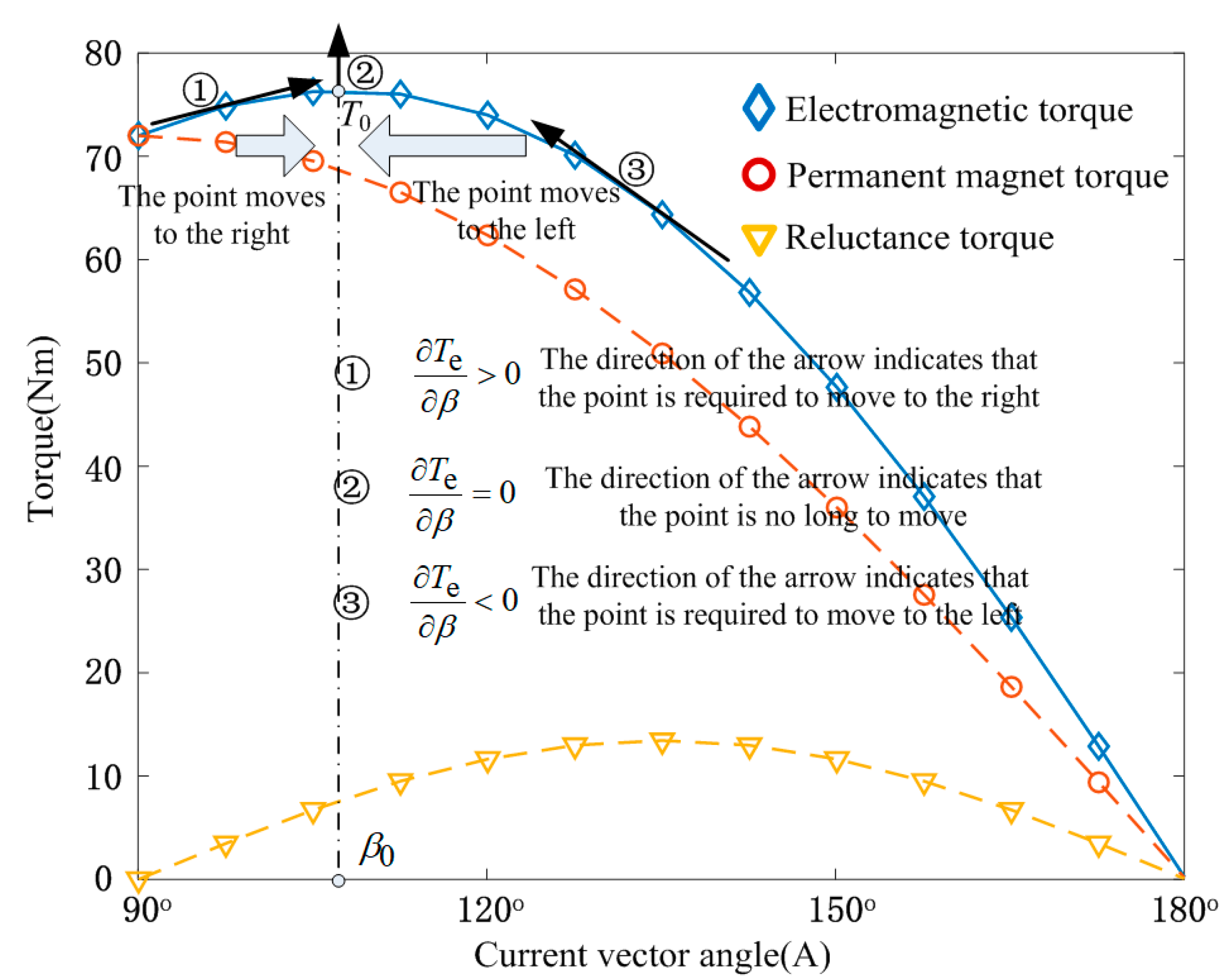
Figure 2 is depicted according to (7).
For the IPMSM, the electromagnetic torque consists of permanent magnet torque and reluctance torque. It can be seen from the electromagnetic torque loci in Figure 2 that there is only one maximum point (β0, T0); that means ∂T/∂β equals zero at (β0, T0). Moreover, ∂T/∂β is greater than zero on the left side of the point (β0, T0), and ∂T/∂β is smaller than zero on the right side of the point (β0, T0). Hence, the relationship formula is constructed from Figure 2:
T e / β > 0 β < β 0 T e / β = 0 β = β 0 T e / β < 0 β > β 0
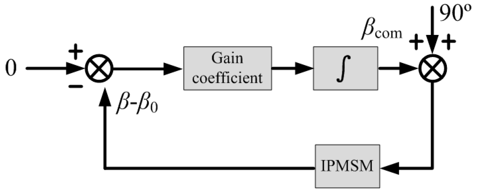
Equation (8) shows the relationship between the actual angle and the optimal angle around the point (β0, T0), where ∂T/∂β denotes the value of the tangential point. We hope that the actual angle draws nearer to the optimal angle, as shown in Figure 2, by means of effective control. As is known, the MTPA point can be reached when ∂T/∂β equals zero; in other words, we also obtain the MTPA point if the actual β equals β0. In view of this, we can build a simple compensation mode for the current angle, as shown in Figure 3.
In Figure 3, we consider ββ0 as the control object to construct an error-driven closed loop. The initial angle is set to 90°; that is to say, id = 0 control is regarded as the initial state. Therefore, it is necessary to obtain the difference between β and β0 in real-time first; the process of control aims to minimize |ββ0|. However, it is difficult to obtain accurate β0 due to β0 varying with the load. Assuming that f (β) equals ∂T/∂β, then f (β) can be represented by using Taylor expansion at point (β0, T0) as follows:
f ( β ) = f ( β 0 ) + n = 1 f n ( β 0 ) ( β β 0 ) n n !
Equation (9) can be rewritten, with high-order terms ignored, as
f ( β ) = f ( β 0 ) + f ( β 0 ) ( β β 0 )
β-β0 can be derived from (10)
β β 0 = f ( β ) f ( β 0 ) f ( β 0 )
where f (β0) equals zero, and f′ (β) is similar to f′ (β0); thus, (12) is derived from (11), (3), and (7)
β β 0 = K a K b 1
where
K a = φ f i d + L d ( i d , i q ) L q ( i d i q ) ( i d 2 i q 2 ) K b = φ f i q 4 L d ( i d , i q ) L q ( i d i q ) i d i q
The error accumulation of dynamic is calculated by (14)
β 0 = K p K a K b 1 d t
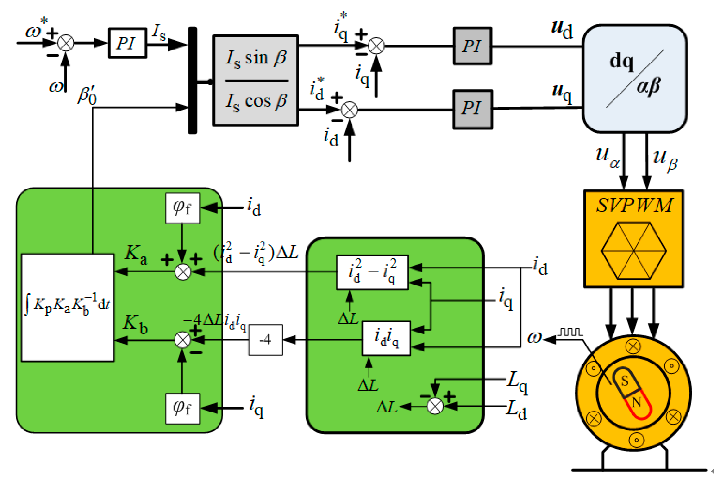
where Kp denotes the integral gain, and β′0 denotes the angle compensation value. The control structure is given in Figure 4. As a matter of fact, the core principle of angle compensation is shown in Figure 3 as an angle optimization procedure. The current vector amplitude Is is assigned to id and iq via vector angle β′0. It should be noted that the precision of β′0 is highly dependent on Ld (id, iq) and Lq (id, iq), as well as permanent magnet flux linkage. However, it is difficult to recognize inductance and flux linkage in dynamic operation; as mentioned above, it is necessary to obtain an accurate value for both parameters in real-time in order to support the method presented in Figure 4.

3.2. Coupling Analysis of DQ Axes Inductance Parameters

It is known that once the coils are connected to three-phase sinusoidal excitation, we can obtain the relationship between the vector angle β and the current in Figure 5. Obviously, the vector angle β impacts the distribution of the d-q axes current.
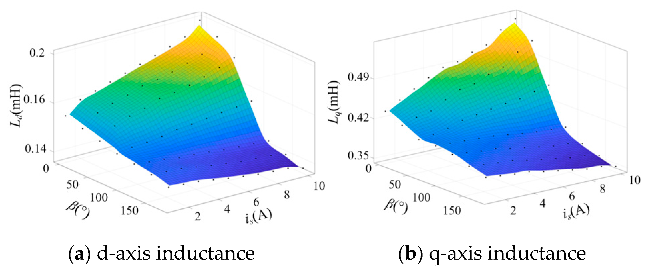
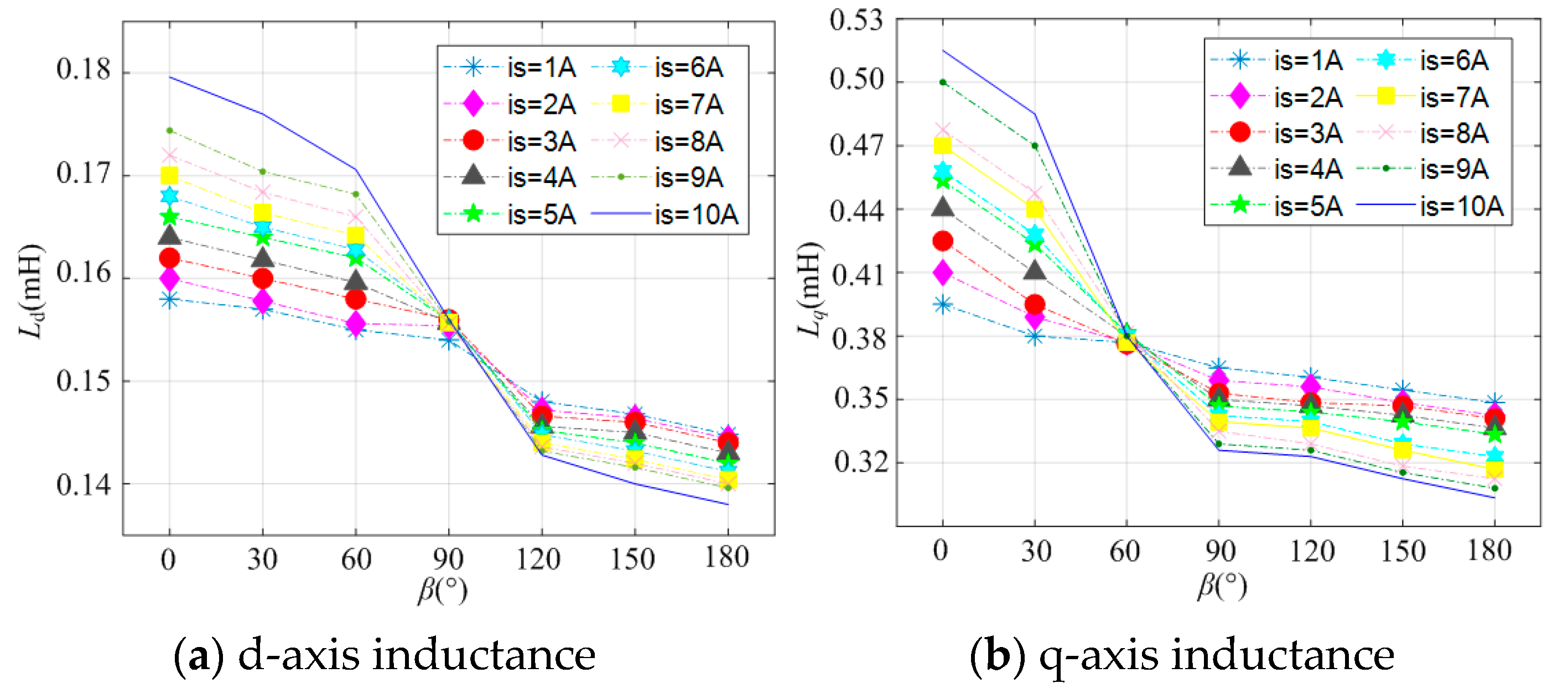
In order to obtain the dynamic change in incremental inductance under the different vector angles and currents, this paper provides the results for the d-q axes’ inductance, as shown in Figure 6, where the object is a 5 kW permanent magnet synchronous motor with four poles and a 10 A rated current. There are 70 operating points simulated by the finite element method; each sampling point comes from any two points with equal intervals between 1~10 A and 0~180°.
From Figure 6a, it can be seen that when β = 0°, that is, iq = 0, the flux produced by id completely weakens the permanent magnet flux and results in a saturation decrease in the d-axis magnetic circuit. Hence, Ld increases along with the load current. When the scope of β is in the range of 0° to 90°, the flux produced by id coexists with that produced by iq, and Ld still increases along with load current under these circumstances, which means that Ld is mainly determined by id under the rated conditions. Once the vector angle β goes beyond 90°, the current id enhances the magnetism, which causes faster saturation inside the magnetic circuit, and Ld decreases along with deeper saturation; however, the inductance does not vary much in the saturated zone. From Figure 6b, it can be observed that when β = 90°, that is, id = 0, the inductance Lq decreases as the current increases; however, unlike Ld, Lq increases firstly and then decreases within a small range of β, and the reason for this is that id weakens the magnetic field. It can be assumed that the change in Ld mainly depends on id, and the effect of iq is ignored in the actual calculation. Instead, Lq is seriously affected by cross-coupling.
The results in Figure 7 indicate that both Ld and Lq decrease as the vector angle increases. When β is located within the range of 90°, the demagnetization effect of the current causes significant inductance changes under different currents; similarly, after β goes beyond 90°, the inductance has a slight change due to magnetic saturation. Moreover, d-axis inductance is almost the same at each working point once β is located at 90°. Compared with the direct axis magnetic path, the quadrature axis magnetic path is seriously affected by cross-coupling. As shown in Figure 7b, the intersection of Lq at each working point indicates that β is located at 60°, for which the main reason is that both magnetization and demagnetization coexist, where demagnetization achieves a dominant position when β is located within the range of 60°.

3.2.1. Difference Estimation of Inductance in DQ-Axis

From (13), we have the conclusion that both Ka and Kb can be obtained directly, so long as Ld (id, iq), Lq (id, iq), and φf are identified exactly. However, the inductance varies with different load conditions, as aforementioned; moreover, cross-coupling and saturation in practical operation really make it worse.
It is noted in (13) that although both Ld (id, iq) and Lq (id, iq) are needed in the calculation process, it is sufficient to obtain the difference between the inductance in d-q axes rather than to identify the inductance value. Hence, this paper presents a simple way to calculate the difference between Ld (id, iq) and Lq (id, iq) in real-time. In general, we have the input power as follows:
P in = 1.5 ( u d i d + u q i q )
Equation (15) denotes the input power from the inverter to the motor, and the actual mechanical power is expressed as
P out = P in P loss
where Ploss denotes the whole loss, which consists of copper loss, iron loss, mechanical loss, and stray loss. In addition, the reference mechanical power is expressed as
P out = T ω
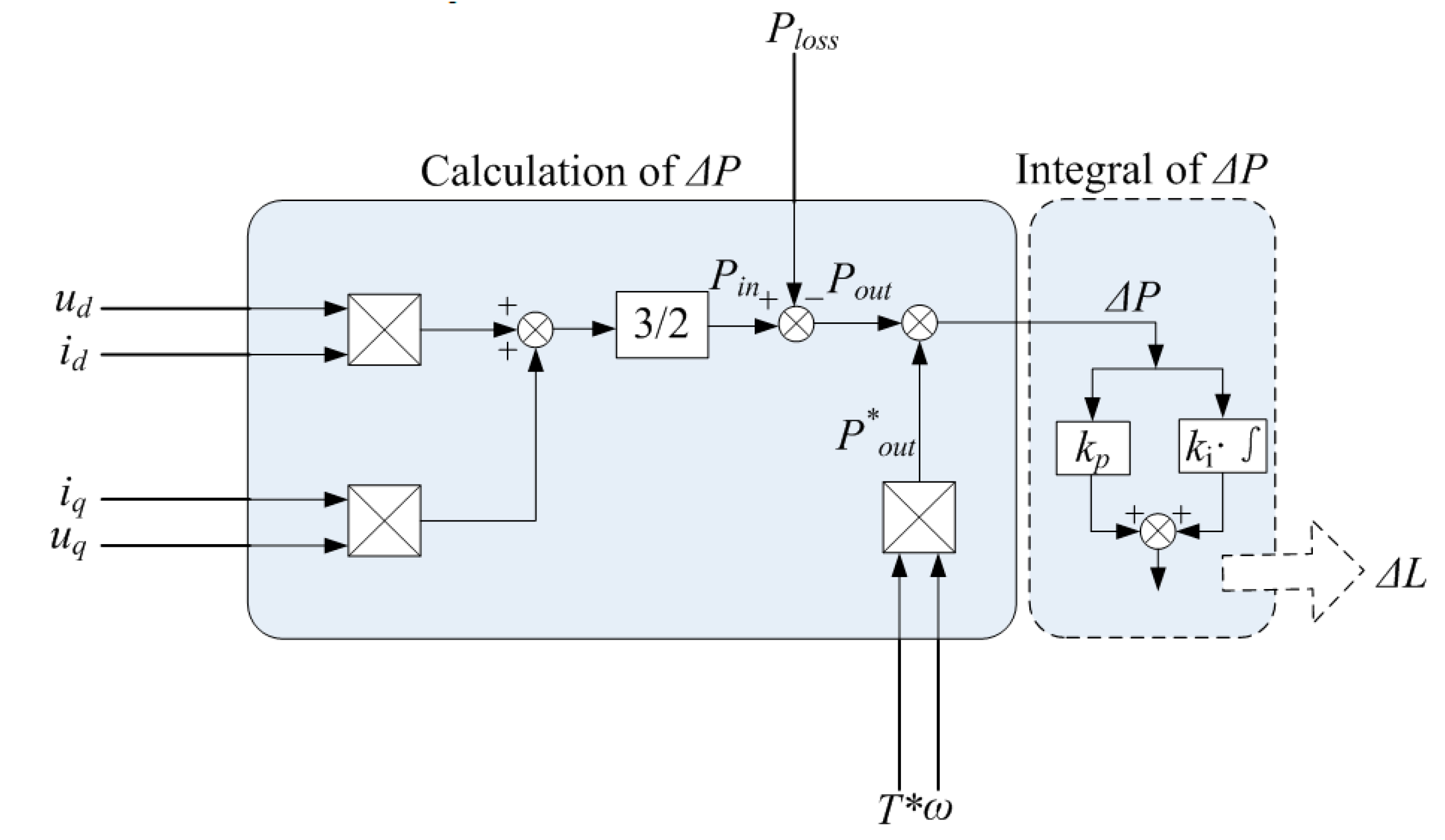
where T* is the reference torque, while ω is the speed. In practical application, the magnet flux φf is affected by the temperature and is, thus, neglected in this paper. To this end, the difference between the input power and output power mainly comes from the reluctance torque due to the inductance change, as shown in (3). Furthermore, the absolute difference between Ld (id, iq) and Lq (id, iq) makes the reluctance torque change continuously. Therefore, we attribute the power difference to the difference in inductance so that the difference in inductance in the d-q axes can be obtained according to the power, the calculation of which is designed by using the PI controller as follows:
Δ L = k p Δ P + k i Δ P
where ΔL is the absolute value of the difference between the inductance in the d-q axes, ΔP equals P*outPout, and kp, ki denote the proportional coefficient and integral coefficient, respectively. Figure 8 shows a detailed process.
Theoretically, the mechanical power Pout is equal to the reference power P*out, and the difference between them is suitable for parameter estimation. It is seen that there are seven parameters needed as input in Figure 8, where ud, uq, id, and iq are obtained from the control loop; T* is the reference signal and originates from the speed controller output; and ω is obtained from the pulse sensor. However, the loss in the motor in actual operation is unknown.

3.2.2. Estimation of Ploss

As is known, the total loss in the motor is composed of copper loss, iron loss, mechanical loss, and stray loss; to simplify the calculation process of the follow-up design, torque loss is adopted instead of power loss. Stray loss makes up a very small portion of the total loss and, thus, can be defined as a constant z1; moreover, coil resistance change is not investigated in this paper, so copper loss is considered directly related to the current in the d-q axes. Mechanical torque loss mainly refers to friction loss and can be expressed as z2ω; finally, iron loss relates to the frequency and magnetic density shown as follows:
P F e = m k ( α f B 2 + β f 2 B 2 )
where m is the quality, k is the lamination coefficient, α is the hysteresis loss coefficient, and β is the eddy current loss coefficient. B denotes magnetic density, and f is expressed as follows:
f = ω n p 2 π
By combining (19) and (20), torque loss can be obtained by eliminating ω
T F e = m k α B 2 n p 2 π + m k α B 2 n p 2 ( 2 π ) 2 ω
It can be seen from (21) that there are only two variables: magnetic density and speed. In this paper, we assume that the permanent magnet always works around the saturated range in order to make full use of material, and thus, the magnetic density B can be regarded as constant due to the slight change; therefore, (21) is rewritten as
T F e = z 3 + z 4 ω
where z3 and z4 are both constant, and the sum of these three types of torque loss is written as
T loss = z 1 + z 2 ω + z 3 + z 4 ω
Equation (23) is rewritten as
T loss = c + d ω
That is to say, we regard Tloss linear variation with respect to ω. In an actual offline test, in order to determine c and d, id = 0 control is first adopted under two different speeds with the same load, thus obtaining Tloss and T″loss; therefore, we have
T loss = c + d ω T loss = c + d ω
The solutions to the binary linear equations are c and d. Based on this analysis, a proposed approximate loss calculation process is shown in Figure 9.

4. Verification and Analysis

By combining the proposed methods above, we have a detailed control strategy based on Figure 4, as shown in Figure 10. The reference torque T* can be calculated using (3), where Ld, Lq, and φf can all be first obtained from the offline test.
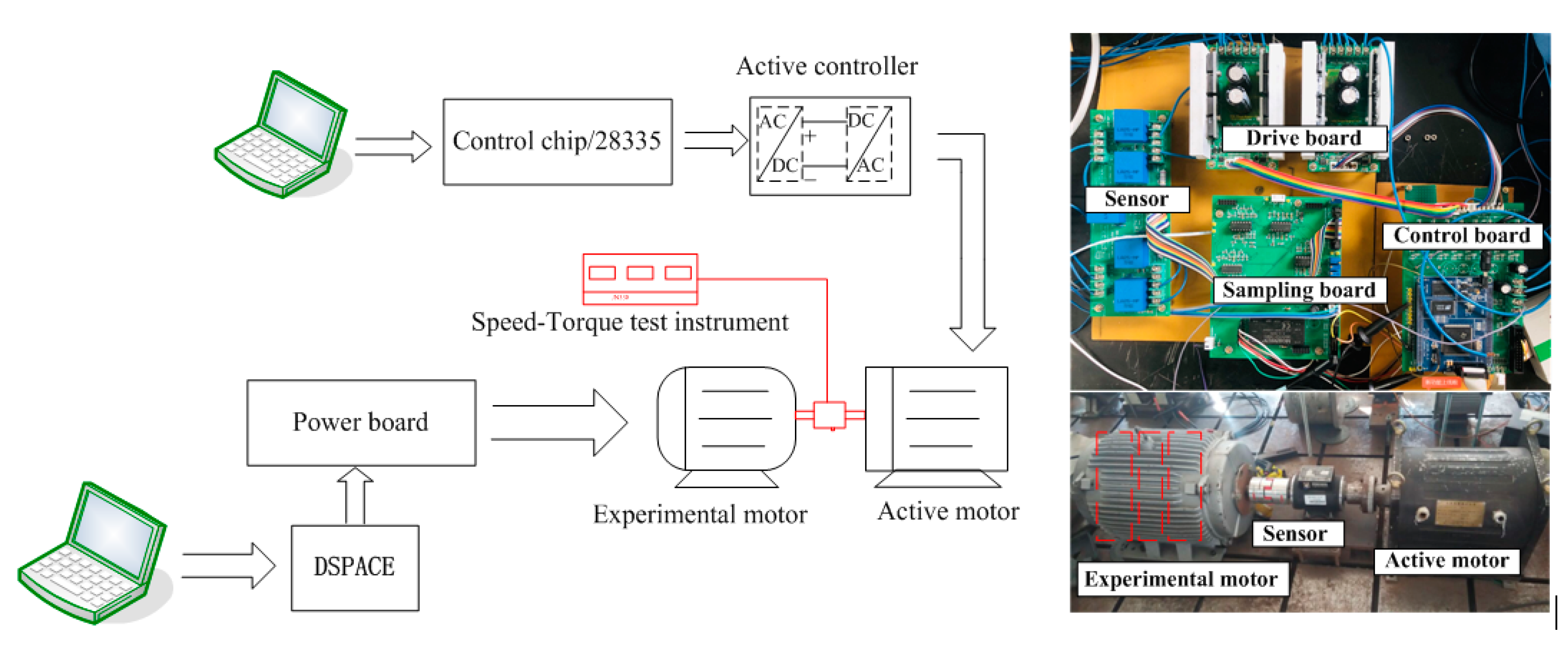
Figure 11 shows the test bench, which consists of the active motor and the experimental motor; speed control mode is adopted for the active motor and is executed by the control chip DSP28335. Moreover, the proposed algorithm is carried out by DSPACE.

4.1. Estimation of ΔL

An IPMSM is chosen as the control object, and its internal parameters are shown in Table 1.
To obtain ΔL, we have to calculate Ploss first; that is to say, the values of c and d need to be determined in advance. In actuality, it is better to divide the load into several regions, each region has different c and d values. This paper considers 500 rpm and 3000 rpm as the two speed points for convenience, with a 16 Nm load, to calculate Tloss and Tloss. From Figure 9, it can be observed that the values of c and d equal 0.16 and 0.02, respectively; thus, we have the linear iron loss calculation as follows:
P loss = 0.16 ω + 0.02 ω 2
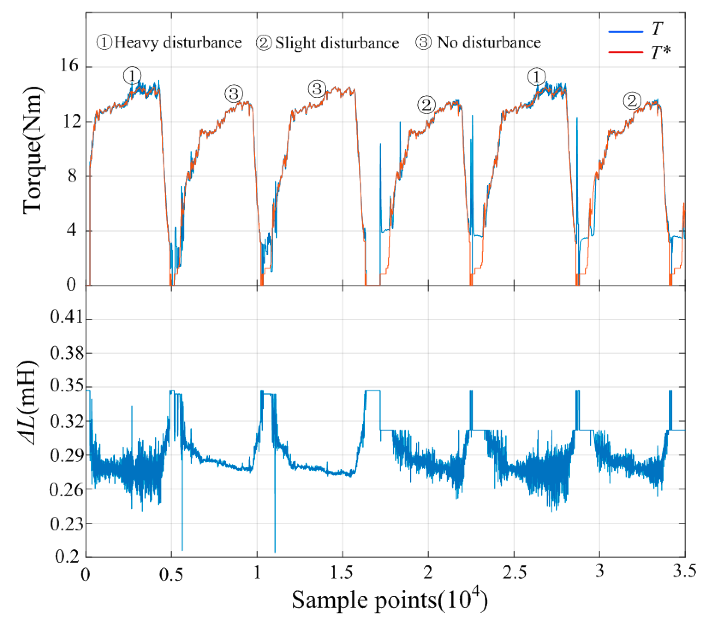
We employ (26) in the control structure, as shown in Figure 10, and then extract the data from T*, T, and ΔL, as shown in Figure 12. These three groups of data are transmitted into a computer by a serial port for display.
To obtain the dynamic performance of the proposed method, the load is designed with different random disturbances so that both the response speed and the change in ΔL can be clearly distinguished. The reference speed is given with a pattern of six start–stop cycles. From the results shown in Figure 12, it can be observed that curve ① shows dynamic changes under heavy disturbance; similarly, curve ② shows the case under slight disturbance; and curve ③ shows the case with no disturbance. It can be seen that although T* has an obvious and frequent fluctuation effect, the actual torque shows fast and accurate track performance. However, during the rise and fall process, the performance is not that accurate.
Moreover, the variation in ΔL is obvious, and its value is reduced from 0.35 to around 0.27. What is more, frequent disturbance results in obvious fluctuations in the calculation of ΔL.

4.2. Results of Control Method

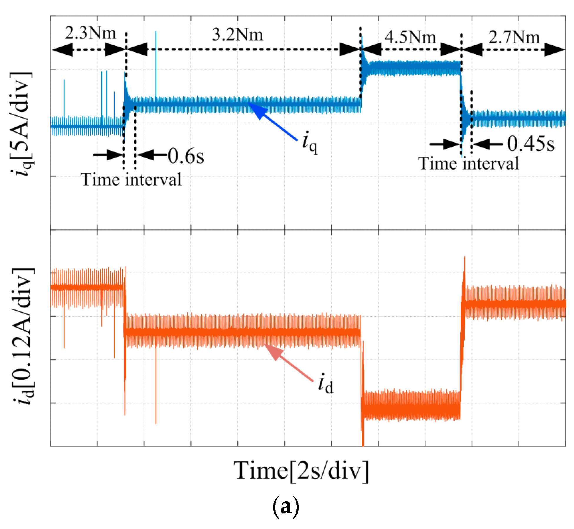
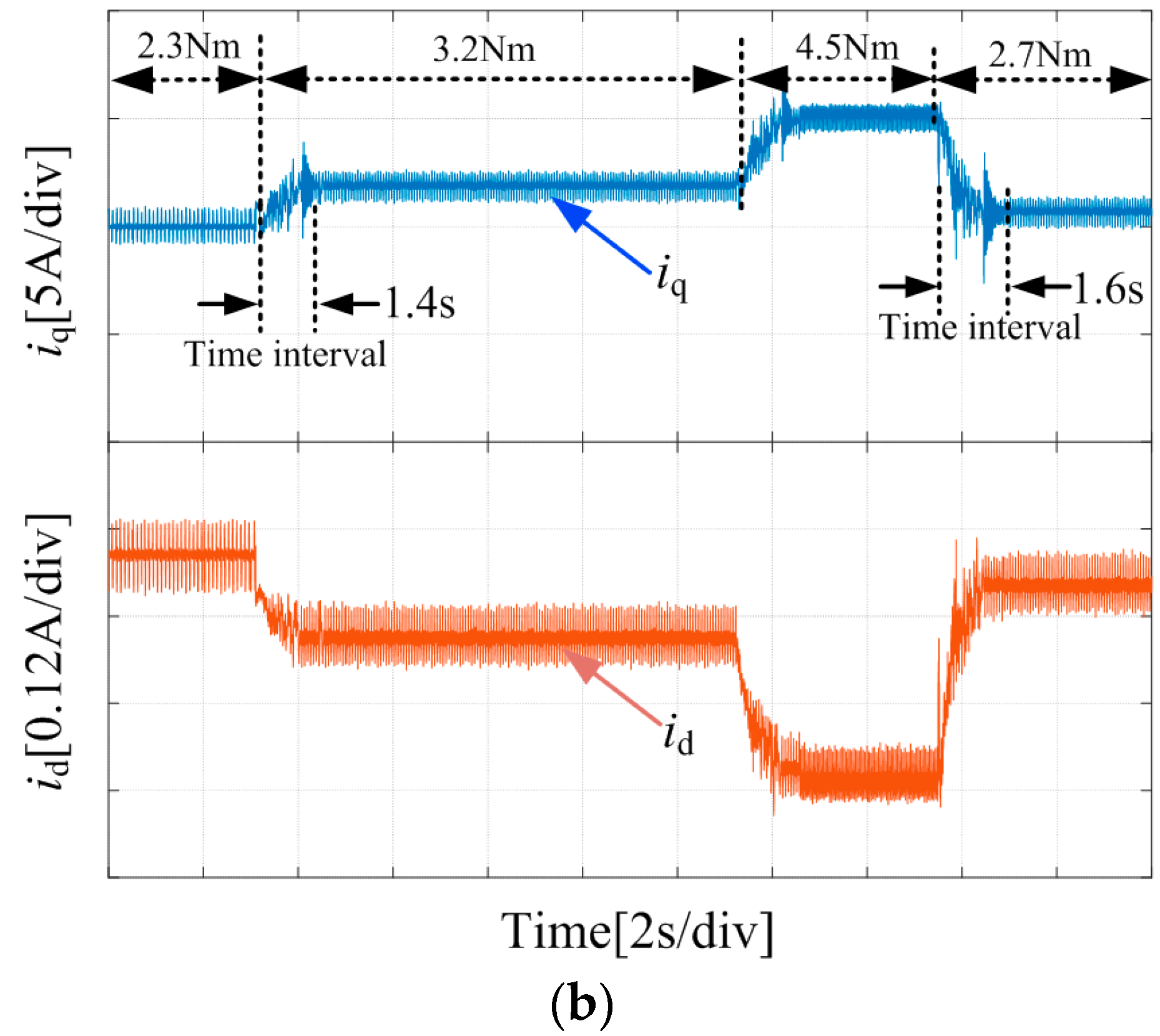
Both the proposed control scheme and the conventional MTPA method are tested. Subsequently, the d-q axes’ current dynamic curves are given in Figure 13 due to the fact that the d-q axes’ currents can reflect every transient performance in detail. The system speed is controlled at 3000 rpm by an experimental motor, and the load torque is provided by an active motor.
It can be seen from Figure 13a that when the torque suddenly changes from 2.3 Nm to 3.2 Nm, the system takes 0.3 s to reach the new stable state, where the integral gain Kp = 1000 is chosen; it should be noted that this value is not analyzed in this paper, as we have conducted many practical tests to determine it. Moreover, it takes 0.3 s to reach the stable state when the torque suddenly drops from 4.5 Nm to 2.7 Nm. For the conventional MTPA method with the observer under the same condition, the adjustment times are 0.65 s and 0.92 s, respectively. In addition, there are differences in the current results between the two methods for the same load condition, and these differences can be distinguished from the current vector angle, as shown in Table 2.
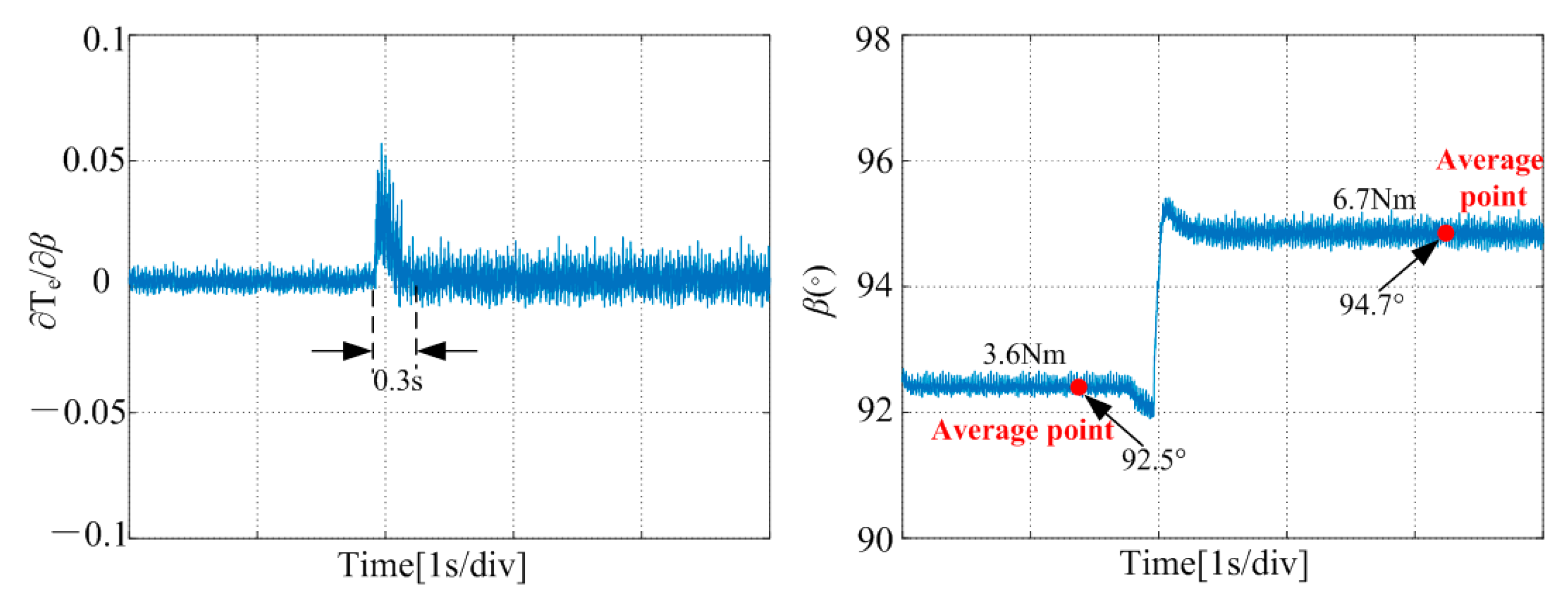
The dynamic oscillation due to the load’s sudden change can be obviously seen in Figure 14; the adjustment time for torque differentiation with respect to the current angle is 0.3 s when the load suddenly changes from 3.6 Nm to 6.7 Nm, and ∂T/∂β fluctuates around zero all the time.

5. Conclusions

The method proposed improves the current vector angle and, thus, changes the current in the d-q axes. It has three calculation stages: loss calculation, an estimation of the difference between the inductances in the d-q axes, and the integral of the angle error. The advantages of this method are described in Table 3.
However, strictly speaking, the proposed linear iron loss estimation approach is not entirely accurate due to the complexity of actual operations, and it is difficult to express loss in each stage. This is a direction for future work. Moreover, the relationship between the difference in power and the difference in inductance in the d-q axes needs to be further explored.

Author Contributions

Conceptualization, L.Z.; methodology, L.Z.; formal analysis, L.Z.; validation, L.Z., Z.C., L.S. and T.H.; investigation, L.Z., Z.C., R.Z. and W.H.; data curation, L.Z.; writing—original draft preparation, L.Z.; writing—review and editing, L.Z., Z.C. and L.S. All authors have read and agreed to the published version of the manuscript.

Funding

This research received no external funding.

Data Availability Statement

Data are contained within the article.

Conflicts of Interest

The authors Zongze Cui and Tingchen Hou are employed by Heilongjiang Dewo Technology Development Co., Ltd. The remaining authors declare that the research was conducted in the absence of any commercial or financial relationships that could be construed as potential conflicts of interest.

References

  1. Li, S.; Han, D.; Sarlioglu, B. Modeling of interior permanent magnet machine considering saturation, cross coupling, spatial harmonics, and temperature effects. IEEE Trans. Transport. Electrif. 2017, 3, 682–693. [Google Scholar] [CrossRef]
  2. Khayamy, M.; Chaoui, H. Current sensorless MTPA operation of interior pmsm drives for vehicular applications. IEEE Trans. Veh. Technol. 2018, 67, 6872–6881. [Google Scholar] [CrossRef]
  3. Han, Z.; Liu, J.; Yang, W.; Pinhal, D.B.; Reiland, N.; Gerling, D. Improved online maximum-torque-per-ampere algorithm for speed controlled interior permanent magnet synchronous machine. IEEE Trans. Ind. Electron. 2020, 67, 3398–3408. [Google Scholar] [CrossRef]
  4. Sun, J.; Lin, C.; Xing, J.; Jiang, X. Online MTPA Trajectory Tracking of IPMSM Based on a Novel Torque Control Strategy. Energies 2019, 12, 3261. [Google Scholar] [CrossRef]
  5. Ni, R.; Xu, D.; Wang, G.; Ding, L.; Zhang, G.; Qu, L. Maximum efficiency per ampere control of permanent-magnet synchronous machines, IEEE Trans. Ind. Electron. 2015, 62, 2135–2143. [Google Scholar] [CrossRef]
  6. Dianov, A.; Anuchin, A. Adaptive maximum torque per ampere control of sensorless permanent magnet motor drives. Energies 2020, 13, 5071. [Google Scholar] [CrossRef]
  7. Li, J.C. Analytical model of the cross magnetizing effect in saturated synchronous machines. Electr. Power Syst. Res. 1996, 37, 19–28. [Google Scholar] [CrossRef]
  8. Meessen, K.J.; Thelin, P.; Soulard, J.; Lomonova, A. Inductance calculation of permanent magnet synchronous machines including flux and self and cross saturation. IEEE Trans. Magn. 2008, 44, 2324–2331. [Google Scholar] [CrossRef]
  9. Li, K.; Wang, Y. Maximum torque per ampere (MTPA) control for IPMSM drives based on a variable-equivalent-parameters MTPA control law. IEEE Trans. Power Electron. 2019, 34, 7092–7102. [Google Scholar] [CrossRef]
  10. Guo, Q.; Zhang, C.; Li, L.; Zhang, J.; Wang, M. Maximum Efficiency per Torque Control of permanent-magnet Synchronous Machines. Appl. Sci. 2016, 6, 425. [Google Scholar] [CrossRef]
  11. Tang, Q.P.; Shen, A.W.; Luo, P.; Shen, H.L.; Li, W.H.; He, X.N. IPMSMs Sensorless MTPA Control Based on Virtual q-Axis Inductance by Using Virtual High-Frequency Signal Injection. IEEE Trans. Ind. Electron. 2020, 67, 136–146. [Google Scholar] [CrossRef]
  12. Sun, T.F.; Koc, M.; Wang, J. MTPA control of IPMSM drives based on virtual signal injection considering machine parameters variations. IEEE Trans. Ind. Electron. 2018, 65, 6089–6098. [Google Scholar] [CrossRef]
  13. Liu, Q.; Hameyer, K. High-Performance adaptive torque control for an IPMSM with real-time MTPA Operation. IEEE Trans. Energy Conv. 2017, 32, 571–581. [Google Scholar] [CrossRef]
  14. Consoli, A.; Scarcella, G.; Scelba, G.; Testa, A. Steady-state and transient operation of IPMSMs under maximum-torque-per-ampere control. IEEE Trans. Ind. Appl. 2010, 46, 121–129. [Google Scholar] [CrossRef]
  15. Mohamed, Y.A.-R.I.; Lee, T.K. Adaptive self-tuning MTPA vector controller for IPMSMdrive system. IEEE Trans. Energy Conv. 2006, 21, 636–644. [Google Scholar] [CrossRef]
  16. Hajime, H.; Yoshio, T.; Keiji, K. Novel sensorless control for pmsynchronous motors based on maximum torque control frame. In Proceedings of the 2007 European Conference on Power Electronics and Applications, Aalborg, Denmark, 2–5 September 2007; pp. 1–10. [Google Scholar]
  17. Inoue, T.; Inoue, Y.; Morimoto, S.; Sanada, M. Maximum torque per ampere control of a direct torque-controlled PMSM in a stator flux linkage synchronous frame. IEEE Trans. Ind. Appl. 2016, 52, 2360–2367. [Google Scholar] [CrossRef]
  18. Zhang, Y.; Yin, Z.; Bai, C.; Wang, G.; Liu, J. A rotor position and speed estimation method using an improved linear extended state observer for IPMSM sensorless drives. IEEE Trans. Power Electron. 2021, 36, 14062–14073. [Google Scholar] [CrossRef]
  19. Lin, F.J.; Chen, S.G.; Liu, Y.T.; Chen, S.Y. A power perturbation-based MTPA control with disturbance torque observer for IPMSM drive system. Trans. Inst. Meas. Control 2018, 40, 3179–3288. [Google Scholar] [CrossRef]
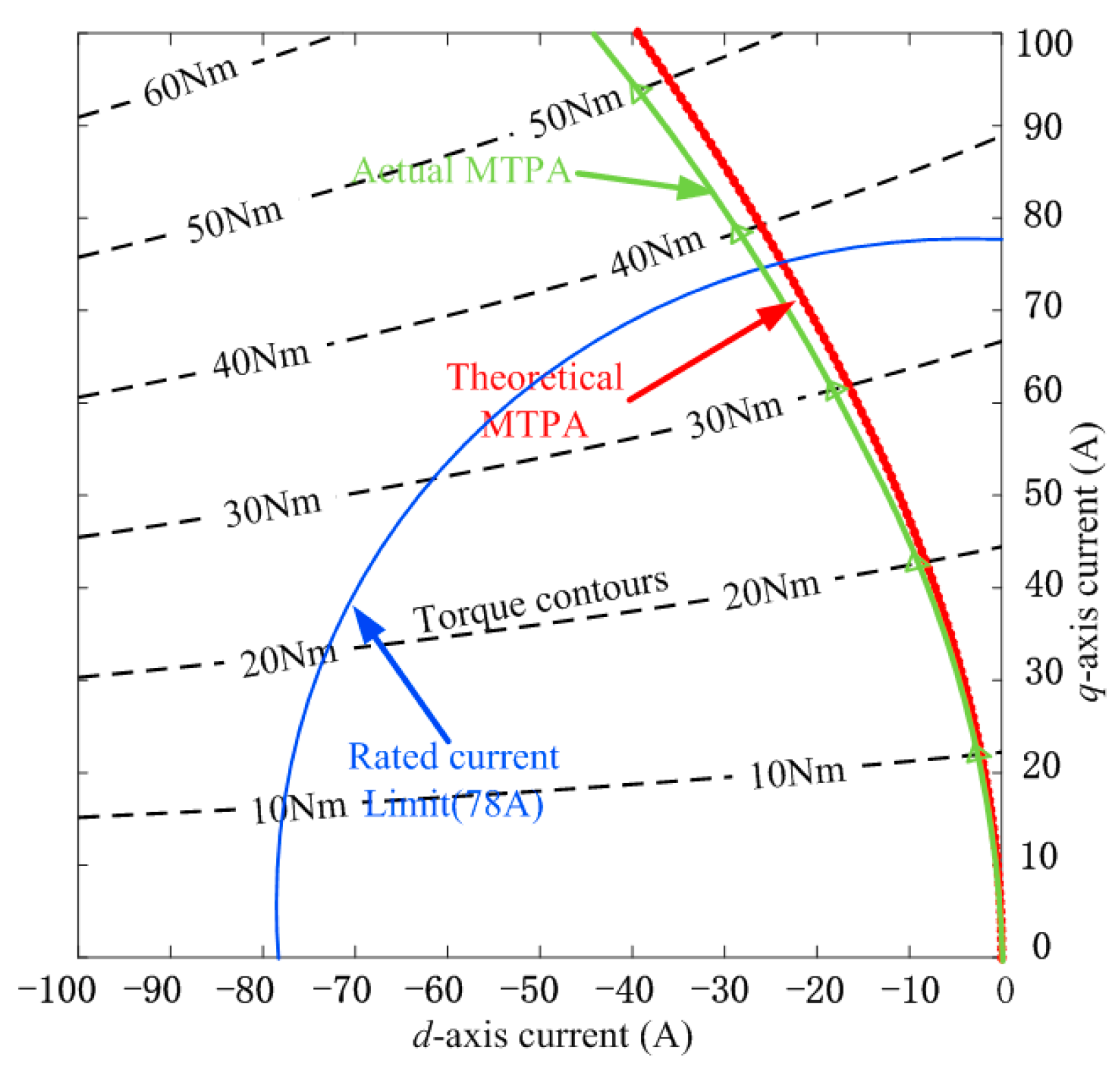
Figure 1. MTPA loci and torque contours.
Energies 17 04905 g001
Figure 2. Relationship between torque and current vector angle.
Energies 17 04905 g002
Figure 3. Error-driven closed-loop structure.
Energies 17 04905 g003
Figure 4. Structure of current vector angle compensation in d-axis. * represents the reference value.
Energies 17 04905 g004
Figure 5. Relationship of current vector in d-q coordinate.
Energies 17 04905 g005
Figure 6. The inductance in d-q axes.
Energies 17 04905 g006
Figure 7. Effect on inductance with different vector angles under different currents.
Energies 17 04905 g007
Figure 8. Detailed calculation of ΔL.
Energies 17 04905 g008
Figure 9. Detailed calculation of Ploss.
Energies 17 04905 g009
Figure 10. Changes in MTPA curve due to variable Lq.
Energies 17 04905 g010
Figure 11. Structure of test bench.
Energies 17 04905 g011
Figure 12. Dynamic speed and ΔL curves.
Energies 17 04905 g012
Figure 13. Dynamic performance at 3000 rpm. (a) Current vector angle compensation method. (b) Conventional method.
Energies 17 04905 g013aEnergies 17 04905 g013b
Figure 14. Current vector angle curves under the sudden change.
Energies 17 04905 g014
Table 1. Parameters of IPMSM.
SymbolExplanationValue and Unit
pNumber of pole pairs4
LdD-axis inductance0.18 mH
LqQ-axis inductance0.53 mH
RResistance10.2 mΩ
nNRated speed3000 rpm
PNRated power5 kW
TNRated torque16 Nm
Table 2. Parameters related to the method.
TorqueProposed MethodConventional Method
2.3 Nm91.91°91.6°
3.2 Nm92.36°92.05°
4.5 Nm92.92°92.63°
2.7 Nm92.08°91.65°
Table 3. The advantages analysis.
Comparison ItemDescription
Response speedThe proposed method has a faster response, although with a transient impact when the load changes.
AccuracyMore accurate results can be obtained from the method proposed, though they are not optimal.
ImplementationThe algorithm is indeed simple, less calculation, and low complexity.
Disclaimer/Publisher’s Note: The statements, opinions and data contained in all publications are solely those of the individual author(s) and contributor(s) and not of MDPI and/or the editor(s). MDPI and/or the editor(s) disclaim responsibility for any injury to people or property resulting from any ideas, methods, instructions or products referred to in the content.